

Page 1

AXN 1 10
Pseudo-Wire Access Device
U ser Gu ide
®
Unloc k the Powe r of Your IP N e twor k
Ver 2.9.82
Page 2

This document is subject to the following conditions and restrictions:
This document contains proprietary information belonging to Axerra Networks Inc. Such
information is supplied solely for the purpose of assisting explicitly authorized users of the
Axerra Pseudo-Wire product line.
Axerra Networks owns the proprietary rights to all information contained herein. No part of this
publication may be reproduced, stored in a retrieval system, nor transmitted in any form or by
any means, electronic, mechanical, magnetic, photocopy, recording, or otherwise, now or in the
future, without prior written consent from Axerra Networks.
The text and graphics are for illustration and reference only. The specifications on which they
are based are subject to change without notice.
Due to a policy of continuous development, Axerra Networks reserves the right to alter
specifications and descriptions outlined in this publication without prior notice, and no prt of
this publication, taken separately or as a whole, shall be deemed to be part of any contract for
the equipment.
Copyright © 20 CFM04, 2005, 2006, 2007, 2008, 2009, 2010 Axerra Networks Inc.
Axerra Networks
Your IP Network
®
, Axerra®, The Pseudo-Wire Company®, AXN®, HPCR®, Unlock the Power of
®
and Multiservice Packet Concentrator™ are trademarks or registered
trademarks of Axerra Networks Inc. All other product names are trademarks or registered
trademarks of their respective owners and are hereby acknowledged.
Document Number:
AccessDevice AXN 1 10UGV2.9.82
Page 3

Table of Contents
Chapter 1: Introduction ....................................................................... 1-1
1.1 General Description ....................................................................................................... 1-1
1.2 Supported Services and Features ................................................................................. 1-2
1.3 Key Applications ............................................................................................................ 1-2
1.4 Key Features ................................................................................................................. 1-3
1.5 Timing Options .............................................................................................................. 1-3
1.6 Management Options .................................................................................................... 1-4
1.6.1 Inband Management for an Ethernet Uplink.......................................................... 1-5
1.6.2 Out Of Band Management for an Ethernet Port ................................................... 1-5
1.7 Ordering Options ........................................................................................................... 1-6
1.7.1 Accessories .......................................................................................................... 1-7
1.8 Physical Description ...................................................................................................... 1-8
1.8.1 AXN1 Family ........................................................................................................ 1-8
1.8.2 Technical Specifications for AXN1 Family .......................................................... 1-10
1.8.3 Power Supply Module (PSM) for AXN1 Family ................................................... 1-11
1.8.4 AXN10 Family .................................................................................................... 1-12
1.8.5 Technical Specifications for AXN10 Family......................................................... 1-13
1.8.6 Power Supply Module (PSM) for AXN10 Family ................................................. 1-15
1.8.7 AXN10G Family .................................................................................................. 1-15
1.8.8 Technical Specifications for AXN10G Family ...................................................... 1-17
1.8.9 Power Supply Module (PSM) for AXN10G Family .............................................. 1-18
Chapter 2: Installation ......................................................................... 2-1
2.1 Safety Guidelines .......................................................................................................... 2-1
2.2 Unpacking the AXN1/10 ................................................................................................ 2-1
2.3 Installation Requirements .............................................................................................. 2-2
3.1 Safety During AXN1/10 Installation ....................................................................... 2-2
2.
2.3.2 Environmental Requirements ............................................................................... 2-2
2.3.3 Clearance Requirements ...................................................................................... 2-3
2.3.4 System Grounding Requirements ......................................................................... 2-3
2.3.5 Power Requirements ............................................................................................ 2-4
2.3.6 Power Supply Safety ............................................................................................ 2-4
2.3.7 Cord Safety .......................................................................................................... 2-4
2.4 Site Preparation Checklist ............................................................................................. 2-5
2.5 Installation Procedure .................................................................................................... 2-5
2.5.1 Tools Required for Rack Mounting ....................................................................... 2-5
2.5.2 Mounting the AXN1/10 ......................................................................................... 2-5
2.6 Power Supply .............................................................................................................. 2-10
2.7 Pinouts ........................................................................................................................ 2-12
2.7.1 Ethernet Port Pinouts (UTP) ............................................................................... 2-13
2.7.2 T1/E1 Port Pinouts ............................................................................................. 2-13
2.7.3 Serial (V.35) Port Pinouts ................................................................................... 2-13
Chapter 3: Initial Configurati on .......................................................... 3-1
3.1 Connecting the AXN1/10 to a Local Terminal ................................................................ 3-1
3.2 Logging In ...................................................................................................................... 3-2
3.3 Increasing Your Privilege Level ..................................................................................... 3-3
3.4 Clearing the Current Database ...................................................................................... 3-3
3.5 Setting the Board Type .................................................................................................. 3-4
AccessDevice AXN 1 10UGV2.9.82 i
Page 4

Table of Contents
3.6 Changing Your Password .............................................................................................. 3-4
3.7 Setting the AXN1/10's IP Address ................................................................................. 3-5
3.8 Enabling Management IP Access .................................................................................. 3-6
3.8.1 Configuring Management Access ......................................................................... 3-6
3.9 Route Delete ................................................................................................................. 3-8
3.9.1 Configuring VLAN ID ............................................................................................ 3-8
3.10 Enabling the Ethernet Port ............................................................................................. 3-8
3.11 Defining a New System Name ....................................................................................... 3-9
3.12 Saving Your Changes .................................................................................................... 3-9
3.13 Ending the Session ........................................................................................................ 3-9
3.14 Connecting the Ethernet Cable .................................................................................... 3-10
Chapter 4: Command Line Interface ................................................... 4-1
4.1 AXN1/10 Management Options ..................................................................................... 4-1
4.1.1 Telnet Management .............................................................................................. 4-2
4.1.2 SSH Management ................................................................................................ 4-2
4.1.3 SNMP Management ............................................................................................. 4-2
4.1.4 Using the Local Terminal to Access other AXNs via Telnet .................................. 4-4
4.1.5 Using the Local Terminal to Access other AXNs via SSH ..................................... 4-4
4.1.6 Simultaneous Management Sessions ................................................................... 4-4
4.2 Using the CLI ................................................................................................................. 4-5
4.2.1 Understanding the Basic Command Line Format ................................................. 4-5
4.2.2 General CLI Syntax Rules .................................................................................... 4-6
4.2.3 Command Line Modes ......................................................................................... 4-6
4.2.4 General Tips ......................................................................................................... 4-7
4.2.5 Using the Autocomplete Function ......................................................................... 4-7
4.
2.6 Using the Command History ................................................................................. 4-8
4.2.7 Viewing Detailed Information ................................................................................ 4-8
4.2.8 Listing Information ................................................................................................ 4-9
4.2.9 Using Aliases ........................................................................................................ 4-9
4.3 Using CLI Online Help ................................................................................................... 4-9
4.3.1 Requesting Help Information ................................................................................ 4-9
4.3.2 Correcting Syntax Errors .................................................................................... 4-10
4.3.3 Interpreting Error Messages ............................................................................... 4-11
4.4 CLI Command Reference ............................................................................................ 4-11
4.4.1 CLI Command Set .............................................................................................. 4-11
4.4.2 Terminal Control Commands and Keyboard Shortcuts ....................................... 4-14
4.5 SNTP Support ............................................................................................................. 4-16
4.5.1 Configuring the SNTP Server ............................................................................. 4-17
Chapter 5: Security .............................................................................. 5-1
5.1 Defining Users and User Privilege Levels ...................................................................... 5-1
5.1.1 Adding a User ....................................................................................................... 5-1
5.1.2 Deleting a User ..................................................................................................... 5-2
5.1.3 Viewing the User List ............................................................................................ 5-2
5.1.4 Changing a User's Password ................................................................................ 5-2
5.2 Using a RADIUS Server for Authentication .................................................................... 5-2
5.2.1 Configuring the RADIUS Server ........................................................................... 5-2
5.2.2 Adding a RADIUS Server ..................................................................................... 5-3
5.2.3 Deleting a RADIUS Server ................................................................................... 5-3
5.2.4 Viewing the List of RADIUS Servers ..................................................................... 5-3
5.3 Managing the IP Access Control List ............................................................................. 5-3
3.1 Adding an IP to the IP Access List ........................................................................ 5-4
5.
ii AccessDevice AXN 1 10UGV2.9.82
Page 5

Table of Contents
5.3.2 Deleting the IP Access List ................................................................................... 5-5
5.3.3 Viewing the IP Access List .................................................................................... 5-5
5.4 Managing the SSH Server ............................................................................................. 5-6
5.4.1 Enabling SSH Access ........................................................................................... 5-6
5.4.2 Starting the SSH Server ....................................................................................... 5-6
5.4.3 Stopping the SSH Server...................................................................................... 5-6
5.4.4 Viewing the SSH Server Info ................................................................................ 5-7
5.4.5 Setting the SSH Server Timeout ........................................................................... 5-7
5.4.6 Setting the SSH Server Login Retry ..................................................................... 5-8
Chapter 6: Software Download and Mana ge m e nt ............................. 6-1
6.1 Exporting and Restoring the Database .......................................................................... 6-1
6.1.1 Exporting the Database ........................................................................................ 6-1
6.1.2 Restoring the Database ........................................................................................ 6-2
6.2 Local Restore Management ........................................................................................... 6-3
6.2.1 Purpose ................................................................................................................ 6-3
6.2.2 Command Syntax ................................................................................................. 6-3
6.3 Downloading a New Software Version ........................................................................... 6-5
6.4 Activating a Software Version ........................................................................................ 6-6
6.5 Deleting a Software Version .......................................................................................... 6-7
6.6 Displaying the Software Version List .............................................................................. 6-7
6.7 Reverting to Factory Settings ......................................................................................... 6-7
6.7.1 Returning to Regular Initialization Procedure ........................................................ 6-8
6.7.2 Reset to Factory Settings ..................................................................................... 6-9
6.7.3 Reset to Restore Point ......................................................................................... 6-9
Chapter 7: General Configurati on....................................................... 7-1
7.1 System Management ..................................................................................................... 7-1
7.
1.1 Configuring System Attributes .............................................................................. 7-1
7.1.2 Configuring Inband Management for T1/E1 Uplinks.............................................. 7-3
7.1.3 Viewing System Alarms ........................................................................................ 7-4
7.1.4 Viewing System Information ................................................................................. 7-5
7.2 Multiple IP Subnets ........................................................................................................ 7-6
7.2.1 Creating IPoETH .................................................................................................. 7-7
7.2.2 Configuring Static Routes ..................................................................................... 7-8
7.2.3 Creating a VLAN Connection ................................................................................ 7-9
7.2.4 Using BFD .......................................................................................................... 7-11
7.3 System C l ock .............................................................................................................. 7-17
7.3.1 Configuring the System Clock............................................................................. 7-17
7.3.2 Viewing System Clock Information ..................................................................... 7-18
7.4 Out of Band (OOB) HPCR Source: SYNCH-PW Service ............................................. 7-18
7.4.1 Sync-PW Parameters ......................................................................................... 7-20
7.4.2 Modifying the Sync-PW Service .......................................................................... 7-20
7.4.3 Sync-PW Statistics ............................................................................................. 7-21
7.4.4 Sync-PW Alarms ................................................................................................ 7-21
7.5 Displaying the List of All Ports, Tunnels, and Services................................................. 7-21
7.6 Physical Ports .............................................................................................................. 7-23
7.6.1 Configuring a Physical Port ................................................................................ 7-23
7.6.2 Viewing Port Information..................................................................................... 7-26
7.6.3 Physical Port Alarms .......................................................................................... 7-29
7.6.4 Displaying a List of Ports .................................................................................... 7-30
7.7 Frame Relay Ports ....................................................................................................... 7-31
7.7.1 FR
F (Frame Relay Fragmented) Port ................................................................. 7-31
AccessDevice AXN 1 10UGV2.9.82 iii
Page 6

Table of Contents
7.7.2 Single Command Line Method for Creating an FRF12 Frame Relay Port ........... 7-31
7.7.3 Interactive Mode Method for Creating an Frf12 Port ........................................... 7-32
7.8 Deleting a Frame Relay Port ........................................................................................ 7-33
7.8.1 Configuring a Frame Relay Port ......................................................................... 7-33
7.8.2 Viewing Frame Relay Port Information ............................................................... 7-34
7.8.3 Displaying the List of Frame Relay Ports ............................................................ 7-35
7.8.4 Deleting a Frame Relay Port .............................................................................. 7-35
7.9 ATM Ports ................................................................................................................... 7-36
7.9.1 Creating an ATM Port ......................................................................................... 7-37
7.9.2 Configuring an ATM Port .................................................................................... 7-37
7.9.3 Viewing ATM Port Information ............................................................................ 7-38
7.9.4 Displaying the List of ATM Ports ......................................................................... 7-38
7.9.5 ATM Port Alarms ................................................................................................ 7-39
7.9.6 Deleting an ATM Port ......................................................................................... 7-39
7.10 IMA Grouping .............................................................................................................. 7-39
7.10.1 How IMA Works .................................................................................................. 7-40
7.10.2 IMA in Axerra Applications .................................................................................. 7-41
7.10.3 Overview of IMA Group Configuration ................................................................ 7-41
7.10.4 Creating an IMA Link on a T1/E1 interface ......................................................... 7-42
7.10.5 Viewing an IMA Link ........................................................................................... 7-42
7.10.6 Creating an IMA Group Using the Command Line .............................................. 7-44
7.10.7 Creating an IMA Goup Interactively .................................................................... 7-44
7.10.8 Viewing an IMA Group ........................................................................................ 7-45
7.10.9 Parameters for an IMA Group ............................................................................. 7-46
7.10.10 Creating an ATM Service .................................................................................... 7-50
7.10.11 Deleting an IMA Service ..................................................................................... 7-50
7.
10.12 IMA Link Alarms and Status ............................................................................... 7-50
7.10.13 Vie wing IMA Link Alarms .................................................................................... 7-51
7.10.14 IMA Group Alarms .............................................................................................. 7-51
7.10.15 IMA Group Status Propagation ........................................................................... 7-52
7.10.16 IMA Link Statistics .............................................................................................. 7-53
7.11 Using VCCV BFD ........................................................................................................ 7-53
7.11.1 Creating a VCCV BFD ........................................................................................ 7-54
7.11.2 Configuring a VCCV BFD ................................................................................... 7-55
7.11.3 Viewing VCCV BFD Informat ion ......................................................................... 7-56
7.11.4 Deleting VCCV BFD session .............................................................................. 7-58
7.12 ARP Table ................................................................................................................... 7-58
7.12.1 Viewing the ARP Table ....................................................................................... 7-58
7.12.2 Adding Entries to the ARP Table ........................................................................ 7-59
7.12.3 Removing Entries from the ARP Table ............................................................... 7-59
Chapter 8: Service Configuration ....................................................... 8-1
8.1 Pseudo-Wire Services ................................................................................................... 8-1
8.1.1 Summary of Steps for Creating a Pseudo-Wire Service ....................................... 8-2
8.1.2 Using Tunnels ...................................................................................................... 8-4
8.1.3 Using SIG Descriptors ........................................................................................ 8-11
8.1.4 Creating a Pseudo-Wire Service ......................................................................... 8-17
8.1.5 Configuring a Pseudo-Wire Service .................................................................... 8-17
8.1.6 Displaying a List of Pseudo-Wire Services ......................................................... 8-17
8.1.7 Deleting a Pseudo-Wire Service ......................................................................... 8-18
8.2 IP Service Interworking ................................................................................................ 8-18
8.2.1 S
8.2.2 Creating a Frame Relay IP Interworking Service ................................................ 8-20
8.2.3 Modifying a Frame Relay IP Interworking Service.............................................. 8-20
8.2.4 Viewing Frame Relay IP Interworking Service Information .................................. 8-21
iv AccessDevice AXN 1 10UGV2.9.82
ummary of Steps for Creating an IP Interworking Service ................................ 8-19
Page 7

Table of Contents
8.2.5 Creating an HDLC IP Interworking Service ......................................................... 8-22
8.2.6 Modifying an HDLC IP Interworking Service ....................................................... 8-23
8.2.7 Viewing HDLC IP Interworking Service Information ............................................ 8-24
8.2.8 Creating a PPP IP Interworking Service ............................................................. 8-25
8.2.9 Modifying a PPP IP Interworking Service ............................................................ 8-26
8.2.10 Viewing PPP IP I nterworking Service Informat i on ............................................... 8-27
8.2.11 Displaying a List of IP Interworking Services ...................................................... 8-28
8.2.12 Deleting an IP Interworking Service .................................................................... 8-28
8.3 Ethernet Forwarding .................................................................................................... 8-28
8.3.1 Forwarding Traffic between the LAN and Ethernet Uplink Interface .................... 8-29
8.3.2 Forwarding Traffic between the LAN and T1/E1 Interface ................................... 8-31
Chapter 9: Bandwidth Management ................................................... 9-1
9.1 Bit Rate Policing ............................................................................................................ 9-1
9.1.1 Creating a Bit Rate Policer ................................................................................... 9-2
9.1.2 Associating a Bit Rate Policer with a Service ........................................................ 9-3
9.1.3 Assigning an Alias to a Bit Rate Policer ................................................................ 9-3
9.1.4 Viewing a Bit Rate Policer .................................................................................... 9-4
9.1.5 Displaying the List of Bit Rate Po lic ers ................................................................. 9-4
9.1.6 Deleting a Bit Rate Policer .................................................................................... 9-5
9.2 Ethernet Rate Policing (Rate Limiting) ........................................................................... 9-5
9.2.1 Creating an Ethernet Policer ................................................................................. 9-5
9.2.2 Associating an Ethernet Policer with a Port .......................................................... 9-6
9.2.3 Assigning an Alias to an Ethernet Policer ............................................................. 9-6
9.2.4 Viewing an Ethernet Policer .................................................................................. 9-6
9.2.5 Displaying the List of Ethernet Policers ................................................................. 9-7
9.2.6 Deleting an Ethernet Policer ................................................................................. 9-7
Chapter 10: CES Pseudo-Wire.......................................................... 10-1
10.1 Creating a CES Pseudo-Wire Service ......................................................................... 10-1
10.1.1 Single Command Line Method for Creating a CES Pseudo-Wire Service ........... 10-1
10.1.2 Interactive Mode Method .................................................................................... 10-4
10.1.3 Configuring CES Pseudo-Wire Services between Two AXNs ............................. 10-4
10.1.4 Creating a T1/E1 CES Bundling Service ............................................................. 10-5
10.1.5 CES Pseudo-Wire Service with CAS Sign alin g ................................................... 10-6
10.2 Modifying a CES Pseudo-Wire Service ........................................................................ 10-7
10.2.1 ConfigJitter ....................................................................................................... 10-10
10.2.2 SupportingTunnel ............................................................................................. 10-10
10.2.3 DiffServClass .................................................................................................... 10-11
10.2.4 AutoAdjustDelay ............................................................................................... 10-11
10.2.5 PacketLossRaiseDelay ..................................................................................... 10-12
10.2.6 RemoteCmdResponse ..................................................................................... 10-12
10.2.7 resyncMode ...................................................................................................... 10-13
10.3 Deleting a CES Pseudo-Wire Service ........................................................................ 10-13
10.4 Statistics .................................................................................................................... 10-14
10.5 Alarms ....................................................................................................................... 10-14
Chapter 11: Frame Relay Pseudo-Wire ............................................ 11-1
11.1 Creating a Frame Relay Pseudo-Wire Service ............................................................ 11-1
11.1.1 Single Command Line Method for Creating a FR Pseudo-Wire Service ............. 11-1
11.1.2 Interactive Mode Method for Creating a FR Pseudo-Wire Service ...................... 11-3
11.2 Configuring Frame Relay Pseudo-Wire Services between Two AXNs ......................... 11-3
11.3 Modifying a Frame Relay Pseudo-Wire Service ........................................................... 11-4
11.
3.1 CMoIP ................................................................................................................ 11-7
AccessDevice AXN 1 10UGV2.9.82 v
Page 8

Table of Contents
11.3.2 SupportingTunnel ............................................................................................... 11-7
11.3.3 DiffServClass ...................................................................................................... 11-8
11.4 Deleting a Frame Relay Pseudo-Wire Service ............................................................. 11-8
11.5 Statistics ...................................................................................................................... 11-8
11.6 Alarms ......................................................................................................................... 11-9
11.7 Frame Relay Policing................................................................................................. 11-10
11.7.1 Overview .......................................................................................................... 11-10
11.7.2 Creating a Bit Rate Policer Descriptor .............................................................. 11-11
11.7.3 Modifying a Bit Rate Policer De s crip tor ............................................................. 11-13
11.7.4 Deleting a Bit Rate Policer Des cr ip tor ............................................................... 11-14
11.7.5 Associating a FR Pseudo-Wire Service with a Bit Rate Policer Descriptor ........ 11-14
Chapter 12: HDLC Pseudo-Wire ....................................................... 12-1
12.1 Creating an HDLC Pseudo-Wire Service ..................................................................... 12-1
12.1.1 Single Command Line Method for Creating an HDLC Pseudo-Wire Service....... 12-1
12.1.2 Interactive Mode Method for Creating an HDLC Pseudo-Wire Service ............... 12-3
12.1.3 Configuring HDLC Pseudo-Wire Services between Two AXNs ........................... 12-3
12.2 Modifying an HDLC Pseudo-Wire Service ................................................................... 12-4
12.2.1 CMoIP ................................................................................................................ 12-6
12.2.2 SupportingTunnel ............................................................................................... 12-7
12.2.3 DiffServClass ...................................................................................................... 12-7
12.3 Deleting an HDLC Pseudo-Wire Service...................................................................... 12-7
12.4 Statistics ...................................................................................................................... 12-7
12.5 Alarms ......................................................................................................................... 12-8
12.6 Bit Rate Policing .......................................................................................................... 12-9
12.7 HDLC Bundling .......................................................................................................... 12-10
12.
7.1 HDLC B un d le T ransm ission ............................................................................. 12-11
12.7.2 Overview of Operations for Creating an HDLC Bundle ..................................... 12-11
12.8 Creating an HDLC Bundle ......................................................................................... 12-11
12.9 Modifying an HDLC Bundle Configuration .................................................................. 12-12
12.10 Statistics .................................................................................................................... 12-14
12.11 Alarms ....................................................................................................................... 12-14
12.12 Deleting an HDLC Bundle .......................................................................................... 12-15
Chapter 13: ATM Pseudo-Wire ......................................................... 13-1
13.1 ATM Frame (AAL5) Pseudo-Wire Services .................................................................. 13-1
13.1.1 Creating an ATM Frame (AAL5) Pseudo-Wire Service ....................................... 13-2
13.1.2 Configuring ATM Frame (AAL5) Pseudo-Wire Services between Two AXNs...... 13-4
13.1.3 Modifying an ATM Frame (AAL5) Pseudo-Wire Service ..................................... 13-5
13.1.4 Deleting an ATM Frame (AAL5) Pseudo-Wire Se rvice ....................................... 13-6
13.1.5 Statistics ............................................................................................................. 13-7
13.1.6 Alarms ................................................................................................................ 13-7
13.2 ATM Cell (AAL0) Pseudo-Wire Services ...................................................................... 13-8
13.2.1 Creating an ATM Cell (AAL0) Pseudo-Wire Service ........................................... 13-8
13.2.2 Configuring ATM Cell (AAL0) Pseudo-Wire Services between Two AXNs ........ 13-10
13.2.3 Modifying an ATM Cell (AAL0) Pseudo-Wire Ser v ice ....................................... 13-11
13.2.4 Deleting an ATM Cell (AAL0) Pseudo-Wire Service .......................................... 13-13
13.2.5 Statistics ........................................................................................................... 13-13
13.2.6 Alarms .............................................................................................................. 13-14
13.3 ATM VC Bundle Pseudo-Wire Services ..................................................................... 13-14
13.3.1 Creating an ATM VC Bundle Pseudo-Wire Service .......................................... 13-15
13.
3.2 Configuring ATM VC Bundle Pseudo-Wire Services between Two AXNs ......... 13-18
13.3.3 Modifying an ATM VC Bundle Pseudo-Wire Service ......................................... 13-19
13.3.4 Deleting an ATM VC Bundle Pseudo-Wire Service ........................................... 13-21
vi AccessDevice AXN 1 10UGV2.9.82
Page 9

Table of Contents
13.3.5 Statistics ........................................................................................................... 13-22
13.3.6 Alarms .............................................................................................................. 13-22
13.4 ATM VP/VC Switching ............................................................................................... 13-23
13.4.1 Creating a VP Switching Service ...................................................................... 13-24
13.4.2 Modifying a VP Switching Service .................................................................... 13-25
13.4.3 Deleting a VP Switching Service ....................................................................... 13-26
13.4.4 Statistics ........................................................................................................... 13-26
13.4.5 Alarms .............................................................................................................. 13-27
13.4.6 Creating a VC Switching Service ...................................................................... 13-27
13.4.7 Modifying a VC Switching Service .................................................................... 13-29
13.4.8 Deleting a VC Switching Service ...................................................................... 13-30
13.4.9 Statistics ........................................................................................................... 13-30
13.4.10 Alarms .............................................................................................................. 13-31
Chapter 14: Ethernet Forwarding ..................................................... 14-1
14.1 Overview ..................................................................................................................... 14-1
14.2 Creating an Ethernet over TDM Service ...................................................................... 14-1
14.3 Modifying an Ethernet over TDM Service..................................................................... 14-2
14.4 Deleting an Ethernet over TDM Service ....................................................................... 14-2
14.5 Statistics ...................................................................................................................... 14-3
14.6 Alarms ......................................................................................................................... 14-3
Chapter 15: Statistics and Performance Monitoring ....................... 15-1
15.1 Statistics ...................................................................................................................... 15-1
15.1.1 Viewing Statistics................................................................................................ 15-1
15.1.2 Clearing Statistic s ............................................................................................... 15-9
15.2 Performance Monitoring .............................................................................................. 15-9
2.1 Vie wing Perf ormance Monitoring Information by Interval .................................. 15-11
15.
15.2.2 Viewing Performance Monitoring Information by Day ....................................... 15-12
15.2.3 Clearing Performance Monitoring Information ................................................... 15-13
Chapter 16: Fault Management ........................................................ 16-1
16.1 Viewing Alarms ............................................................................................................ 16-1
16.1.1 Viewing the Alarms Log ...................................................................................... 16-4
16.2 System Log ................................................................................................................. 16-4
16.2.1 Viewing the System Log Status .......................................................................... 16-4
16.2.2 Using the Local System Log ............................................................................... 16-5
16.2.3 Using an External Logging Server ...................................................................... 16-5
16.3 Exporting Internal Logs ................................................................................................ 16-6
16.3.1 Exporting the Logs .............................................................................................. 16-6
16.4 Using Loopbacks for Diagnostic Testing ...................................................................... 16-7
16.4.1 Starting or Stopping a Loopback ......................................................................... 16-8
16.4.2 Starting a Timed Terminal Loopback .................................................................. 16-8
16.5 Using ETHP OAM and CFM Loopback ........................................................................ 16-8
16.5.1 Creating CFM Local and Remote MEP ............................................................... 16-9
16.5.2 Configuring CFM Local and Remote MEP ........................................................ 16-10
16.5.3 Viewing List of CFM Local and Remote MEPs .................................................. 16-11
16.5.4 Viewing Alarms of CFM Remote MEP .............................................................. 16-12
16.5.5 CFM Loopback ................................................................................................. 16-12
AccessDevice AXN 1 10UGV2.9.82 vii
Page 10

Table of Contents
Appendix A: Appendix A: Assembling DC Power Supply Cable ..... A-1
Appendix B: Appendix B: Supported Features Lis t .......................... B-1
Index ........................................................................................................... I-1
viii AccessDevice AXN 1 10UGV2.9.82
Page 11

Table of Contents
Lis t of Figures
Figure 1-1: Front View of the AXN10-4/8 ................................................................................ 1-2
Figure 1-2: Front View of the AXN10-8NR .............................................................................. 1-2
Figure 1-3: Generic Application for the AXN1/10 .................................................................... 1-3
Figure 1-4: Inband Management for an Ethernet Uplink .......................................................... 1-5
Figure 1-5: Out-of-Band Management for an Ethernet Port..................................................... 1-5
Figure 1-6: Fron t of the AX N 1-1N/3N ...................................................................................... 1-8
Figure 1-7: Back of AC AXN1-1N – One T1/E1 Ports and Three Ethernet Ports ..................... 1-9
Figure 1-8: Back of DC AXN1-1N – One T1/E1 Ports and Three Ethernet Ports ..................... 1-9
Figure 1-9: Back of AC AXN1-3N – One V.35 Ports and Three Ethernet Ports ....................... 1-9
Figure 1-10: Back of DC AXN1-3N – One V.35 Ports and Three Ethernet Ports ..................... 1-9
Figure 1-11: Front of the AXN10-4/8 ..................................................................................... 1-12
Figure 1-12: Front of the AXN10-8NR ................................................................................... 1-12
Figure 1-13: Back of AC AXN10-4N – Four T1/E1 Ports and Five Ethernet Ports ................. 1-12
Figure 1-14: Back of DC AXN10-4N – Four T1/E1 Ports and Five Ethernet Ports ................. 1-12
Figure 1-15: Back of AC AXN10-8N – Eight T1/E1 Ports and Five Ethernet Ports ................ 1-13
Figure 1-16: Back of DC AXN10-8N – Eight T1/E1 Ports and Five Ethernet Ports ................ 1-13
Figure 1-17: Back of DC AXN10-8NR – 8x T1/E1, 5x Ethernet Ports and 2x PS Modules .... 1-13
Figure 1-18: Front of the AXN10-8G ..................................................................................... 1-15
Figure 1-19: Front of the AXN10-8GR................................................................................... 1-16
Figure 1-20: Back of AC AXN10-8G – Eight T1/E1 Ports and Five Ethernet Ports ................ 1-16
Figure 1-21: Back of DC AXN10-8G – Eight T1/E1 Ports and Five Ethernet Ports ................ 1-16
Figure 1-22: Back of DC AXN10-8GR – 8x T1/E1, 5x Ethernet Ports and 2x PS Modules .... 1-16
Fi
gure 2-1: Att aching Brackets to a Singl e AXN1/10 ............................................................... 2-6
Figure 2-2: Measuring Bracket Holes ...................................................................................... 2-6
Figure 2-3: Installing a Single AXN1/10 into the Rack ............................................................. 2-7
Figure 2-4: Attaching Brackets to Two AXN1/10s ................................................................... 2-8
Figure 2-5: Attaching Brackets to AXN10-R ............................................................................ 2-8
Figure 2-6: Measuring Bracket Holes ...................................................................................... 2-9
Figure 2-7: Installing Two AXN1/10s into the Rack ............................................................... 2-10
Figure 2-8: Connecting AC Power Cable .............................................................................. 2-11
Figure 2-9: Connecting DC Power Cable to AXN 10-4N/8N .................................................. 2-12
Figure 2-10: Connecting DC Power Cable to AXN 10-8R ..................................................... 2-12
Figure 3-1: Connecting 9-pin Serial Port ................................................................................. 3-1
Figure 3-2: System Information ............................................................................................... 3-5
Figure 3-3: Connecting Ethernet Cable ................................................................................. 3-10
Figure 4-1: SNMP Traps Destinations..................................................................................... 4-3
Figure 4-2: Logged In Users ................................................................................................... 4-5
Figure 4-3: Help for the Set Command ................................................................................. 4-10
Figure 4-4: SNTP Telnet Commands .................................................................................... 4-16
Figure 4-5: SNTP Telnet Configuration Commands .............................................................. 4-16
Figure 4-6: SNTP Parameters .............................................................................................. 4-17
Figure 5-1: IPAccess List Screen ............................................................................................ 5-5
Figure 5-2: SSH Info Screen ................................................................................................... 5-7
Figure 6-1: Export Display ...................................................................................................... 6-2
Figure 6-2: Execute ftp display ............................................................................................... 6-3
Figure 6-3: Downloading a New Software Version - with Username and Password ................ 6-5
Figure 6-4: Downloading a New Software Version - without Username and Password ........... 6-6
Fi
gure 6-5: Software List ......................................................................................................... 6-7
Figure 7-1: Typical IP over Frame Relay Application .............................................................. 7-4
Figure 7-2: Object Hierarchy between L2-EVL to L3-CPT Tunnels ......................................... 7-7
Figure 7-3: Creating a VLAN Connection Using Interactive Mode Method ............................ 7-11
AccessDevice AXN 1 10UGV2.9.82 ix
Page 12

Table of Contents
Figure 7-4: Creating a VLAN Connection .............................................................................. 7-11
Figure 7-5: BFD Protection Mechanism ................................................................................ 7-12
Figure 7-6: Creating a VLAN Connection Using Interactive Mode Method ............................ 7-12
Figure 7-7: Sync -PW Parameters ......................................................................................... 7-20
Figure 7-8: Sync -p w Sta tis tics .............................................................................................. 7-21
Figure 7-9: Sync -pw Alarms .................................................................................................. 7-21
Figure 7-10: Displaying All Ports, Tunnels, and Services ...................................................... 7-22
Figure 7-11: Sync-pw Statistics............................................................................................. 7-22
Figure 7-12: Sync-pw Statistics............................................................................................. 7-23
Figure 7-13: ETHP Alarms .................................................................................................... 7-29
Figure 7-14: E1T1Alarms ...................................................................................................... 7-30
Figure 7-15: Serial Alarms .................................................................................................... 7-30
Figure 7-16: Displaying Ethernet Ports ................................................................................. 7-31
Figure 7-17: Creating an Frf12 port (Example) ...................................................................... 7-33
Figure 7-18: Displaying Frame Relay Ports .......................................................................... 7-35
Figure 7-19: ATM Virtual Path and Virtual Channel within ATM Port ..................................... 7-36
Figure 7-20: Hie rarchy of ATM Objects ................................................................................. 7-36
Figure 7-21: Displaying ATM Ports ....................................................................................... 7-38
Figure 7-22: ATM Ports Alarms............................................................................................. 7-39
Figure 7-23: Inverse Multiplexing and De-multiplexing of ATM Cells via IMA Groups ........... 7-40
Figure 7-24: Illustration of IMA Frames ................................................................................. 7-41
Figure 7-25: IMA Link Info Parameter Screen ....................................................................... 7-43
Figure 7-26: Example of IMA Link Parameter Display ........................................................... 7-44
Figure 7-27: Example of IMA Service Parameter Display ..................................................... 7-45
Figure 7-28: IMA Group Parameter Display .......................................................................... 7-46
Figure 7-29: IMA Service Configurable Parameters .............................................................. 7-48
Figure 7-30: IMA Link Alarms Screen ................................................................................... 7-51
Figure 7-31: IMA Group Alarms Screen ................................................................................ 7-52
Figure 7-32: IMA Link Counters Screen ................................................................................ 7-53
Figure 7-33: VCCV BFD in CPE – Reference Model ............................................................. 7-53
Figure 7-34: Creating VCCV BFD in CPE – Interactive mode ............................................... 7-54
Figure 7-35: VCCV BFD information ..................................................................................... 7-56
Figure 7-36: ARP Table ........................................................................................................ 7-59
Figure 8-1: Service Configuration Between a Pair of AXNs ..................................................... 8-2
Figure 8-2: Tunnel Configuration between a Pair of AXNs ...................................................... 8-5
Figure 8-3: Displaying Tunnels ............................................................................................. 8-11
Figure 8-4: Tunnels List with End Points ............................................................................... 8-11
Figure 8-5: Listing SIG Descriptors ....................................................................................... 8-16
Figure 8-6: Displaying FRPW Services ................................................................................. 8-18
Figure 8-7: Ethernet Forwarding between the LAN and T1/E1 Interface ............................... 8-29
Figure 8-8: Displaying VLANs ............................................................................................... 8-31
Figure 9-1: Bit Rate Policing ................................................................................................... 9-2
Figure 9-2: Displaying Bit Rate Policers .................................................................................. 9-4
Figure 10-1: CES Pseudo-Wire Service (Example) ............................................................... 10-3
Figure 10-2: Creating CES Pseudo-Wire Service – for CPT ................................................. 10-4
Figure 10-3: CES Pseudo-Wire Services between Two AXNs .............................................. 10-4
Figure 10-4: Creating CES Bundle ........................................................................................ 10-6
Figure 10-5: Creating CES Bundle Service Using the Interactive Mode Method ................... 10-6
Figure 10-6: Calculation of Packet-Delay Parameter ............................................................ 10-7
Figure 10-7: CES Pseudo-Wire Service Attributes ................................................................ 10-8
Fi
gure 10-8: In-band Loopback ........................................................................................... 10-13
Figure 10-9: Example of CES-PW Statis tics ....................................................................... 10-14
Figure 10-10: CES -PW Alarms ........................................................................................... 10-15
Figure 11-1: Creating Frame Relay Pseudo-Wire Service..................................................... 11-3
Figure 11-2: FR Pseudo-Wire Services between Two AXNs ................................................. 11-3
x AccessDevice AXN 1 10UGV2.9.82
Page 13

Table of Contents
Figure 11-3: FR Pseudo-Wire Service Attributes .................................................................. 11-5
Figure 11-4: FR Pseudo-Wire Statistics ................................................................................ 11-9
Figure 11-5: FR Pseudo-Wire Alarms ................................................................................. 11-10
Figure 11-6: Relationships between FR Traffic Policing Parameters ................................... 11-11
Figure 11-7: Creating Bit Rate Policer Descriptor Using Interactive Mode Met hod .............. 11-12
Figure 11-8: Bit Rate Policer Descriptor Attributes .............................................................. 11-13
Figure 12-1: Creating HDLC Pseudo-Wire Service for CPT .................................................. 12-3
Figure 12-2: HDLC Pseudo-Wire Services between Two AXNs ............................................ 12-3
Figure 12-3: HDLC Pseudo-Wire Service Attributes.............................................................. 12-5
Figure 12-4: HDLC Pseudo-Wire Statistics ........................................................................... 12-8
Figure 12-5: HDLC Pseudo-Wire Alarms .............................................................................. 12-9
Figure 12-6: Typical Sequence for Creating a Bit Rate Policer ............................................. 12-9
Figure 12-7: HDLC Bundle Transmission ............................................................................ 12-11
Figure 12-8: Example of Interactive Sequence for Creating the hdlcbundle ........................ 12-12
Figure 12-9: Help hdlcBundle Info Display .......................................................................... 12-13
Figure 12-10: hdlcBundle Statistics Display ........................................................................ 12-14
Figure 12-11: hdlcBundle Alarms Display ........................................................................... 12-15
Figure 13-1: Structure of Objects Created on ATM Port ........................................................ 13-1
Figure 13-2: Creating ATM Frame (AAL5) Pseudo-Wire Service .......................................... 13-3
Figure 13-3: ATM Frame (AAL5) Pseudo-Wire Service Configuration between Two AXNs ... 13-4
Figure 13-4: ATM Frame (AAL5) Pseudo-Wire Service Attributes ......................................... 13-5
Figure 13-5: ATM Frame (AAL5) Pseudo-Wire Statistics ...................................................... 13-7
Figure 13-6: ATM Frame (AAL5) Pseudo-Wire Alarms ......................................................... 13-7
Figure 13-7: Creating ATM Cell (AAL0) Pseudo-Wire Service with a Specific VP and VC .. 13-10
Figure 13-8: ATM Cell (AAL0) PW Service Configuration between a Pair of AXNs ............. 13-10
Figure 13-9: ATM Cell (AAL0) Pseudo-Wire Service Attributes ........................................... 13-12
Figure 13-10: ATM Cell (AAL0) Pseudo-Wire Statistics ...................................................... 13-14
Figure 13-11: ATM Cell (AAL0) Alarms ............................................................................... 13-14
Figure 13-12: Structure of Objects Created on ATM Port .................................................... 13-15
Figure 13-13: Creating ATM VC Bundle Pseudo-Wire Service ........................................... 13-17
Figure 13-14: ATM VC Bundle Pseudo-Wire Service Configuration between Two AXNs .... 13-18
Figure 13-15: ATM VC Bundle Pseudo-Wire Service Attributes .......................................... 13-20
Figure 13-16: ATM VC Bundle Pseudo-Wire Statistics ....................................................... 13-22
Figure 13-17: ATM VC Bundle Pseudo-Wire Alarms ........................................................... 13-23
Figure 13-18: HSDPA offload Network Architecture – Option I ........................................... 13-23
Figure 13-19: Creating a VP Switching Service using the Interactive Mode Method ........... 13-25
Figure 13-20: VP Switching Service Attributes .................................................................... 13-25
Figure 13-21: VP Switching Statistics ................................................................................. 13-27
Figure 13-22: Cre ating a VC Switching Service using the Interactive Mode Method ........... 13-29
Figure 13-23: VC Switching Service Attributes .................................................................... 13-29
Figure 13-24: VP Switching Stat istics ................................................................................. 13-31
Figure 14-1: Creating an Ethernet over Frame Relay Service ............................................... 14-2
Figure 14-2: Ethernet Over Frame Relay Statistics ............................................................... 14-3
Figure 14-3: Ethernet Over Frame Relay Alarms .................................................................. 14-4
Figure 15-1: Ethernet Port Statistics ..................................................................................... 15-4
Figure 15-2: Frame Relay Port Statistics .............................................................................. 15-5
Figure 15-3: FR PW Statistics ............................................................................................... 15-5
Figure 15-4: CES PW Statistics ............................................................................................ 15-6
Figure 15-5: HDLC PW Statistics .......................................................................................... 15-6
Figure 15-6: ETHoFR Statistics (Ethernet forwarding between LAN and T1/E1 interfaces .... 15-7
Fi
gure 15-7: VLAN2FR (IP Interworking) Statistics ............................................................... 15-7
Figure 15-8: HDLCBundle Statistics ..................................................................................... 15-8
Figure 15-9: atm-aal5-pw Statistics ....................................................................................... 15-8
Figure 15-10: atm -vc-bundle Statistics .................................................................................. 15-9
Figure 15-11: T1/E1 Performance Monitoring – Interval ...................................................... 15-11
AccessDevice AXN 1 10UGV2.9.82 xi
Page 14

Table of Contents
Figure 15-12: CESPW Performance Monitoring – Interval .................................................. 15-12
Figure 15-13: T1/E1 Performance Monitoring – Day ........................................................... 15-12
Figure 15-14: CES PW Performance Monitoring – Day ...................................................... 15-13
Figure 16-1: Alarms Log ....................................................................................................... 16-4
Figure 16-2: Terminal and Facility Loopbacks....................................................................... 16-7
Figure A-1: Loosening Terminal Screws ................................................................................ A-1
Figure A-2: Terminal Block Wiring ......................................................................................... A-2
Figure A-3: Terminal Block Wiring ......................................................................................... A-2
xii AccessDevice AXN 1 10UGV2.9.82
Page 15

Table of Contents
Lis t of Tables
Table 1-1: AXN1/10 Versions ................................................................................................. 1-6
Table 1-2: AXN1/10 Accessories ............................................................................................ 1-7
Table 1-3: Front LED Indicators for AXN1 Family ................................................................... 1-9
Table 1-4: Technical Specifications for AXN1 Family ............................................................ 1-10
Table 1-5: Front LED Indicators for AXN10 Family ............................................................... 1-13
Table 1-6: Technical Specifications for AXN10 Family .......................................................... 1-13
Table 1-7: Front LED Indicators for AXN10G Family ............................................................. 1-16
Table 1-8: Technical Specifications for AXN10G Family ....................................................... 1-17
Table 2-1: Environmental Specifications ................................................................................. 2-3
Table 2-2: Clearance Requirements ....................................................................................... 2-3
Table 2-3: Site Preparation Checklist ...................................................................................... 2-5
Table 2-4: Ethernet Port Pinouts (UTP) ................................................................................ 2-13
Table 2-5: T1/E1 Port Pinouts ............................................................................................... 2-13
Table 2-6: Serial (V.35) Port Pinouts .................................................................................... 2-13
Table 3-1: Local Terminal Communication Settings ................................................................ 3-2
Table 3-2: Changing Your Password ...................................................................................... 3-4
Table 3-3: Parameters for Creating IPoETH Service ............................................................... 3-7
Table 3-4: Parameters of Static Route through Gateway ........................................................ 3-7
Table 4-1: Basic CLI Components .......................................................................................... 4-5
Table 4-2: Aliases ................................................................................................................... 4-9
Table 4-3: Requesting Information ........................................................................................ 4-10
Table 4-4: CLI Commands .................................................................................................... 4-11
Table 4-5: Terminal Control Commands ............................................................................... 4-15
Table 4-6: Terminal Keyboard Shortcuts ............................................................................... 4-15
Table 4-7: SNTP Configuration Parameters .......................................................................... 4-17
Table 5-1: Adding an IP to the IP Access List ......................................................................... 5-4
T
able 6-1: Export Parameters ................................................................................................. 6-2
Table 6-2: Execute Parameters .............................................................................................. 6-3
Table 6-3: Database Options .................................................................................................. 6-6
Table 7-1: Configuring the System .......................................................................................... 7-2
Table 7-2: Creating an IP over Frame Relay Service .............................................................. 7-4
Table 7-3: System Information ................................................................................................ 7-5
Table 7-4: Parameters for Creating IPoETH Service ............................................................... 7-8
Table 7-5: Parameters of Static Route through Gateway ........................................................ 7-8
Table 7-6: Parameters for Creating a VLAN Connection ....................................................... 7-10
Table 7-7: Creating a BFD .................................................................................................... 7-13
Table 7-8: BFD Configurable Attributes ................................................................................ 7-14
Table 7-9: BFD Informat ion ................................................................................................... 7-15
Table 7-10: Configuring the System Clock ............................................................................ 7-18
Table 7-11: System Clock Information .................................................................................. 7-18
Table 7-12: Parameters for Creating a Sync-PW Service ..................................................... 7-19
Table 7-13: Parameters for Modifying a Sync-PW Service.................................................... 7-20
Table 7-14: Configuring the Ethernet Port ............................................................................. 7-23
Table 7-15: Configuring a T1/E1 Port ................................................................................... 7-25
Table 7-16: Configuring a Serial (V.35) Port ......................................................................... 7-26
Table 7-17: Ethernet Port Information ................................................................................... 7-27
Table 7-18: T1/E1 Port Information ....................................................................................... 7-28
Table 7-19: Serial (V.35) Port Information ............................................................................. 7-28
Table 7-20: Creating an Frf12 Port Parameters .................................................................... 7-32
Table 7-21: Configuring a Frame Relay Port ......................................................................... 7-33
AccessDevice AXN 1 10UGV2.9.82 xiii
Page 16

Table of Contents
Table 7-22: FRP Information ................................................................................................. 7-34
Table 7-23: Configuring an ATM Port ................................................................................... 7-37
Table 7-24: ATMP Information .............................................................................................. 7-38
Table 7-25: Parameters for Creating an IMA Service ............................................................ 7-44
Table 7-26: IMA Service Parameters .................................................................................... 7-48
Table 7-27: IMA Link Alarms and Status Parameters ............................................................ 7-50
Table 7-28: Creating a VCCV BFD ....................................................................................... 7-54
Table 7-29: VCCV BFD Configurable Attributes .................................................................... 7-55
Table 7-30: VCCV BFD information ...................................................................................... 7-56
Table 8-1: Matching the UDP Ports – Sample......................................................................... 8-2
Table 8-2: Summary of Steps for Creating a Pseudo-Wire Service ......................................... 8-2
Table 8-3: Matching the IP Addresses – Sample .................................................................... 8-5
Table 8-4: Creating a CPT Tunnel .......................................................................................... 8-5
Table 8-5: Creating an EVL Tunnel ......................................................................................... 8-6
Table 8-6: CPT Tunnel Attributes ............................................................................................ 8-7
Table 8-7: EVL Tunnel Attributes ............................................................................................ 8-8
Table 8-8: Creating a SIG Descriptor-Standard Types .......................................................... 8-12
Table 8-9: Creating a SIG Descriptor-CAS User-Defined Type ............................................. 8-13
Table 8-10: SIG Descriptor Attributes ................................................................................... 8-14
Table 8-11: CAS SIG Descriptor Information ........................................................................ 8-15
Table 8-12: CCS SIG Descriptor Inform at ion ........................................................................ 8-16
Table 8-13: Summary of Steps for Creating an IP Interworking Service ................................ 8-19
Table 8-14: Creating an IP Interworking Service ................................................................... 8-20
Table 8-15: Configuring an IP Interworking Service .............................................................. 8-21
Table 8-16: IP Interworking Service Information ................................................................... 8-21
Table 8-17: Creating an IP Interworking Service ................................................................... 8-22
Table 8-18: Configuring an IP Interworking Service .............................................................. 8-23
Table 8-19: IP Interworking Service Information ................................................................... 8-24
Table 8-20: Creating a PPP IP Interworking Service ............................................................. 8-25
Table 8-21: Configuring an IP Interworking Service .............................................................. 8-26
Table 8-22: PPP IP Interworking Service Information ........................................................... 8-27
Table 8-23: Creating an Ethernet Forwarding Service between LAN and Ethernet Uplink .... 8-29
Table 8-24: Creating a VLAN ................................................................................................ 8-30
Table 8-25: VLAN Information .............................................................................................. 8-30
Table 8-26: Creating an Ethernet Forwarding Service between LAN and T1/E1 Interface .... 8-31
Table 8-27: Creating an Ethernet Forwarding Service .......................................................... 8-32
Table 8-28: Configuring an Ethernet Forwarding Service ...................................................... 8-32
Table 8-29: Ethernet Forwarding Service Information ........................................................... 8-33
Table 9-1: Creating a Bit Rate Policer ..................................................................................... 9-3
Table 9-2: Bit Rate Policer Information ................................................................................... 9-4
Table 9-3: Creating an Ethernet Policer .................................................................................. 9-6
Table 9-4: Ethernet Rate Policer Information .......................................................................... 9-7
Table 10-1: Creating a CES Pseudo-Wire Service or CES Bundle Parameters .................... 10-2
Table 10-2: Creating CES PW or Bundle Services between Two AXNs on EVL Tunnel ....... 10-5
Table 10-3: Creating CES PW or Bundle Services between Two AXNs on CPT Tunnel ....... 10-5
Table 10-4: Set CES Pseudo-Wire Service Parameter ......................................................... 10-9
Table 10-5: Set CES Pseudo-Wire Service Attributes ........................................................... 10-9
Table 11-1: Creating Frame Relay Pseudo-Wire Service Parameters .................................. 11-2
Table 11-2: Creating FR Pseudo-Wire Services between a Pair of AXNs on an EVL Tunnel 11-4
Table 11-3: Creating FR Pseudo-Wire Services between a Pair of AXNs on a CPT Tunnel . 11-4
Table 11-4: Set FR Pseudo-Wire Service Parameter ............................................................ 11-6
T
able 11-5: Set FR Pseudo-Wire Service Attributes ............................................................. 11-6
Table 11-6: Creating Bit Rate Policer Descriptor Parameters ............................................. 11-12
Table 11-7: Set Bit Rate Policer Descriptor Parameters ..................................................... 11-13
Table 11-8: Modify Bit Rate Policer Attributes ..................................................................... 11-13
xiv AccessDevice AXN 1 10UGV2.9.82
Page 17

Table of Contents
Table 11-9: Associating a Bit Rate Policer Descriptor Parameter ........................................ 11-14
Table 12-1: Creating HDLC Pseudo-Wire Service Parameters ............................................. 12-1
Table 12-2: Creating HDLC Pseudo-Wire Services between Two AXNs on EVL Tunnel ...... 12-3
Table 12-3: Creating HDLC Pseudo-Wire Services between Two AXNs on CPT Tunnel ...... 12-4
Table 12-4: Set HDLC Pseudo-Wire Service Parameter ....................................................... 12-6
Table 12-5: Set HDLC Pseudo-Wire Service Attributes ........................................................ 12-6
Table 12-6: Creation Parameters of a Bit Rate Policer ........................................................ 12-10
Table 12-7: Creating an HDLC Bundling Service Parameters ............................................. 12-12
Table 12-8: Set hdlcBundle Service Parameters ................................................................. 12-13
Table 12-9: HDLC Bundle Parameters................................................................................ 12-14
Table 13-1: Creating ATM Frame Pseudo-Wire Service Parameters .................................... 13-2
Table 13-2: Creating ATM Frame (AAL5) PW Services between Two AX Ns on EVL Tunnel 13-4
Table 13-3: Creating ATM Frame (AAL5) PW Services between Two AX Ns on CPT Tunnel 13-4
Table 13-4: Set ATM Frame Pseudo-Wire Service Parameter .............................................. 13-5
Table 13-5: Set ATM Frame (AAL5) Pseudo-Wire Service Attributes ................................... 13-6
Table 13-6: Creating ATM Cell (AAL0) Pseudo-Wire Service Parameters ............................ 13-8
Table 13-7: Creating ATM Cell (AAL0) PW Services between Two AX Ns on EVL Tunnel .. 13-10
Table 13-8: Creating ATM Cell (AAL0) PW Services between Two AXNs on CPT Tunnel .. 13-11
Table 13-9: Set ATM Cell Pseudo-Wire Service Parameter ................................................ 13-12
Table 13-10: Set ATM Cell (AAL0) Pseudo-Wire Service Attributes .................................... 13-13
Table 13-11: Creating ATM VC Bundle Pseudo-Wire Service Parameters ......................... 13-15
Table 13-12: Creating ATM VC Bundle PW Services between Two AXNs on EVL Tunnel . 13-18
Table 13-13: Creating ATM VC Bundle PW Services between Two AXNs on CPT Tunnel . 13-18
Table 13-14: Set ATM VC Bundle Pseudo-Wire Service Parameter ................................... 13-21
Table 13-15: Set ATM VC Bundle Pseudo-Wire Service Attributes ..................................... 13-21
Table 13-16: Creating a VP Switching Service Parameters ................................................ 13-24
T
able 13-17: Set VP Switching Service Parameter ............................................................. 13-25
Table 13-18: Set VP Switching Service Attributes ............................................................... 13-26
Table 13-19: Creating VC Switching Service Parameters ................................................... 13-27
Table 13-20: Set VC Switching Service Parameter ............................................................. 13-30
Table 13-21: Set VP Switching Service Attributes ............................................................... 13-30
Table 14-1: Creating Ethernet over Frame Relay Service Parameters .................................. 14-1
Table 14-2: Modifying Ethernet over Frame Relay Service Parameters ................................ 14-2
Table 15-1: Statistics Parameters ......................................................................................... 15-1
Table 15-2: Performance Monitoring Parameters ............................................................... 15-10
Table 16-1: T1/E1 Port Alarms ............................................................................................. 16-1
Table 16-2: Ethernet Port Alarms .......................................................................................... 16-1
Table 16-3: Tunnel Alarms .................................................................................................... 16-1
Table 16-4: CES-PW Alarms ................................................................................................ 16-2
Table 16-5: CES Bundle Alarms ........................................................................................... 16-2
Table 16-6: Frame Relay Port Alarms ................................................................................... 16-2
Table 16-7: ATM Port Alarms ............................................................................................... 16-2
Table 16-8: ATM Virtual Path and Virtual Channel Alarms .................................................... 16-2
Table 16-9: ATM-aal5-pw Alarms ......................................................................................... 16-2
Table 16-10: ATM-vc-bundle Alarms .................................................................................... 16-2
Table 16-11: ATM Cell-PW Alarms ....................................................................................... 16-2
Table 16-12: FR-Alarms ....................................................................................................... 16-3
Table 16-13: HDLC-PW Alarms ............................................................................................ 16-3
Table 16-14: HDLC Bundle Alarms ....................................................................................... 16-3
Table 16-15: Ima Link Alarms ............................................................................................... 16-3
Table 16-16: IMA Alarms ...................................................................................................... 16-3
T
able 16-17: ETHoFR Alarms (Ethernet forwarding between LAN and T1/E1 int erfac es) ..... 16-3
Table 16-18: VLAN2FR (IP Interworking) Alarms .................................................................. 16-3
Table 16-19: System Log Status ........................................................................................... 16-4
Table 16-20: Export Parameters ........................................................................................... 16-7
AccessDevice AXN 1 10UGV2.9.82 xv
Page 18

Table of Contents
Table 16-21: Loopback Modes for a T1/E1 Port .................................................................... 16-8
Table 16-22: Creating Local MEP Attributes ......................................................................... 16-9
Table 16-23: Creating Remote MEP Attributes ..................................................................... 16-9
Table 16-24: Configurable Attributes of CFM Local MEP .................................................... 16-10
Table 16-25: Configurable Attributes of CFM Remote MEP ................................................ 16-10
Table B-1: Supported Features List per Device ..................................................................... B-1
xvi AccessDevice AXN 1 10UGV2.9.82
Page 19

Preface
Foreward
This guide contains instructions on how to install and configure the AXN1/10 Pseudo-Wire
Access Device.
Audience
This guide is intended for all personnel involved in the installation, configuration, or
management of the AXN1/10.
Document Organization
This guide is organized as follows:
Chapter 1
Chapter 2
Chapter 3
Chapter 4
Chapter 5
Chapter 6
Chapter 7
Chapter 8
Chapter 9
Chapter 10
Chapter 11
Chapter 12
Introduction (on page 1-1) describes the AXN1/10, including a general
description, timing and ordering options, management options, and technical
specifications.
Installation (on page 2-1) discusses AXN1/10installation, including installation
procedures and connector pinouts.
Initial Configuration (on page 3-1) discusses AXN1/10 initial configuration,
including connecting the AXN1/10 to a local terminal, basic configuration
procedures, and connecting the Ethernet cable.
Command Line Interface (on page 4-1) discusses the AXN1/10 management
options and the Command Line Interface (CLI).
Security (on page 5-1) discusses the AXN1/10 security features, adding users and
setting their privilege levels, and using a RADIUS server for user authentication.
Software Download and Management (on page 6-1) discusses exporting and
restoring the database, and downloading and activating AXN1/10 software
versions.
General Configuration (on page 7-1) discusses the configuration of system
parameters, clock source, physical ports, Frame Relay ports, and the ARP table.
Service Configuration (on page 8-1) discusses configuration of AXN1/10 services,
Pseudo-Wire services, IP Interworking services, and Ethernet Forwarding
services.
Bandwidth Management (on page 9-1) discusses configuration of AXN1/10’s
bandwidth management mechanisms, including Bit Rate Policers, and Ethernet
Rate Policers.
CES Pseudo-Wire (on page 10-1) explains how to create and configure a Circuit
Emulation Service (CES), which is used to emulate private leased lines (TDM)
over packet-based network such as IP, Ethernet, and MPLS.
Frame Relay Pseudo-Wire (on page 11-1) describes how to create a Frame Relay
Pseudo-Wire Service, which is used to emulate Frame Relay PVC/VPN over the
packet switched network.
HDLC Pseudo-Wire (on page 12-1) explains how to create and configure a High
Level Data Link Control Pseudo-Wire service (HDLC Pseudo-Wire), which is
used to transmit an HDLC link over the IP network. AXN supports this service at
transmission rates from one DS-0 timeslot to the full E1/T1 rate.
AccessDevice AXN 1 10UGV2.9.82 xvii
Page 20

Preface
Chapter 13
Chapter 14
Chapter 15
Chapter 16
Appendix A
Appendix B
ATM Pseudo-Wire (on page 13-1) explains how to create ATM services and
connections, which enable transport of ATM frame SDU (AAL5) and ATM cell
based (AAL0) Virtual Connections (VCs) over packet-switched networks.
Ethernet Forwarding (on page 14-1) explains how to configure an Ethernet
Forwarding service, which is used to switch native Ethernet traffic transmitted
over Frame Relay in accordance with RFC 2427.
Statistics and Performance Monitoring (on page 15-1) describes how to view
statistics and performance information.
Fault Management (on page 16-1) describes how to start and stop loopbacks, and
how to monitor and manage alarms and the system log.
Assembling the DC Power Supply Cable (on page A-1) describes how to assemble
the DC Power Supply Cable.
Supported Features List (on page B-1) lists the supported features per device.
Conventions
Note: Text set off in this manner presents clarifying information, specific instructions,
commentary, sidelights, or interesting points of information.
Caution: Text set off in this manner indicates that failure to follow directions could
result in damage to equipment or loss of information.
Warning: Text set off in this manner indicates that failure to follow directions could
result in bodily harm or loss of life.
R equesting S upport from Axerra Networks
This section describes your technical support options, and provides contact information.
Cus tomer Service TAC (Technical Ass is tance Center)
Entitlement Process
Customers with Axerra Networks support service agreements receive technical assistance seven
days a week, 24 hours a day, from the TAC. You have the option of submitting a problem via
the Web using Case Manager, by e-mail, or by telephone, using the contact information shown
below:
• Axerra TAC on the Web: at http://www.axerra.com/support_contact.asp
• E-mail: support@axerra.com
• Phone:
• Toll Free in North America: 1-877-4Axerra (1-877-429-3772)
• Outside North America: +1-561-697-1415
Note: We recommend that you submit all priority one problems by telephone to ensure a more
prompt transfer of ownership. When requesting technical support from the TAC by phone, be
prepared to provide the following information when prompted.
xviii AccessDevice AXN 1 10UGV2.9.82
Page 21

Preface
For existing cases:
• Give your existing 10 digit case number.
• You will be routed to your case owner; if your engineer is not available, your call will be
routed to the general queue and will be answered by the next available engineer.
For new cases:
Provide the following:
• Customer Name
• Customer ID
• Nature of the problem
• Contact Information (callback number, etc.)
You will be routed to a general queue and your call will be answered by the next available
engineer.
The TAC engineer will also need the following information:
• Priority level
• Indication of what activity was being performed on the router when the problem occurred
• Problem detail and configuration data
When a new request for technical support is submitted, the TAC engineer does the
following:
• Opens a case and assigns a number
• Begins troubleshooting, diagnostics, and problem replication (if appropriate)
• Provides you with periodic updates on problem status and escalates the problem as
appropriate according to escalation management guidelines
• Closes the case when you agree the problem has been resolved
Las er S afety
All AXN1/10 ports that contain Class 1 laser devices must be handled only with the appropriate
precautions:
• Do not operate controls, make adjustments, or perform procedures to the laser device other
than those specified, or hazardous radiation exposure may occur.
• The laser beam is not visible. Do not look directly into the optical connectors while the
AXN1600/800 is operating, or severe eye damage may occur.
• Do not try to open the laser unit. There are no user-serviceable components inside.
Warning: Class A digital apparatus complies with Canadian ICES-003. Cet appareil numérique
de la classe A est conforme à la norme NMB-003 du Canada.
AccessDevice AXN 1 10UGV2.9.82 xix
Page 22

Preface
xx AccessDevice AXN 1 10UGV2.9.82
Page 23

Chapter 1: Introduction
This chapter introduces the AXN1/10, and contains the following sections:
• General Description (on page 1-1)
• Supported Services and Features (on page 1-2)
• Key Applications (on page 1-2)
• Key Features (on page 1-3)
• Timing Options (on page 1-3)
• Management Options (on page 1-4)
• Ordering Options (on page 1-6)
• Physical Description (on page 1-8)
1.1 General Des cription
• Technical Specifications (on page 1-13)
Axerra Networks' AXN1 and AXN10 are flexible, compact, customer-located pseudo-wire
access devices designed to enable cost-effective voice and data integration over packet-based
access networks such as Metro Ethernet and IP.
The AXN1/10 enables mobile/wireless operators, cable MSOs, and service providers to open up
new and immediate revenue opportunities by offering profitable traditional services, such as
T1/E1 private line and PBX voice backhaul, as well as advanced Ethernet services to mediumand large-sized business customers over next-generation metro Ethernet or IP networks.
By offering the full range of services over a single, unified, packet-based infrastructure,
providers can cut costs, increase revenues and expand their market, while preserving business
customers' investments in existing equipment, thereby ensuring a non-disruptive migration path
to packet-based networks.
The AXN1 Pseudo-Wire Access Device is available with one or two T1/E1 ports, an optional
V.35 interface, as well as a 10/100 BaseT LAN Ethernet interface and a 10/100 BaseTx/Fx
network uplink.
The AXN10 Pseudo-Wire Access Device is available with 4-8 T1/E1 ports as well as a 10/100
BaseT LAN Ethernet interface and a 10/100 BaseTx/Fx network uplink.
AccessDevice AXN 1 10UGV2.9.82 1-1
Page 24

Introduction
The AXN1 and AXN10 are based on Axerra's field-proven Multiservice over Packet (MSoP)
technology and are fully interoperable with the other members of the AXN product line:
AXN100, AXN800 and AXN1600, delivering the industry's most complete range of service
aggregation and interworking solutions.
Figure 1-1: Front View of the AXN10-4/8
1.2 S upported S ervices and Features
Figure 1-2: Front View of the AXN10-8NR
The AXN1/10 supports the following pseudo-wire services over a Packet-Switched Network
(PSN):
• T1/E1 Circuit Emulation Service (CES-PW)
• Frame Relay
• High-Level Data Link Control (HDLC)
• Ethernet
• ATM
• IMA
1.3 K ey Applications
• GSM/CDMA2000 BTS and UMTS NodeB Packet-based RAN backhaul
• T1/E1 circuit emulation for TDM leased-line replacement
• PBX-to-PSTN backhauling and PBX to PBX (tie-line) connectivity
1-2 AccessDevice AXN 1 10UGV2.9.82
Page 25

Introduction
• Frame Relay service delivery
• HDLC virtual leased lines for X.25/SNA/IPX/FR
• ATM (AAL0, AAL5, IMA)
The following illustrates a typical AXN1/10 application.
1.4 K ey Features
Figure 1-3: Generic Application for the AXN1/10
• IETF PWE3-based pseudo-wire capabilities including Circuit Emulation Service (CES), FR,
HDLC, ATM, and Ethernet
• Industry-leading CES including enhanced jitter management and most robust and accurate
rate based clock recovery
• Extensive Ethernet capabilities such as port-based VLAN tagging and VLAN stacking
• Ethernet VLAN 802.1Q/P
• Seamless interoperability with all existing CPEs, including PABXs, FRADs, IADs,
switches, and routers
• Remote management capabilities through Axerra's CLI and AXNVision™ NMS
1.5 Timing Options
The system clock architecture that is implemented in the AXN1 and AXN10 supports three
optional timing sources to synchronize the transmit clock of the T1/E1 interfaces:
• CES-PW (rate based clock) – clock is recovered from received CES Pseudo-Wire packet
stream. When the system clock is configured to derive the clock from CES Pseudo-Wire
(CES-PW), it supports two types of clock recovery mechanisms: Adaptive Clock Recovery
(ACR) and High-Precision Clock Recovery (HPCR).
• ACR enables a Fractional Frequency Offset (FFoFF) of +/- 1 ppm between the source
and the recovered clock at the remote end-point. ACR is supported by all AXN1 and
AXN10 models.
AccessDevice AXN 1 10UGV2.9.82 1-3
Page 26

Introduction
• HPCR is designed for applications with severe synchronization requirements such as
wireless/mobile 2G and 3G Base Transceiver Stations (BTSs). HPCR enables a
Fractional Frequency Offset (FFoFF) of +/-16-ppb (0.016 ppm) between the source and
the recovered clock at the remote end-point. HPCR is an optional feature, which can be
ordered with any AXN1/10 model, and can be supported by any AXN1/10
configuration.
• SYNC - PW – The timing source is based on patent-pending technology, in which the
system supports the recovery of the clock from the RTP/UDP/IP packet that was created
especially for carrying the time stamps of the clock.
• T1/E1 line – clock is derived from one of the Rx clocks available in the T1/E1 interface
• Internal clock – clock is derived from the system internal local oscillator with an accuracy
of +/- 32 ppm
Regardless of the timing mode, one source must be selected as the system global timing source.
In case of failure of the selected source, the AXN1/10 switches to the internal clock. The source
selection is software programmable.
Each T1/E1 interface can select its transmit clock from one of the following sources:
• Loopback – clock is derived from the interface Rx clock
• System – clock is derived from the selected system clock
1.6 Management Options
You can manage the AXN1/10 using any of the following methods:
• Command Line Interface (CLI) – You can manage the AXN1/10 via CLI using direct
access through a local craft terminal or remote access using a Telnet or Secure Shell (SSH)
connection:
• Local terminal – You can manage the AXN1/10 through a direct connection (RS-232)
using a local terminal (Craft terminal) or a terminal emulation utility such as
HyperTerminal. For more information, see Connecting the AXN1/10 to a Local
Terminal (on page 3-1).
• Telnet – You can manage the AXN1/10 via Telnet, using any PC on the same network.
The PC must be equipped with a NIC (Ethernet port) and a terminal emulation utility
(such as HyperTerminal). HyperTerminal is available on most PC's running Microsoft
Windows
page 4-2).
• SSH – You can manage the AXN1/10 via Secure Shell (SSH), using any PC on the same
network. The PC must be equipped with a NIC (Ethernet port) and an SSH client. For
more information on SSH management, see SSH Management (on page 4-2).
• SNMP – You can manage the AXN1/10 via SNMP from any management station on the
same network, using an SNMP management application such as HP OpenView. SNMP
management uses the SNMP protocol, which runs over UDP/IP. For more information
on SNMP management, see SNMP Management (on page 4-2).
®
. For more information on Telnet management, see Telnet Management (on
For more information on management options, see AXN1/10 Management Options (on page 4-
1).
1-4 AccessDevice AXN 1 10UGV2.9.82
Page 27

Introduction
1.6.1 Inband Management for an E thernet Uplink
Telnet/SSH and SNMP management utilize inband management. This means that the
management communication takes place over the same physical line as the payload traffic but
usually over a dedicated layer-2 sub-interface, for example, Ethernet VLAN.
Figure 1-4: Inband Management for an Ethernet Uplink
1.6.2 Out Of Band Management for an E thernet Port
Telnet/SSH and SNMP management utilize out-of-band management. This means that the
management communication takes place over the same physical line as the payload traffic but
usually over a dedicated layer-2 sub-interface, for example, Ethernet VLAN.
Figure 1-5: Out-of-Band Management for an Ethernet Port
AccessDevice AXN 1 10UGV2.9.82 1-5
Page 28

Introduction
1.7 Ordering Options
The following AXN1/10 versions are available:
Table 1-1: AXN1/10 Versions
Model Number Description
Includes:
• One T1/E1 port
AXN1-1N
AXN1-3N
AXN10-4N
AXN10-4NH
AXN10-8N
• 2x Ethernet 10/100 BaseT ports
• 1x Ethernet SFPs 100 BaseT port
• Integrated power supply
Includes:
• One V.35 port
• 2x Ethernet 10/100 BaseT ports
• 1x Ethernet SFPs 100 BaseT port
• Integrated power supply
Includes:
• Four T1/E1 ports
• 3x Ethernet 10/100 BaseT ports
• 2x Ethernet SFPs 100 BaseT ports
• Integrated power supply
Includes:
• Four T1/E1 ports
• 3x Ethernet 10/100 BaseT ports
• 2x Ethernet SFPs 100 BaseT ports
• Integrated power supply
• Integrated HPCR
• Includes:
• Eight T1/E1 ports
• 3x Ethernet 10/100 BaseT ports
• 2x Ethernet SFPs 100 BaseT ports
• Integrated power supply
Includes:
• Eight T1/E1 ports
AXN10-8NH
AXN10-8NR
• 3x Ethernet 10/100 BaseT ports
• 2x Ethernet SFPs 100 BaseT ports
• Integrated power supply
• Integrated HPCR
Includes:
• Eight T1/E1 ports
• 3x Ethernet 10/100 BaseT ports
• 2x Ethernet SFPs 100 BaseT ports
• Integrated power supply
1-6 AccessDevice AXN 1 10UGV2.9.82
Page 29

Introduction
Model Number Description
Includes:
• Eight T1/E1 ports
AXN10-8NRH
AXN10-8G
AXN10-8GH
AXN10-8GR
• 3x Ethernet 10/100 BaseT ports
• 2x Ethernet SFPs 100 BaseT ports
• 2x removable power supplies
• Integrated HPCR
Includes:
• Eight T1/E1 ports
• 3x Ethernet 10/100 BaseT ports
• 2x Ethernet SFPs 1000 BaseT ports
• Integrated power supply
Includes:
• Eight T1/E1 ports
• 3x Ethernet 10/100 BaseT ports
• 2x Ethernet SFPs 1000 BaseT ports
• 2x removable power supplies
• Integrated HPCR
Includes:
• Eight T1/E1 ports
• 3x Ethernet 10/100 BaseT ports
• 2x Ethernet SFPs 1000 BaseT ports
• 2x removable power supplies
AXN10-8GRH
All versions are available in both AC and DC models.
The DC model is available in 18-72V.
1.7.1 Accessories
Additional accessories are listed in the following table. The Supplied/Available column
indicates whether the accessory is supplied with the AXN1/10 or available to be ordered from
Axerra Networks.
Table 1-2: AXN1/10 Accessories
Accessory Part Number
RS-232 Control cable -- Supplied
AC Power Cable, Us (10a, 2m) Cab-1010 Supplied
AC Power Cable, Uk (10a, 2m) Cab-1011 Supplied
AC Power Cable, Germany (10a, 2m) Cab-1012 Supplied
Includes:
• Eight T1/E1 ports
• 3x Ethernet 10/100 BaseT ports
• 2x Ethernet SFPs 1000 BaseT ports
• 2x removable power supplies
• Integrated HPCR
Supplied/
Available
AccessDevice AXN 1 10UGV2.9.82 1-7
Page 30

Introduction
Supplied/
Accessory Part Number
AC Power Cable, Universal No Plug (10a, 2m) Cab-1013 Supplied
AC Power Cable, Japan (10a, 2m) Cab-1014 Supplied
DC Terminal Block Connector -- Supplied
CD with Installation and User Guide Cd-tchdoc-02.04.24 Supplied
Rack Mounting Kit for single AXN1/10
(includes 8 screws and 2 brackets)
Rack Mounting Kit for dual AXN1/10s
(includes 24 screws, 2 small brackets, and 2 bridging
brackets)
Rack Mountable Kit for 19" AXN10-8NR units AXN-RMK-3 Available
AC Power Supply Module PSM-10 Available
24/48V DC Power Supply Module PSM-11 Available
10/100BaseTx Ethernet SFP transceiver module UTP-100 Available
AXN1-RMK-1 Available
AXN1-RMK-2 Available
Available
100BaseFx Ethernet SFP SX Multimode Short Reach (2
Km) transceiver module
100BaseFx Ethernet SFP LX Single Mode Intermediate
Reach (15 Km) transceiver module
1000BaseFx Ethernet SFP LX Single Mode
Intermediate Reach (10 Km) transceiver module
1000BaseFx Ethernet SFP LX Multi Mode Intermediate
Reach (55 m) transceiver module
1.8 Phys ical Des cription
1.8.1 AXN1 Family
The front of the AXN1 contains the Control port for direct connection to a management station,
and two LEDs: Power and Alarm (see the figure, Front of the AXN10-4/8 in AXN10 Family (on
page 1-12)).
LC-100MM-SR Available
LC-100SM-IR Available
Available
Available
Figure 1-6: Front of the AXN1-1N/3N
1-8 AccessDevice AXN 1 10UGV2.9.82
Page 31

Introduction
The back of the AXN1 contains the connection to the AC or DC power supply and all other
ports. The ports at the back vary depending on the model.
Figure 1-7: Back of AC AXN1-1N – One T1/E1 Ports and Three Ethernet Ports
Figure 1-8: Back of DC AXN1-1N – One T1/E1 Ports and Three Ethernet Ports
Figure 1-9: Back of AC AXN1-3N – One V.35 Ports and Three Ethernet Ports
Figure 1-10: Back of DC AXN1-3N – One V.35 Ports and Three Ethernet Ports
Table 1-3: Front LED Indicators for AXN1 Family
LED Description
Power Off – power off
Green – power on
Alarm Off – no alarms
Yellow – minor alarm
Red – major alarm
T1/E1 Off – no alarms
Yellow – minor alarm
AccessDevice AXN 1 10UGV2.9.82 1-9
Page 32

Introduction
Red – major alarm
LED Description
1.8.2 Technical S pecifications for AXN1 Family
Table 1-4: Technical Specifications for AXN1 Family
System Chassis
Architecture Rack mountable standalone unit
Mounting 19" Telco rack
Telecom Compliance
ETSI 300 386-2
Management Options
Command Line Interface (CLI) or SNMP
Remote Inband:
• Telnet (CLI)
• SSH 2.0 (CLI)
• AXNVision NMS (SNMP)
Out-of-band:
• Serial RS-232, DB-9
Physical Specifications
Inches 1 RU (h) x 9.4" (d) x 1/2 19" (w)
Centimeters 4.45 (h) x 24 (d) x 20 (w)
Weight .9 KG
Power Requirements
AC 100-240V AC; 40/60 Hz; 1A @100V 1 fuse T1.6A 250V
DC AXN10-1N/3N: ±24-60 VDC; 1.5A @ 48V 2 fuses T2A 250V
T1 (User or Network)
Number of Ports AXN1-1N: 1
Bit Rate 1.544 Mbps ±32 ppm
Compliance ANSI T1.403, Bellcore TR-62411
Connector Balanced RJ-45 (not TNV – indoor only)
E1 (User or Network)
Number of Ports AXN1-1N: 1
Bit Rate 2.048 Mbps ±50 ppm
Compliance ITU-T G.703, G.704, G.706, G.732
Connectors Balanced RJ-45
BNC connectors via adapter cables (not TNV – indoor only)
1-10 AccessDevice AXN 1 10UGV2.9.82
Page 33

Introduction
V.35/RS-530 (User only)
Number of Ports 1 (ordering option for AXN1, can be in addition to one T1/E1)
Bit Rate n x 64 kbps up to 2.048 Mbps
Connector DB-25 female (DCE, DTE via adapter cable)
Ethernet (User Network and Subscriber Port)
Number of Ports 1x SFP Fiber: 100BaseTx (User or Network)
2x Copper: 10/100BaseTx (User or Network)
Compliance 802.3u and 802.1 q/p
Connector 10/100BaseTx – RJ-45 or
100BaseFx – LC duplex (SFP) (not TNV – indoor only)
Range Multimode – 2 km for 62.5µ or
Single mode – 15 km for 9µ
Environmental Specifications
Condition Compliance Reference
Operating
Temperature Range
Operating Humidity
Range
Cooling Free Convection (self-ventilating)
Safety compliance
(see note below)
Electronic
Emissions
(see note below)
DC units 0°C to + 50°C /32°F to 122°F)
AC units 0°C to + 50°C /32°F to 122°F)
5% to 90% non-condensing
UL 60950-1, EN 60950-1
EN 60950-1
Note: Contact Axerra Networks for the current approved list.
1.8.3 Power Supply Module (PS M) for AXN1 Family
There are two power supply versions supported by the AXN1 family:
• PSM DC
• PSM AC (Universal power)
The two PSMs are designed to operate in a load sharing 1+1 mode. One power supply is able to
efficiently support the unit, while the second is used for redundancy, which ensures 1:1
reliability. The power supply modules support LED indications for power failure and
overheating.
AccessDevice AXN 1 10UGV2.9.82 1-11
Both 24/48 VDC and 110/220 VAC are supported, which ensures ease of installation.
Page 34

Introduction
1.8.4 AXN10 F amily
The front of the AXN10 contains the Control port for direct connection to a management station,
and two LEDs: Power and Alarm (see the following figure).
Figure 1-11: Front of the AXN1 0-4/8
The front of the AXN10-8NR contains 4 LEDs: Power, Alarm, PS1 and PS2 per each Power
Supply Module (see the following figure). Note that the Serial Control Port is located on the
back panel. Moreover the front panel contains an Alarm switch.
Figure 1-12: Front of the AXN1 0-8NR
The back of the AXN10 contains the connection to the AC or DC power supply and all other
ports. The ports at the back vary depending on the model.
Figure 1-13: Back of AC AXN10-4N – Four T1/E1 Ports and Five Ethernet Ports
Figure 1-14: Back of DC AXN10-4N – Four T1/E1 Ports and Five Ethernet Ports
1-12 AccessDevice AXN 1 10UGV2.9.82
Page 35

Introduction
Figure 1-15: Back of AC AXN10-8N – Eight T1/E1 Ports and Fiv e Eth e rn e t Por ts
Figure 1-16: Back of DC AXN10-8N – Eight T1/E1 Ports and Five Ethernet Ports
Figure 1-17: Back of DC AXN10-8NR – 8x T1/E1, 5x Ethernet Ports and 2x PS Modules
Table 1-5: Front LED Indicators for AXN10 Family
LED Description
Power Off – power off
Green – power on
Alarm Off – no alarms
Yellow – minor alarm
Red – major alarm
T1/E1 Off – no alarms
Yellow – minor alarm
Red – major alarm
1.8.5 Technical S pecifications for AXN10 Family
Table 1-6: Technical Specifications for AXN10 Family
System Chassis
Architecture Rack mountable standalone unit
Mounting 19" Telco rack
Telecom Compliance
ETSI 300 386-2
AccessDevice AXN 1 10UGV2.9.82 1-13
Page 36

Introduction
Management Options
Command Line Interface (CLI) or SNMP
Remote Inband:
• Telnet (CLI)
• SSH 2.0 (CLI)
• AXNVision NMS (SNMP)
Out-of-band:
• Serial RS-232, DB-9
Physical Specifications
Inches 1 RU (h) x 9.4" (d) x 1/2 19" (w)
Centimeters 4.45 (h) x 24 (d) x 20 (w)
Weight .9 KG
Power Requirements
AC 100-240V AC; 40/60 Hz; 1A @100V 1 fuse T1.6A 250V
DC AXN10-4N/8N: ±24-60 VDC; 1.5A @
48V
AXN10-8NR: ±18-60 VDC; 3A @ 48V
2 fuses T2A 250V
T1 (User or Network)
Number of Ports AXN10-4: 4;
AXN10-8: 8
Bit Rate 1.544 Mbps ±32 ppm
Compliance ANSI T1.403, Bellcore TR-62411
Connector Balanced RJ-45 (not TNV – indoor only)
E1 (User or Network)
Number of Ports AXN10-4: 4
AXN10-8: 8
Bit Rate 2.048 Mbps ±50 ppm
Compliance ITU-T G.703, G.704, G.706, G.732
Connectors Balanced RJ-45
BNC connectors via adapter cables (not TNV – indoor only)
Ethernet (User Network and Subscriber Port)
Number of Ports 2x SFP Fiber: 100BaseTx (User or Network)
3x Copper: 10/100BaseTx (User or Network)
Compliance 802.3u and 802.1 q/p
Connector 10/100BaseTx – RJ-45 or
100BaseFx – LC duplex (SFP) (not TNV – indoor only)
Range Multimode – 2 km for 62.5µ or
Single mode – 15 km for 9µ
1-14 AccessDevice AXN 1 10UGV2.9.82
Page 37

Introduction
Environmental Specifications
Condition Compliance Reference
Operating Temperature
Range
Operating Humidity
Range
Cooling Free Convection (self-ventilating)
Safety compliance
(see note below)
Electronic Emissions
(see note below)
DC units -20°C to + 65°C /-4°F to 149°F)
AC units -20°C to + 50°C /-4°F to 122°F)
5% to 90% non-condensing
UL 60950-1, EN 60950-1
EN 60950-1
Note: Contact Axerra Networks for the current approved list.
1.8.6 Power Supply Module (PS M) for AXN10 Family
There are two power supply versions supported by the AXN10 family:
• PSM DC
• PSM AC (Universal power)
The two PSMs are designed to operate in a load sharing 1+1 mode. One power supply is able to
efficiently support the unit, while the second is used for redundancy, which ensures 1:1
reliability. The power supply modules support LED indications for power failure and
overheating.
Both 24/48 VDC and 110/220 VAC are supported, which ensures ease of installation.
1.8.7 AXN10G Family
The front of the AXN10-8G contains the Control port for direct connection to a management
station, and two LEDs: Power and Alarm (see the following figure).
Figure 1-18: Front of the AXN1 0-8G
AccessDevice AXN 1 10UGV2.9.82 1-15
Page 38

Introduction
The front of the AXN10-8GR contains 4 LEDs: Power, Alarm, PS1 and PS2 per each Power
Supply Module (see the following figure). Note that the Serial Control Port is located on the
back panel. Moreover the front panel contains an Alarm switch.
Figure 1-19: Front of the AXN1 0-8GR
The back of the AXN10-8G contains the connection to the AC or DC power supply and all other
ports. The ports at the back vary depending on the model.
Figure 1-20: Back of AC AXN10-8G – Eight T1/E1 Ports and Five Ethernet Ports
Figure 1-21: Back of DC AXN10-8G – Eight T1/E1 Ports and Five Ethernet Ports
Figure 1-22: Back of DC AXN10-8GR – 8x T1/E1, 5x Ethernet Ports and 2x PS Modules
Table 1-7: Front LED Indicators for AXN10G Family
LED Description
Power Off – power off
Green – power on
Alarm Off – no alarms
Yellow – minor alarm
Red – major alarm
T1/E1 Off – no alarms
Yellow – minor alarm
Red – major alarm
1-16 AccessDevice AXN 1 10UGV2.9.82
Page 39

Introduction
1.8.8 Technical S pecifications for AXN10G Family
Table 1-8: Technical Specifications for AXN10G Family
System Chassis
Architecture Rack mountable standalone unit
Mounting 19" Telco rack
Telecom Compliance
ETSI 300 386-2
Management Options
Command Line Interface (CLI) or SNMP
Remote Inband:
• Telnet (CLI)
• SSH 2.0 (CLI)
• AXNVision NMS (SNMP)
Out-of-band:
• Serial RS-232, DB-9
Physical Specifications
Inches 1 RU (h) x 9.4" (d) x 1/2 19" (w)
Centimeters 4.45 (h) x 24 (d) x 20 (w)
Weight .9 KG
Power Requirements
AC
DC AXN10-8G: ±24-60 VDC; 1.5A @ 48V 1 fuse T1.6A 250V
AXN10-8G: 100-240V AC; 40/60 Hz; 1A
@100V
AXN10-8GR: 100-240 VAC, 40-60Hz 2 fuses, each T 3A,
AXN10-8GR: ±18-60 VDC; 3A @ 48V 2 fuses, each T 5A,
1 fuse T1.6A 250V
250V
17 Watts max, 58
BTU/hr
250V
17 Watts max, 58
BTU/hr
T1 (User or Network)
Number of Ports AXN10-8G: 8
AXN10-8GR: 8
Bit Rate 1.544 Mbps ±32 ppm
Compliance ANSI T1.403, Bellcore TR-62411
Connector Balanced RJ-45 (not TNV – indoor only)
E1 (User or Network)
Number of Ports AXN10-8G: 8
AXN10-8GR: 8
AccessDevice AXN 1 10UGV2.9.82 1-17
Page 40

Introduction
Bit Rate 2.048 Mbps ±50 ppm
Compliance ITU-T G.703, G.704, G.706, G.732
Connectors Balanced RJ-45
BNC connectors via adapter cables (not TNV – indoor only)
Ethernet (User Network and Subscriber Port)
Number of Ports 2x SFP Fiber: 1000BaseTx (User or Network)
3x Copper: 10/100BaseTx (User or Network)
Compliance 802.3u and 802.1 q/p
Connector 10/100BaseTx – RJ-45 or
1000BaseFx – LC duplex (SFP) (not TNV – indoor only)
Range Multimode – 2 km for 62.5µ or
Single mode – 15 km for 9µ
Environmental Specifications
Condition Compliance Reference
Operating
Temperature
Range
Operating
Humidity Range
Cooling Free Convection (self-ventilating)
Safety compliance
(see note below)
Electronic
Emissions
(see note below)
DC units -40°C to + 65°C /-40°F to 149°F)
AC units -40°C to + 65°C /-40°F to 149°F)
5% to 90% non-condensing
UL 60950-1, EN 60950-1
EN 60950-1
Note: Contact Axerra Networks for the current approved list.
1.8.9 Power Supply Module (PS M) for AXN10G Family
There are two power supply versions supported by the AXN10G family:
• PSM DC
• PSM AC (Universal power)
The two PSMs are designed to operate in a load sharing 1+1 mode. One power supply is able to
efficiently support the unit, while the second is used for redundancy, which ensures 1:1
reliability. The power supply modules support LED indications for power failure and
overheating.
Both 24/48 VDC and 110/220 VAC are supported, which ensures ease of installation.
1-18 AccessDevice AXN 1 10UGV2.9.82
Page 41

Chapter 2: Ins tallation
This chapter describes AXN1/10 installation procedures, and includes the following sections:
• Safety Guidelines (on page 2-1)
• Unpacking the AXN1/10 (on page 2-1)
• Installation Requirements (on page 2-2)
• Site Preparation Checklist (on page 2-5)
• Installation Procedure (on page 2-5)
• Power Supply (on page 2-10)
2.1 S afety Guidelines
• Pinouts (on page 2-12)
Important Notice on Product Safety:
• Elevated voltages are inevitably present at specific points in this electrical equipment. Some
of the parts can also have elevated operating temperatures.
• Non-observance of these conditions and the safety instructions can result in personal injury
or in property damage.
• Only trained and qualified personnel may install and maintain the system.
• The product should be connected by a qualified person to a grounded electric socket/outlet
only. The protective grounding of the earth connection must not be interrupted.
• The system complies with the standard EN 60950-1. All equipment connected has to comply
with the applicable safety standards.
• Unit is intended for RESTRICTED ACCESS LOCATION.
2.2 Unpacking the AXN1/10
When you receive the AXN1/10, please review the included parts list and make sure that no
parts are missing or damaged.
To unpack the equipment:
1. Check that all shipment cartons are sealed and undamaged.
2. Check the contents of the cartons according to the packing list attached to each carton.
3. Check for loose parts or any visible damage to the contents.
4. Check the integrity of all connectors, wires and cables. If there are any parts missing or
damaged, please contact your local Axerra representative.
Caution:
Do NOT ship or store containers in any position other than their marked position.
Move containers in the shipping position only. Verify that containers have not been
damaged. It is important that all containers be handled with care and that no units are
dropped.
Uncrate all material at locations separate from the equipment room to keep dust and lint
away from other equipment.
AccessDevice AXN 1 10UGV2.9.82 2-1
Page 42

Installation
2.3 Installation R equirements
2.3.1 S afety Dur ing AX N1/10 Ins tallation
Note: AXN1/10 unit is to be installed in accordance with the National Electric Code.
To ensure your safety, always follow all instructions and warnings marked on the AXN1/10
unit, and accessories. The following are general safety guidelines that you should follow when
installing and using the AXN1/10 unit:
• Perform only those system services that are explicitly described in this installation guide.
Make sure that only authorized service personnel perform other system services.
• Keep the area around the AXN1/10 clear and free of dust, before, during, and after
installation.
• Keep tools away from areas where people could trip over them while walking.
• For protection against shock hazard, verify that all power cords are disconnected before
servicing the unit.
• Never install wiring during electrical storms.
• Do not open or remove AXN1/10 covers or sheet metal parts for which instructions are not
provided in this manual. Such an action could cause severe electrical shock.
• Do not push or force any objects through any of the openings in the unit frame. Such an
action could result in electrical shock or fire.
• Avoid touching uninsulated electrical wires or terminals that have not been disconnected
from their power source. Such an action could cause electrical shock.
• Many AXN1/10 hardware components are sensitive to damage from static electricity. Some
components can be impaired by as little as 30 V. You can easily generate potentially
damaging static voltages when you handle plastic or foam packing material or if you move
components across plastic or carpet. To prevent intermittent or complete component failures,
always take electrostatic discharge (ESD) precautions.
To minimize the potential for ESD damage, observe the following guidelines:
• Always use an ESD wrist strap or ankle strap, and make sure that it is in direct contact with
your skin.
• Avoid contact between the board and your clothing. ESD emitted from clothing can damage
components.
• For T1/E1 cables, use only safety listed telecommunication wire with a conductor size of 26
AWG or larger (e.g. 24 or 22 AWG). The particular is not intended to be used for a TNV
circuit.
Caution: For equipment safety, periodically check the resistance value of the antistatic strap.
The measurement should range from 1–10 megaohms.
2.3.2 E nvironmental Requirements
There are no fans within the AXN1/10. The AXN1/10 is naturally ventilated by air passing
through the vents at both sides of the device. Make sure to keep the vents clear at all times.
Environmental specifications are listed in the following table. For additional technical
specifications, see Technical Specifications (on page 1-13).
2-2 AccessDevice AXN 1 10UGV2.9.82
Page 43

Installation
Table 2-1: Environmental Specifications
Condition Compliance Reference
Operating Temperature Range 0°C to +50°C (32°F to 122°F)
Operating Humidity Range 5% to 90% non-condensing
Cooling Free convection (self-ventilating)
Safety compliance (see note below) UL 60950-1, EN 60950-1
Electronic Emissions (see note below) EN300-386-2
Note: Contact Axerra Networks for the current approval list.
Caution: If installed in a closed or multi-unit rack assembly, consideration should be given to
installing the equipment in an environment compatible with the maximum operating
temperature.
Warning: AXN1/10 unit has a maximum operating ambient of 50°C; the ambient temperature
in the rack shall not exceed this temperature.
2.3.3 Clearance R equirements
Clearance requirements are listed in the following table.
Table 2-2: Clearance Requirements
Side Required Clearance
Front 15–20 cm for cable connections (see note below)
Back 15–20 cm for cable connections
Left Side 2–3 cm for ventilation
Right Side 2–3 cm for ventilation
Note: Front clearance for cable connection is only required during initial configuration.
2.3.4 S ystem Grounding R equirements
In the AC model, the AXN1/10 is grounded via the power cable. In the DC model, the AXN1/10
is grounded via the DC Terminal connector and via a separate grounding ring terminal near the
DC connector at the back panel.
Warning: Make sure that the AXN1/10 is properly grounded at all times. Failure to do so can
cause bodily injury, loss of life, damage to the AXN1/10, or damage to equipment connected to
the AXN1/10. Always use grounded power cables and extension cords.
AccessDevice AXN 1 10UGV2.9.82 2-3
Page 44

Installation
2.3.5 Power Requirements
Power requirements are listed in Technical Specifications (on page 1-13). For instructions on
connecting the Terminal Block to a power cable (DC version only), see Assembling the DC
Power Supply Cable (on page A-1).
The AXN1/10 family is intended for communication to an IT power distribution system.
Warning:
The branch circuit over_current protection must be rated 16A in Europe and 20A (AC
version only) in North America.
The AXN1/10 product relies on the building's installation for short-circuit (overcurrent)
protection. Ensure that a listed and certified fuse or circuit breaker, 20A minimum 60
VDC, is used on all current-carrying conductors.
The fuse should only be replaced by an authorized Axerra technician.
The NIMH Battery on the board should only be replaced by an authorized Axerra
technician. There is a risk of explosion if the battery is replaced by an incorrect type.
Disconnect power before changing a fuse on the AXN1/10-8NR Power Supply Module.
For continued protection against risk of fire, only replace a fuse with the same type and
rating of fuse!
2.3.6 Power Supply S afety
Follow these safety guidelines for the Power Supply:
• The DC power supply source is to be located within the same premises as this equipment.
There should be no switching or disconnecting devices in the earthed circuit conductor
between the DC power source and the point of connection of the earthing conductor.
• Turn power OFF and disconnect the unit before servicing.
• Turn power OFF with main power switch and disconnect the unit before servicing.
• Turn OFF the branch circuit inside the rack before you disconnect the power cable.
• Connect to a reliably grounded SELV source.
• A readily accessible disconnect device that is suitably approved and rated should be
incorporated in the field wiring.
2.3.7 C ord S afety
Follow these guidelines for cord safety:
• Connection to DC input power should be made with mating connector provided by Axerra
with listed SJT flexible cord with minimum 16AWG wires and a 105°C minimum
temperature rating.
• A safety approved detachable AC power supply cord (min No.18 AWG) should be used
accordingly to each country's National Electrical Code.
2-4 AccessDevice AXN 1 10UGV2.9.82
Page 45

Installation
2.4 Site Preparation Checklist
To help prepare your site for installing the AXN1/10, use the checklist in the following table.
Table 2-3: Site Preparation Checklist
Task Prepared by Date Notes
Environmental
requirements
Locate power sources
Measure space for the
rack, including
specified maintenance
clearances
Acquire all required
cables and connectors
2.5 Installation Procedure
The AXN1/10 is designed to be placed on a table or to be rack mounted. You can also stack
2.5.1 Tools R equired for Rack Mounting
several AXN1/10s directly on top of each other.
The following tools are required to mount the AXN1/10 into a rack. Small hand tools normally
used are omitted.
• Phillips screwdriver
• Flat head screwdriver
• Measuring tape
2.5.2 Mounting the AXN1/10
The AXN1/10 can be installed in a 19" rack. You can mount one or two AXN1/10s on a single
rack level. When mounting one AXN1/10, you use two long brackets; when mounting two
AXN1/10s, you use a set of four smaller brackets.
Both rack mounting kits can be ordered from Axerra Networks. For more information, see
Accessories (on page 1-7).
AccessDevice AXN 1 10UGV2.9.82 2-5
Page 46

Installation
To mount a single AXN1/10 on a rack:
1. Attach the brackets to the AXN1/10 as shown here:
Figure 2-1: Attaching Brackets to a Single AXN1/10
2. Using the measuring tape, measure the distance between the holes on the mounting brackets:
Figure 2-2: Measuring Bracket Holes
3. Mark the rack's mounting grids. Make sure that these measurements are perfectly aligned.
4. Using a flat screwdriver, install the four floating nuts in the rack at the locations marked in
the previous step.
5. Lift the AXN1/10 to the appropriate location in the rack, and align the holes in the angle
brackets to the corresponding holes in the rack.
2-6 AccessDevice AXN 1 10UGV2.9.82
Page 47

Installation
6. Insert the screws (with washers) though the holes in the angle brackets and into the floating
nuts. See the following figure.
7. Tighten the screws using a Phillips screwdriver.
Figure 2-3: Installing a Single AXN1/10 into the Rack
AccessDevice AXN 1 10UGV2.9.82 2-7
Page 48

Installation
To mount two AXN10s on a single rack level:
1. Attach the brackets to the AXN1/10 as show here:
Figure 2-4: Attaching Brackets to Two AXN1/10s
Figure 2-5: Attaching Brackets to AXN10-R
2-8 AccessDevice AXN 1 10UGV2.9.82
Page 49

Installation
2. Using the measuring tape, measure the distance between the holes on the mounting brackets:
Figure 2-6: Measuring Bracket Holes
3. Mark the rack's mounting grids. Make sure that these measurements are perfectly aligned.
4. Using a flat screwdriver, install the four floating nuts in the rack at the locations marked in
the previous step.
5. Lift the AXN10s to the appropriate location in the rack, and align the holes in the angle
brackets to the corresponding holes in the rack.
6. Insert the screws (with washers) though the holes in the angle brackets and into the floating
nuts. See the following figure.
AccessDevice AXN 1 10UGV2.9.82 2-9
Page 50

Installation
7. Tighten the screws using a Phillips screwdriver.
Figure 2-7: Installing Two AXN1/10s into the Rack
2.6 Power S upply
The AXN1/10 family (except the AXN10-8NR) does not have a power switch. It is immediately
powered on when connected to a power source.
2-10 AccessDevice AXN 1 10UGV2.9.82
Page 51

Installation
Warning:
The product should be connected by a qualified service person to a grounded electric
socket/outlet only. The protective grounding of the earth connection must not be interrupted.
The fuse should only be replaced by an authorized Axerra technician.
Disconnect power before changing a fuse or servicing.
Disconnect the branch circuit inside the rack before you disconnect the power cable.
For continued protection against risk of fire, only replace a fuse with the same type and rating of
fuse!
A safety approved detachable power supply cord (min No.18 AWG) shall be used accordingly
to each country's National Electrical Code.
The protecting earth wire that is connected to the GND screw at the back panel of the DC unit
must be minimum No.18 AWG.
Caution: When the AXN1/10 is unplugged from the power source, wait at least 10 seconds
before reconnecting the unit to the power source.
To connect the power cable:
1. Connect one end of the power cable to the back of the AXN1/10 (for AC, see the following
figure):
2. The branch circuit of the AC power should be mounted to 16 A in Europe and to 20A in
North America.
Figure 2-8: Connecting AC Power Cable
AccessDevice AXN 1 10UGV2.9.82 2-11
Page 52

Installation
Figure 2-9: Connecting DC Power Cable to AXN 10-4N/8N
Figure 2-10: Connecting DC Power Cable to AXN 10-8R
3. Connect the other end of the power cable to a power outlet. For the DC power cable, tighten
the screw of the plug to avoid loss of connection and screw the ground wire to the ring
terminal at the back panel.
4. On the AXN 10-8R only – turn the power on with the keyswitch at the rear panel of the unit.
5. To ensure operability, verify if fans are operating properly by checking if air is coming out
of the box.
2.7 P inouts
This section lists the pinouts of the AXN1/10's physical ports.
Warning: Use only safety listed telecommunication wire with a conductor size of 26 AWG or
larger (e.g. 24 or 22 AWG).
2-12 AccessDevice AXN 1 10UGV2.9.82
Page 53

Installation
2.7.1 E thernet P ort P inouts (UT P )
Table 2-4: Ethernet Port Pinouts (UTP)
Pin Function
1 Transmit +
2 Transmit 3 Receive +
4 NC
5 NC
6 Receive 7 NC
8 NC
2.7.2 T1/E 1 Port Pinouts
Table 2-5: T1/E1 Port Pinouts
Pin Function
1 Transmit + (TTIP)
2 Transmit – (TRING)
3 NC
4 Receive + (RTIP)
5 Receive – (RRING)
6 NC
7 NC
8 NC
2.7.3 S erial (V.35) Port Pinouts
Table 2-6: Serial (V.35) Port Pinouts
Pin Name Pin
No.
Shield 1 - Protective Ground (Shield)
TD_A 2 In Transmit Data
RTS_A 3 In Request to Send
RD_A 4 Out Received Data
DCD_A 5 Out Data Carrier Detect
TC_A / RC_A 6 Out Transmit Clock and Receive Clock
- 7 - SG 8 - Signal Ground (common return)
TD_B 9 In Transmit Data
RTS_B 10 In Request to Send
RD_B 11 Out Received Data
Direction Description
AccessDevice AXN 1 10UGV2.9.82 2-13
Page 54

Installation
Pin Name Pin
Direction Description
No.
DCD_B 12 Out Data Carrier Detect
TC_B / RC_B 13 Out Transmit Clock and Receive Clock
- 14 - -
- 15 - -
2-14 AccessDevice AXN 1 10UGV2.9.82
Page 55

Chapter 3: Initial Configuration
This chapter describes initial configuration. Initial configuration must be performed via a local
terminal (a Craft terminal or a terminal emulator such as HyperTerminal). After initial
configuration, you can access the AXN1/10 via Telnet and SNMP.
This chapter includes the following sections:
• Connecting the AXN1/10 to a Local Terminal
• Logging In
• Increasing Your Privilege Level
• Clearing the Current Database
• Setting the Board Type
• Changing Your Password
• Setting the AXN1/10's IP Address, Routing options and VLAN
• Enabling the Ethernet Port
• Defining a New System Name
• Saving Your Changes
• Ending the Session
• Connecting the Ethernet Cable
Caution: After changing any of the AXN1/10 parameters, you must save the database. If you do
not save your changes, they will be lost the next time you reset/restart the AXN1/10. For more
information, see Saving Your Changes (on page
3-9).
3.1 Connecting the AXN1/10 to a Local Terminal
The AXN1/10 has a Serial port at the front of the device for connection to a local terminal. The
Serial port is a DCE interface with a 9-pin female (D-type) connector. Use a straight (wired
point-to-point) cable for connecting to this port.
To set up the AXN1/10 and connect it to a local terminal:
1. Connect the male side of the Serial cable to the front of the AXN1/10:
Figure 3-1: Connecting 9-pin Serial Port
2. Connect the other side of the Serial cable to the local terminal.
AccessDevice AXN 1 10UGV2.9.82 3-1
Page 56

Initial Configuration
3. Turn on the local terminal.
4. When using a terminal emulation utility, start the utility and create a connection for the
AXN1/10. For information on how to configure a connection within the terminal emulation
utility, see the user guide for that utility.
5. Configure the communication parameters according to the following table.
Table 3-1: Local Terminal Communication Settings
Parameter Value
Data rate 38400 bps
Data bits 8
Parity None
Stop bits 1
Flow control Hardware (RTS/CTS)
Terminal echo OFF
Terminal emulation VT-100
3.2 Logging In
This section describes how to log in to the AXN1/10 after connecting a local terminal (see
Connecting the AXN1/10 to a Local Terminal (on page 3-1)) or when accessing the AXN1/10
via Telnet.
To log in to the AXN1/10:
1. Start the local terminal. When using a terminal emulation utility, start the connection that
you configured for the AXN1/10 (in step 4, below).
2. Press Enter.
The following screen message appears. (The version number may vary.)
Welcome to AXN AxelerateOS (TM) Version 2.9.2 (2902)
(C) Copyright 2000-2004 Axerra Networks Inc.
- - - - - - - - - - - - - - - - - - - - - - - - - - - - - - -
- - - - - - - - -
Username:
3. Type your username and press Enter (admin by default). The username is not case
sensitive.
4. Type your password and press Enter (admin by default). The password is case sensitive.
The AXN1> or the AXN10> prompt appears. You are logged in at the tech privilege level.
3-2 AccessDevice AXN 1 10UGV2.9.82
Page 57

Initial Configuration
Notes:
As a security precaution, all users begin their management session at the tech privilege level. To
modify AXN1/10 parameters, you must first increase your privilege level to config or admin.
For more information, see Increasing Your Privilege Level (on page
3-3).
It is recommended to change the admin user's password as soon as possible. See Changing Your
Password (on page 3-4).
If your login is rejected three consecutive times, the Authorization failed message appears and
you are blocked from logging in again. In this case, wait a few minutes before trying to start
another session.
If you forgot your password, contact Axerra Networks for help in restoring the AXN1/10
defaults. See "Requesting Support from Axerra Networks Technical Assistance Center (TAC)"
in the Preface.
After a period of inactivity, the session is automatically terminated.
You can change the system prompt by changing the system name. See Configuring System
Attributes (on page 7-1
).
3.3 Increasing Your Privilege Level
When you log in, you begin the session at a low privilege level (tech level). This applies to all
users, including admin. Before you can modify parameters that can affect traffic flow, you must
increase your privilege level using the setpriv command.
Your privilege level is then increased to the maximum privileges you are allowed. Your
privilege level remains at the higher level until you run the setpriv command to decrease
your privileges, or end the session.
Your privilege level is indicated by the prompt type:
AXN10> – Low privilege level (tech)
AXN10# – High privilege level (config or admin)
To increase your privilege level:
• At the AXN10> prompt, type setpriv on and press Enter.
The prompt changes to AXN10# and your privilege level is increased to config or admin,
depending on how you were originally defined as a user.
Note: This command only increases your privilege level if you were originally defined as config
or admin.
For more information on user privilege levels, see Defining Users and User Privilege Levels (on
page 5-1). For information on which commands are available at which privilege level, see the
table, CLI Commands, in CLI Command Set (on page 4-11)
3.4 C learing the C urrent Databas e
The factory default database is empty. When the AXN1/10 has been used for a previous
application, you can clear the database before configuring the AXN1/10 for a new application.
To clear the database:
1. Type database clear and press Enter. You are prompted to confirm.
2. Type y and press Enter. The database is cleared.
AccessDevice AXN 1 10UGV2.9.82 3-3
Page 58

Initial Configuration
old password
new password
new password again
Note: After clearing the database, the default board type is E1board (for E1 lines). For
information on changing the board type, see Setting the Board Type (on page 3-4).
3.5 S etting the B oard T ype
The AXN1/10 must be configured to work with either T1 or E1 lines. This is accomplished by
setting the board type. By default, the AXN1/10 is set for E1 lines.
You can change the board type by running the set command. When you change the board type,
the configuration will be lost (except for parameters that are common between both board types)
and the AXN1/10 will be reset.
You have the option of exporting the current configuration before changing the board type. You
can then restore the configuration later, or view the previous configuration details by opening
the exported file in a text editor. For information on exporting the configuration, see Exporting
and Restoring the Database (on page 6-1).
To change the board type:
• At the prompt, type one of the following:
AXN#set system -boardType T1board
AXN#set system -boardType E1board
and press Enter.
The board type is changed and the AXN1/10 is reset.
3.6 Changing Your Pas sword
It is recommended to change the password for the admin user during initial configuration. The
password may contain 4 to 32 characters, and is case sensitive.
To change the password:
1. At the prompt, type passwd and press Enter.
2. At each prompt, type the requested value, according to the following table.
Table 3-2: Changing Your Password
Attribute Description
Current password
New password
Retype the new password
3-4 AccessDevice AXN 1 10UGV2.9.82
Page 59

Initial Configuration
3.7 S etting the AXN1/10's IP Addres s
To identify the AXN1/10 on the IP network, you must set the device IP connectivity. The
chassis' IP must be set during initial configuration. Then a few more steps are needed: Create an
IPoETH with its IP address and IP mask, then you can manage the AXN1/10 remotely via
Telnet or SNMP.
To set the AXN1/10's Chassis IP address, AXN1/10's IP mask, and the Next Hop:
1. At the prompt, type: set system –chassisIp <IP address>, where <IP
address> is the AXN1/10's IP address, and press Enter.
The AXN1/10's IP address is set.
2. To verify the configured addresses, type: info system, and press Enter.
The system information is displayed.
AccessDevice AXN 1 10UGV2.9.82 3-5
Figure 3-2: System Information
Page 60

Initial Configuration
3.8 E nabling Management IP Access
This section provides instructions for enabling management access using IP. IP communication
3.8.1 Configuring Management Acces s
is a prerequisite for using Telnet and SNMP management.
The management connection is supported through the Ethernet port.
The following configuration activities needed to enable IP communication for management
access are performed using the craft terminal:
• Configure IP over Ethernet: Assign the IP address and subnet mask to be used to reach the
management entity of the AXN through IP communication. The IP over Ethernet can be the
same as the chassis IP address.
• Configure static route(s) for IP management: Necessary when the destination IP address
(a Telnet host or SNMP management station allowed to manage the AXN) is not within the
subnet of the IP over Ethernet, and its purpose is to specify the forwarding information.
• Configure Vlan ID: This step is required, it assigns the Ethernet port for management
purposes.
In addition to the mandatory configuration activities listed above, you may also wish to enhance
security by restricting IP access: for this purpose, use the IPAccess commands (on page 5-3).
This capability can be used to specify the Telnet hosts and/or SNMP stations authorized to
manage an AXN system.
3.8.1.1 Preliminary Actions
If your craft terminal is not yet in a configuration session with the AXN, connect the craft
terminal and log-in to the AXN.
Make sure to select the high privilege level using the setpriv on command.
3.8.1.2 Configuring the IPoE TH S ervice
Before starting, obtain the prescribed IP address and subnet mask for the IPoETH to be used.
Note: There are no alarms for the IPoETH.
To configure an IPoETH:
1. Type the create IPoETH service command with the following syntax:
cr ipoeth <localIP> <subnetMask> <vlanId> <admin>
and then press Enter.
2. Alternately, type the command in the interactive format:
cr ipoeth <location> and then press Enter to get prompts for each of the additional
parameters.
For a description of the parameters, see the following table.
If the command is accepted, Done appears, followed by a concise description of the created
IPoETH service.
3-6 AccessDevice AXN 1 10UGV2.9.82
Page 61

Initial Configuration
<subnetMask>
<RouteDestIP>
A typical sequence of commands for creating the IPoETH service in the interactive mode is
shown in the following figure.
Table 3-3: Parameters for Creating IPoETH Service
Parameter Description
<localIP>
<vlanId>
<admin>
Enter the IP address of the local IPoETH port, using the dotted quad
format.
Enter the local subnet mask, using the dotted quad format.
Enter the management VLAN identifier, in the range of 1 to 4000.
This number must be unique for the selected Ethernet port.
If a VLAN is not required, use the value, untagged.
Selects the initial administrative state of the new IPoETH port, on or
off.
3.8.1.3 C onfigur ing S tatic R outes
A static route defines the IP forwarding information needed to reach a destination IP address
that is not within the IP over Ethernet. Before starting, obtain the list of prescribed management
destinations and the associated forwarding parameters.
You can prepare static routes for two main purposes:
• To enable management by an authorized SNMP management station. In this case, you need
to specify the route to be used for the AXN to send traps to that station.
• To define a static route through a gateway.
To define a static route through a gateway:
1. Type the route add command with the following syntax:
AccessDevice AXN 1 10UGV2.9.82 3-7
route add <RouteDestIP> <RouteDestIPMask> <RouteNextHop>
[<metric> [bfdRef]]
2. Press Enter.
The parameters are explained in the following table.
Table 3-4: Parameters of Static Route through Gateway
Parameter Description
<RouteDestIPMask>
Enter the final destination IP address, using the dotted quad format.
Enter the final destination subnet mask, using the dotted quad
format.
To reach a single IP address, the subnet mask must be
255.255.255.255.
Page 62

Initial Configuration
<BFD>
Parameter Description
<RouteNextHop>
<Metric>
Enter the IP address of the next hop along the route, using the dotted
quad format.
The next hop IP address, usually a gateway port, must be within the
subnet of the Local IP addresses.
Optional parameter, used to specify the routing weight (cost) added
to an IP packet sent through this route.
IP routing algorithms use the accumulated cost to find the route with
the lowest cost, and therefore the assigned metric value can
influence the selected route.
The allowed range is 0 to 15.
In most cases, you can omit this parameter: in this case, the implied
value is 0. This value means that the port does not add to the total
route cost, which is consistent with the scope a gateway is defined
(the route must pass through the specified port and any cost you
attach cannot change this fact)
When using BFD you must use this parameter.
Optional parameter, used to specify the BFD id for the new route.
Example:
• To reach the subnet 192.168.254.0/28 via the router port with the IP address IP
192.168.109.1, specify a route cost of 3, BFD id 1 type:
route add 192.168.254.0 255.255.255.240 192.168.109.1 3 1 and
then press Enter.
3.9 R oute Delete
If the command is accepted, Done appears.
Use the Route Delete command to delete an existing route from the routing table.
The command syntax is as follows:
Route Delete <RouteDestIP> <RouteDestIPMask> {[Gateway]
<RouteNextHop> | IF <Location>}
3.9.1 Configuring VL AN ID
Follow the instructions in Configuring Static Routes (on page 3-7) to define any additional
external static routes from the new IPoETH port to other addresses.
3.10 E nabling the E thernet P ort
To allow access via Telnet or SNMP, enable the Ethernet port and connect the Ethernet cable.
You can enable the Ethernet port before physically connecting it to the AXN1/10.
Note: Connecting the Ethernet cable is discussed later, after the configuration of basic AXN1/10
parameters (see Connecting the Ethernet Cable (on page 3-10)).
To enable the Ethernet port:
• At the prompt, type set ethp ni/1 -admin on and press Enter.
3-8 AccessDevice AXN 1 10UGV2.9.82
Page 63

Initial Configuration
3.11 Defining a New S ys tem Name
The Ethernet port is enabled.
To help identify the AXN1/10 system during configuration from a remote site, it is
recommended to assign a descriptive name to the new AXN1/1010 during initial configuration,
such as AXN1_NewYork. The system name is included in the system prompt.
To define the system name:
• Type: set system -sysName <name>, where <name> is the name you want to
identify this AXN1/10, (maximum 16 characters) and then press Enter.
The system name is changed.
3.12 S aving Your Changes
After changing any of the AXN1/10 parameters, you must save the database. Unsaved changes
are lost after you reset/restart the AXN1/10.
To save your changes in the database:
• At the prompt, type database save and press Enter.
The database is saved.
To check whether there are unsaved changes:
At the prompt, type info system and press Enter.
The system information is displayed (see the figure, System Information, in Defining a New
System Name (on page 3-9)).
When the value of the dataBaseSave attribute is true, the database is saved.
3.13 E nding the Ses sion
After completing your session, it is recommended to end the session to avoid use by an
unauthorized user.
To end the session:
• Type exit and press Enter.
The session is ended.
AccessDevice AXN 1 10UGV2.9.82 3-9
Page 64

Initial Configuration
3.14 Connecting the E thernet C able
To connect the Ethernet cable:
• Connect the Ethernet cable to the back of the AXN1/10 (see the following figure).
Figure 3-3: Connecting Ethernet Cable
Note: This example uses the optical Ethernet cable.
3-10 AccessDevice AXN 1 10UGV2.9.82
Page 65

Chapter 4: Command Line Interface
This chapter describes your management options, and an overview of the Command Line
Interface (CLI). It includes the following sections:
• AXN1/10 Management Options (on page 4-1)
• Using the CLI (on page 4-5)
• Using CLI Online Help (on page 4-9)
• CLI Command Reference (on page 4-11)
4.1 AXN1/10 Management Options
• SNTP Support (on page 4-16)
You can manage the AXN1/10 using any of the following methods:
• Local terminal
You can manage the AXN1/10 through a direct RS-232 connection (RS-232) using a local
terminal: a Craft terminal or a terminal emulation utility such as HyperTerminal. For more
information, see Connecting the AXN1/10 to a Local Terminal (on page 3-1).
A local terminal is required to perform initial configuration, as described in Chapter , Initial
Configuration. For day-to-day management, however, it may be more convenient to manage
the AXN1/10 remotely via Telnet or SNMP.
• Telnet
You can manage the AXN1/10 via Telnet, using any PC on the same network. The PC must
be equipped with a Network Interface Card (NIC) and a terminal emulation utility (such as
HyperTerminal). HyperTerminal is available on most PC's running Microsoft Windows
Telnet management is in-band management: that is, it uses the same port as the IP traffic, the
Ethernet port. Before using Telnet, you must configure the AXN1/10's IP address and IP
mask, as described in Setting the AXN1/10's IP Address and the Next Hop (on page 3-5).
In addition, when two AXNs are connected to the same IP network, you can use a local
terminal connected to the AXN1/10 to access the other AXN via Telnet. When using this
management method, the AXN1/10 acts as the Telnet host.
• SSH
You can manage the AXN1/10 via SSH (Secure Shell), using any PC on the same network.
SSH is a protocol for secure remote login and other secure network services over an insecure
network. SSH runs on top of a reliable transport layer, such as TCP or IP, and provides a
function similar to Telnet. You can log into and configure a device using a publicly or
commercially available SSH client program, just as with Telnet. However, unlike Telnet,
which provides no security, SSH provides a secure, encrypted connection to the device. The
PC must be equipped a Network Interface Card (NIC) and an SSH terminal emulation
utility. Note that the supported is SSH version 2 only.
®
.
SSH management uses the same port as the IP traffic, the Ethernet port. Before using SSH,
you must configure the AXN1/10's IP address and IP mask, as described in Setting the
AXN1/10's IP Address and the Next Hop (on page 3-5). You must also start the AXN SSH
server, as described in Starting the SSH Server (on page 5-6).
AccessDevice AXN 1 10UGV2.9.82 4-1
Page 66

Command Line Interface
• SNMP
You can manage the AXN1/10 via SNMP from any management station on the same
network. SNMP management uses the SNMP protocol, which runs over UDP/IP. You can
use any SNMP management application such as Axerra's AXNVision.
AXNVision is a powerful, open platform for full network-level management of Axerra
Pseudo-Wire gateways and access devices. AXNVision provides a real-time, graphical
representation of the network topology, connectivity and device status through its intuitive,
friendly GUI. The point-and-click GUI allows network operators to easily configure nodes,
links, logical links, and services for quick service provisioning. For more information, see
the AXNVision User Guide.
The capabilities available to SNMP management stations are determined by the MIBs
(Management Information Bases) supported by the AXN1/10.
SNMP management is in-band management: that is, it uses the same port as the IP traffic,
the Ethernet port. Before using SNMP, you must configure the AXN1/10's IP address and IP
mask. See Setting the AXN1/10's IP Address and the Next Hop (on page 3-5).
4.1.1 Telnet Management
For more information on SNMP management, see SNMP Management (on page 4-2).
For instruction on establishing a Telnet connection, refer to user guide of the Telnet utility. Once
a Telnet session is established, the Telnet protocol offers the same functionality as the local
terminal.
4.1.2 SSH Management
For instruction on establishing an SSH connection, refer to user guide of the SSH utility. Once
an SSH session is established, the SSH protocol offers the same functionality as the local
terminal.
4.1.3 S NMP Management
For SNMP management, perform the following steps:
• Configure the SNMP read and write communities
• Configure SNMP trap destinations
• Enable the AXN1/10 SNMP agent
The read community is read-only, similar to that of a read user. The default community
string is public. The write community is read-write, similar to that of a config user.
The default community string is private.
Note: Before enabling SNMP management, it is recommended to change the default community
strings to those used by your organization.
4-2 AccessDevice AXN 1 10UGV2.9.82
Page 67

Command Line Interface
4.1.3.1 S NMP C ommunity S trings
To view the current SNMP community strings:
• At the prompt, type info system and press Enter.
The system information is displayed. The readCommunity and writeCommunity
attributes show the read and write community stings.
To configure the SNMP read community:
• At the prompt, type : set system -readCommunity <CommunityName>
where <CommunityName> is the SNMP read password, (maximum 32 characters, casesensitive)and press Enter.
The read community is configured.
To configure the SNMP write communit y:
• At the prompt, type: set system -<writeCommunity> <CommunityName>
where <CommunityName> is the SNMP write password, (maximum 32 characters, casesensitive) and press Enter.
The write community is configured.
4.1.3.2 S NMP Tra p Des tinations
You can configure up to five trap destinations.
To view the SNMP trap destinations:
• At the prompt, type: show trapDest and press Enter.
The list of SNMP trap destinations is displayed:
Figure 4-1: SNMP Traps Destinations
To configure an SNMP trap destination:
• At the prompt, type: set TrapDest <index> <IP> <UDP> <version>, where:
<index> is a number 1 through 5
<IP> is the IP address of the trap destination server
<UDP> (optional) is the UDP port number used by the protocol
<version> (optional) is the SNMP version to be used
and press Enter.
AccessDevice AXN 1 10UGV2.9.82 4-3
The SNMP trap destination is configured.
Page 68

Command Line Interface
4.1.3.3 Enabling the AXN1/10 S NMP Agent
To enable the AXN1/10 SNMP agent:
• At the prompt, type: set system -snmpAgentStatus enable, and press Enter.
The SNMP agent is enabled. You can access the AXN1/10 from any SNMP management
station. Refer to the user guide of the SNMP management station for instructions.
4.1.4 Us ing the Local Terminal to Access other AXNs via Telnet
When two AXNs are connected to the same IP network, you can use a local terminal connected
to the AXN1/10 to access the other AXN via Telnet.
To use a local terminal to access another AXN via Telnet:
1. Log in to the AXN1/10 as described in Logging In (on page 3-2).
2. At the prompt, type: telnet <ipaddress>
where <ipaddress> is the management address of the remote AXN, and press Enter.
3. After the Telnet connection is established, log in to the remote AXN as described in Logging
In (on page 3-2).
4.1.5 Us ing the Local Terminal to Acces s other AXNs via S S H
You can now communicate with the remote AXN.
When two AXNs are connected to the same IP network, you can use a local terminal connected
to the AXN1/10 to access the other AXN via SSH.
To use a local terminal to access another AXN via SSH:
1. Log in to the AXN1/10 as describe in Logging In (on page 3-2).
2. At the prompt, type: SSH2 <ipaddress>
where <ipaddress> is the management address of the remote AXN, and press Enter.
3. After the SSH connection is established, log in to the remote AXN as describe in Logging In
(on page 3-2).
You can now communicate with the remote AXN.
4.1.6 S imultaneous Management S ess ions
AXN1/10 allows simultaneous management sessions: one local (RS-232) session, up to two
SSH sessions, and up to three Telnet sessions. Additional session attempts are rejected.
A management session is started when logging in, and is ended either by running the exit
command or as a result of a time-out in the case of prolonged inactivity.
Only the CLI protocol (used with the local terminal, SSH, and Telnet) involves the
establishment of a management session. SNMP protocol is based on request/response
exchanges, not a management session. Therefore, you can have unlimited users accessing the
AXN1/10 via SNMP.
4-4 AccessDevice AXN 1 10UGV2.9.82
Page 69

Command Line Interface
set
When multiple users attempt to modify, more or less simultaneously, the same configuration
parameter (or a parameter that affects other parameters), the last selection is implemented. It is
the responsibility of the users to determine who is online at any given time, and act in a way that
prevents conflicts.
You can use a CLI command to determine who is logged in (to management session), but not
who is accessing the AXN1/10 via SNMP.
To determine who is logged in:
• At the prompt, type who and press Enter.
The list of logged in users is displayed.
Figure 4-2: Logged In Users
4.2 Us ing the C L I
The AXN1/10 CLI is a simple, user-friendly command line interface. An extensive help facility
allows the user to start using the CLI with minimal training. This section provides general
information to help you use the AXN1/10 CLI efficiently. It explains the AXN1/10 CLI syntax,
usage, the help facility, and presents a concise description of the AXN1/10 set of commands.
4.2.1 Unders tanding the B as ic Command L ine Format
Note: The component names used in this section match the terms used in the CLI online help.
The basic CLI command includes the following components:
<command> <objectType> <objectID> -<attrName> <attrValue>
For a description of these components, see the following table.
However, not all commands take this form. Some commands have less or more components. For
example, the command show info system contains only three components. In addition,
there are shortcuts for some commands, such as info system, which reduce the amount of
components. For more information, see Using Aliases (on page 4-9)
Note: You can use the Tab key to scroll the list of choices for each segment of the command.
For more information, see Using the Autocomplete Function (on page 4-7).
Table 4-1: Basic CLI Components
Component Description
<command>
The action to be performed, for example:
•
– for configuration
AccessDevice AXN 1 10UGV2.9.82 4-5
Page 70

Command Line Interface
show –
objectType
attrValue
<attrValue>
attrName
Component Description
• cr – for creating an object such as a service
•
<objectType>
<objectID>
<attrName>
For objects that can have several instances, there is an
objectType and an objectID. For example, there can be
several logical ports, physical ports, and services defined. Therefore,
you must specify the objectType (for example, e1t1) and the
objectID (for example, io/1). The objectID identifies the
instance of the object.
For objects that cannot have more than one instance, you only
specify the object, for example, system.
In addition, for some objects it is necessary to specify the
objectType, the objectID, and the location (such as the
timeslot on the specified port).
See the description of
For commands that involve modifying attributes, you supply the
attribute name (attrName) and the new attribute value
(attrValue). Each attrName must be preceded directly by a
dash (-), and followed by an
See the description of
for displaying information
.
.
.
4.2.2 General CLI Syntax R ules
• Component of a command are separated by a space.
• A dash (-) precedes an attrName.
• A valid attrValue must follow each attrName.
• Most commands can modify only one attribute.
• Commands are not case sensitive. All commands are interpreted as lower case.
• Passwords and community names are case sensitive.
• When the text displayed after running a command extends over many display screens, you
can:
• Press Enter to display the next screen of text.
• Type a and then press Enter, to continue displaying the information without pausing after
each screen.
• Type Ctrl+X to stop the command.
• To remove the command before it is executed, press Ctrl+X.
4.2.3 Command L ine Modes
For commands with several attributes, there are two modes available:
4-6 AccessDevice AXN 1 10UGV2.9.82
• Single Command Line Mode – To use Single Command Line Mode, type all components
of the command, including all attribute names and values, before pressing Enter.
• Interactive Mode – To use interactive mode, type the command with all components except
for the attributes and values. The CLI prompts you for each attribute value. In this mode,
default values are displayed in brackets, and the command is evaluated only after the last
attribute value is supplied.
Page 71

Command Line Interface
4.2.4 General Tips
The following are general tips for typing CLI commands:
• You can reuse previous command using the Up and Down arrow keys (). For more
information, see Using the Command History (on page 4-8).
• You can also use the autocomplete function as a shortcut when typing commands. For more
information, see Using the Autocomplete Function (on page 4-7).
• You can correct typing errors by doing one of the following:
• To move the cursor, press the Left or Right arrow keys ()
• To delete characters to the left of the cursor location, press Backspace.
• To delete characters to the right of the cursor location, press Delete.
• You can toggle between insert and overwrite modes. When you move the cursor to the left
and then type new characters, the new characters are either inserted at the cursor location, or
overwrite the old characters. This depends on whether the typing mode is insert or overwrite.
4.2.5 Us ing the Autocomplete Function
• To toggle between insert and overwrite mode, press Insert.
For your convenience, the CLI incorporates an autocomplete function. There are two
autocompletion modes: automatic and manual.
• Automatic
• Manual
Note: The service names used in previous software versions are still supported, but
autocompletion only works for the new service names. For example, when creating or
modifying a CES Pseudo-Wire service, you can use CESoIP, but autocompletion only works for
CES-PW.
4.2.5.1 Automatic Autocompletion
Automatic autocompletion completes each segment of the command when the CLI can
determine which command you want.
For example, to increase your privilege level, you type setpriv on and press Enter. When
automatic autocompletion is enabled, after typing setp, the entire command name (setpriv)
appears (since there are no other commands that begin with the letters setp). To accept this
choice, type a space, and continue typing the next segment of the command.
Automatic autocompletion is disabled by default.
To enable automatic autocompletion:
• At the prompt, type !auto on and press Enter.
Automatic autocompletion is enabled.
4.2.5.2 Manual Autocompletion
Manual autocompletion works by use of the Tab key. When you press Tab the CLI scrolls
through the list of available choices for that segment of the command. When the desired choice
is displayed, type a space to accept the choice and move on to the next command segment.
AccessDevice AXN 1 10UGV2.9.82 4-7
Page 72

Command Line Interface
info
counters
The list of available choices varies depending on what you have already typed. If you have not
typed any letters for that segment of the command, the CLI scroll through all possibilities for
that segment of the command. For example, if you press Tab at the command prompt, the CLI
scrolls through all possible commands.
After typing one or more letters, when you press Tab the CLI scrolls through all possibilities
that begin with those letters. For example, after you type the letters se, the CLI scrolls through
all possible commands that begin with the letters se (set and setpriv).
The following steps are an example of how to disable an Ethernet port, using the manual
autocompletion to select each component.
Disabling a port using manual autocompletion:
1. At the prompt, type the letter s and then press Tab until set appears.
2. Type a space, type the letter e, then press Tab until ethp appears.
3. Type a space, then press Tab until ni/1 appears.
4. Type a space, type the characters –a, then press Tab until -admin appears.
5. Type a space, then press Tab until off appears.
6. Press Enter.
The port is disabled.
4.2.6 Us ing the C omma nd His tory
You can reuse commands that were previously executed in the current management session. The
AXN stores up to 20 commands in volatile memory. After the command history buffer is full,
each new command replaces the oldest command. When you complete a management session,
the command history buffer is erased.
To reuse commands from the command history buffer:
1. At the prompt, press the Up and Down arrow keys ( ) to scroll through the list of
commands.
2. Press Enter to accept the command, or edit the command and then press Enter.
The command is executed.
To display the list of commands in the command history buffer:
At the prompt, type !hist and press Enter.
The command history is displayed.
4.2.7 Viewing Detailed Information
You can view detailed information about a specific object, such as a port or service, using the
show command.
There are several types of viewable information:
PM
4-8 AccessDevice AXN 1 10UGV2.9.82
Detailed information about the system or specified object
Statistics
Performance Monitoring; detailed performance information per day or 15-
minute interval
Page 73

Command Line Interface
alarms
trapdest
list alarms
alarms
list interfaces
display
show info
info
Current alarms for the system or a specific interface
List of trap destinations
Examples:
show info e1t1 io/1
show counters frp io/2/8
Note: Use the help command to display information about CLI commands. See Requesting
Help Information (on page 4-9)
4.2.8 Lis ting Information
You can view a list of items including basic information about each item, using the list
command.
For example:
list alarms all
4.2.9 Us ing Alias es
There are three command shortcuts, called aliases - see the following table:
Table 4-2: Aliases
Instead of typing Use this alias
4.3 Us ing CLI Online Help
The AXN includes an extensive online help facility that provides most of the information
needed to use the CLI and perform all desired configuration activities.
The CLI online help provides the following:
• It allows you to request information about commands, objects, attributes, and other
parameters. For more information, see Requesting Help Information (on page 4-9).
• In case of a syntax error, the online help provides syntax information or suggests which
attribute or parameter is missing or incorrect. For information on correcting syntax errors,
see Correcting Syntax Errors (on page 4-10).
• It provides an interpretation of alarm messages. For more information, see Interpreting Error
Messages (on page 4-11).
4.3.1 R equesting Help Information
AccessDevice AXN 1 10UGV2.9.82 4-9
You can request a list of all CLI commands, help about a specific command, and a glossary of
the terms (objects) used in the CLI online.
Page 74

Command Line Interface
help
help <command>
Table 4-3: Requesting Information
To Display Use the Command
A list of all CLI commands
Syntax of a command
A glossary of CLI online help
terms (objects)
glossary
The following example shows how to collect the information necessary to perform a desired
activity.
Example:
1. To find the desired command, at the prompt, type help and press Enter.
The list of all commands is displayed.
2. To find the syntax of the desired command, type help <command> and press Enter.
For example, at the prompt, type help set and press Enter.
The following information is displayed.
Figure 4-3: Help for the Set Command
3. Use this information, together with the autocomplete function, to complete the command.
(For more information on autocompletion, see Using the Autocomplete Function (on page 4-
7).)
For example:
a) At the prompt, type set ethp.
b) Type a space, then press Tab until ni/1 appears.
c) Type a space, then press Tab until -admin appears.
d) Type a space, then press Tab until off appears.
e) Press Enter.
4.3.2 Correcting Syntax E rrors
When the CLI detects a syntax error, the CLI provides error messages to help correct the error.
The error message may indicate one of the following problems:
4-10 AccessDevice AXN 1 10UGV2.9.82
Page 75

Command Line Interface
• Command is not identified – In this case, first check your spelling. If you are not sure of
the spelling, use the help command to display the available commands.
• Command in wrong format – In this case, the error message displays the formal structure
of the command.
• Attribute not supported – In this case, the message reports the attrName error. First
check your spelling, and if not sure what to do, use the help command to display the
available command strings and their attrName.
4.3.3 Interpreting E rror Mes s ages
4.4 CLI Command R eference
4.4.1 CL I Command S et
All available CLI commands are listed in the following table, including the privilege level
availability (Read-R, Tech-T, Config-C, Admin-A) and a brief description of the command. The
commands are grouped in categories according to their function. Within each group, the
commands are sorted in alphabetical order.
Table 4-4: CLI Commands
Command Privilege
Levels
Security
An error message sent to the terminal is followed by an explanation of the message.
ipaccess
• add
• clear
• commit
• list
radius
• add
• del
• list
setpriv
A
A
A
A
A
A
A
C A Select the privilege level (high/low)
Description
Add IP Access Control List (ACL) entry; clear or
commit or show the ACL table
Add or delete RADIUS server; show the list of
RADIUS servers
ssh
• info
• start
• stop
• timeout
• retry
User
• add
• del
• list
A
A
A
A
A
A
A
A
Show the status of SSH server; start or stop the
SSH server; set the SSH server authentication
timeout or number of invalid login retries
Add or delete users; show the list of users
AccessDevice AXN 1 10UGV2.9.82 4-11
Page 76

Command Line Interface
Command Privilege
Levels
Configuration
Arp
-s
-d
-a
Cr
atmp
atm-cell-pw
atm-vp-xc
atm-vc-xc
ces-pw
frp
fr-pw
ethofr
vlan2fr
vlan2HDLC
tunnel
bitRatePolicer
ethPolicer
database
clear
save
del
atmp
atm-cell-pw
atm-vp-xc
atm-vc-xc
ces-pw
frp
fr-pw
ethofr
vlan2fr
vlanHDLC
tunnel
bitRatePolicer
ethPolicer
execute
C A
C A
R T C A
C A
C A
C A
C A
C A
C A
C A
C A
C A
C A
C A
C A
C A
C A
C A
C A
C A
C A
C A
C A
C A
C A
C A
C A
C A
C A
C A
C A
C A Run CLI script file
Description
Display/modify the ARP table
Create an object:
ATM Port
ATM Cell (AAL0) Pseudo-Wire service
ATM VP Switching service
ATM VC Switching service
CES Pseudo-Wire service
Frame Relay port
Frame Relay Pseudo-Wire service
Ethernet forwarding between LAN and T1/E1
interfaces (not supported in this version – see
Appendix B)
Frame Relay IP Interworking service
HDLC IP Interworking service
Tunnel
Bit Rate Policer
Ethernet Rate Policer
Clear/save the database
Note:
Unsaved configuration changes are lost upon reset.
Delete an object:
ATM Port
ATM Cell (AAL0) Pseudo-Wire service
ATM VP Switching service
ATM VC Switching service
CES Pseudo-Wire service
Frame Relay port
Frame Relay Pseudo-Wire service
Ethernet forwarding between LAN and T1/E1
interfaces
Frame Relay IP Interworking service
Frame Relay IP Interworking service
Tunnel
Bit Rate Policer
Ethernet Rate Policer
export
passwd
set
system
R T C A Export various items from the AXN1/10 to a text
file
R T C A Change the current user's password
C A
Modify a specified object property
4-12 AccessDevice AXN 1 10UGV2.9.82
Page 77

Command Line Interface
ethp
C A
list alarms
Command Privilege
Levels
e1t1
serial
ces-pw
frp
fr-pw
ethofr
vlan2fr
vlanHDLC
tunnel
bitRatePolicer
trapDest
ethPolicer
atmp
atm-cell-pw
atm-vp-xc
atm-vc-xc
sw
load
delete
activate
list
Cfm-loopback A
timedloop
C A
C A
C A
C A
C A
C A
C A
C A
C A
C A
C A
C A
C A
C A
C A
C A
A
A
A
R T C A
A Start a timed terminal loopback
Description
Note:
Users with Tech level permissions can set elt1/
loopbacks, but cannot set any other elt1
parameters.
Display/manage software versions
Start/Stop Loopback session of the specified CFM
Local MEP
Alarms and Statistics
alarms
clear statistics
ethp
e1t1
ces-pw
frp
ethofr
fr-pw
vlan2fr
hdlc-pw
atmp
atm-cell-pw
atm-vp-xc
atm-vc-xc
syslog
status
server
serverFacility
serverSeverity
R T C A
T C A
T C A
T C A
T C A
T C A
T C A
T C A
T C A
T C A
T C A
T C A
T C A
T C A
R T C A
A
A
A
Alias for
Clear all statistics for the specified object
Display/configure the system log
AccessDevice AXN 1 10UGV2.9.82 4-13
Page 78

Command Line Interface
local
A
list interfaces
show info
Command Privilege
Levels
view
R T C A
Help and Information
calc
packetDelayLimits
date
display
glossary
info
help
list
alarms
alarmlog
config
tunnels
interfaces
bitRatePolicers
VLANS
show
info
counters
PM
alarms
trapDest
who
whoami
R T C A
R T C A Display the system date and time
R T C A
R T C A Display list of CLI objects and their definitions
R T C A
R T C A Display help on CLI command(s)
R T C A
R T C A
R T C A
R T C A
R T C A
R T C A
R T C A
R T C A
R T C A
R T C A
R T C A
R T C A
R T C A Display information on all users that are currently
R T C A Display information on the current user
Description
Calculate and displays system parameters
Alias for
Alias for
Display the list of specified objects and their
attributes
Display the properties of a specified object
logged in
General Commands
exit
reset
ssh2
telnet
ping
tracert
R T C A Exit, and close the current CLI session
C A Reset the AXN1/10
R T C A Connect via SSH 2.0 (Secure Shell) to a host on
the IP network
R T C A Connect via Telnet to a remote AXN, using the
AXN1/10 as the Telnet host
R T C A Ping specified IP address
R T C A Trace the IP route from the local machine to a
remote system
4.4.2 Terminal Control C ommands and K eyboard S hortcuts
Terminal control commands and terminal keyboard shortcuts are listed below.
4-14 AccessDevice AXN 1 10UGV2.9.82
Page 79

Command Line Interface
!
!auto [on|off]
!cls
!help
!hist
!n
!reset
Table 4-5: Terminal Control Commands
Command Description
!auto
List the terminal control commands
Display whether the command line automatic autocompletion
function is active
Enable/disable command line automatic autocompletion
Clear the terminal screen
Display the functions assigned to terminal keys
Display the list of recently entered commands
Execute command number n of the command history list
Clear the command history list
Table 4-6: Terminal Keyboard Shortcuts
Key Keyboard
Description
Shortcut
Enter Ctrl+M Execute the entered command line
– Ctrl+X Break command execution, or stop line editing
(Up arrow)
(Down arrow)
(Left arrow)
(Right arrow)
Home Ctrl+B Move the cursor to the beginning of the line
End Ctrl+E Move the cursor to the end of the line
Insert Ctrl+O Toggle keyboard mode (insert/overwrite)
Delete Ctrl+D Delete the character at the cursor position
Backspace Ctrl+H Delete the character to the left of the cursor
– Ctrl+Y Delete the entire command line
Tab Ctrl+I Autocomplete the command line; scroll the list of commands or
Ctrl+P Recall the previous command from the stored command history
Ctrl+N
Ctrl+L Move the cursor one character to the left
Ctrl+R Move the cursor one character to the right
Recall the next command from the stored history (available
after selecting a command from history)
parameters
AccessDevice AXN 1 10UGV2.9.82 4-15
Page 80

Command Line Interface
4.5 S NTP S upport
The AXN can be remotely controlled through an SNTP server. The following commands can be
used:
Figure 4-4: SNTP Telnet Commands
You can use the set command to configure the following options:
Figure 4-5: SNTP Telnet Configuration Commands
4-16 AccessDevice AXN 1 10UGV2.9.82
Page 81

Command Line Interface
admin
sntpPriIp
sntpSecIp
sntpSyncInterval
timeZone
4.5.1 Configuring the S NTP S erver
Various setting can be configured for the SNTP server using the SNTP configuration
parameters. A list of all SNTP parameters is displayed by typing Help sntp info as show
in the next figure:
AccessDevice AXN 1 10UGV2.9.82 4-17
Figure 4-6: SNTP Parameters
The following table shows the configurable SNTP parameters:
Table 4-7: SNTP Configuration Parameters
Parameter Description
Administrative State
Primary SNTP server IP
Secondary SNTP server IP
How often to perform synchronization with the SNTP server
Local time-zone in hours: minutes (values can be positive or
Page 82

Command Line Interface
negative)
sntpReplyTimeout
sntpRetries
dlsAdmin
startDls
endDls
dlsShift
Reply timeout in msec
How many times to retry synchronization before giving up
Daylight saving activation mode
Start of daylight saving
End of daylight saving
Daylight saving shift in hours: minutes
4-18 AccessDevice AXN 1 10UGV2.9.82
Page 83

Chapter 5: S ec urity
This chapter discusses security features of the AXN1/10 and contains the following sections:
• Defining Users and User Privilege Levels (on page 5-1)
• Using RADIUS Server for Authentication (on page 5-2)
• Managing the IP Access Control List (on page 5-3)
5.1 Defining Users and Us er Privilege Levels
• Managing the SSH Server (on page 5-6)
By default, only one user (admin) is defined in the AXN1/10. The admin user has full
privileges to view and modify all parameters. To increase security, you can add users to the
AXN with limited privileges. The admin user defines each user's privilege level when adding
the user.
There are four types of users. Each type has a different access level:
• admin – The admin user can view and modify all parameters. You cannot add additional
user at the admin privilege level.
• config – Users with this privilege level can view and modify all parameters, except for
adding or deleting RADIUS servers or users.
• tech – Users with this privilege level can view all parameters, clear statistics, and run
loopback tests.
• read – Users with this privilege level can view all parameters but cannot modify any
parameters.
For added security, all users (including admin users) begin their session at the tech privilege
level. Before you can modify parameters that can affect traffic flow, you must increase your
privilege level using the setpriv command. For more information, see Increasing Your
Privilege Level (on page 3-3)
Note: To change a user's privilege level, you must delete the user and then add the user again.
5.1.1 Adding a User
You can add up to 64 users in the AXN.
To add a user:
1. At the prompt, type user add and press Enter.
2. Type the new user's username and press Enter.
3. Type the new user's password and press Enter.
4. Type the new user's password again and press Enter.
5. Type the privilege level of the new user and press Enter.
Available privilege levels are:
• admin
• config
AccessDevice AXN 1 10UGV2.9.82 5-1
Page 84

Security
• tech
• read
5.1.2 Deleting a Us er
The new user is added.
To delete a user:
1. At the prompt, type user del and press Enter.
2. Type the username of the user you want to delete, and press Enter.
The user is deleted from the database
5.1.3 Viewing the User Lis t
You can view the list of all users.
To view the list of users:
• At the prompt, type user list and press Enter.
The list of users is displayed.
5.1.4 Changing a Us er's Pass word
5.2 Us ing a R ADIUS S erver for Authentication
RADIUS (Remote Authentication Dial-In User Service) is an authentication scheme that uses a
separate RADIUS server to authenticate users. The AXN1/10 supports authentication via a
RADIUS server (according to RFC2138).
During the authentication process, the AXN1/10 first checks its own (local) database for
authentication. If the user is not found in the local database, the AXN checks the RADIUS
servers in the order the servers were defined in the AXN. You can view the order by running the
radius list command.
When using a RADIUS server, you must add the RADIUS server to the AXN database, and
configure certain attributes on the RADIUS server itself. You can add up to five RADIUS
For information on changing a user's password, see Changing Your Password (on page 3-4).
5.2.1 Configuring the R ADIUS S erver
servers to the AXN1/10 database.
To configure the RADIUS server:
1. On the RADIUS server, set the SERVICE-TYPE (RADIUS standard vendor) to
Authentication_Only.
For information on how to configure the RADIUS server, refer to the online help of your
RADIUS server.
5-2 AccessDevice AXN 1 10UGV2.9.82
Page 85

Security
2. On the RADIUS server, set the LOGIN-LAT-GROUP (RADIUS standard vendor) to one of
the following values:
(These values correspond to the user permissions that exist on the AXN1/10.)
• admin
• config
• tech
5.2.2 Adding a R ADIUS S erver
• read
To use a RADIUS server with the AXN, you must add the RADIUS server to the AXN1/10
database.
To add a RADIUS server:
1. At the prompt, type radius add and press Enter.
2. Type the IP address of the RADIUS server you want to add, and press Enter.
3. Type the UDP port of the RADIUS server and press Enter. Allowable values are 1645 and
1812.
4. Type the key for the RADIUS server and press Enter. This key is used to encrypt
transmission packets to the RADIUS server.
The RADIUS server is added to the AXN1/10.
5.2.3 Deleting a R ADIUS S erver
To delete a RADIUS server from the AXN1/10 database:
1. At the prompt, type radius del and press Enter.
2. Type the IP address of the RADIUS server you want to delete, and press Enter.
The RADIUS server is deleted from the AXN1/10.
5.2.4 Viewing the Lis t of R ADIUS S ervers
To view the list of RADIUS servers:
• At the prompt, type radius list and press Enter.
The list of RADIUS servers is displayed.
5.3 Managing the IP Acces s Control List
The IP Access Control List (ACL) provides basic filtering capabilities to restrict access to the
AXN only to known, trusted IP sources and to protect the AXN from remote intrusions. The IP
Access Control List restricts or blocks traffic coming to the AXN according to the IP address.
The IPAccess command prefix is used to identify the various commands related to blocking or
restricting traffic coming from a specific IP-address to the AXN.
AccessDevice AXN 1 10UGV2.9.82 5-3
Page 86

Security
SNMP
The following IPAccess commands are used to manage and manipulate the IP access control
list:
• IPAccess Add - Defines a new IP access traffic criteria to the AXN
• IPAccess Clear - Deletes all added IP access traffic criteria to the AXN
• IPAccess Commit – Applies the IP access traffic criteria modifications to the AXN
• IPAccess List - Lists the existing IP access traffic criteria to the AXN
5.3.1 Adding an IP to the IP Acces s Lis t
Use the IPAccess Add command to add new access traffic criteria from a specified IP address to
the AXN.
Note: After entering the IPAccess Add command, use the IPAccess Commit command to
implement the change.
To add an IP to the ACL:
1. At the prompt, type: IPAccess Add and press Enter.
2. At each prompt, type the requested value, according to the table below.
3. At the prompt, type: IPAccess Commit and press Enter.
The IP is added to the ACL.
Table 5-1: Adding an IP to the IP Access List
Attribute Name Description Attribute Values
SrcIP Addr
SrcNetMask
Protocol
Port
Access
Enter the IP address of the traffic source
or Any to include all traffic sources (IP
address is defined in the dotted-quad
format).
Defines the IP subnet mask of the traffic
source. The default value in the
interactive mode is 255.255.255.255.
Defines the protocol type of the traffic
to the AXN.
Enter the TCP or UDP port number or
any of the following standard port
names:
Defines the type of access to the AXN.
x.x.x.x
Any (default)
x.x.x.x
Any (default)
TCP
UDP
• Any - Any Protocol Type
• TCP - Transport Control
Protocol
• UDP - User Datagram
Protocol
Any (default): All
Ports
Telnet
FTP
Block (default)
Pass
• Block - Blocks all traffic
from the specified source
to the AXN
• Pass - Passes all traffic
5-4 AccessDevice AXN 1 10UGV2.9.82
Page 87

Security
from the specified source
Attribute Name Description Attribute Values
5.3.2 Deleting the IP Access Lis t
Use the IPAccess Clear command to delete all existing access traffic criteria to the AXN, except
for the default entries.
To delete the user created ACL:
1. At the prompt, type: IPAccess Clear and press Enter.
You are prompted: "Do you want to continue (y/n)?"
2. Type Y.
The ACL is deleted.
5.3.3 Viewing the IP Acces s L is t
Use the IPAccess List command to display the existing list of access traffic criteria to the AXN.
To display the ACL:
• At the prompt, type: IPAccess List and press Enter.
to the AXN
The ACL is displayed.
The following figure is a typical IP Access table. The attributes in the table are defined in .
Note that the type field indicates the status of each entry. A new entry is marked as not
committed until an IPAccess Commit command is executed.
Figure 5-1: IPAccess List Screen
AccessDevice AXN 1 10UGV2.9.82 5-5
Page 88

Security
5.4 Managing the S S H S erver
AXN1/10 contains a built-in SSH server (daemon) that supports SSH version 2.0. SSH is a
protocol for secure remote login and other secure network services over an insecure network.
SSH runs on top of a reliable transport layer, such as TCP or IP, and provides a function similar
to Telnet. You can log into and configure a device using a publicly or commercially available
SSH client program, just as with Telnet. However, unlike Telnet, which provides no security,
SSH provides a secure, encrypted connection to the device. The PC must be equipped a Network
Interface Card (NIC) and an SSH terminal emulation utility. Once an SSH session is established,
it offers the same functionality as the local terminal.
Once started, the server (daemon) listens for traffic on TCP port 22 and can accept up to 2
concurrent SSH connections. SSH can be enabled or disabled regardless of the state of the
telnet, which also supports up to 3 concurrent sessions. If SSH is enabled, access control lists
can be used to limit access via Telnet. Optionally, timeout and retry limit attributes can be
configured to control the SSH connection process. All connection attempts, whether successful
5.4.1 E nabling SS H Acces s
or failed, are logged to the SysLog.
SSH access to the device is disabled by default.
To enable SSH access:
1. Configure the AXN1/10'S chassis IP address and IP mask, as described in Setting the
AXN1/10's IP Address and the Next Hop (on page 3-5)
2. Start the AXN SSH server, as described in Starting the SSH Server (on page 5-6).
5.4.2 S ta rting the S S H S erver
Use the SSH Start command to start the SSH Server. If host keys do not exist, the command will
generate host-specific keys for each supported public key algorithm and will start SSH daemon.
Once generated, the host key is version independent and is persistent across system reboots.
To start the SSH Server:
1. At the prompt, type: SSH Start and press Enter.
AXN prompts you to create an RSA host key.
2. Type y (if you want to support RSA public key algorithm) and press Enter.
AXN generates the RSA key and prompts you to create a DSS host key.
3. Type y (if you want to support DSS public key algorithm) and press Enter.
AXN generates the DSS key and starts the SSH server.
Note: You must allow AXN to generate a key, either RSA and/or DSS, or the SSH server will
be unable to start. Host key generation, especially DSS, is computationally intensive and may
take several minutes to complete.
5.4.3 S topping the SS H S erver
Use the SSH Stop command to display the status of the AXN SSH Server.
5-6 AccessDevice AXN 1 10UGV2.9.82
Page 89

Security
To stop the SSH Server:
1. At the prompt, type: SSH Stop and press Enter.
AXN prompts you to continue.
2. Type y and press Enter.
5.4.4 Viewing the S S H S erver Info
Use the SSH Info command to display the status of the AXN SSH Server.
To display the SSH Server Info:
• At the prompt, type SSH Info and press Enter.
The SSH Info is displayed.
The following figure shows an example of the usage of SSH Info, including the display of
daemon (SSH server) status, and SSH keys/fingerprints.
AXN erases the host keys and stops the SSH server.
Figure 5-2: SSH Info Screen
5.4.5 S etting the SS H Server Timeout
Use the SSH Timeout command to define the maximum time allowed for a user to be
authenticated, starting from the receipt of the first SSH protocol packet. The SSH Timeout can
be set to an integer value from 10 to 300 seconds.
AccessDevice AXN 1 10UGV2.9.82 5-7
Page 90

Security
To set the SSH Server Timeout:
• At the prompt, type: SSH Timeout <seconds> and press Enter.
The SSH Timeout is set.
Note: The SSH Timeout command must be set in accordance with the specific requirements of
the network. For example, authentication time may depend on the response time of a 3rd-party
RADIUS server, in which case the SSH Timeout attribute should be increased accordingly.
5.4.6 S etting the S S H S erver Login Retry
Use the SSH Retry command to define the number of times a user can try to correct incorrect
login information, such as a bad password, in a given connection attempt. SSH Retry can be set
to an integer value from 1 to 30 tries.
To set the SSH Server Login Retry:
• At the prompt, type: SSH retry <times> and press Enter.
The SSH Server Login Retry is set.
5-8 AccessDevice AXN 1 10UGV2.9.82
Page 91

Chapter 6: Software Download and Management
This chapter describes how to export and restore the AXN1/10 database, and how to download
and activate new software versions. It includes the following sections:
• Exporting and Restoring the Database (on page 6-1)
• Local Restore Management (on page 6-3)
• Downloading a New Software Version (on page 6-5)
• Activating a Software Version (on page 6-6)
• Deleting a Software Version (on page 6-7)
• Displaying the Software Version List (on page 6-7)
6.1 E xporting and Restoring the Database
• Reverting to Factory Settings (on page 6-7)
This section describes how to export and restore the configuration stored in the AXN1/10's
database.
6.1.1 Exporting the Database
Use the export command to backup the AXN1/10 database configuration to a remote FTP
server. When you run this command, the AXN1/10 generates a script file, which can be used to
restore the current AXN1/10 configuration. The script file is an editable text file that contains
the sequence of CLI commands required to recreate the AXN1/10 configuration.
The Export command has the following requirements:
• The destination computer of the export file must be an FTP server.
• Do not perform any configuration changes while implementing the Export command.
• FTP server access for exporting provides the following options:
• Exporting to the FTP server as an anonymous user; this is the default. The default setting can
be modified with the following command:
set system -ftpanonymoususer <disable/enable>
• Exporting to the FTP server with the current AXN logged in user.
• Accessing to the FTP server with an explicit user/password.
Notes:
Do not perform any configuration changes while implementing the export command.
The export command exports the last saved configuration. Configuration commands that were
executed but not saved will not be included in the export file
Exporting the configuration does not erase the current configuration that is saved in the
database.
To export the database:
• Type: Export DBToScript <DestinationFile>
AccessDevice AXN 1 10UGV2.9.82 6-1
Page 92

Software Download and Management
This command has the following parameter:
Table 6-1: Export Parameters
Parameter Description
DestinationFile
This parameter defines the filename and location where the export file
is saved. The syntax is similar to an URL filename and is as follows:
ftp://[<username>[:<password>]@]<ftp_server_ip>[:port]/filepath
where
ftp_server_ip - IP address of the FTP server
filepath - directory path and filename where the exported file is saved.
Example:
Figure 6-1: Export Display
6.1.2 R es toring the Databas e
The Execute command is used to restore the AXN database configuration from a script stored
on a remote FTP server. It can also be used to configure a new AXN. This command executes
the script file created by the Export command (see Exporting the Database (on page 6-1)).
Use the execute command to restore the AXN1/10 database configuration saved in a script
file. You can also use this command to configure a new AXN1/10. This command executes the
script file (saved on a remote FTP server) that was previously created by the export
command.
The Execute command has the following requirements:
• The source computer containing the script file must be an FTP server.
• Configuration changes should not be performed while running the Execute command.
FTP server access for downloads provides the following options:
• Accessing the FTP server with anonymous access; this is the default. The default setting can
be modified with the following command:
set system -ftpanonymoususer <disable/enable>
• Accessing the FTP server with the current AXN logged in user.
• Accessing the FTP server with an explicit user/password.
Note: Do not perform any configuration changes while implementing the execute command.
To restore the database from a script file:
• At the prompt, type: Execute [-v] [-i] <SourceFile>
6-2 AccessDevice AXN 1 10UGV2.9.82
Page 93
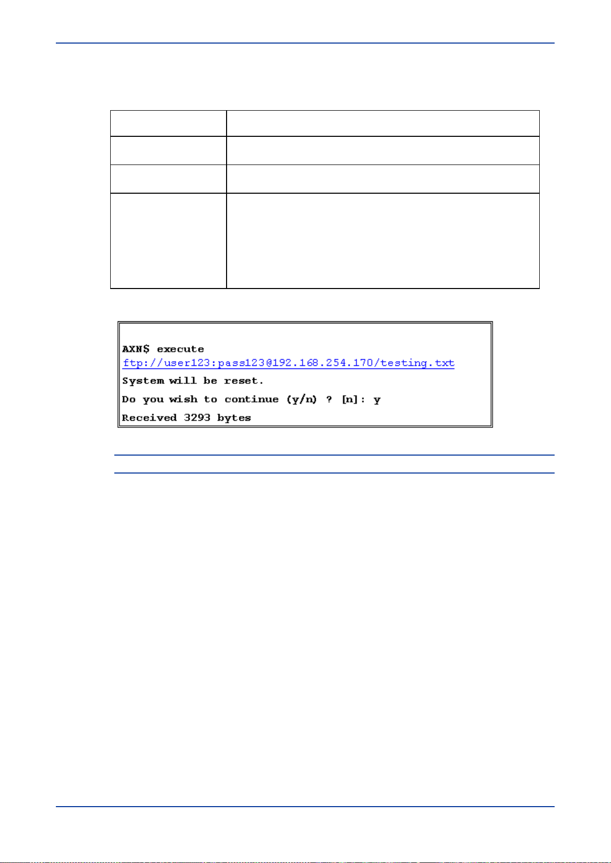
Software Download and Management
This command has the following parameters.
Table 6-2: Execute Parameters
Parameter Description
-v
-i
SourceFile
This optional parameter is for the verbose mode. Add this parameter to
display the executed script as the AXN executes the commands.
This optional parameter is for the Ignore Error mode. Add this parameter
to continue executing all the commands in the script, even if errors occur.
This parameter defines the filename and location where the source file is
stored. The syntax is similar to an URL filename and is as follows:
ftp://[<username>[:<password>]@]<ftp_server_ip>[:
port]/filepath
where;
ftp_server_ip is the address of the FTP server
Filepath is the directory path and file name of the source file
Example:
Figure 6-2: Execute ftp display
Note: After the database is restored, the AXN1/10 is reset and the new database is loaded.
6.2 Local R es tore Management
This section describes how to create a restore point to enable the device to revert to a locally
6.2.1 Purpos e
6.2.2 Command S yntax
saved configuration.
The sysConf command enables the operator to return to a previously locally saved
configuration ("restore point") in various cases, such as: risky operations, massive changes or
loss of connectivity. The device returns to the restore point upon request or lack of
communication.
At any given time a user can set a restore point.
To create a restore point use the following:
sysconf store [-d <description>]
AccessDevice AXN 1 10UGV2.9.82 6-3
Page 94

Software Download and Management
Example:
AXN10# sysConf store -d test
Creating Restore Point, please wait ...
done.
Only one restore point is available at any given time.
To display the current status of the restore point use the following:
sysconf info [-full]
Example:
AXN10# sysConf info
----------------------------------------------------------Creation date: 05/11/2008 15:25:47.620
Software Release: 2.9.2
Description: test
Restore in (minutes): 0
-----------------------------------------------------------
Reverting the configuration to the restore point can be set to be performed immediately or with a
timer.
To perform system restoration to the restore point use the following:
sysconf restore [{-in <MM>} | {-cancel}]
<MM> - schedule restoration in [5-30] minutes
Example:
AXN10# sysConf restore
The system is going to perform reset and revert to the following
Restore Point:
----------------------------------------------------------Creation date: 05/11/2008 15:25:47.620
Software Release: 2.9.2
Description: test
Restore in (minutes): 0
----------------------------------------------------------Do you wish to continue (Y/N)? [n]: y
Preparing for restoration ...
Restoring .....
AXN will be reset. Please wait for communication to restore...
To remove/clear existing restore point use the following:
sysconf erase
6-4 AccessDevice AXN 1 10UGV2.9.82
Page 95

Software Download and Management
6.3 Downloading a New S oftware Version
Use the sw load command to download a new AXN1/10 software version from an FTP
server.
This command downloads a file from the root directory of an FTP server.
The AXN can store up to three software versions (1 active and 2 stored). An error message
appears when attempting to download additional software versions.
To download a new software version:
1. Use an FTP Server application, such as 3CDaemon, to allow the remote computer to act as
an FTP server.
2. Copy the new software to any computer connected to the AXN1/10 via an IP network.
3. Save the file in the root directory of the FTP server.
Note: The AXN1/10 recognizes the software file by its filename. For the AXN1/10, the
format is Onexxxxxx.zip. For example, for version 2.6.7, the filename is
One020607.zip.
4. If the FTP server does not provide an anonymous user, at the prompt, type:
sw load
<x.x.x>ftp://[<username>[:<password>]@]<ftp_server_ip>[:port]/
filepath, where:
x.x.x - the version number of the new software, such as 2.6.6
username - username to access the FTP server
password - password to access the FTP server
ftp_server_ip - IP address of the FTP server
port - port number of the FTP server
filepath - directory path and filename where the exported file is saved
and press Enter.
The AXN1/10 downloads the new software from the remote computer. See the figure below.
For information on activating the new software, see Activating a Software Version (on page
6-6).
Figure 6-3: Downloading a New Software Version - with Username and Password
AccessDevice AXN 1 10UGV2.9.82 6-5
Page 96

Software Download and Management
Convert
clean
5. If the FTP server does provide an anonymous user, at the prompt, type: sw load
<x.x.x> <ftp_server_ip>[:port]/filepath, where:
x.x.x - the version number of the new software, such as 2.6.6
ftp_server_ip - IP address of the FTP server
port - port number of the FTP server
filepath - directory path and filename where the exported file is saved,
and press Enter.
The AXN1/10 downloads the new software from the remote computer. See the figure below.
For information on activating the new software, see Activating a Software Version (on page
6-6).
Figure 6-4: Downloading a New Software Version - without Username and Password
6.4 Activating a S oftware Version
Use the sw activate command to switch to an inactive AXN1/10 software version. Each
software version has its own database. When you activate a software version, you can choose
the action to perform on the database. The options are listed in the following table.
Caution: Activating a non-active software version causes the AXN1/10 to be reset. This will
temporarily interrupt traffic for approximately two minutes.
This is assuming that you will not need to configure the new database. That is, you are copying
the previous database, or you are activating a previous software version, which has a usable
configuration in its database.
To activate a software version:
• At the prompt, type: sw activate <x.x.x> -<DB_option> -f, where
<x.x.x> is the version number of the software, such as 2.6.6, and
<DB_option> and –f are according to the following table, and press Enter.
The software version is activated. See the figure, Software List in Displaying the Software
Version List (on page 6-7).
Table 6-3: Database Options
Database Option Description
copy
Force DB conversion (for upgrades only)
Copies the database from the previous version to the version being
activated
Clears the database of the version being activated
6-6 AccessDevice AXN 1 10UGV2.9.82
Page 97

Software Download and Management
leave
Database Option Description
leave
auto
(default option)
-f
(optional switch)
Activates the software version with its own database. When
activating a new software version, the database is empty.
Database option is selected automatically:
• When activating a newer software version (higher version
number), the AXN1/10 uses the convert option.
• When activating a previous software version (lower version
number), the AXN1/10 uses the
Executes the database command without the AXN1/10 prompting
for confirmation
6.5 Deleting a S oftware Version
Use the sw delete command to delete an inactive AXN1/10 software version from the
AXN1/10.
To delete an inactive software version:
• At the prompt, type sw delete <x.x.x>
where <x.x.x> is the version number of the software, such as 2.6.6, and press Enter.
The software version is deleted from the AXN1/10.
option.
6.6 Displaying the Software Version L ist
Use the sw list command to display a list of all software versions stored on the AXN1/10.
The list displays the software version number and the date the version was released. The active
software version is the first version displayed.
To display all software versions:
• At the prompt, type sw list and press Enter.
The software list is displayed.
Figure 6-5: Software List
6.7 R everting to F ac tory S ettings
At times you may need to revert to the default factory settings, for example, if you loose all
administrator passwords. When you revert to the default factory settings, the AXN reverts to the
default username (admin) and default password (admin).
AccessDevice AXN 1 10UGV2.9.82 6-7
Page 98

Software Download and Management
Caution: When you perform the following procedure, all AXN settings will be lost.
To revert to the default factory settings:
1. Connect to the chassis directly using a serial cable and a craft terminal.
2. Restart the AXN:
Type Reset System and press Enter.
The following message appears:
The entire system is about to perform reset.
Do you want to continue (y/n)? [n]:
3. Type y and press Enter.
The system is reset.
4. As the system is rebooting, press and hold CTRL+x.
The following message appears:
!!!!!!!!!!!!!!!!!!!!!!!!!!!!!!!!!!!!!!!!!!!!!!!!!!!!!
The 'Reset to factory settings' keystroke has been detected.
!!!!!!!!!!!!!!!!!!!!!!!!!!!!!!!!!!!!!!!!!!!!!!!!!!!!!!!!!!!!!
Press <Enter> to continue. Waiting 2 minutes ...
5. Press Enter.
The following confirmation message appears:
Please choose your action:
1. Return to regular initialization procedure
2. Reset to Factory Settings
3. Reset to Restore Point
6.7.1 R eturning to R egular Initialization Procedure
By choosing option 1 the ICP will complete the reboot process and will return to normal mode
with the current database.
• Press 1.
The following confirmation message appears:
Your selection is [1] (Waiting 2 minutes): 1
Reset to factory settings has been canceled.
The system will be restarted with the previous configuration.
Please wait...
The ICP should return to normal mode after completing the reboot.
6-8 AccessDevice AXN 1 10UGV2.9.82
Page 99

Software Download and Management
6.7.2 R es et to F ac tor y S ettings
By choosing option 2 the ICP will complete the reboot procces and will return to factory
defaults.
1. Press 2.
The following confirmation message appears:
Your selection is [1] (Waiting 2 minutes): 2
If you proceed, the entire system configuration will be lost.
Do you want to proceed (Y/N) [N] (waiting 2 minutes) : Y
2. Type y and press Enter.
The following confirmation message appears:
Resetting the system to factory settings. Please wait
The factory settings have been restored successfully.
The system will be restarted.
Please wait…
The ICP should return to standalone mode after completing the reboot.
6.7.3 R eset to R estore Point
By choosing option 3, the ICP will complete the reboot process and will upload with the
restoration point database.
1. Press 3.
The following confirmation message appears:
Your selection is [1] (waiting 2 minutes):3
The system is going to perform reset and revert
To the following Restore Point
--------------------------------------------------------------
-----------------Creation date: --/--/---- 00:00:00
Software Release: 2.9
Description: <name of restoration point>
Restore in (minutes) 0
Do you want to proceed (Y/N) [N] (waiting 2 minutes):
2. Type y and press Enter.
The following confirmation message appears:
Resetting the system to restore point please wait….
AccessDevice AXN 1 10UGV2.9.82 6-9
Page 100

Software Download and Management
Preparing for restoration…..
Restoring….
The system has been restored successfully and will be
restarted.
Please wait…
6-10 AccessDevice AXN 1 10UGV2.9.82
 Loading...