

AXELL D-MBR 3007-3008-PS NFPA REPEATER
PRODUCT DESCRIPTION AND USER’S MANUAL
SMR 700/800 Digital Multi-Channel IP65
(NEMA 4) Band Selective Repeater
PRODUCT DESCRIPTION AND USER’S MANUAL
for AXELL D-MBR 3007-3008-PS NFPA REPEATER
UMCD00013 Rev 2.2
D-MBR 3007-3008 PS NFPA
AXELL D-MBR 3007-3008-PS NFPA REPEATER
PRODUCT DESCRIPTION AND USER’S MANUAL
Copyright © 2014 Axell Wireless Ltd
All rights reserved.
No part of this document may be copied, distributed, transmitted, transcribed, stored in a retrieval system, or
translated into any human or computer language without the prior written permission of Axell Wireless Ltd.
The manufacturer has made every effort to ensure that the instructions contained in this document are adequate
and free of errors and omissions. The manufacturer will, if necessary, explain issues which may not be covered
by this document. The manufacturer's liability for any errors in the document is limited to the correction of errors
and the aforementioned advisory services.
This document has been prepared to be used by professional and properly trained personnel, and the customer
assumes full responsibility when using them. The manufacturer welcomes customer comments as part of the
process of continual development and improvement of the documentation in the best way possible from the
user's viewpoint. Please submit your comments to the nearest Axell Wireless sales representative.
Contact Information
Headquarters Axell Wireless
Aerial House
Asheridge Road, Chesham
Buckinghamshire HP5 2QD
United Kingdom
Tel: +44 1494 777000
Fax: +44 1494 777002
Commercial inquiries
Web site
Support issues
Technical Support Line, English
speaking
Contact information for Axell Wireless offices in other countries can be found on our web site,
www.axellwireless.com
info@axellwireless.com
www.axellwireless.com
support@axellwireless.com
+44 1494 777 747
II UMCD00013 Rev 2.2 © Axell Wireless Ltd

AXELL D-MBR 3007-3008-PS NFPA REPEATER
PRODUCT DESCRIPTION AND USER’S MANUAL
About This Manual
This Product Manual provides the following information:
• Description of the Repeater
• Procedures for setup, configuration and checking the proper operation of the
Repeater
• Maintenance and troubleshooting procedures
For whom it is Intended
This Product Manual is intended for experienced technicians and engineers. It is assumed
that the customers installing, operating, and maintaining Axell Wireless Mini-Repeaters
are familiar with the basic functionality of Repeaters.
Notice
Confidential - Authorized Customer Use
This document may be used in its complete form only and is solely for the use of Axell
Wireless employees and authorized Axell Wireless channels or customers. The material
herein is proprietary to Axell Wireless. Any unauthorized reproduction, use or disclosure
of any part thereof is strictly prohibited.
All trademarks and registered trademarks are the property of their respective owners.
Disclaimer of Liability
Contents herein are current as of the date of publication. Axell Wireless reserves the right
to change the contents without prior notice. The information furnished by Axell Wireless
in this document is believed to be accurate and reliable. However, Axell Wireless assumes
no responsibility for its use. In no event shall Axell Wireless be liable for any damage
resulting from loss of data, loss of use, or loss of profits and Axell Wireless further
disclaims any and all liability for indirect, incidental, special, consequential or other similes
damages. This disclaimer of liability applies to all products, publications and services
during and after the warranty period.
Guarantees
• All antennas must be installed with lightning protec
modules, as a result of lightning are not covered by the warranty.
• Antennas must be connected before switching on AC or DC power. Switching
power on prior to the connection of antenna cables is regarded as faulty installation
procedure and therefore not covered by the Axell Wireless warranty.
• The repeater box should be closed using the two screws. The screws must be
fully tightened. Failure to do so may affect the IP65 compliancy and therefore any
warranty.
tion. Damage to power
Exclusive Remedies
The remedies provided herein are the Buyer’s sole and exclusive remedies. Axell Wireless
shall not be viable for any direct, incidental, or consequential damages, whether based on
contract, tort, or any legal theory.
© Axell Wireless Ltd UMCD00013 Rev 2.2 III
AXELL D-MBR 3007-3008-PS NFPA REPEATER
PRODUCT DESCRIPTION AND USER’S MANUAL
Compliance with FCC
Note the following: This repeater can be operated as Part 90 Class A repeater.
FCC Part 90 Warning Statement
Note the following
The installation procedure must result in the signal booster complying with FCC
requirements 90.219(d). In order to meet FCC requirements 90.219(d), it may be
necessary for the installer to reduce the UL and/or DL output power for certain
installations.
WARNING: This is NOT a CONSUMER device. It is designed for installation by FCC
LICENCEES and QUALIFIED INSTALLERS. You must have an FCC LICENCE or
express consent of an FCC Licensee to operate this device.
This is a Class B signal booster. You MUST register Class B signal boosters (as
defined in 47 CFR 90.219) online at www.fcc.gov/signal-boosters/registration.
Unauthorized use may result in significant forfeiture penalties, including penalties in
excess of $100,000 for each continuing violation.
FCC Part 15
This device complies with part 15 of the FCC Rules. Operation is subject to the following
two conditions:
1. This device may not cause harmful interference, and
2. This device must accept any interference received, including interference that may
cause undesired operation.
This equipment has been tested and found to comply with the limits for a Class A digital
device, pursuant to part 15 of the FCC Rules. These limits are designed to provide
reasonable protection against harmful interference when the equipment is operated in
a commercial environment. This equipment generates, uses, and can radiate radio
frequency energy and, if not installed and used in accordance with the instruction
manual, may cause harmful interference to radio communications. Operation of this
equipment in a residential area is likely to cause harmful interference in which case the
user will be required to correct the interference at his own expense.
IV UMCD00013 Rev 2.2 © Axell Wireless Ltd
AXELL D-MBR 3007-3008-PS NFPA REPEATER
PRODUCT DESCRIPTION AND USER’S MANUAL
FCC RF Exposure Limits
This unit complies with FCC RF exposure limits for an uncontrolled environment. This
equipment can only be installed in in-building applications, driving passive or active DAS
systems. All antennas must be operated at a minimum distance of 44
radiator and any person’s body.
cm between the
Antenna Installation
Installation of an antenna must comply with the FCC RF exposure requirements. The
an
tenna used for this transmitter must be mounted on permanent structures.
Signal boosters must be deployed such that the radiated power of the each retransmitted
channel, on the forward link and on the reverse link, does not exceed 5 Watts effective
radiated power (ERP).
Therefore the max antenna gain allowed for this type of signal booster should be limited
to the values given by equation (1) for the service antenna and equation (2) for the donor
antenna
Equation (1) - Max SERVICE antenna gain
Max SERVICE antenna gain (dBi) = 37dBm[EIRP] – (33dbi – 10log(N)(dB) – cable loss in dB).
For example:
No. of Antennas Cable Losses Max Allowed Antenna Gain
4 2 37 - (33+6-2) = 0 dBd
1 2 37- (33+0-2) = 6 dBd
10 2 37- (33+10-2) = -2dBd
Note :0dBd = 2.15dBi
Equation (2) - Max DONOR antenna gain
Max DONOR antenna gain (dBi) = 37 – (27dbi - cable losses in dbi).
© Axell Wireless Ltd UMCD00013 Rev 2.2 V
AXELL D-MBR 3007-3008-PS NFPA REPEATER
PRODUCT DESCRIPTION AND USER’S MANUAL
Compliance with FCC deployment rule regarding the radiation of noise
Good engineering practice must be used in regard to the signal booster’s noise radiation.
Thus, the gain of the signal booster should be set so that the EIRP of the output noise
from the signal booster should not exceed the level of -43 dBm in 10 kHz measurement
bandwidth.
In the event that the noise level measured exceeds the aforementioned value, the signal
booster gain should be decreased accordingly.
In general, the ERP of noise on a spectrum more than 1 MHz outside of the pass band
should not exceed -70 dBm in a 10 kHz measurement bandwidth.
The 3308 signal booster has a noise level of -43 dBm in 10 kHz measurement at 1 MHz
spectrum outside the passband of the signal booster and an in-band noise level at around
-37 dBm in a 10 kHz bandwidth. Therefore, the noise at the antenna input port should be
calculated based on equation (3).
Equation (3) - Input Noise to service antenna
Input Noise to service antenna:
-43 dBm + Service Antenna gain – Antenna splitter losses in dBi – cable loss in dB
Example:
Signal booster connected to 10 service antennas with a 100m long ½ inch cable.
• Losses of such a cable with the connectors = ~ 11dB
• Gain = ~ 2 dBi
Assuming 10 service antennas: antenna splitter losses = 11 dB
Based on equation (3) Input antenna noise (to the antenna) = -43+2-11 -11=-63 dBm
The inband input noise to the antenna should be -37+2 -11-11= -57dbm
NOTE: In this example you may be required in general
attenuate by additional 7 dB the out of band noise.
Conclusion:
Good engineering practice requires that in general when the out of band noise measured
at the service antenna input is more than -70 dbm per 10 kHz measurement bandwidth,
an external band pass filter should be added to attenuate the out of band noise level.
to add an external bandpass filter that would
Compliance with IC
Under Industry Canada regulations, this radio transmitter may only operate using an
antenna of a type and maximum (or lesser) gain approved for the transmitter by Industry
Canada. To reduce potential radio interference to other users, the antenna type and its
gain should be so chosen that the equivalent isotropically radiated power (e.i.r.p.) is not
more than that necessary for successful communication.
The Manufacturer's rated output power of this equipment is for single carrier operation.
For situations when multiple carrier signals are present, the rating would have to be
reduced by 3.5 dB, especially where the output signal is re-radiated and can cause
interference to adjacent band users. This power reduction is to be by means of input
power or gain reduction and not by an attenuator at the output of the device.
VI UMCD00013 Rev 2.2 © Axell Wireless Ltd

AXELL D-MBR 3007-3008-PS NFPA REPEATER
PRODUCT DESCRIPTION AND USER’S MANUAL
This equipment complies with IC RSS-102 radiation exposure limits set forth for an
uncontrolled environment. This equipment should be installed and operated with minimum
distance of 35 cm between the antenna and your body.
Conformément à la réglementation d'Industrie Canada, le présent émetteur radio peut
fonctionner avec une antenne d'un type et d'un gain maximal (ou inférieur) approuvé pour
l'émetteur par Industrie Canada. Dans le but de réduire les risques de brouillage
radioélectrique à l'intention des autres utilisateurs, il faut choisir le type d'antenne et son
gain de sorte que la puissance isotrope rayonnée équivalente (p.i.r.e.) ne dépasse pas
l'intensité nécessaire à l'établissement d'une communication satisfaisante.
La puissance de sortie nominale indiquée par le fabricant pour cet appareil concerne son
fonctionnement avec porteuse unique. Pour des appareils avec porteuses multiples, on
doit réduire la valeur nominale de 3.5dB, surtout si le signal de sortie est retransmis et
qu'il peut causer du brouillage aux utilisateurs de bandes adjacentes. Une telle réduction
doit porter sur la puissance d'entrée ou sur le gain, et ne doit pas se faire au moyen d'un
atténuateur raccordé à la sortie du dispositif.
Cet appareil est conforme aux limitations de la norme IC RSS-102 concernant l’exposition
aux radiations dans un environnement non contrôlé. Cet appareil doit être installé et
utilisé avec une distance minimale de 30 cm entre l’antenne et le corps de l’utilisateur.
© Axell Wireless Ltd UMCD00013 Rev 2.2 VII
AXELL D-MBR 3007-3008-PS NFPA REPEATER
PRODUCT DESCRIPTION AND USER’S MANUAL
General Safety Warnings Concerning Use of This System
Always observe standard safety precautions during installation, operation and
maintenance of this product.
Throughout this manual, there are "Caution" warnings. "Caution"
calls attention to a procedure or practice, which, if ignored, may
Caution labels!
Danger: Electrical
Shock
Caution: Safety to
personnel
Caution: Safety to
equipment
result in injury or damage to the system, system component or
even the user. Do not perform any procedure preceded by a
"Caution" until the described conditions are fully understood and
met.
This equipment must be installed indoors only. . To prevent
electrical shock when installing or modifying the system power
wiring, disconnect the wiring at the power source before working
with un insulated wires or terminals.
Before installing or replacing any of the equipment, the entire
manual should be read and understood.
The user needs to supply the appropriate AC or DC power to the
repeater. Incorrect power settings can damage the repeater and
may cause injury to the user.
Please be aware that the equipment may, during certain
conditions become very warm and can cause minor injuries if
handled without any protection, such as gloves.
When installing, replacing or using this product, observe all
safety precautions during handling and operation. Failure to
comply with the following general safety precautions and with
specific precautions described elsewhere in this manual violates
the safety standards of the design, manufacture, and intended
use of this product.
Axell Wireless assumes no liability for the customer's failure to
comply with these precautions. This entire manual should be read
and understood before operating or maintaining the repeater.
Access to the Axell unit installation location is restricted to
Warning: Restricted
Access Location
Attention:
Electrostatic
Sensitivity
VIII UMCD00013 Rev 2.2 © Axell Wireless Ltd
SERVICE PERSONNEL and to USERS who have been instructed on
the restrictions and the required precautions to be taken.
Observe electrostatic precautionary procedures.
ESD = Electrostatic Discharge Sensitive Device.
Semiconductor transmitters and receivers provide highly reliable
performance when operated in conformity with their intended
design. However, a semiconductor may be damaged by an
electrostatic discharge inadvertently imposed by careless
handling.
Static electricity can be conducted to the semiconductor chip
from the centre pin of the RF input connector, and through the
AC connector pins. When unpacking and otherwise handling the
repeater, follow ESD precautionary procedures including use of
grounded wrist straps, grounded workbench surfaces, and
grounded floor mats.

AXELL D-MBR 3007-3008-PS NFPA REPEATER
PRODUCT DESCRIPTION AND USER’S MANUAL
Table of Contents
1 Introduction .................................................................................................................................. 1
1.1 Main Features ........................................................................................................................ 2
1.2 Repeater Model ...................................................................................................................... 3
1.3 NFPA Installation Architecture ............................................................................................... 3
1.4 Smart-ALC Function ............................................................................................................... 4
1.5 Interfaces ................................................................................................................................ 4
1.6 Navigating the Web GUI Application ...................................................................................... 5
1.6.1 Topology Tree Branches ........................................................................................... 5
1.6.2 Operation Buttons ..................................................................................................... 6
1.6.3 Band Pane and Tabs ................................................................................................. 6
1.6.4 CMU Pane and Tabs ................................................................................................. 7
2 Antenna Installation Requirements ........................................................................................... 8
2.1 Base (Donor) Antenna Requirements .................................................................................... 8
2.1.1 Required Antenna Information .................................................................................. 8
2.1.2 Donor Antenna Specifications ................................................................................... 8
2.1.3 Installation Criteria ..................................................................................................... 8
2.2 Service Antenna Requirements ............................................................................................. 9
2.2.1 Required Information ................................................................................................. 9
2.2.2 Indoor Antenna Installations ...................................................................................... 9
2.2.3 Outdoor Installations ............................................................................................... 10
3 Installing the Repeater .............................................................................................................. 13
3.1 Repeater Pre-Installation Requirements .............................................................................. 13
3.1.1 Safety Guidelines .................................................................................................... 13
3.1.2 Required BTS Information ....................................................................................... 13
3.1.3 Installation Location and Environment .................................................................... 13
3.1.4 RF Cable Installation Guidelines ............................................................................. 14
3.1.5 Grounding Wires Requirements .............................................................................. 14
3.2 Overview of the Installation Procedure ................................................................................ 14
3.3 Unpacking ............................................................................................................................ 15
3.4 Mounting the D-MBR ............................................................................................................ 16
3.4.1 Pre-Mounting Procedure ......................................................................................... 16
3.4.2 Installing the Mounting Bracket ............................................................................... 17
3.4.3 Preparing Power Supply Cables ............................................................................. 17
3.4.4 Mounting the Repeater ............................................................................................ 18
3.5 Grounding ............................................................................................................................. 20
3.6 Before Connecting Antennas or Powering On! .................................................................... 20
3.6.1 Verifying Isolation between Donor and Mobile Antennas ....................................... 20
3.6.2 Verifying the Link between the BTS and the Repeater ........................................... 21
3.7 Antenna Connections ........................................................................................................... 21
3.8 Powering Up the D-MBR ...................................................................................................... 22
3.8.1 Standard Power Connection ................................................................................... 22
3.8.2 D-MBR-PS NFPA Power Connection...................................................................... 23
3.9 Alarm Connections ............................................................................................................... 23
3.9.1 Alarm Connector Pinout .......................................................................................... 24
3.9.2 Load Restrictions ..................................................................................................... 24
3.9.3 Summary Alarms Trigger Criteria ............................................................................ 25
3.9.4 D-MBR-PS-NFPA Installation Alarm Connections .................................................. 25
IX UMCD00013 Rev 2.2 © Axell Wireless Ltd

AXELL D-MBR 3007-3008-PS NFPA
PRODUCT DESCRIPTION AND USER’S MANUAL
4 Initial Setup and Commissioning ............................................................................................. 26
4.1 Open a Session to the Repeater .......................................................................................... 26
4.1.1 Connect the Repeater to the Computer .................................................................. 26
4.1.2 Configure the Computer Network Parameters ........................................................ 26
4.1.3 Login to the Repeater .............................................................................................. 29
4.2 Configuring RF Parameters and Channels .......................................................................... 30
4.2.1 Control Params Tab ................................................................................................ 30
4.3 Setting Date and Time.......................................................................................................... 34
4.4 Configuring the External Alarms .......................................................................................... 35
4.5 Setting the IP Address.......................................................................................................... 36
5 Administrative Operations ........................................................................................................ 37
5.1 User Management ................................................................................................................ 37
5.1.1 User Levels .............................................................................................................. 37
5.1.2 Viewing the List of Defined Users ........................................................................... 37
5.1.3 Adding Users ........................................................................................................... 38
5.1.4 Editing a User .......................................................................................................... 38
5.1.5 Deleting a User ........................................................................................................ 38
5.2 Repeater and Band Level Information ................................................................................. 39
5.2.1 Viewing Repeater Level Information ....................................................................... 39
5.2.2 Viewing Band Level Info .......................................................................................... 39
5.3 Configuration Files Backup/Restore ..................................................................................... 40
5.3.1 The Backup/Restore Tab ........................................................................................ 41
5.3.2 Backup of Repeater Configuration .......................................................................... 42
5.3.3 Restoring Previous Repeater Configuration ............................................................ 42
5.3.4 Uploading New Configuration File to Repeater ....................................................... 43
5.3.5 Saving Configuration File to Computer ................................................................... 43
5.4 CMU Software Upgrade ....................................................................................................... 44
6 Monitoring and Troubleshooting.............................................................................................. 47
6.1 Front Panel LED ................................................................................................................... 47
6.2 GUI Alarm Descriptions ........................................................................................................ 48
6.3 Alarms Log ........................................................................................................................... 50
Appendix A: Specifications .......................................................................................................... 51
X UMCD00013 Rev 2.2 © Axell Wireless Ltd
AXELL D-MBR 3007-3008-PS NFPA REPEATER
PRODUCT DESCRIPTION AND USER’S MANUAL
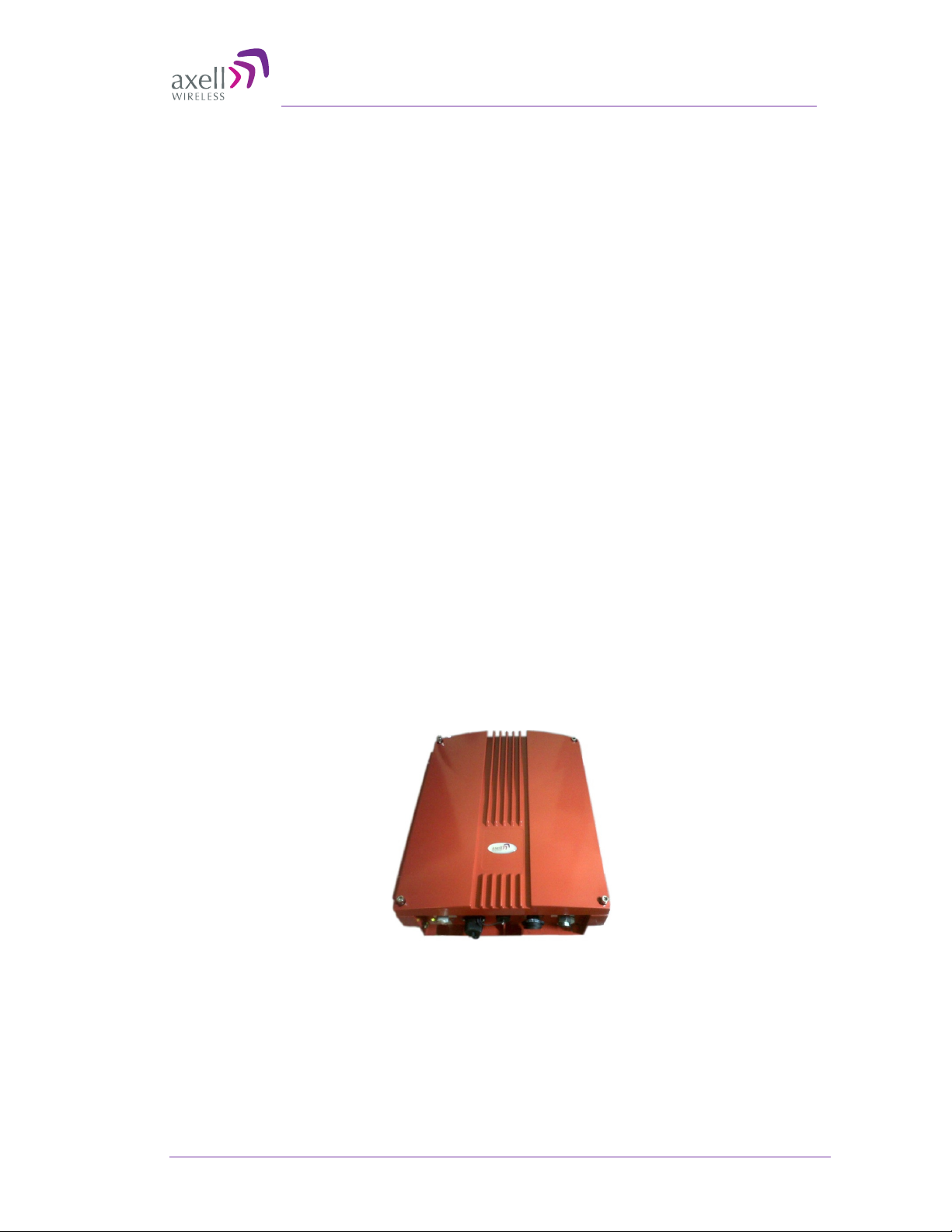
1 Introduction
D-MBR 3007-3008 PS NFPA (Digital Multi Band Repeater for Public Safety) is a high-power
digital multi-channel signal booster (DCSB). It features an array of up to 12 DSP based,
software-controlled, variable bandwidth filters, that are user-programmable across the
700 and 800 MHz bands.
D-MBR 3007-3008 PS NFPA supports all public safety technologies. For each filter, the
user can specify the start and stop frequencies with different options varying in time delay
and filter slope. This allows the engineer to trade off adjacent channel rejection and time
delay interference against a wider coverage area, permitting D-MBR 3007-3008 PS NFPA
usage in applications where no other booster solution will work.
Every parameter of D-MBR 3007-3008 PS NFPA, including filter tuning and selection, can
be controlled via web based management. The patented Axell Wireless’ digital RF filter
enables simple initial setup for any channel plan and if necessary, allows some basic
reconfiguration due to re-banding.
SALC-Smart ALC mechanism to protect the digital signal booster from oscillation and
shutdown the signal booster when required.
With the NFPA option, this Axell product meets the rigid requirements as defined by the
NFPA and International Fire Code developmental organizations. The amplifier meets
NEMA4 compliance for hose-down and provides all Alarming outputs as defined by NFPA
2010, Chapter 24, including system and antenna failures.
Axell also offers the following options to meet additional code compliance needs:
• 12 or 24 hour compliant UPS back up – meets NEMA 4 a
• External Phone Dialer – meets NEMA 4 and allows Dial-out to paging devices when
an alarm is triggered
• Outer casing is painted Fire Life Safety Red
nd alarming requirements
© Axell Wireless Ltd UMCD00013 Rev 2.2 1
D-MBR 3007-3008 PS NFPA

AXELL D-MBR 3007-3008-PS NFPA REPEATER
PRODUCT DESCRIPTION AND USER’S MANUAL
1.1 Main Features
• Class A or B- signal booster ( based on filter setting) for SMR and public safety
networks
• Supports APCO 25 phase 1 and 2 for public safety networks
• NFPA 72-2010, Chapter 24 and IFC 510.1 Compliant
• Support of 700MHz D block for LTE network
• SMR 700MHz and 800MHz bands in a single enclosure
• RF Gain: Up to 85dB Gain
• SALC-Smart ALC mechanism to protect the digital signal booster from oscillation
and shutdown the signal booster when required
• Output Power per band: DL +30dBm; UL +24dBm
• Composite Output Power: DL +33dBm; UL +27dBm
• Web based management GUI, SNMP traps
• Patented DSP filtering™ technology
• Supports up to 12 independent filters; user programmable bandwidth /
frequency
• For SMR700: Programmable 12.5 kHz to 17MHz
• For SMR800: Programmable 12.5 kHz to 10MHz
• User-selectable adjacent channel rejection and time delay to minimize
interference
• IP65 (NEMA 4) Enclosure
2 UMCD00013 Rev 2.2 © Axell Wireless Ltd
Axell D-MBR 3007-3008-PS-NFPA
PRODUCT DESCRIPTION AND USER’S MANUAL
1.2 Repeater Model
ORDERING INFORMATION
Identification Description Part Number
D-MBR 3007-3008
PS NFPA AC
D-MBR 3007-3008
PS NFPA DC
Digital Multi Channel Selective Repeater
700/800 12 channels,
30 dBm output power per band, 85 dB
gain, AC powering with NFPA and IFC
compliant Alarm Outputs, Red colored
case
Digital Multi Channel Selective Repeater
700/800 12 channels,
30 dBm output power per band, 85 dB
gain, DC powering with NFPA and IFC
compliant Alarm Outputs, Red colored
case
D-MBR 7/8 PS
30DBM 12 FIL NFPA
RED
D-MBR 7/8 PS
30DBM 12F NFPA DC
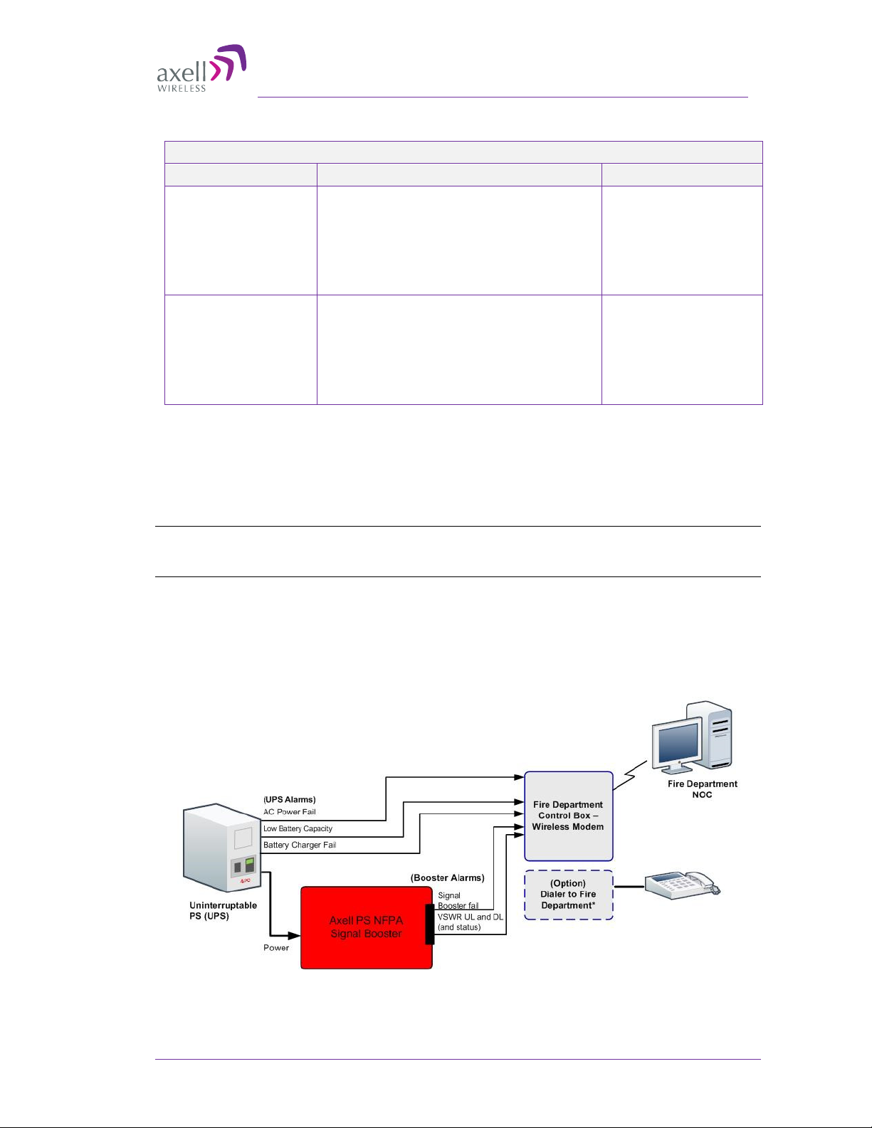
1.3 NFPA Installation Architecture
To meet the National Fire Protection Association (NFPA) requirements, power to the
Repeater is provided via a UPS and the status of the UPS, Repeater and DAS system
(antennas) is monitored via alarm connections to the Fire Department Control Box.
NOTE: An alternative to the Fire Department Control Box connections is to connect the D-MBR PS
NFPA and UPS dry contact alarms to an Automatic Dialer. Axell Wireless recommends the AD-2000
Automatic Voice/Pager Dialer System.
The alarms are connected as follows:
• From the UPS - the power indicator alarms are connected directly to the Fire
Department Control Box.
• From the Repeater – the Repeater status and antenna status alarms are connected
to the Control Box
igure 1-1. D-MBR PS NFPA Architecture
F
© Axell Wireless Ltd UMCD00013 Rev 2.2 3
AXELL D-MBR 3007-3008-PS NFPA REPEATER
DC Power
and
PRODUCT DESCRIPTION AND USER’S MANUAL
1.4 Smart-ALC Function
The Repeater’s power amplifier includes power-monitoring circuits with Automatic Level
Control (ALC) that prevents excessive output power while maintaining the power amplifier
linearity
The Smart Automatic Level Control (Smart-ALC) is an innovative algorithm for automatic
Repeater gain adjustment. Combined with advanced control algorithms, S-ALC is capable
of learning the traffic load characteristics and adjusting the Repeater RF Gain to the
desired value. Smart-ALC effectively reduces isolation problems.
NOTE: To reset the Repeater to its highest set gain value, disconnect the Repeater power cable for
several seconds and re-connect.
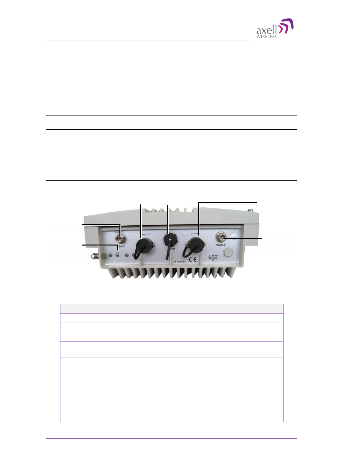
1.5 Interfaces
All the Repeater interfaces are located on the units’ underside panel. The following figure
shows the interfaces on the D-MBR.
NOTE: The NFPA unit is colored RED.
Donor antenna
connections
DL
Power LEDs
1-2. Axell D-MBR 3007-3008-PS NFPA Front Panel Interfaces
The following table provides a description of the front panel ports and connections.
Interface Description
Base Connection to Base (donor) side antenna
Mobile Connection to mobile (service) side antenna
Ethernet Connection to Ethernet devices.
Dry contact
NFPA alarms
DC Power Model dependant:
LED - Steady Green – Normal operation
Dry contact
NFPA alarms
See section 3.9 for description of alarm connections.
• Power from system AC to DC converter mounted on the
wall mount bracket. Do not connect directly to any other
power supply!!!
• Power from system DC source.
- Red or Orange - see section 6.1Error! Reference source
not found.
Ethernet
Service
antenna
connections
4 UMCD00013 Rev 2.2 © Axell Wireless Ltd
Axell D-MBR 3007-3008-PS-NFPA
Tree
Pane related to
tab
Tabs related to
Tree
PRODUCT DESCRIPTION AND USER’S MANUAL
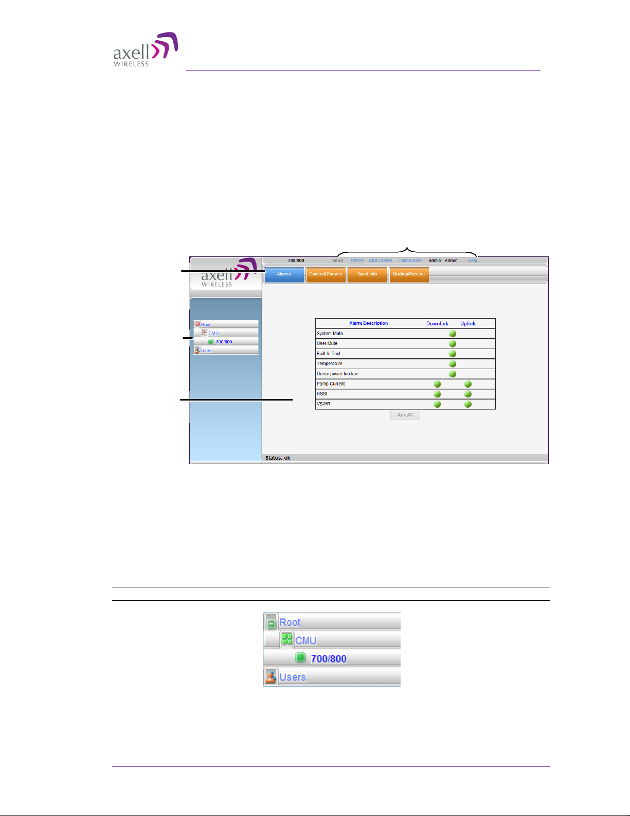
1.6 Navigating the Web GUI Application
This section describes how to navigate the Web Management application. The Web Access
interface provides the following groups of options:
• Topology Tree – provides access to unit level and ba
• Tabs – Band and unit (CMU) level options corresponding to the selected tree item
• Operation buttons – control and management options
The operation buttons at the top are common to all tree items and menus.
selected
item
nd level options
Operation buttons
selected
Figure 1-3. Web GUI Overview
1.6.1 Topology Tree Branches
The Topology Tree displays:
• CMU – Communication parameters
• 700/800 - Repeater configuration and monitoring options
• Users - User management options
NOTE: The items in the Tree Pane display the color of the most severe alarm.
Figure 1-4. Topology Tree
© Axell Wireless Ltd UMCD00013 Rev 2.2 5
AXELL D-MBR 3007-3008-PS NFPA REPEATER
PRODUCT DESCRIPTION AND USER’S MANUAL
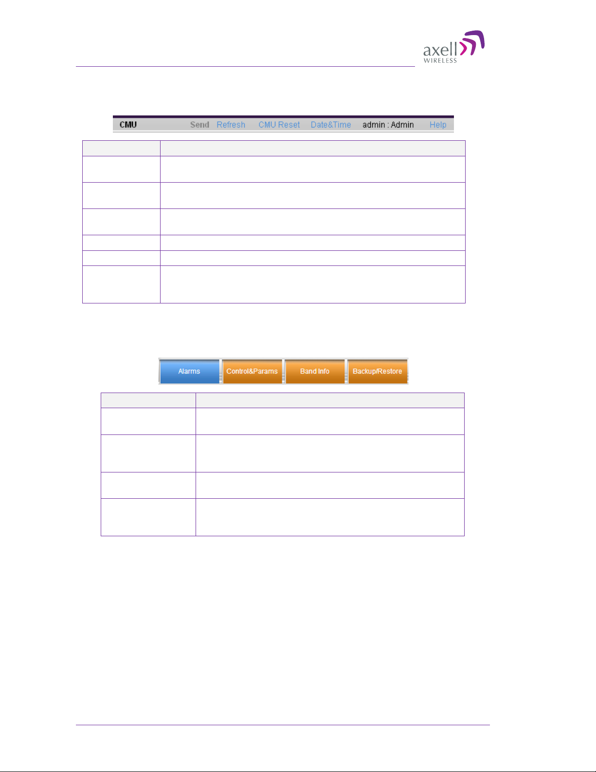
1.6.2 Operation Buttons
The following Operation buttons are available.
Item Description / Values
Send Click to save changes – before exiting the screen; otherwise,
changes will not be saved.
Refresh Click to refresh the current screen and update the displayed
data
CMU Reset Click to reset the Web Access application. Use in case of failure
or display problems
Date and Time Used to set the Repeater clock.
Admin: Admin Shows the current access level.
Help Click Help to display an e-guide line for the system operation.
This Help is general by its nature and some features may not
be included.
1.6.3 Band Pane and Tabs
The upper area of each selected pane shows the tabs corresponding to that pane.
Item Description / Values
Alarms Displays various alarms generated by the Repeater and
enables monitoring. See section 6.2.
Control and
Params
Band Info Shows information on the current band. See
Backup and
Restore
Used for adjusting RF parameters and channel
configuration (signal level, gain and bandwidth). See
section 4.2.
section 5.2.2
Configuration files management options (configuration
files can be stored on the Repeater for access). See
section 5.3.
6 UMCD00013 Rev 2.2 © Axell Wireless Ltd
Axell D-MBR 3007-3008-PS-NFPA
PRODUCT DESCRIPTION AND USER’S MANUAL
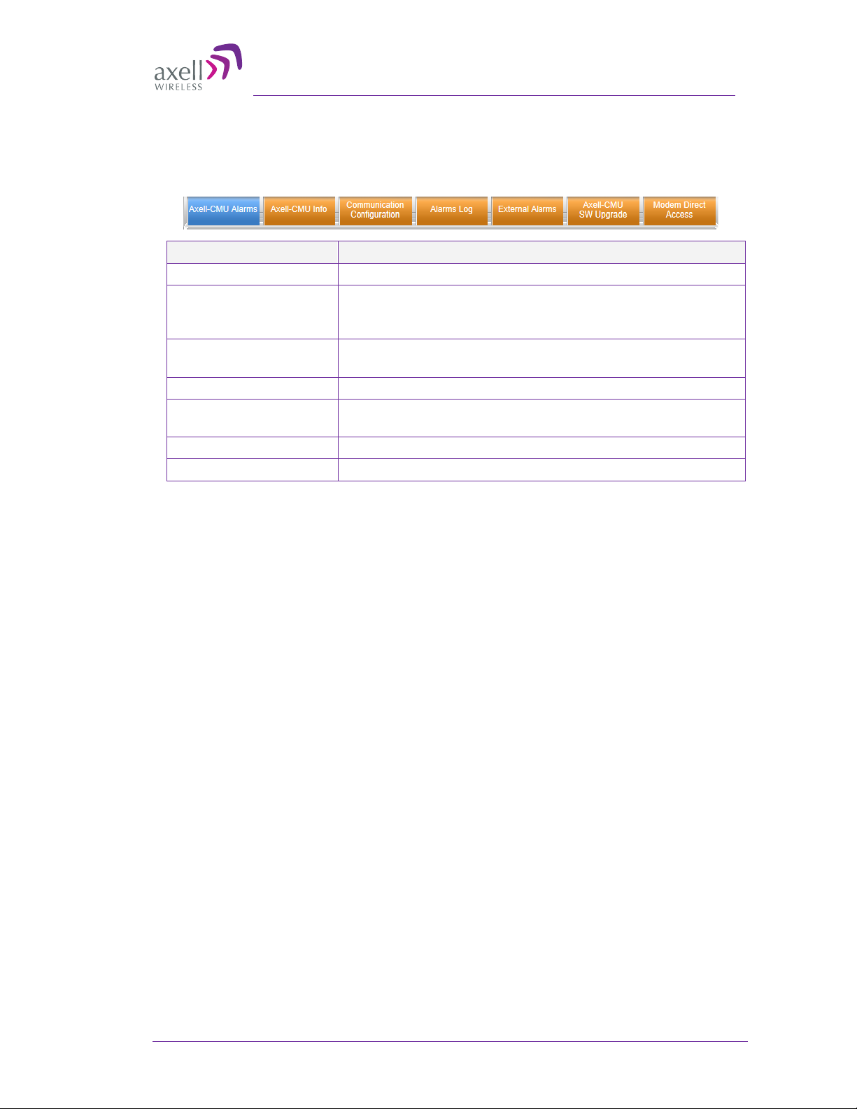
1.6.4 CMU Pane and Tabs
CMU Topology Tree menu items.
Item Description / Values
Axell-CMU Alarms Shows any generated external alarms .
Axell CMU Info Shows Repeater level information such as SW and HW
versions and identification number. In addition, enables
setting minimum alarm levels. See section 5.2.1
Communication
Configuration
Alarms Log Log of past and current alarms. See section 6.3
External Alarms Used to define any connected external alarms. See
Axell-CMU SW Upgrade Options for CMU software upgrade. See section 5.4.
Modem Direct Access N/A
Used to set communication parameters. See section 4.5.
section 4.4.
© Axell Wireless Ltd UMCD00013 Rev 2.2 7

AXELL D-MBR 3007-3008-PS NFPA REPEATER
PRODUCT DESCRIPTION AND USER’S MANUAL
2 Antenna Installation Requirements
This chapter provides information on the specifications of the donor and service antennas
suitable for operation with this repeater, on the installation requirements of the antennas
and on the Repeater installation site and cable requirements.
ATTENTION!!
The BSR-3308 models described in this manual have been approved by Industry Canada
to operate with the antenna types listed below with the maximum permissible gain and
required antenna impedance for each antenna type indicated. Antenna types not included
in this list, having a gain greater than the maximum gain indicated for that type, are
strictly prohibited for use with this device.
Le présent émetteur radio (identifier le dispositif par son numéro de certification ou son
numéro de modèle s'il fait partie du matériel de catégorie I) a été approuvé par Industrie
Canada pour fonctionner avec les types d'antenne énumérés ci-dessous et ayant un gain
admissible maximal et l'impédance requise pour chaque type d'antenne. Les types
d'antenne non inclus dans cette liste, ou dont le gain est supérieur au gain maximal
indiqué, sont strictement interdits pour l'exploitation de l'émetteur.
2.1 Base (Donor) Antenna Requirements
The Base (Donor) antenna is usually installed outdoors and is either a directional antenna
such as a Yagi or a Panel antenna.
2.1.1 Required Antenna Information
You will require the following antenna information
• Antenna type and characteristics
• Height
• Length and type of coaxial cable required for connecting the Donor antenna to the
Repeater and the attenuation.
2.1.2 Donor Antenna Specifications
• Max DONOR antenna gain (dBi) = 37 – (27dbi - cable losses in dbi).
• Very sharp beam pointed to the BTS.
• Minimum cable and jumper loss = 2dB.
2.1.3 Installation Criteria
Installation requirements:
• Verify the Donor antenna location provides a line-of-sight to the Base Station and
maximum input power.
• Install the Donor Antenna at the designated height.
Install the donor antenna at a higher level (i.e. floor) than the mobile antenna.
•
• Must be installed at a minimum distance of 30 cm for indoor applications from any
personnel within the area.
8 UMCD00013 Rev 2.2 © Axell Wireless Ltd
Axell D-MBR 3007-3008-PS-NFPA
PRODUCT DESCRIPTION AND USER’S MANUAL
2.2 Service Antenna Requirements
The Service antenna type depends on whether the Repeater is installed indoors or outdoors.
WARNINGS!!!
• The installer is held accountable for implementing the rules required
2.2.1 Required Information
The following antenna requirements, specifications and site considerations should be met:
• Type of installation – indoor only
• Service area type and size and characteristics
• Height
• Length and type of coaxial cable required for connecting the antenna to the Repeater
and the attenuation.
for deployment.
Good engineering practice must be used to avoid interference.
•
• Output power should be reduced to solve any IMD interference issues.
2.2.2 Indoor Antenna Installations
2.2.2.1 Recommended Antennas
The following describes the requirements for an omni-directional mobile used for indoor
applications.
Specifications:
One or a combination of the following antennas can be used: Ceiling Mount Patch
•
antenna, Wall Mount Patch antenna, Corner Reflector.
• Choose an antenna with high side lobe attenuation which enables maximum
isolation.
• Maximum antenna gain for indoor operation 2.2dBi.
• Cable and jumper loss is at least 2dB.
• [Gain Antenna – Cable loss] should not exceed 0.2 dB
© Axell Wireless Ltd UMCD00013 Rev 2.2 9
 Loading...