

Page 1

OMU
Optical Master Unit
© Axell Wireless Ltd
Page 2

Optical Master Unit
PRODUCT DESCRIPTION AND USER’S MANUAL
Optical Master Unit, OMU
Product Description and User’s Manual
This manual is valid for Firmware release version
Common Commands and Attributes v 1.3.0
OMU Commands and Attributes v 1.0.0
Copyright © 2009 Axell Wireless Ltd
All rights reserved.
No part of this document may be copied, distributed, tran smitted, trans cribed, stored i n a retrieval sy stem, or
translated into any human or computer language without the prior written permission of Axell Wireless Ltd.
The manufacturer has made every effort to ensure that the instructions contained in this document are
adequate and free of errors and omissions. The manufacturer will, if necessary, explain issues w hich may not
be covered by this document. The manufacturer's liability for any errors in the document is limited to the
correction of errors and the aforementioned advisory services.
This document has been prepared to be used by professional and properly trained personnel, and the
customer assumes full responsibility when usi ng them. The manufacturer welcomes customer comments as
part of the process of continual development and improvement of th e documentation i n the best way poss ible
from the user's viewpoint. Please submit your comments to the nearest Axell Wireless sales representative.
© Axell Wireless Ltd A1829300 rev H 1 (86)
Page 3

Optical Master Unit
PRODUCT DESCRIPTION AND USER’S MANUAL
Table of Contents
Safety Instructions and Warnings.................................................................................................. 4
References..................................................................................................................................... 5
Contact Information....................................................................................................................... 4
Definitions, Abbreviations and Acronyms ................................................................................... 7
1 Repeater Technology................................................................................................................ 10
1.1 Basic Repeater Features .................................................................................................... 10
1.2 Software Overview............................................................................................................ 10
2 Product and System Description..............................................................................................12
2.1 Overview........................................................................................................................... 12
2.2 Building Blocks................................................................................................................. 16
2.3 Block Diagram .................................................................................................................. 24
2.4 Back Panel......................................................................................................................... 25
2.5 Radio Signal and Data Communication Paths................................................................... 26
3 Monitoring and Control........................................................................................................... 27
3.1 Software Features - Overview........................................................................................... 27
3.2 Network Nodes.................................................................................................................. 28
3.3 Fibre Loss Compensation and Master Volume..................................................................30
3.4 Alarm System.................................................................................................................... 31
3.5 OMU Heartbeat................................................................................................................. 43
3.6 Hardware Identification..................................................................................................... 51
3.7 ID and TAG....................................................................................................................... 51
3.8 User Access....................................................................................................................... 52
3.9 Integration into AEM ........................................................................................................ 53
3.10 Upgrading Firmware ......................................................................................................... 53
4 Installation................................................................................................................................. 54
4.1 Unpack the OMU .............................................................................................................. 54
4.2 Mount the OMU................................................................................................................ 54
4.3 Ensure Proper Grounding.................................................................................................. 54
4.4 Attach Cabling................................................................................................................... 55
4.5 Start-up the OMU.............................................................................................................. 59
4.6 Initiate Local Communication........................................................................................... 61
4.7 Configure the OMU........................................................................................................... 62
4.8 Set Up OMU-Repeater System.......................................................................................... 63
4.9 Balance the System ........................................................................................................... 66
4.10 Initiate Fibre Loss Compensation...................................................................................... 68
4.11 Set up Remote Communication......................................................................................... 71
4.12 Integrate into the AEM...................................................................................................... 82
© Axell Wireless Ltd A1829300 rev H 2 (86)
Page 4

Optical Master Unit
PRODUCT DESCRIPTION AND USER’S MANUAL
4.13 Installation Examples ........................................................................................................ 83
5 Maintenance.............................................................................................................................. 85
5.1 General.............................................................................................................................. 85
5.2 Preventive Maintenance.................................................................................................... 85
5.3 Product Disposal................................................................................................................ 85
6 Specifications............................................................................................................................. 86
© Axell Wireless Ltd A1829300 rev H 3 (86)
Page 5
Optical Master Unit
PRODUCT DESCRIPTION AND USER’S MANUAL
Safety Instructions and Warnings
Guarantees
All antennas must be installed with Lightning protection. Damage to power modules, as a result of lightning are
not covered by the warranty.
Switching on AC or DC power prior to the connection of antenna cables is regarded as faulty installation
procedure and therefore not covered by the Axell Wi rel ess warranty.
Safety to Personnel
Before installing or replacing any of the equipment, the entire manual should be read and understood. The user
needs to supply the appropriate AC or DC power to the OMU System. Incorrect power settings can damage the
OMU System and may cause injury to the user.
Throughout this manual, there are "Caution" warnings. "Caution" calls attention to a procedure or practice,
which, if ignored, may result in injury or damage to the system, system component or even the user. Do not
perform any procedure preceded by a "Caution" until the described conditions are fully understood and met.
Caution
This notice calls attention to a procedure or practice that, if ignored,
may result in personal injury or in damage to the system or system component.
Do not perform any procedure preceded by a "Caution" until described
conditions are fully understood and met.
Safety to Equipment
When installing, replacing or using this product, observe all safety precautions during handling and operation.
Failure to comply with the safety precautions and with specific precautions described elsewhere in this manual
violates the safety standards of the design, manufacture, and intended use of this product. Axell Wireless
assumes no liability for the customer's failure to comply with these precautions. This entire manual should be
read and understood before operating or mainta ini n g the O M U Syst em.
Class 1 Laser
This product is equipped with class 1 lasers, as per definition in EN 60825-1.
Caution
Un-terminated optical receptacles may
emit laser radiation. Do not stare into beam
or view with optical instruments.
Optical transmitters in the opto module can emit high energy invisible laser radiation. There is a risk for
permanent damage to the eye.
Always use protective cover on all cables and connectors which are not connected. Never look straight into a
fibre cable or a connector. Consider that a fibre can carry transmission in both directions.
During handling of laser cables or connections ensure that the source is switched off. Regard all open
connectors with respect and direct them in a safe direction and never towards a reflecting surface. Reflected
laser radiation should be regarded as equally hazardous as direct radiation.
© Axell Wireless Ltd A1829300 rev H 4 (86)
Page 6

Optical Master Unit
PRODUCT DESCRIPTION AND USER’S MANUAL
Electrostatic Sensitivity
Observe electrostatic precautionary procedures.
Caution
ESD = Electrostatic Discharge Sensitive Device
Semiconductor transmitters and receivers provide highly reliable performance when operated in conformity
with their intended design. However, a semiconductor may be damaged by an electrostatic charge inadvertently
imposed by careless handling.
Static electricity can be conducted to the semiconductor chip from the centre pin of the RF input connector, and
through the AC connector pins. When unpacking and otherwise handling the OMU, follow ESD precautionary
procedures including use of grounded wrist straps, grounded workbench surfaces, and grounded floor mats.
© Axell Wireless Ltd A1829300 rev H 5 (86)
Page 7

Optical Master Unit
PRODUCT DESCRIPTION AND USER’S MANUAL
References
References to standards apply as relevant to the repeater type being connected to the OMU. Please see
respective repeater manual for details.
© Axell Wireless Ltd A1829300 rev H 6 (86)
Page 8

Optical Master Unit
PRODUCT DESCRIPTION AND USER’S MANUAL
Contact Information
Headquarters Axell Wireless
Aerial House
Asheridge Road
Chesham
Buckinghamshire HP5 2QD
United Kingdom
Tel: +44 1494 777000
Fax: +44 1494 777002
Commercial inquiries
Web site
Support issues
Technical Support Line, English speaking +44 1494 777 777
Contact information for Axell Wireless offices in other countries can be found on our web site,
www.axellwireless.com
info@axellwireless.com
www.axellwireless.com
support@axellwireless.com
© Axell Wireless Ltd A1829300 rev H 7 (86)
Page 9

Optical Master Unit
PRODUCT DESCRIPTION AND USER’S MANUAL
Definitions, Abbreviations and Acronyms
AEM Axell Element Manager
A software tool for operation and monitoring a network consisting of Axell Wireless
elements such as OMUs and repeaters.
ALC Automatic Limit Control
BCCH Broadcast Control Channel
BTS Base Transceiver Station, one part of a base station.
A base station is composed of two parts, a Base Transceiver Station (BTS) and a Base
Station Controller (BSC). A base station is often referred to as BTS.
The BTS is also sometimes called an RBS or Remote Base Station.
Channel In all Axell Wireless documentation a channel is the same as a carrier.
Channel
Selective
Repeater
DL Downlink, RF signals transmitted from base stations to mobile radio equipment
EMC Electromagnetic Compatibility
GND Ground
LED Light Emitting Diode
LMT Local Maintenance Terminal
LNA Low Noise Amplifier
MS Mobile Station (e.g. mobile phone)
MTBF Meantime Between Failures
NA Not Applicable
NC Not Connected
NF Noise Figure
NMS Network Management System
A repeater that operate on a specified channel within the operating band of the
repeater.
The ability of a device or system to function in its intended electromagnetic
environment
Node In this manual a node is the OMU or a rep eater
ODF Optical Distribution Frame, used for connection and patching of optical cables
OMC Operations and Main tenance Center
PSTN Public Service Telephone Network
Repeater
RF Radio Frequency, 9 kHz – 300 GHz
© Axell Wireless Ltd A1829300 rev H 8 (86)
A bi-directional Radio Frequency (RF) amplifier that can amplify and transmit a
received Mobile Station (MS) signal in the MS transmit band. Simultaneously it
amplifies and transmits a received Base Transceiver Station (BTS) RF signal in the
BTS transmit band.
Page 10

Optical Master Unit
PRODUCT DESCRIPTION AND USER’S MANUAL
Designation Abbreviation Frequencies
Very Low Frequency VLF 9 kHz - 30 kHz
Low Frequency LF 30 kHz - 300 kHz
Medium Frequency MF 300 kHz - 3 MHz
High Frequency HF 3 MHz - 30 MHz
Very High Frequency VHF 30 MHz - 300 MHz
Ultra High Frequency UHF 300 MHz - 3 GHz
Super High Frequency SHF 3 GHz - 30 GHz
Extremely High Frequency EHF 30 GHz - 300 GHz
RMC Repeater Maintenance Console
Software tool to monitor and control Axell Wireless repeaters.
RS232 Serial interface standard
RS485 Serial Interface standard
SIM Subscriber Iden tity Module
SMS Short Messaging Service
SMSC Short Messaging Service Center
SW Software
UE User Equipment
UL Uplink, RF signals transmitted from mobile radio equipment to a base station
WDM Wavelength Division Multiplexing
© Axell Wireless Ltd A1829300 rev H 9 (86)
Page 11
Optical Master Unit
PRODUCT DESCRIPTION AND USER’S MANUAL
1 Repeater Technology
1.1 Basic Repeater Features
A basic feature of a mobile communication system is to transmit RF signals between base stations and mobile
radio equipment.
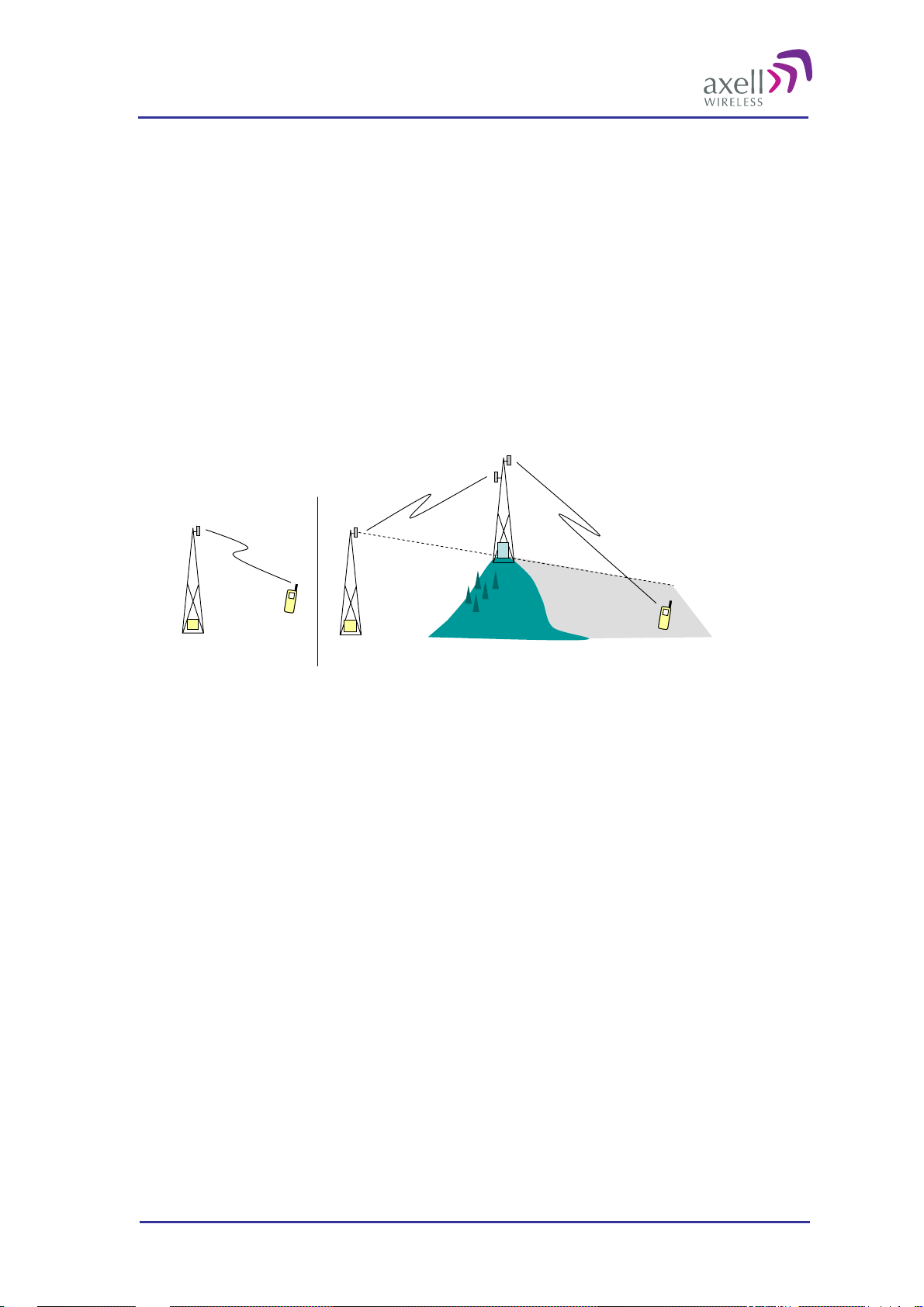
When there is a blocking object, such as a mountain or a building, preventing the base station signal to reach the
mobile equipment, a repeater can be used to extend the base station’s coverage area.
In the downlink path (from the base station to the mobile phone) the repeater picks up the signal in the air via a
donor antenna, amplifies it and re-transmits it into the desired coverage area via a server antenna. In the uplink
path (from the mobile phone to the base station) the repeater receives the signals from mobile transmitters in the
covered area and re-transmits them back to the base station.
Donor antenna
BTS
Undisturbed transmission Obstacle creating a coverage hole
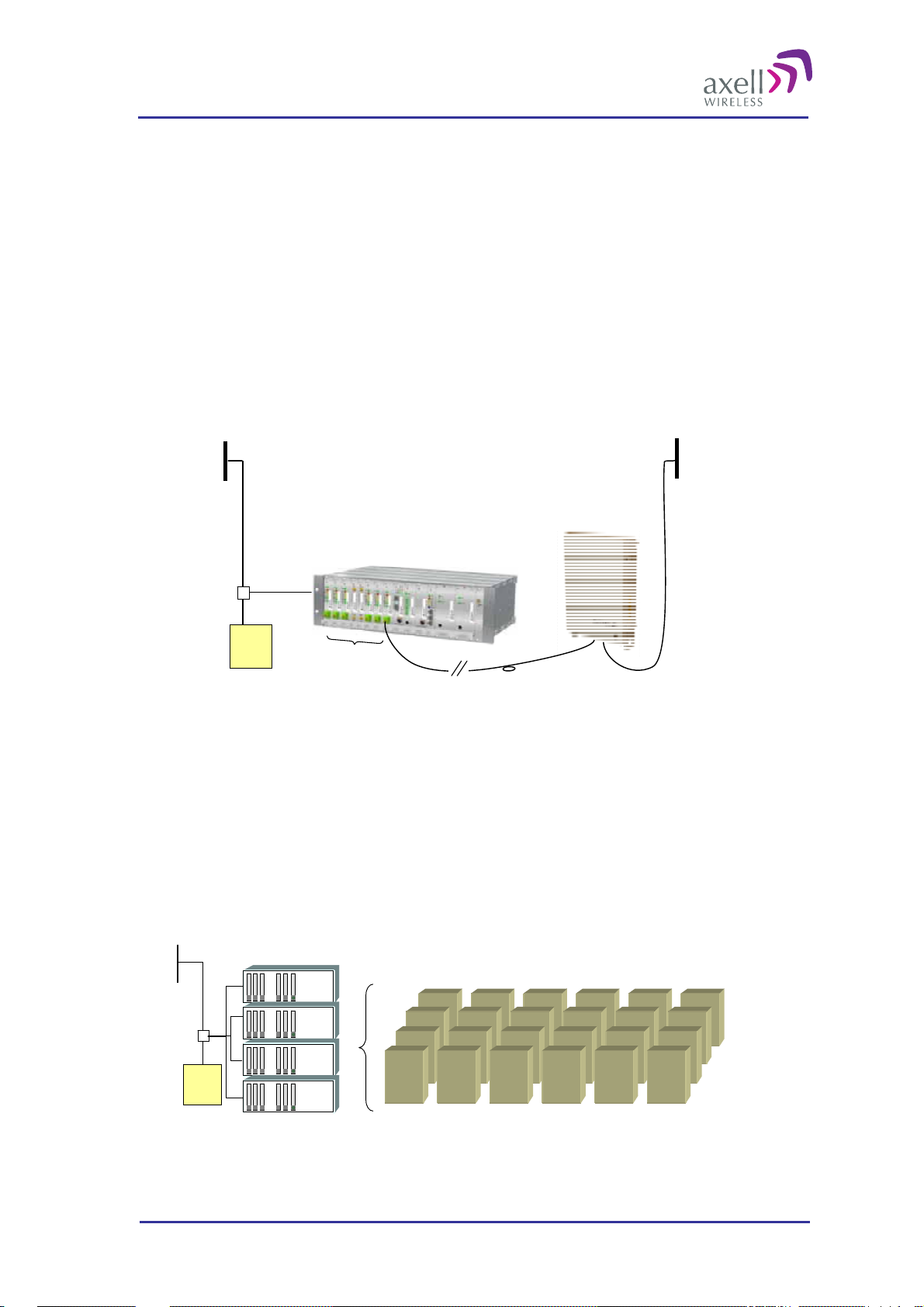
A repeater can work off-air, as the repeater in the example above, or be fe d ove r fibre from an optical master
unit, OMU. The OMU taps the signal directly off a base station via a coupler, converts it to light and transmits
it to a number of repeaters via fibre.
MS MS
BTS
Server antenna
Repeater
1.2 Software Overview
There are three types of software products; dedicat ed firmware for each Axell Wireless repeater or OMU,
Repeater Maintenance Console (RMC) and Axell Element Manager (AEM).
1.2.1 Firmware
The firmware is the software inside the Control Module of the repeater or OMU. It is command line based, with
simple SET and GET commands. A rich variety of commands is available to control and monitor all subsystems
of the repeater from a normal VT100 terminal emulation program, such as HyperTerminal™. This also means
that any standard laptop is able to control a repeater without additional software installed.
The firmware has three main tasks:
Set and configure parameters in the repeater, such as channel numbers, gain, power levels, and different
report configurations
Monitor and measure alarm sources, alarm parameters and repeater utilization
Send reports and alarms to the repeater OMC
Communication with the repeater or OMU can be performed either locally or remotely via a modem or
Ethernet.
© Axell Wireless Ltd A1829300 rev H 10 (86)
Page 12

Optical Master Unit
PRODUCT DESCRIPTION AND USER’S MANUAL
1.2.2 The RMC, Repeater Maintenance Console
RMC is an online software program with an intuitive graphical interface that simplifies control and installation
of the repeater or OMU. The RMC is a graphical shell for the repeater’s Control Module. It reads commands
and attributes from the Control Module and displays them in an intuitive layout. This eliminates the need to
learn commands and attributes for controlling the repeater or OMU.
Login can be made locally via the LMT port or remotely via a modem or via Ethernet. As soon as the RMC is
connected it constantly polls the repeater or OMU for parameters such as power supply levels, in and out levels,
temperature, traffic, etc. If the repeater is a slave type re peater, t he OMU ma nage s the data collection from the
repeater.
The RMC program can be installed from a CD. It is a Windows based application that runs on Windows 2000
and Windows XP.
1.2.3 The AEM, Axell Element Manager
AEM is a complete operations and maintenance centre for Axell Wireless repeater networks.
The AEM takes control of the repeater – or the OMU-Repeater system - once the installation at site is
completed. The repeater gets integrated into the network and will be controlled by the Element Manager.
During integration all repeater parameters and statuses are downloaded into a database. The database is
regularly updated with all incoming alarms and reports, and will hence contain a copy of the repeater
configuration so that current repeater information will be accessible without setting up communication with the
repeaters.
Communication between the AEM and the repeaters are message based. This m eans tha t the operator does not
have to await message delivery, but will be informed when the message is delivered to the repeater
The Axell Element Manager is a Windows™ based application that runs on Windows 2000, Windows 2003
Server and Windows XP.
For more information please refer to the separate AEM User’s Manual.
© Axell Wireless Ltd A1829300 rev H 11 (86)
Page 13
Optical Master Unit
PRODUCT DESCRIPTION AND USER’S MANUAL
2 Product and System Description
2.1 Overview
The Axell Wireless OMU is a product used in combination with fibre fed repeaters. An OMU can be equipped
to be used for frequency ranges from 88MHz to 2 170MHz.
An OMU’s basic function is to translate RF signals to light to be sent over an optical fibre, and vice versa.
In the downlink direction the OMU picks up the signal from the base station via an RF coupler system,
converts it into an analogue optical signal and transfers it over a fibre optical cable to the repeater were it is
translated back to RF and sent out via an antenna. An OMU can also be connected to a repeater. In that
case the signal is tapped from the repeater’s server antenna.
In the uplink direction the OMU receives the signal from the repeater via the fibre optical cable, converts it
to an RF signal and sends it back to the base station.
Server
Antenna
Repeater
OMU
Directional
Coupler
BTS
An OMU-Repeater system consists of one or more Optical Master Units, OMUs and one or several fibre fed
repeaters. An OMU-Repeater system can be expanded to handle up to 24 repeaters, and cover a distance of to
up to 20 km of fibre between the OMU and the most distant repeater.
Each OMU can be equipped with up to 6 fibre optic converters. If more than 6 repeaters are needed in the
network there are two ways of expanding the system: link several OMUs together or use laser systems with
three or four colors.
Up to 4 OMUs can be cascaded and operate up to 24 repeaters as one system. When OMUs are cascaded
only one is equipped with a Control Module. This OMU is called an OMU Master and the other three
OMU slaves. The OMU Master manages the OMU slaves as well as the connected repeaters.
RF
FiberOptic
Converters
Opto Fiber
RF
BTS
RepeatersOMU Units
Four OMUs cascaded in one system
© Axell Wireless Ltd A1829300 rev H 12 (86)
Page 14
Optical Master Unit
PRODUCT DESCRIPTION AND USER’S MANUAL
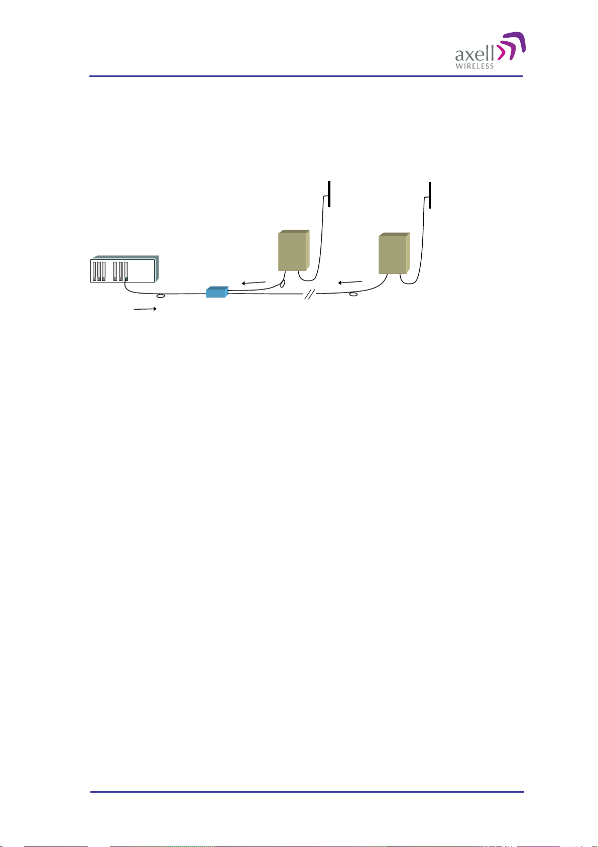
A laser system with two colors can operate one repeater for each fibre optic converter in a OMU-Repeater
system – one color is used for the uplink and one for the downlink. A laser system with three or more
colors can operate two or more repeaters per fibre optic converter. One color is used for the downlink
which is the same for all repeaters, and in the uplink each repeater has its own color.
The connection from one repeater to the next is done via so called add-drop couplers. The difference in
distance between the repeaters and the OMU can be compensated for automatically.
OMU
1310
Add-drop
Coupler
Slave 1
1550
Slave 2
1510
Two repeaters are connected to the same converter in the OMU via the same fibre but the wavelength for the
uplink differs between the units. Slave 1: 1550 ± 3 nm, Slave 2: 1510 ± 3 nm. The downlink signal is the same
for both repeaters.
© Axell Wireless Ltd A1829300 rev H 13 (86)
Page 15

Optical Master Unit
PRODUCT DESCRIPTION AND USER’S MANUAL
2.1.1 Access to the System
Important Generic Information
Axell Wireless repeaters and OMUs can be configured in three different ways as regards communication
and control. They can be “stand-alone units”, “node masters” or “slaves”.
Stand-alone units do not control any other unit or take control from any other unit. All communication
with a stand-alone unit needs to be made directly with the unit – either locally or remotely via a modem or
Ethernet. Most stand-alone units are equipped with Ethernet and/or a modem for this purpose.
Node Masters keep track of the slaves that are connected to it. It is the single point of contact for alarm
reports and for heart beats in the entire system, and communicates with the AEM. All configuration and
control of all units in the network go through this Node Master. Most Node Masters are equipped with
Ethernet and/or a modem for this purpose.
Slaves are linked to a Node Master and contain a slave interface allowing for a Node Master to
communicate with the slave.
An OMU-Repeater system can be designed using repeaters that operate as slaves to the OMU or as stand alone
units regarding communication, configuration, alarms etc. Either all communication is handled by the OMU
that acts as a node master and the repeaters are slaves, or each repeater (and the OMU) handles this
communications and reporting separately.
The most common configuration is the master-slave set up which has several advantages:
All nodes can be reached from any node in the system. An operator can log in from any node in the system
and access all parameters in all nodes, including those in the OMU
Only one modem is needed for remote communication and configuration of the whole system
Since the communication runs on the same fibre as the RF, this arrangement gives a reliable supervision of
the radio link. If communication between the OMU and a repeater is broken, an alarm can be generated
immediately.
Several users at a time can be logged on to the system, for instance one locally via the RS232 interface and one
remotely via modem or Etthernet. Only one user at a time can be logged in remotely.
1
Note! If the network has an OMU from an earlier generation
accessed via a local login to a slave repeater.
, there are some limitations of what can be
2.1.1.1 Local Access
Local access is achieved via an RS232 interface to the LMT port in the repeater or the OMU. This port is
accessible on the front of the OMU and inside the repeater.
2.1.1.2 Remote Access
Remote access is achieved via modem or Ethernet. Different types of modems are supported, for example
GSM, GSM-R, HSDPA/UMTS, TETRA, GPRS and PSTN.
The modem is either placed on the Control Module or as a separate unit. When cascaded OMUs are used, the
modem is placed in the OMU unit that holds the Control Module. Ethernet connection is available on the
Control Module.
1
The earlier versions of the OMU where called HUBs.
© Axell Wireless Ltd A1829300 rev H 14 (86)
Page 16
Optical Master Unit
PRODUCT DESCRIPTION AND USER’S MANUAL
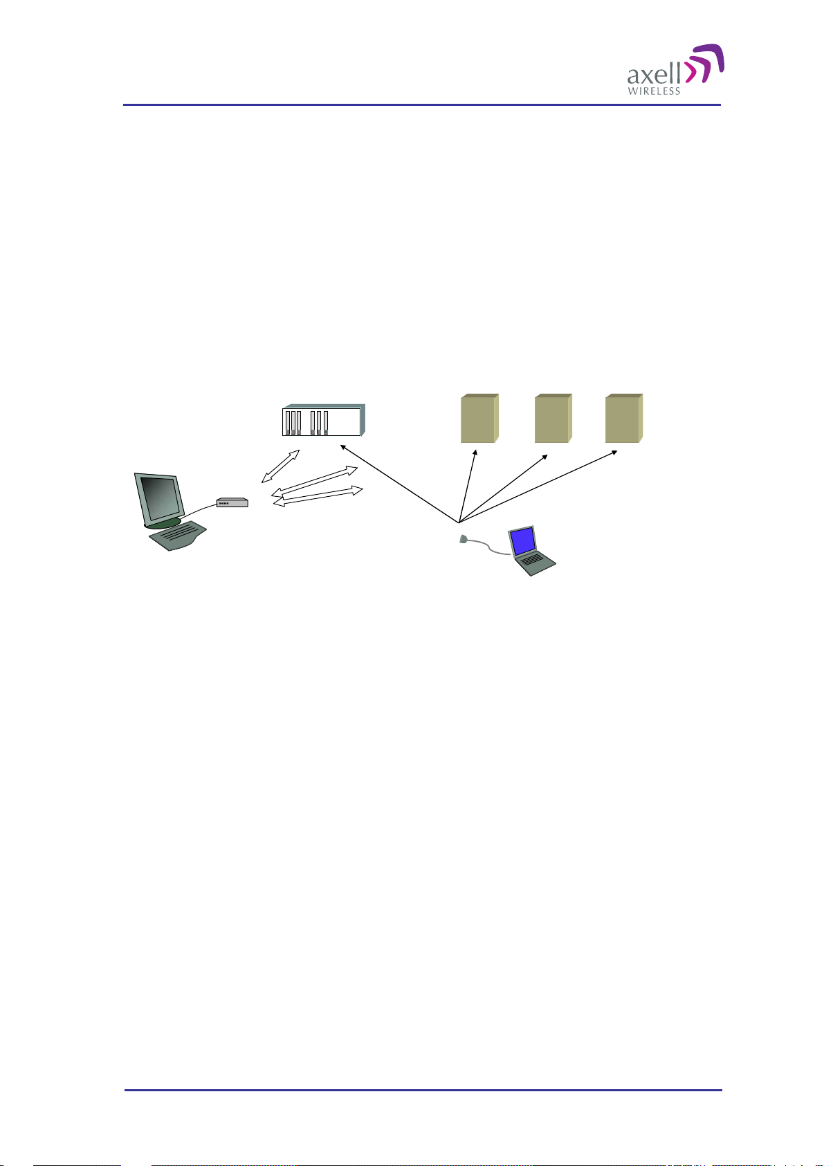
2.1.2 SW for Configuration and Control
There are two SW tools for configuration and control of the Axell Wireless OMU-Repeater system. The RMC,
Repeater Maintenance Consol and the AEM, Axell Wireless Element Manger.
The RMC is an on-line tool that can be used locally or remotely for configuration and monitoring of all
parameters in the system. It is installed on a lap-top computer and holds pre-configured screens for each
repeater type or OMU that shows the parameters live in a user-friendly manner. All parameters can be
accessed and changed on-line. In the RMC there is also a terminal mode that allows for command based
communication.
The AEM is a tool for monitoring and control of a whole network. Data from the network elements are
collected at regular intervals and alarm information are sent to the AEM as they occur. All data are stored
in a data base and can be presented in maps, reports and diagrams.
OMU
GSM, PSTN or TCP/IP
data connection
Modem
AEM or RMC for remote monitoring via modem or Ethernet
Repeaters
RMC for local access
© Axell Wireless Ltd A1829300 rev H 15 (86)
Page 17
Optical Master Unit
PRODUCT DESCRIPTION AND USER’S MANUAL
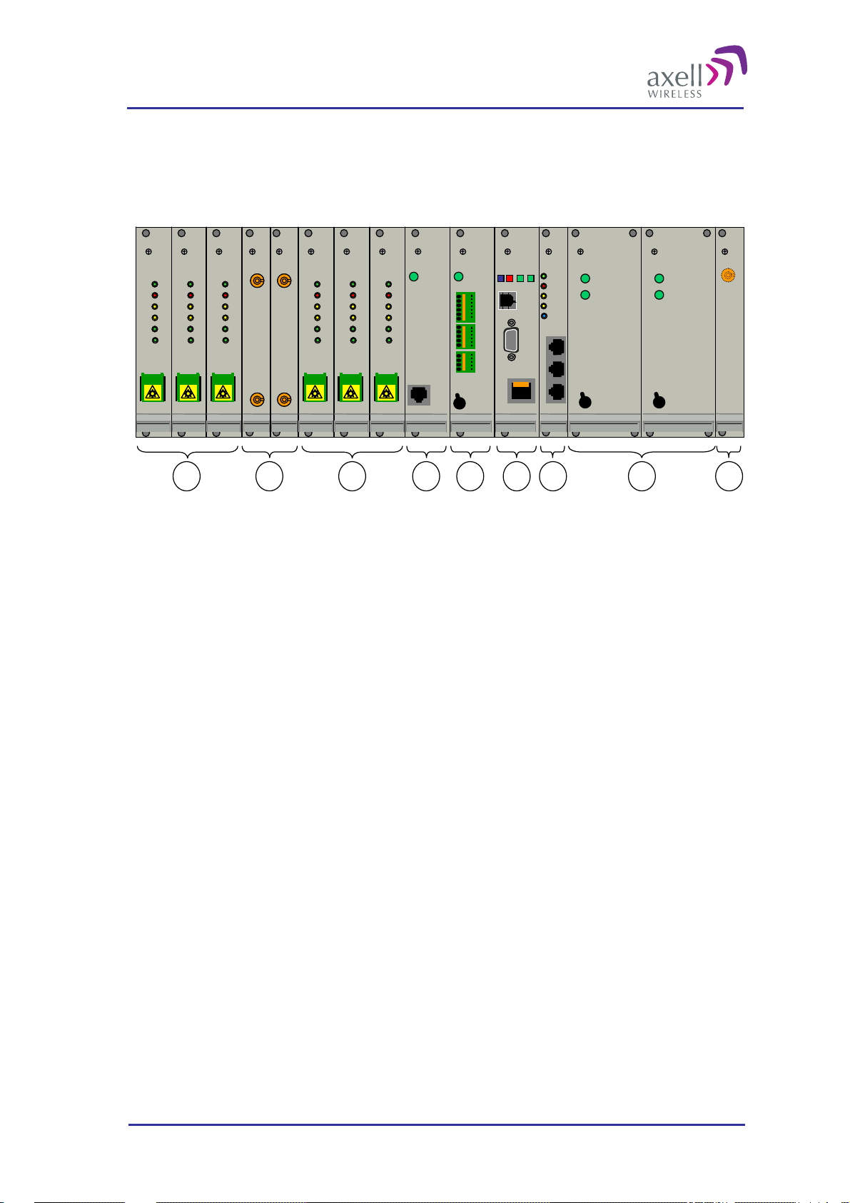
2.2 Building Blocks
The OMU is built in a 19” sub rack.
Modem Status
Modem Power
Status
PWR
Login
PWR
PWR
ERR
ERR
UL
UL
DATA
DATA
DL
DL
DATA
DATA
.
.
.
.
.
.
.
.
.
.
Ethernet
LinkOK
IN
IN
OUT 1
OUT 1
OUT 2
OUT 2
LMT Port
.
.
.
.
.
.
.
.
On
Off
Out OK
In OK
On
Off
Out OK
In OK
On
Off
Modem
ANT
DATA
DATA
DATA
DATA
OPTO
OPTO
OPTO
OPTO
PWR
PWR
ERR
ERR
UL
UL
DL
DL
Rx
Rx
Tx
Tx
SC/APC
SC/APC
DATA
DATA
DATA
DATA
OPTO
OPTO
OPTO
OPTO
PWR
PWR
ERR
ERR
UL
UL
DL
DL
Rx
Rx
Tx
Tx
SC/APC
SC/APC
DATA
DATA
DATA
DATA
OPTO
OPTO
OPTO
OPTO
PWR
PWR
ERR
ERR
UL
UL
DL
DL
Rx
Rx
Tx
Tx
SC/APC
SC/APC
UL in
RF out
DL out
RF in
DATA
DATA
DATA
DATA
OPTO
OPTO
OPTO
OPTO
PWR
PWR
ERR
ERR
UL
UL
DL
DL
Rx
Rx
Tx
Tx
SC/APC
SC/APC
PWR
PWR
ERR
ERR
DATA
DATA
DATA
DATA
OPTO
OPTO
OPTO
OPTO
UL
UL
DL
DL
Rx
Rx
Tx
Tx
SC/APC
SC/APC
DATA
DATA
DATA
DATA
OPTO
OPTO
OPTO
OPTO
PWR
PWR
ERR
ERR
UL
UL
DL
DL
Rx
Rx
Tx
Tx
SC/APC
SC/APC
PWRPWR
Battery
Power
21 1 543 6 7 8
An OMU unit can contain the following modules:
1. Fibre Optic Converters (1 to 6 pcs can be installed)
2. Uplink (UL) Combiner and Downlink (DL) Splitter. These modules are always installed.
3. Modem Unit. This module is optional. This unit is used for modems that are not mounted on the Control
Module
4. External Alarm and Battery Module. This module is optional. This module is only used for Master OMUs
5. Control Module. This module is only used for Master OMUs
6. Rack Communication Board. This module is always installed.
7. Power Supply A and B (B is optional)
8. Modem Antenna Connection. This module is optional. This is used for OMUs with wireless modems
installed that need a separate antenna. This module can also be equipped with two connectors. For details,
see section
2.2.8 Modem Antenna Connection
In the next sections all modules are described in detail.
© Axell Wireless Ltd A1829300 rev H 16 (86)
Page 18
Optical Master Unit
PRODUCT DESCRIPTION AND USER’S MANUAL
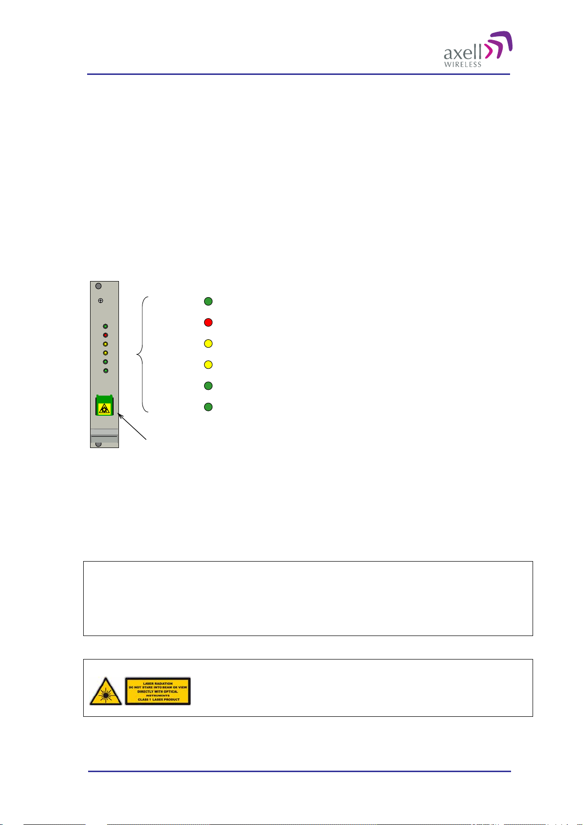
2.2.1 Fibre Optic Converter
The Fibre Optic Converters are placed in slots 1, 2, 3 and 6, 7, 8.
A Fibre Optic Converter translates back and forth between RF and optical signals. The optical signals are
analogue. Each module contains both an optical receiver and a transmitter. The optical signals for downlink and
uplink are combined utilizing WDM technology (Wavelength Division Multiplexing). Hence only one fibre is
necessary for the transmission to and from the repeater.
Each Fibre Optic Converter in the OMU works in parallel with a corresponding unit in the repeater which is
linked via the fiber. A pilot tone can be sent between the Fibre Optic Converters in the OMU and the repeater to
define the loss in the fibre. Based on this information the repeater automatically adjusts the attenuation to
compensate for the fibre loss.
On the Fibre Optic Converter module there are six LED indicators; one for power status, one for error, two for
the data communication and two for the RF signals.
PWR Indicates that the power is on
ERR
DATA
DATA
OPTO
OPTO
PWR
UL
DL
Rx
Tx
ERR Indicates that there is something wrong in the module
UL DATA Ongoing communication in the uplink direct io n
DL DATA Ongoing communication in the downlink direction
OPTO Rx Received signal on fiber channel
OPTO Tx Transmitted signal on fiber channel
SC/APC
Fiber link connection
UL DATA and DL DATA reflect the ongoing data communication
OPTO Rx reflects received RF signal
OPTO Tx reflects transmitted RF signal
The fibre connector is SC/APC. The connector house is SC, the connector type is APC.
Note!
Angled connectors, APC, need to be used throughout the whole link between
the OMU and the repeater. The angle needs to be 8 degrees.
Also the ODF connections need to be APC type.
The fibre must be monomode type.
Caution
Un-terminated optical receptacles may
emit laser radiation. Do not stare into beam
or view with optical instruments.
© Axell Wireless Ltd A1829300 rev H 17 (86)
Page 19
Optical Master Unit
PRODUCT DESCRIPTION AND USER’S MANUAL
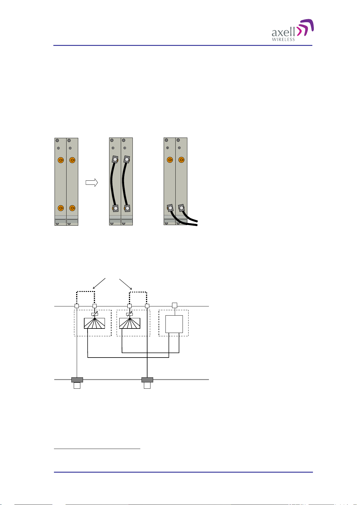
2.2.2 UL Combiner and DL Splitter2
The UL Combiner and DL Splitters are placed in slots 4 and 5.
These two modules contain the combiners and splitters that combine and distribute the RF signals between the
OMU’s RF port and the Fibre Optic Converters. They also contain attenuators that are used for setting the
master signal levels in the downlink and uplink.
Via these modules the RF in/out can be connected on the front of the OMU instead of the back, if needed.
The connectors are QMA type.
The modules can to be configured in two ways as shown in the illustration below.
DL out
UL in
DL out
UL in
DL out
UL in
RF in
RF out
RF in
RF out
RF in
Alternative 1
RF out
Alternative 2
Input to OMU
In Alternative 1 the connectors on each module are linked and the input to the OMU is made via the N-
connectors on the back of the OMU. See also illustration below.
In Alternative 2 the input to the OMU is made via the QMA connectors marked RF in/RF out.
Optional links
Fibre port
DL out
RF in
DL
Splitter
RF out
UL
Combiner
UL in
RF in
RF out
OMU front side
Fibre Optic
Converter
DL
UL
Note! In the illustration above only one Fibre Optic Converter is shown. The other converters are connected in
a corresponding way.
The configuration at delivery is Alternative 1.
OMU back side
2
In some cases, for specific needs, these modules can be designed in alternative ways.
© Axell Wireless Ltd A1829300 rev H 18 (86)
Page 20
Optical Master Unit
PRODUCT DESCRIPTION AND USER’S MANUAL
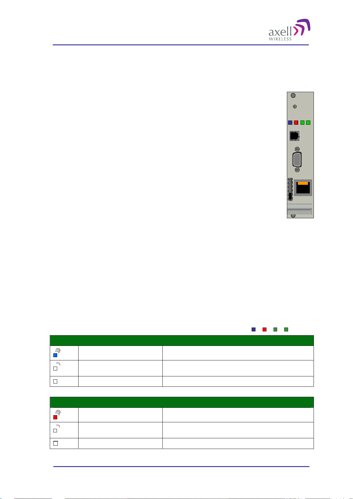
2.2.3 Control Module
The Control Module is placed in slot 9 or 11. Note! If there is a wireless modem mounted in the Control
module it has to be placed in slot 11 to access the modem antenna. See section
Connection.
2.2.8 Modem Antenna
The Control Module manages and controls the OMU and handles alarms. The Control Module
Modem Powe r
keeps track of all modules in the OMU based on their serial numbers. The Control Module
collects data from active modules within the OMU such as Optic Fibre Converters and Rack
Communications Board. The collected data is processed and if an error is detected the Control
Modem Status
Status
Login
Module can send an alarm via a built in modem to an Operations and Maintenance Center
(OMC). All alarms are also stored for later access via the LMT port.
The Control Module can collect the status of 4 external alarm sources connected to the
External Alarm and Battery Module. The summary alarm status of the OMU and the whole
system can be indicated via a relay port. This relay can be used to indicate to external
equipment if the OMU-Repeater system is functioning properly.
LMT Port
.
.
.
.
.
.
.
.
.
.
.
.
.
.
.
.
.
.
The Control Module includes a Real Time Clock (RTC). The RTC keeps track of at what time
alarms and events occur. This RTC has its own backup battery.
The Control Module can be configured in two different modes:
Standalone Mode – the OMU only reports its own status
Ethernet
Node Master – being a node master means that the OMU controls all slaves (repeaters)
connected to it and manages all communication to the AEM for the whole OMU-Repeater
system.
2.2.3.1 Connectors
The Control Module contains a RS232 port used for local access to the repeater, the LMT Port.
The Control Module has an Ethernet connection for remote access placed on the front panel.
If the Control Module is equipped with a wireless modem, a SIM card holder is accessible on the front panel.
Note! The USB connector is not used in this version of the product.
The Control Module has four LEDs which give information regarding the status
of the OMU.
If the OMU is configured for Ethernet communication the two LEDs Modem
Power and Modem Status do not fill any function and can be disregarded.
Blue LED - Login
Red LED - Status
Quick flash Control Module switched on, someone logged in locally and/or remotely
Off (except for a quick flash every 10th
second)
Off (permanent) Control Module switched OFF
Quick flash Control Module switched on, one or more errors/alarms detected
Off (except for a quick flash every 10th
second)
Off (permanent) Control Module switched off
Control Module switched on, no one logged in
Control Module switched on, status OK
Modem Power
Modem Status
Status
Login
© Axell Wireless Ltd A1829300 rev H 19 (86)
Page 21
Optical Master Unit
PRODUCT DESCRIPTION AND USER’S MANUAL
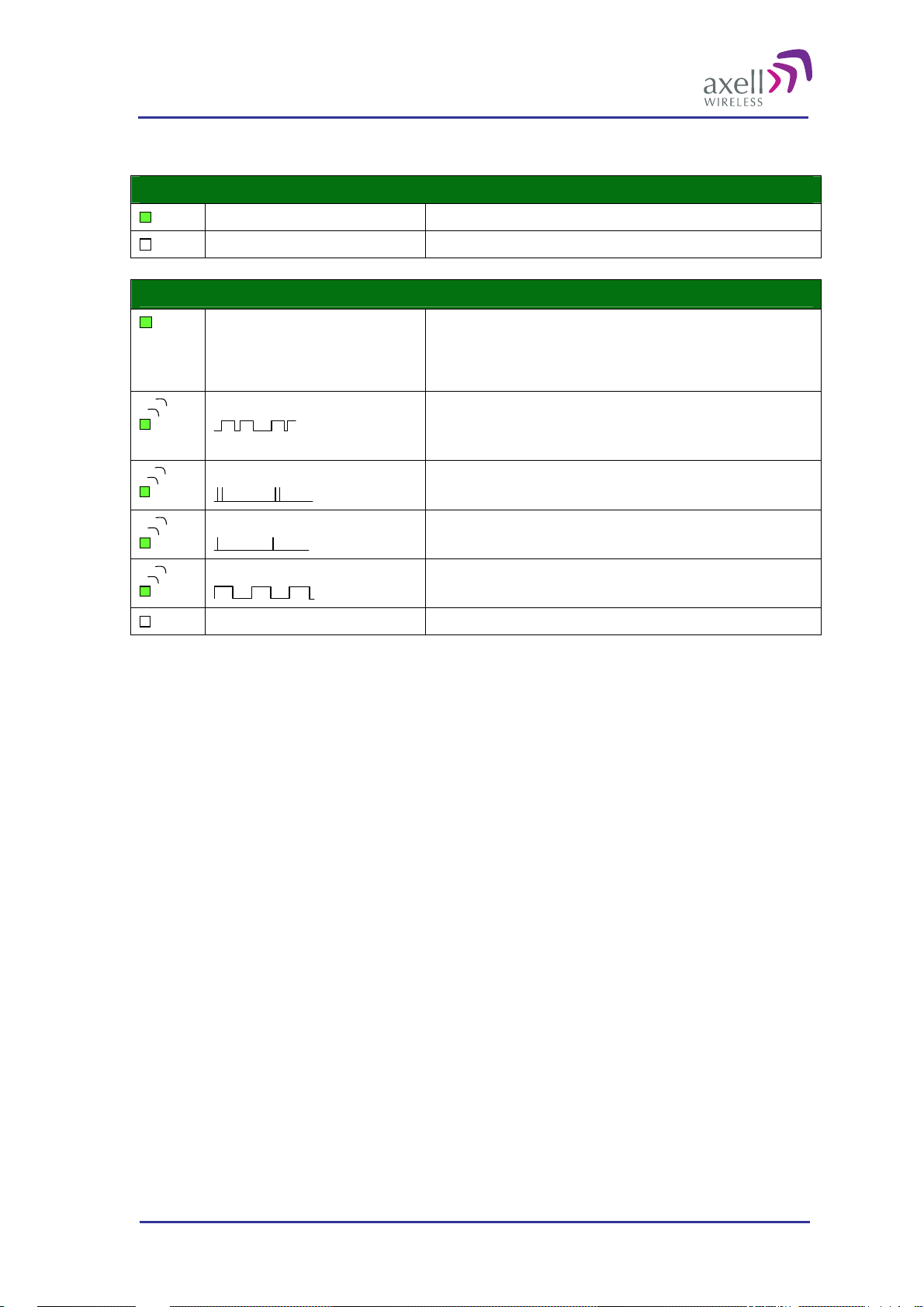
Green LED – Modem Power
Green LED – Modem Status
On Modem Power is on
Off Modem Power is off
On
Flashing
(irregular)
75ms on/75ms off/75ms on/3s off
75ms on/3s off
600ms on/600ms off
Off Modem is off
Depending on type of call:
Voice call: Connected to remote party
Data call: Connected to remote party or exchange of parameters while
setting up or disconnecting a call
Indicates GPSR data transfer. When a GPRS transfer is in progress the LED
goes on within 1 second after data packets were exchanged. Flash duration
in approximately 0.5s.
One or more GPRS contexts activated
Logged to network (monitoring control channels and user interactions). No
call in progress
No SIM card inserted, or no PIN entered, or network search in progress, or
ongoing user authentications, or network login in progress
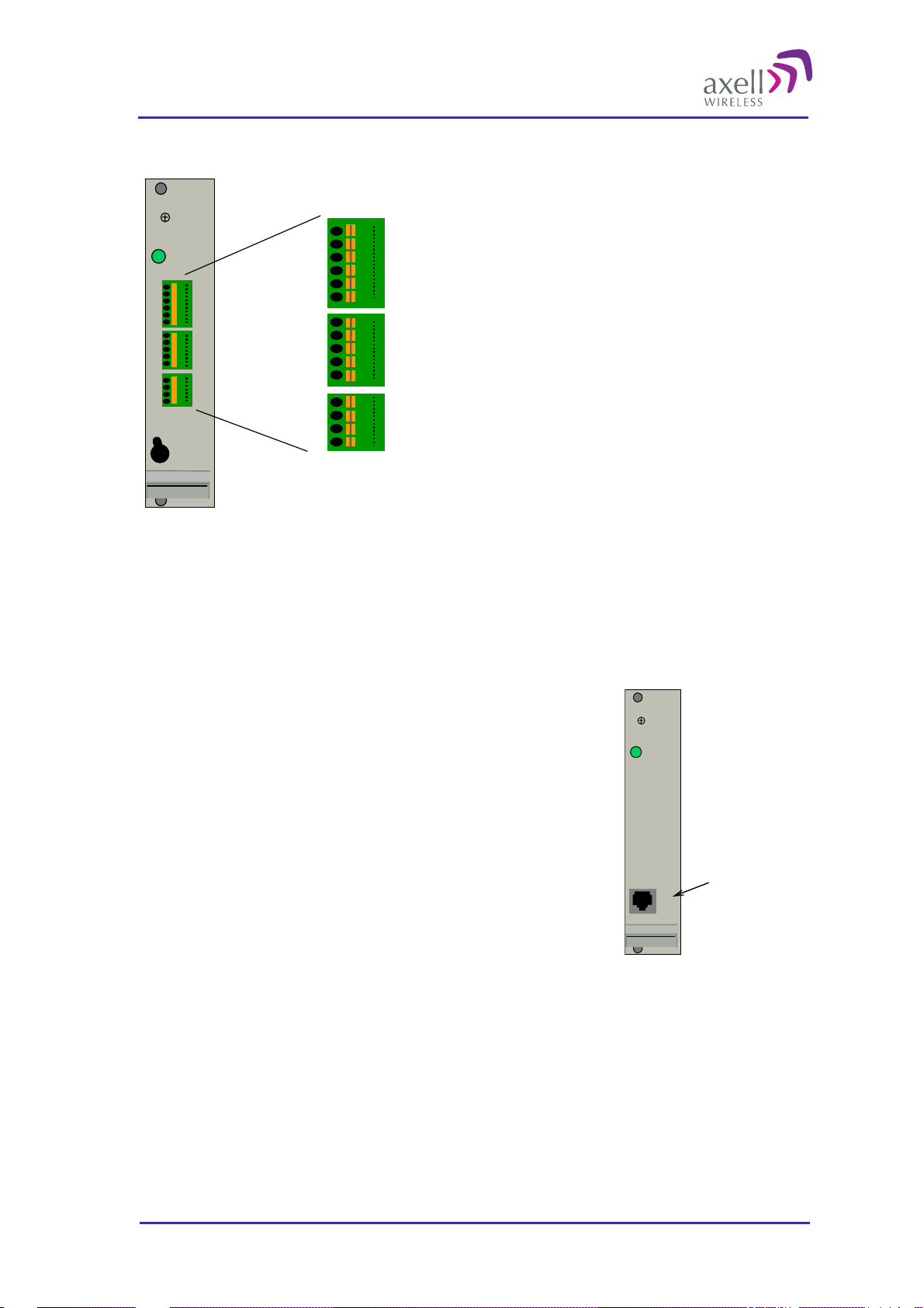
2.2.4 External Alarm and Battery Module
The External Alarm and Battery Module is placed in slot 10.
This module has two functions.
It holds a rechargeable battery pack
It has plinths for external alarms and a sum alarm relay
2.2.4.1 Battery
The rechargeable battery pack will provide the Control Module in the OMU and the modem with enough
capacity to send an alarm in case of an input power failure. This battery can be switched on and off with the
switch on the front of the module.
2.2.4.2 External Alarms
Four external alarm sources can be connected to the External Alarm and Battery Module via the patch panels.
These sources must generate a voltage between 12 and 24VDC. The presen ce or ab sence of this voltage will
trigger the alarm depending on how the alarm thresholds have been configured. The module can also supply
+15V to external alarm sources. The maximum allowed load on this supply is 100mA.
2.2.4.3 Relay
The module contains a relay that can be connected to an external device to indicate an alarm. The relay can be
configured to trigger on any number of internal and external alarms. The maximum current through the relay is
100mA.
© Axell Wireless Ltd A1829300 rev H 20 (86)
Page 22
Optical Master Unit
PRODUCT DESCRIPTION AND USER’S MANUAL
2.2.4.4 Patch Panels
GND
GND
External alarm 1A
External alarm 1B
External alarm 2A
External alarm 2B
Relay Output 1A
Relay Output 1B
+15VDC Output
GND
GND
External alarm 3A
External alarm 3B
External alarm 4A
External alarm 4B
1
2
3
4
5
6
7
8
9
10
11
12
13
14
15
Battery
Power
PWR
On
Off
10
11
12
13
14
15
1
2
3
4
5
6
7
8
9
External Alarm and Battery Module with pin out for external alarms and relay
The external alarm wires are linked to the module via patch panels. These panels can be released from the
module for easier access at installation.
2
The panels can be used for wires of up to 0.5mm
. To connect a wire, press the yellow lever with a pen or other
pointy item, insert the wire and release the lever.
2.2.5 Modem Unit
The Modem Unit is placed in slot 9 or 11. Note! If there is a wireless
modem in the Modem Unit it has to be placed in slot 11 to access the
modem antenna. See also section
The Modem Unit is used for modems that are not placed on the Control
Module. This can be for instance PSTN modems or wireless modems with
a form factor that prevents it from being integrated with the Control
Module.
The access to a PSTN modem is via an RJ11 connector on the font of the
module.
2.2.8 Modem Antenna Connection.
PWR
RJ11 connector
© Axell Wireless Ltd A1829300 rev H 21 (86)
Page 23
Optical Master Unit
PRODUCT DESCRIPTION AND USER’S MANUAL
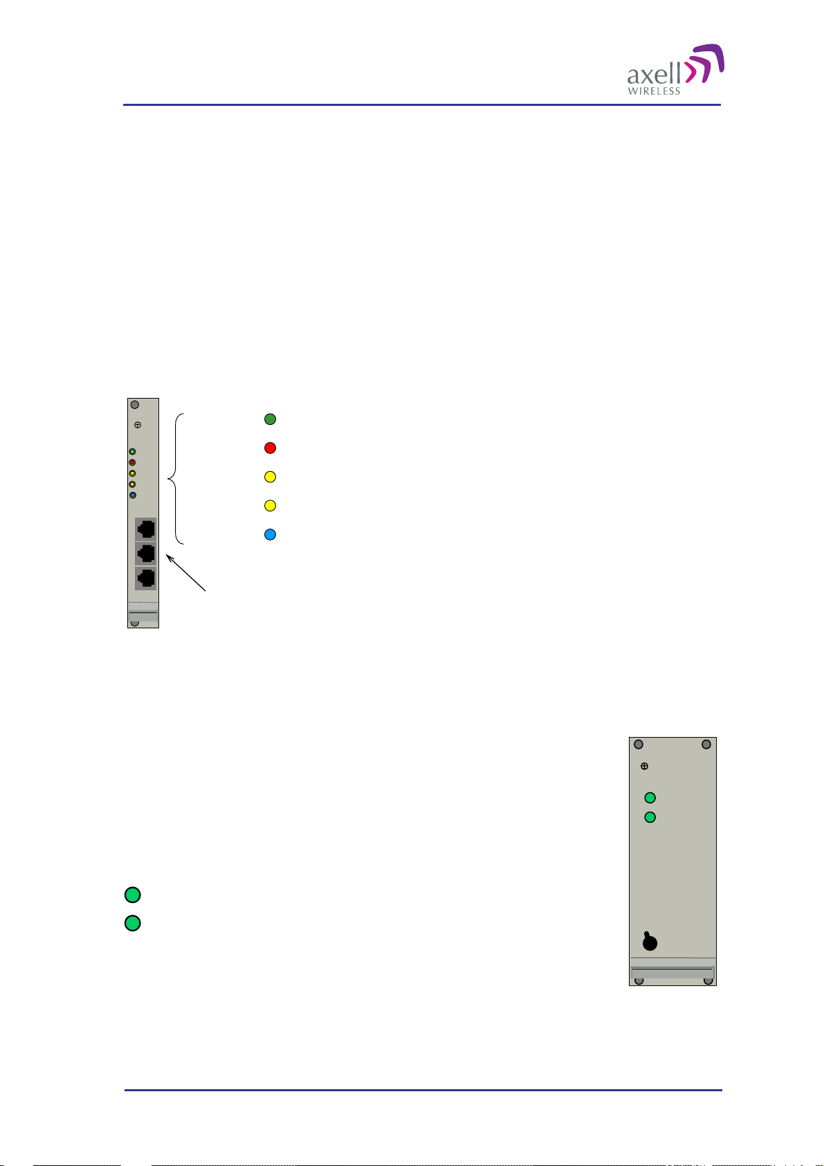
2.2.6 Rack Communication Board
The Rack Communication Board is placed in slot 12.
This module serves as a communications link between the Control Module and the Fiber Optic Converters.
The unit is also used when several OMUs are to be linked together. The cables for cascading OMUs are
provided by Axell Wireless in case these are needed. The connections are RJ45 . How to link the OMUs to one
another is described in section 6 Installation.
There are three LEDs that reflect the status of the communication between the Control Module and the Fiber
Optic Converters.
UL DATA and DL DATA reflect the data communication that is ongoing between this module, the
Control Module and the Fibre Optic Converters.
Link OK is lit when the communication between this unit and the Control Module has been established.
PWR Indicates that the power is on
PWR
PWR
ERR
ERR
UL
UL
DATA
DATA
DL
DL
DATA
DATA
Link OK
Link OK
ERR Indicates that there is something wrong in the module
UL DATA On going communication in the uplink dir ection
DL DATA Ongoing communication in the downlink direction
IN OUT 1
IN OUT 1
Link OK Communication with Control Module established
OUT 2
OUT 2
RJ45 connectors
2.2.7 Power Supply
The Power Supplies are placed in slot 13 and 14.
Each OMU unit is equipped with one or two power supplies. There are power supplies
for 115 - 230VAC 50/60 Hz and 24 - 48VDC.
It is possible to mount two different power supplies (with different voltage) if they are
fed from two different sources.
The power supplies works in parallel and are independent of each other.
Out OK
In OK
Out OK
There are two green LEDs on the Power supplies
“Out OK” indicates that the power levels the unit is delivering
are OK
In OK
“In OK” indicates that the input power to the unit is OK
On
Off
Each Power Supply can be switched off using the switches on the front panel.
Note! Even when the power supplies are switched off the OMU still has live power from the power input on the
back.
© Axell Wireless Ltd A1829300 rev H 22 (86)
Page 24
Optical Master Unit
PRODUCT DESCRIPTION AND USER’S MANUAL
2.2.8 Modem Antenna Connection
If a wireless modem is installed din the OMU, an antenna is needed. Either a separate antenna is connected to
the modem antenna port, or the connection is be made via a coupler connected to the RF input to the OMU. The
latter alternative can only be used if the OMU runs on the same frequency as the wireless modem and is
equipped with a duplex filter.
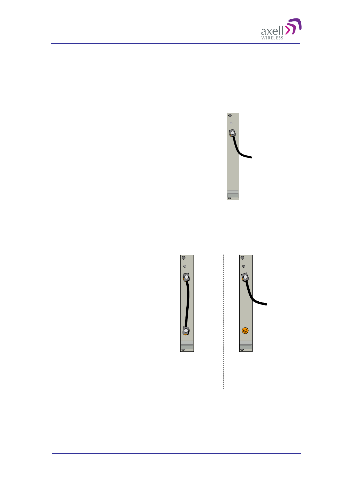
2.2.8.1 OMU without Duplex Filter
OMUs that are not equipped with a duplex filter and use a
wireless modem has a modem antenna port to the rightmost side
of the rack.
An external antenna can be connected to the “Modem Ant” port.
The connector is SMA type.
Modem
ANT
To external
antenna
2.2.8.2 OMU with Duplex Filter
OMUs that are equipped with duplex filters and a wireless modem are of two kinds:
Alternative 1
The OMU and the wireless modem operate on
the same band (for example an OMU for
GSM with a GSM modem).
In this case the OMU will have two ports with
a link between them.
If the link is in place the modem will be
connected to the OMU’s RF in/out via a
coupler. The coupler is either a separate
unit or included in the duplex filter.
If the link is removed an external
antenna can be connected to the top
connector.
Modem
Modem
ANT
ANT
Coupler
Coupler
The wireless
modem is
linked to the
RF in/out via
a coupler
Modem
Modem
ANT
ANT
Coupler
Coupler
An external
antenna is
connected
To external
To external
antenna
antenna
© Axell Wireless Ltd A1829300 rev H 23 (86)
Page 25
Optical Master Unit
PRODUCT DESCRIPTION AND USER’S MANUAL
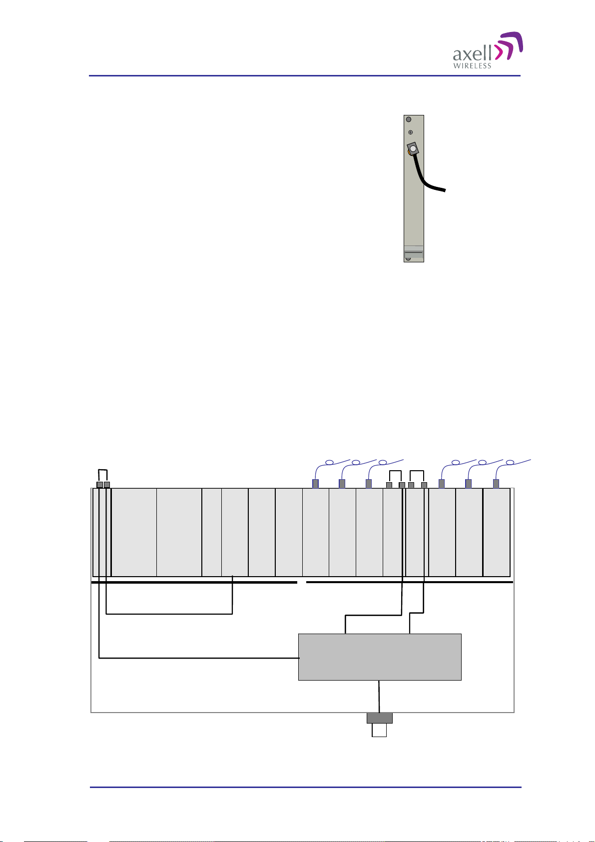
Alternative 2
The OMU and the wireless modem operate on different bands
(for example an OMU for TETRA with a GSM modem)
In this case the OMU will have one port where an external
antenna can be connected.
The connector is SMA type.
Modem
ANT
To external
antenna
2.3 Block Diagram
An OMU can be configured in many different ways. These are two examples.
Example 1
In this example the OMU is fed from the back so the links on the UL Combiner and the DL Splitter units are
mounted.
There is a duplex filter and therefore a combined RF in/out.
The wireless modem, which is placed on the Control Module, is connected to the coupler in the filter via the
Modem Antenna Connection Module.
Digital Backplane
Opto
Module
Opto
Module
Opto
Module
Opto
Module
RF
RF
RF
IN
Power
Module A
Power
Module B
Rack Com Board
Control Module
External Alarm and
Battery Module
OUT
RF
RF
OUT
RF
IN
OUT
DL Splitter
IN
UL Combiner
RF
IN
Opto
Module
RF
OUT
RF
IN
Opto
Module
RF
OUT
RF
IN
Opto
Module
RF
OUT
RF Backplane
Duplex Filter
To coupler for
modem antenna
RF in/out
© Axell Wireless Ltd A1829300 rev H 24 (86)
Page 26
Optical Master Unit
PRODUCT DESCRIPTION AND USER’S MANUAL
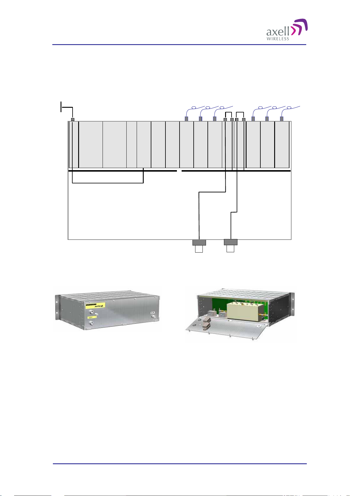
Example 2
In the example below there are separate inputs for Rx and Tx and no duplex filter. An external modem antenna
is connected and linked to the modem on the Control Module.
External Modem A ntenna
Opto
Module
Opto
Module
Opto
Module
Opto
Module
RF
RF
RF
IN
Power
Module A
Power
Module B
Rack Com Board
External Alar m an d
Control Module
Battery Module
OUT
RF
RF
OUT
RF
IN
OUT
DL Splitter
IN
Opto
Module
Opto
Module
Opto
Module
RF
RF
RF
IN
OUT
UL Combiner
RF
RF
OUT
RF
IN
OUT
IN
Digital Backplane
RF in/out
RF Backplane
2.4 Back Panel
An OMU with one RF in/out The inside of the back lid with two plinths for power
connections, a duplex filter and one RF in/out
The back panel of an OMU unit has a layout as illustrated above. The layout can vary depending on the
configuration.
The connections are:
Plinths for power connections are found on the inside of the back panel. There are two plinths. If two
modules with the same power feed are installed these plinths should be interconnected.
Screw for earthing
N-connector for RF input. There is one connector if the Rx/Tx input is combined and two connections if
the Rx and Tx are to be fed separately.
To gain access to the plinths for power connections, duplex filter, optional attenuators and optional coupler the
back panel needs to be opened. It is fastened with 4 screws.
© Axell Wireless Ltd A1829300 rev H 25 (86)
Page 27
Optical Master Unit
PRODUCT DESCRIPTION AND USER’S MANUAL
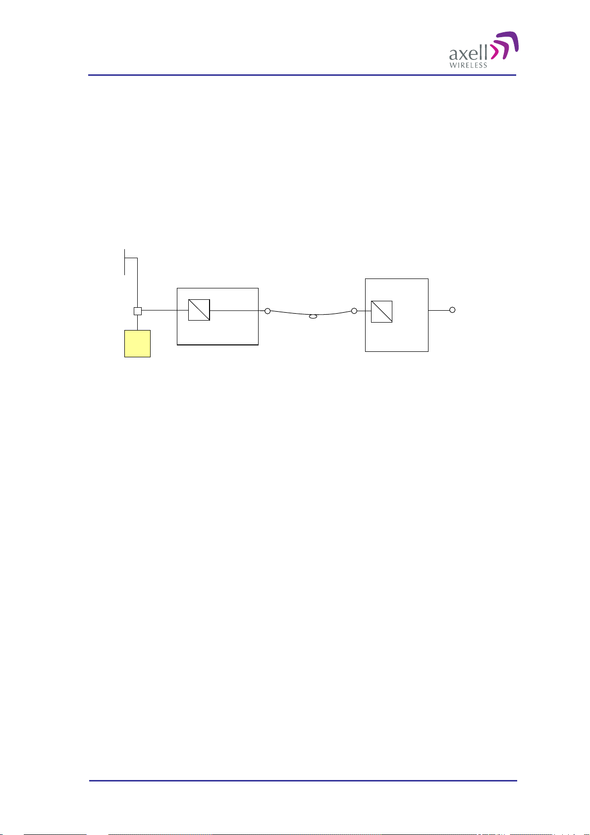
2.5 Radio Signal and Data Communication Paths
In the downlink the radio signal is tapped from a BTS using a coupler installed in series with the BTS’s antenna
cable. The Fibre Optic Converter in the OMU converts the RF signal to an optical signal and sends it to the
repeater over a fibre.
In the uplink the Fibre Optic Converter receives the optical RF signal from the repeater, converts it to electrical
RF signal and sends it to the BTS. The signal is transferred to the antenna cable using a coupler.
The Control Module in the OMU monitors all units in the OMU.
The Control Module also monitors and controls the repeaters (if they are set up as slaves). The data
communication with the repeaters is handled over the same fibre as the RF signals.
Coupler
BTS
OMU
RF
O
RF + data
Optical
In/Out
Optical
In/Out
Repeater
RFORF
O
Server
Antenna
© Axell Wireless Ltd A1829300 rev H 26 (86)
Page 28

Optical Master Unit
PRODUCT DESCRIPTION AND USER’S MANUAL
3 Monitoring and Control
The Optical Master Unit, OMU as well as the whole OMU-Repeater system can be accessed locally on site
through a Local Maintenance Terminal (LMT) port on any of the units in the system, or remotely via modem or
Ethernet.
When an RS232 cable is plugged in to the LMT port or a remote access has been established, there are two
options for communication; terminal mode or RMC mode.
Terminal mode is accessed by using a terminal emulation software, such as HyperTerminal™ or MiniCom
(Linux/Unix) Settings should be AN SI o r VT100 emulation, baud rate 9600, 8 data bits , 1 st op bit , N o
parity and No flow control. A simple command language is used to control the repeater in th is mode.
Repeater Maintenance Console (RMC) mode allows configuration and control of the repeater via a user
friendly Windows software.
Note! All instructions in this chapter assumes that the OMU is controlled using the Repeater Maintenance
Console, RMC.
For terminal mode commands please refer to the documents “Common Commands and Attributes” and “OMU
Commands and Attributes” which contain detailed description of all attributes and commands.
Firmware Documentation Structure
The documents “Common Commands and Attributes” and “OMU Commands and Attributes” together describe
all functionality in the OMU. The Common part contains functionality that is common for all Axell Wireless
repeaters as well as the OMU, and the OMU part contains functionality that is specific for the OMU. For
repeaters there are corresponding documents available.
Help Functions
When being logged in to a unit using the terminal mode the command
HELP
lists all attributes and their modes of operation and displays them in alphabetic order on the screen.
Further help regarding specific commands can be obtained by typing
INF <command>
The INF attribute gives detailed information about a specific attribute.
3.1 Software F eatures - Overview
The firmware in the Control Module controls and monitors all parameters in the unit. If the OMU is configured
as a node master it also handles alarms and heartbeats from slave repeaters connected to it. Statuses and
measured levels can be read online via the RMC. This includes for instance voltage levels, RF-levels and
temperatures.
In the event of a failure, an alarm is logged in the OMU. If the OMU is intergraded in the AEM, the alarm is
also transmitted to the AEM. The OMU can be configured to handle alarms concerning a number of different
parameters. Each alarm can also be individually configured in a number of ways. The OMU stores
approximately 2 000 alarms in a local alarm log. The data stored regarding each alarm is the time at which an
alarm occurred and the alarm information which consists of alarm source, alarm severity, alarm attributes and in
some cases an additional alarm description.
On regular intervals, the OMU can send a heartbeat report to the AEM to confirm that the unit is functioning.
The heartbeat message contains information about the RF-configuration and the alarm sources. It ensures that
the data communication from the OMU to the AEM is working properly. The latest 2 000 heartbeats
(approximately) are stored in a log.
The Control Module contains a battery backed-up real time clock, which will stay active even during a power
failure. The real time clock is used for instance to keep track of when an alarm occurred, when to retransmit an
alarm and at what time of the day to send traffic report to the AEM. If the OMU is controlled by the Axell
© Axell Wireless Ltd A1829300 rev H 27 (86)
Page 29

Optical Master Unit
PRODUCT DESCRIPTION AND USER’S MANUAL
Element Manager, the AEM will automatically time synchronize repeaters, to ensure that the time is always set
correctly in the entire repeater network. Slave repeaters are synchronized from the OMU.
3.2 Network Nodes
Note! The description in this section is based on a master-slave set-up of the system, where the OMU is the
node master and the repeaters are the slaves.
An Axell Wireless OMU-Repeater system consists of an OMU and a number of remote nodes (repeaters)
connected to the OMU unit via fibre. During software setup of the system, all nodes installed in the system are
configured in the Control Module. Hence, the node master contains a list of all the repeaters in the system. Once
a node is added to the system, it is also written to all the nodes installed. This means that all nodes in the
repeater system have information about all other nodes, allowing for a very good overview of the entire repeater
system no matter what node the repeater system login is made from.
3.2.1 Node Identification
All nodes have a unique address within the system. This address is based on the serial number of the node.
When the system is installed to the Axell Element Manager, the node master unit is assigned a unique repeater
ID within the AEM database.
This number is on the form:
XX-YY-ZZZZ
where
XX is the AEM installation number within the network
YY is the region number within the AEM-system
ZZZZ is the site installation number
Within the repeater system, all slave nodes (repeaters) are given a unique ID, based on the AEM assigned ID.
The nodes share the XX-YY- part of the master ID, but the ZZZZ is replaced by the node’s serial number.
Example:
If the node master’s ID is 17-42-4711 and the serial number for a node in the system is 23BJ. The node’s ID
will be 17-42-23BJ.
3.2.2 Node Addressing Modes
When logging in to the OMU-repeater system, it is possible to view information about any of the nodes in the
system, as long as they are added to the node list. All nodes can be addressed in four different ways, all starting
with the @-sign.
Numeric Addressing
Each node in the network gets a unique ID-number in the Node List as they are added to the system. Node 0 is
always the master node.
Addressing is on the format:
@K
K from 0 to N where N is number of nodes
Reading a parameter from node 3 is entered as:
AVITEC AB> @3 GET ATD
14
Serial Number Addressing
A node can be accessed using the serial number of the node.
Example:
© Axell Wireless Ltd A1829300 rev H 28 (86)
Page 30

Optical Master Unit
PRODUCT DESCRIPTION AND USER’S MANUAL
AVITEC AB> @2J34 GET MDL
BSF424-I
AVITEC AB>
Node ID Addressing
A node can also be addressed using the full Node ID.
Example:
AVITEC AB> @01-01-2J34 GET TAG
SITE3_TUNNEL_OPENING
AVITEC AB>
Direct Node Addressing
When many attributes are intended for another node, the user can enter Direct Node Access mode, where the
node the user is logged in redirects all commands to the destination node. This mode is configured by sending
the command:
SET DNA [Node Address]
where any of the node addressing modes can be used as Node Address.
When going into direct node addressing, the command prompt is changed to reflect what node is currently
addressed:
AVITEC AB> SET DNA 2J34
AVITEC AB @2J34>
Refer to attribute DNA in OMU Command and Attribute Summary for further details on direct node addressing.
3.2.3 System Wide Parameters
System Wide Parameters are parameters that when configured should be written to all nodes in the system.
When setting a system wide parameter, the parameter is always set in the node master, which is then
responsible for setting the parameter to all other nodes. If attempting to set a system wide parameter from a
node as access to the node master is not available, setting the parameter will fail.
The following “standard” parameters are treated as system wide parameters (please refer to OMU Command
and Attribute Summary for details):
LMT Local Maintenance Terminal timeout
TIM Setting the time
DAT Setting the date
TPD Setting the time for sending traffic / utilization report to the AEM
UID User ID’s
PWD Passwords
RID Repeater ID
In slave repeaters the OMU is responsible for the communication with the AEM.
3.2.4 Node Access
An operator can login to the OMU-Repeater system from any node in the network and access all parameters in
all nodes, including those in the node master unit. This can be done using a serial cable connected to the node’s
LMT-port or by remote access over a modem or Ethernet.
Select “System Nodes”
© Axell Wireless Ltd A1829300 rev H 29 (86)
Page 31

Optical Master Unit
PRODUCT DESCRIPTION AND USER’S MANUAL
Node detailes: number,
ID, Model
Node name
Node status
Select a node by clicking on
The OMU unit polls the connected repeaters / nodes regularly and keeps control of login requests. If a user at a
repeater site wants to log in to the system, the OMU Control Module is responsible for granting / denying the
login request. If a user forgets to log out from the node when a session is finished, the system will automatically
log the user out after a configurable number of minutes of inactivity.
. The RMC will connect to the selected node.
3.3 Fibre Loss Compensation and Master Volume
The OMU has a master attenuation that can be set in downlink (DL) and uplink (UL) separately. This
attenuation is useful for balancing of the whole system. See section
information about this feature.
Each fibre optic link in the system will induce a loss. This loss will also differ in magnitude from one link to
another since the distances between each repeater and the OMU is different. The Axell Wireless OMU-repeater
system can automatically calculate this loss, compensate for the loss in each link and by that also balance the
system.
4.9 Balance the System for more
This is accomplished by using a pilot tone of a well defined level which is sent from the master node to the
slave and vice versa. The received level of the pilot tone is measured and the loss is calculated. The Fibre Optic
Converter is automatically adjusted to compensate for the loss. The adjustment is made towards a target value
which means that the system will be balanced, i.e. all fibers will appear to have the same loss. The maximum
compensation is 10dB which equals an unbroken fibre distance of 20 km. For each connection in the link (for
instance at the ODF) approximately 0.5 dB of loss will have to be added.
The loss compensation function is activated as the system is set up. Please see section
Repeater System. Each time the system has been changed or fib res ha ve been exc ha ng e d or moved for some
reason, it is recommended to re-activate this function.
Note!
If the OMU is connected to repeaters of an earlier
release that has a fibre optic convert of the type in
the photograph, the Fibre optic loss cannot be
measured with this command.
4.8 Set Up OMU-
© Axell Wireless Ltd A1829300 rev H 30 (86)
Page 32

Optical Master Unit
PRODUCT DESCRIPTION AND USER’S MANUAL
3.4 Alarm System
The OMU monitors a number of parameters to see that the unit works as intended. Furthermore, the Control
Module constantly polls all the nodes for new alarms. If a new alarm is detected, it is stored in the OMU alarm
log. If the OMU is integrated to the Axell Element Manager, the OMU dials up the AEM using the built in
modem and delivers the alarm.
3.4.1 Alarm Sources
Temperature Related Alarms
Alarm Code Description Trigger
Temperature TEM Measures the temperature in the Control Module. Temperature too high or
too low
Radio Board
Temperature
RBT Measures the temperature on the Rack
Communication Board or Fibre Optic Converter
Temperature too high or
too low
Power Related Alarms
Alarm Code Description Trigger
Power Supply 1 PW1 Measures the +28V generated by the re peat er ’s
power supply.
Power Supply 2 PW2 Measures the +15V generated by the re peat er ’s
power supply.
Power Supply 3 PW3 Measures the +6.45 V generated by the repeater’s
power supply
Power Supply 4 PW4 Measures the backed up +6.45 V in rack 1
generated by the repeater’s power supply
Battery Level BAT Measures the power level in the battery Level too high or too
Level too high or too
low
Level too high or too
low
Level too high or too
low
Level too high or too
low
low
Communication Related Alarms
Alarm Code Description Trigger
Communication with
Active Devices
Node
Communication
Status
EEPROM CRC
Check In Active
Devices
© Axell Wireless Ltd A1829300 rev H 31 (86)
COM Detects errors in the communication between
Control Module and Rack Communication
Board/Fibre Optic Converter
NCO Detects error in the communication between the
Control Module and slave repeaters
CRC Controls checksum in Radio Communication
Board and Fibre Optic Converter
Errors in the
communication
Errors in the
communication
Checksum wrong
Page 33

Optical Master Unit
PRODUCT DESCRIPTION AND USER’S MANUAL
Opto Related Alarms
Alarm Code Description Trigger
Received Optical
Level
Transmitted Optical
Level
Synthesizer Pilot
Tone Generator
Input Signal Level
Downlink
RXO Measures the received optical signal level Optical signal level too
low
TXO Measures the transmitted optical signal level No transmission
SZP Measures the pilot tone frequency
ILD Measures the signal level in to the fibre optic
converters in the downlink
Error on pilot tone
Signal level too low
(default setting) or too
high (can be reconfigured
to use an upper threshold)
User Related Alarms
Alarm Code Description Trigger
Valid Login to
repeater
User logged out from
repeater
Changes made by
logged in user
VLI Detects a login to the unit, either locally or via
remote connection.
LGO Detects a logout from the repeater. A logout
CLR Detects all changes made to repeater settings by a
user logged in to the repeater.
A successful login
Changes made by a user
Firmware upgraded FWU Detects when a successful firmware upgrade has
been made
Firmware Upgrade
Failure
FWF Detects failure in the upgrade Upgrade failed
Upgrade successful
User Administration Alarms
Alarm Code Description Trigger
User Added UAD Detects when a user is added to the system User added
User Deleted UDE Detects when a user is deleted from the system User deleted
User Promoted UPM Detects when a user gets escalated user privileges User promoted
User Demoted UDM Detects when a user gets downgraded user
privileges
User Password UPW Detects when a password is changed Changed password
User demoted
External Alarms
Alarm Code Description Trigger
External Alarm 1-4 EX1-4 Monitors any alarm source connected to the
external interface.
Error from alarm source
© Axell Wireless Ltd A1829300 rev H 32 (86)
Page 34

Optical Master Unit
PRODUCT DESCRIPTION AND USER’S MANUAL
Relay Output for Sum Alarm
The External Alarm and Battery Module contains a relay output. The relay can be used to indicate the summary
status of the OMU. Each alarm source can be configured to affect the relay or not.
3.4.2 Alarms and End of Alarms
When the Control Module detects a failure, an alarm is transmitted to the Axell Element Manager, informing
the operator about the error condition. When the alarm has ceased, an end of alarm is sent to the AEM, stating
that the alarm source is now OK.
Each “alarm” and “end of alarm” updates the AEM database with the latest status of the alarm source, ensuring
that the AEM operator always has the correct repeater status in the system.
To generate an alarm a number of consecutive measurements must first show an error state. This can be
configured for each alarm source separately.
To generate an end of alarm only one OK measurement is needed.
Alarm level
Alarm is sent after three
seconds above threshold
End of alarm is sent as
soon as status is OK
Alarm threshold
Time
If an alarm should constantly toggle between OK and ERROR the communications interface might be blocked.
To prevent this there is a parameter called Minimum Alarm Repetition Cycle. This parameter defines how
many minutes must elapse before a new alarm can be transmitted from the same alarm source.
Alarm level
Initial alarm End of Alarm
Three minutes have elapsed and a
new alarm is transmitted
Alarm Threshold
Minimum alarm
repetition
Time
This illustration shows an alarm source with an upper threshold, and a fluctuating level around the alarm
threshold. The initial alarm will be sent as indicated. The next alarm will be transmitted after three minutes,
when the minimum alarm repetition period has elapsed.
© Axell Wireless Ltd A1829300 rev H 33 (86)
Page 35

Optical Master Unit
PRODUCT DESCRIPTION AND USER’S MANUAL
Set Minimum Alarm Repetition Cycle
Select
“Configuration “ and
“Reports”
3.4.3 Alarm Retransmissions and Acknowledgements
As soon as the OMU detects an alarm or an end of alarm, a connection to the Axell Element Manager is
established and the alarm event is reported.
The 2 000 latest alarms and end of alarms are stored in the OMU’s local alarm log. In case an alarm is not
acknowledged the alarm will be retransmitted to the AEM after a configurable number of minutes. Allowed
values are 0 to 999. Default retransmit interval is 10 minutes.
The retransmission will be repeated a configurable number of times. This variable can be set from 0 to 99.
Default number of retries is three
Set Number of Retransmissions and Repetition Cycle for Non-acknowledged
Alarms
Select
“Configuration “ and
“Reports”
3.4.3.1 Alarm Acknowledgement using the RMC
Each alarm can be manually acknowledged using the Repeater Maintenance Console. However, if the OMU is
controlled by the Axell Element Manager, a manual acknowledgement of the alarm means that the AEM will
not be aware of the change in the repeater status.
3.4.3.2 Alarm Acknowledgement using the Axell Element Manager
If the OMU is integrated to and controlled by the Axell Element Manager, an alarm is considered
acknowledged when the alarm has been delivered to the AEM. Once delivered to the AEM, the
acknowledgement of the event is taken care of at the site of the AEM, why no dial-back needs to be performed
to acknowledge the alarms.
3.4.3.3 Alarm Acknowledgement using SMS
Note! SMS functionality is not implemented in this SW release.
If the OMU is configured to send alarms using SMS, alarm acknowledgement can be made in two different
ways.
© Axell Wireless Ltd A1829300 rev H 34 (86)
Page 36

Optical Master Unit
PRODUCT DESCRIPTION AND USER’S MANUAL
the alarm is acknowledged as soon as the alarm SMS is successfully received by the Short Message
Service Centre
or
the alarm is acknowledged by sending a special alarm acknowledgement SMS back to the repeater from
the alarm destination.
Set Acknowledgement Type for SMS Alarms
Select
“Configuration “ and
“Reports”
Pick one alternative
from the drop-down
menu
All alarms transmitted from the OMU contain a message number. Acknowledgement of an alarm is done by
sending an SMS to the repeater containing this message number.
Note! Only the defined “Primary SMS address” can acknowledge alarms.
The table below displays the format of alarm acknowledgement messages.
Message field Format Description
Repeater ID XX-YY-ZZZZ ID of the repeater that the message is intended for
Message number NNNNN Message number set by originator
Command ACT Action command
Argument ACK Acknowledge action
Argument MMMMM Message number of the alarm message to acknowledge
The message fields are separated with blanks.
For example, sending an SMS to the repeater with the text
01-42-4711 00242 ACT ACK 00023
will acknowledge alarm number 00023 from repeater 01-42-4711.
© Axell Wireless Ltd A1829300 rev H 35 (86)
Page 37

Optical Master Unit
PRODUCT DESCRIPTION AND USER’S MANUAL
3.4.4 Alarm Format
Each alarm transmitted from the OMU contains a number of fields, in detail describing the event that caused the
alarm. The alarm is transmitted as an ASCII text string, each fi el d separat ed by a blank/white space.
Using the Axell Element Manager to control the OMU, the alarm string is delivered to the transceiver for
further processing in the AEM system.
When SMS is used to control the OMU, the string is sent as clear text to the alarm address (main address).
Note! The SMS functionality is not implemented in this SW release.
Message
field
Repeater ID XX-YY-ZZZZ 10 ID of the repeater causing the alarm. When monitoring the
Message # N 1 to
Message type ALARM 5 This text string identifies the message as being an alarm (or
Date DDMMYY 6 Day, month and year when the alarm was detected
Time HHMMSS 6 Hour, minute and second when the alarm was detected
Alarm Name CCC 3 Identifies the alarm type (e.g. PW1, SZU, PDL, etc)
Alarm
Severity
Format # of
Description
char.
repeater using the AEM, this repeater ID is set by the AEM
during the repeater installation phase. Using SMS, this
repeater ID should be modified to uniquely identify the
repeater in the network.
This integer value uniquely identifies this message from the
10
CC 2 Abbreviation for severity of the alarm. This severity varies
repeater and may be from 0 to 2147483648 (231).
end of alarm)
between the different alarm sources.
CR = critical
MA = major
MI = minor
WA = warning
CL = cleared
When an and of alarm is sent, the severity is CL = cleared
Alarm Class CC 2 Abbreviation for kind of alarm
CO = communication alarm
EN = environmental alarm
QS = quality of service alarm
PR = processing alarm
EQ = equipment alarm
Status C 1 This status identifier is 0 if end of alarm and 1 if alarm.
Hardware
Enumeration
Position
Identifier
Additional
text
© Axell Wireless Ltd A1829300 rev H 36 (86)
CCCC 1 to 5 Denotes what hardware module the alarm originates from. If
not used, a '-' (dash) is replied.
CCCCCCCCCC
CC
<Text> 60 This quoted string contains additional alarm information, such
1 to
12
Gives detailed information about certain alarm sources. For
some alarms, such as VLI, LGO and CLR, this may contain
user information. If not used, a '-' (dash) is replied.
as measured levels when the alarm condition was detected.
Page 38

Optical Master Unit
PRODUCT DESCRIPTION AND USER’S MANUAL
3.4.5 Alarm Class
Each alarm belongs to a class.
Class Description
CO communications
QS quality of service
PR software or processing
EQ hardware equipment
EN environment (enclosing or surrounding equipment)
All alarms are configured to a class at delivery but can be changed by the user. The external alarms do not have
a classification at delivery, but can be set by the user.
3.4.6 Alarm Severity
Alarms can be of five different severity levels.
Severity Level Description
Critical
Major
Minor
Warning
Cleared
The severity can be defined for each alarm source in the Alarm Configuration screen in the RMC. It is
recommended not to change the default settings.
A critical error has occurred which affects the functionality of the OMU. This type of
alarm requires immediate action.
A major error has occurred. This type of alarm should be invest i gat e d wi t hin a short
time.
A minor error has occurred. This type of alarm should be i nvest i gated, but is not
urgent.
Something has occurred that does not affect the operation of the OMU but may be
important to notice. For example, someone has logged on to the repeater.
A cleared alarm. This is the end of alarm.
© Axell Wireless Ltd A1829300 rev H 37 (86)
Page 39

Optical Master Unit
PRODUCT DESCRIPTION AND USER’S MANUAL
3.4.7 Alarm Configuration
A number of different parameters can be conf i gu red for how the alarms are transmitted to the repeater OMC.
Each alarm source can also be individually configured in a number of different ways.
Select
“Configuration “ and
“Alarms”
Alarm
Class
Severity
Sum alam
Alarm transmission
to OMC enabled
Requires
acknowledgement
Lower and upper
thresholds
Seconds in error
before an alarm is
triggered
Class – Each alarm can be linked to one of the following classes: Common, Quality, Process, Equipment
or Environment. The class is used when the information is presented in the AEM
Severity – Each alarm can be classified regarding severity - Critical, Major, Minor or Warning
Note! It is recommended not to change the default settings.
Enabl. – If this box is ticked the alarm is transmitted to the repeater OMC (AEM)
Note! This only affects the transmission of the alarm. The alarm is still measured, and corresponding alarm
status is still displayed in the repeater status screen and in the heartbeat reports transmitted to the repeater
OMC.
Ack. – All alarms will by default be transmitted to the repeater OMC (AEM) requiring acknowledgement
(the box is checked). Disabling this checkbox removes this requirement, which means that an alarm will
only be transmitted once, regardless if an acknowledgement is received or not.
Upper and lower thresholds can be set for some of the alarms. Please refer to BSR421 Command and
Attribute Summary for details on the usage of thresholds for each alarm source.
Note! The default settings should normally not be changed.
Time – Defines how many seconds an alarm source should be in ERROR before an alarm is triggered.
© Axell Wireless Ltd A1829300 rev H 38 (86)
Page 40

Optical Master Unit
PRODUCT DESCRIPTION AND USER’S MANUAL
External Alarms
Four external alarm sources can be connected to the External Alarm and Battery Module. These can be for
instance fire alarms or external door sensors.
The alarm sources must generate a voltage between 12 and 24 VDC. The presence or absence of voltage will
trigger the alarm depending on how alarm thresholds have been configured in the controller software. Each
alarm can also be given a unique name.
The external alarms can be set as “active high” or “active low”.
As for all alarm sources a delay can be set that defines how many seconds an alarm should be in error state
before an alarm is generated
To define names and polarity of the external alarms use the lower part of the Alarm Configuration screen.
Set the dip-switches
to configure the
external alarms
Give the alarms
unique names
The external alarms
can be given
individual names of
up to 19 characters.
Click on Edit and
insert the new
names.
New name for
external alarm 1
Sum Alarm
The External Alarm and Battery Module contains a relay output. The relay can be used to indicate a summary
status of the repeater. Each alarm source can be configured to be affecting the relay or not.
Note! The relay status is never affected by the login / logout alarm parameters.
For installation testing purposes, it is possible to test the open / close function of the relay. This test procedur e
closes the relay for 3 seconds, then opens it for 10 seconds, and finally closes it for 3 seconds before going back
to original state.
The relay can be set to close or open to indicate an alarm. This can be changed by changing the polarity.
Click on Relay Test
Relay polarity
© Axell Wireless Ltd A1829300 rev H 39 (86)
Page 41

Optical Master Unit
PRODUCT DESCRIPTION AND USER’S MANUAL
3.4.8 Alarm Monitoring
The alarms can be monitored via the RMC. Each alarm has an indicator on the screen that is either green or red.
See also reference to section
Ensure online
communication with
the OMU
Control Module
related alarms
Power supply related
alarms
3.4.1 Alarm Sources.
Select “HUB Status” for this window
Control Module Related Alarms
EEPROM CRC, CRC Faulty checksum in Rack Communication Board or Fibre Optic Converter. Click
on
as well as all Fibre Optic Converters
Controller Temp, TEM Temperature in Control Module too high or too low
External Alarms, EX1-4 Alarm from external source
for information regarding checksums in all Rack Communication Boards
Power Supply Related Alarms
Power P1-4, PW1-4 +28VDC, +15VDC, +6,45VD and backed up +6,45 VDC too high or too low
Battery, BAT Power level in battery too high or too low
Rack Related Alarms
Communication alarm
Temperature alarm
Com, COM Error in communication between Rack Communication Board and Control
Temperature, RBT Temperature in Rack Communication Board too high or too low
Module
Fibre Optic Converter Related Alarms
Alarms for each
fibre optic
converter
Alarms for combiner
and splitter units
© Axell Wireless Ltd A1829300 rev H 40 (86)
Page 42

Optical Master Unit
PRODUCT DESCRIPTION AND USER’S MANUAL
Com, COM Error in communication between Fibre Optic Converter and Control Module
Received Level, RXO Received optical level too low
Transmitter, TXO No detectable transmitted optical signal
Temperature, RBT Temperature in Fibre Optic Converter too high or too low
Pilot Tone Gen Synth, SZP Pilot tone frequency faulty
Com, COM Error in communication between Combiner or Sp litter and Control Module
Level after attenuator, ILD Signal level in to fibre optic converter too low (or too high)
System Node Alarms
Select “System Nodes” for this window
System node alarms
Node Communication, NCO Error in communication with slave (repeater)
Status Summary status of slave repeater
© Axell Wireless Ltd A1829300 rev H 41 (86)
Page 43

Optical Master Unit
PRODUCT DESCRIPTION AND USER’S MANUAL
3.4.9 Alarm Log
The logged alarms can be viewed in an alarm log.
Monitor Alarm Log via the RMC
Select “Alarm Log”
and “Alarm Log”
Message No
Date/Time
Description
Attribute/Alarm Source
Severity
Class
Alarm acknowledged
Acknowledgement
using RMC
© Axell Wireless Ltd A1829300 rev H 42 (86)
Page 44

Optical Master Unit
PRODUCT DESCRIPTION AND USER’S MANUAL
3.5 OMU Heartbeat
The OMU and connected repeaters can be configured to transmit heartbeat reports to the Axell Element
Manager, AEM with regular intervals. If the AEM does not receive a heartbeat report within expected interval,
an alarm can be generated and displayed to the operator. In this way, the AEM is ensured that the
communication with the OMU works as intended.
Each heartbeat contains a complete status report regarding the sending unit at the time of the report. This
ensures that the AEM always has the correct status information even if some alarm reports should fail to
transmit successfully.
When it is time for the OMU to send a heartbeat report, a connection to the AEM is established, after which
heartbeat reports from all nodes in the repeater system is transmitted. This is the sequence of events.
A connection to the AEM is established
All non-acknowledged alarms in the alarm log are transmitted
The OMU polls the heartbeat from all the nodes and transmits them to the AEM
Heartbeat is transmitted for the OMU unit
The OMU disconnects from the AEM
The heartbeat interval can be set from 1 to 1440 minutes. Setting the heartbeat to 0 disables the transmission of
heartbeats.
Select
“Configuration “ and
“Reports”
3.5.1 Heartbeat Tasks
With the heartbeat reports, a number of tasks are carried out.
3.5.1.1 Ensuring OMU to AEM Communications path
By configuring the OMU to regularly establish a connection to the AEM, the functionality of the data
communications path between the OMU and the AEM is verified. This ensures that for instance the alarms will
be transmitted properly.
If an expected heartbeat is not received by the AEM, an alarm is generated to the AEM operator. Reasons for a
heartbeat message failing to be delivered can be:
No power – the OMU site might experience a power failure, and the battery backing up the Control
Module and modem is empty
Failing modem communication – The modem might be broken, the modem antenna compromised or the
service down in the modem’s frequency area
Broken link to BTS - If the link to the BTS has been tampered with, the OMU might not get adequate
signal to establish a connection to the AEM
Failing BTS – If the feeding BTS for some reason goes down, the OMU will loose its network connection,
and hence fail to establish a connection to the Axell Element Manager.
© Axell Wireless Ltd A1829300 rev H 43 (86)
Page 45

Optical Master Unit
PRODUCT DESCRIPTION AND USER’S MANUAL
3.5.1.2 AEM Database Synchronization
The Axell Element Manager stores all OMU parameters in a database. This database is populated during the
OMU integration into the AEM when the AEM downloads all the OMU parameters. If the AEM operator wants
to monitor the configuration of the OMU, the parameters can be read from the database without having to
connect to the repeater.
In case of an alarm, the AEM updates the database with the status of the alarm source. In case the OMU fails to
deliver the alarm to the AEM there will be a discrepancy between the OMU configuration and the configuration
in the database. For this reason, each heartbeat report contains all the relevant parameters and status of all the
alarm sources in the OMU. This means that each heartbeat report will update the AEM with all status and RF
parameters.
Note! Once the OMU is integrated to the Axell Element Manager, it is recommended that all reconfigurations
are made from the AEM.
Note! If a user logs in to the OMU making changes, as soon as the user logs out, an alarm will be transmitted to
the AEM informing the operator that a change has been made. When this alarm is received, the operator can
initiate OMU synchronization where all OMU parameters will be updated.
3.5.1.3 Time Synchronization
Each heartbeat message transmitted to the AEM contains a time stamp of the local time inside the OMU. Upon
reception in the AEM, the time stamp is compared to the Axell Element Manager time. If the difference
between the OMU and AEM time is too big, time synchronization is initiated by the AEM, adjusting the time in
the OMU. In this way it is ensured that an OMU integrated to the Axell Element Manager always contains the
correct time information.
Note! If the time is adjusted by a user logged in to the OMU, once the user logs out, a heartbeat is sent to the
AEM to ensure that the time is correctly synchronized.
3.5.2 Heartbeat Format
The heartbeat report is transmitted as an ASCII text string, with a number of fields representing the status
parameters, each field separated by a blank/white space.
Field Format Description # of chars
Repeater ID XX-YY-ZZZZ 10
Message no NNNNNNNNN 9
State STATE 5
Date DDMMYY 6
Time HHMMSS 6
BAT N Status of Battery Charge 1
COM-RCB NNNN Status of communication with Rack Communication Boards 4
COM-FO Rack 1 NNNNNN Status of communication with FiberOptic Modules in Rack 1 6
COM-FO Rack 2 NNNNNN Status of communication with FiberOptic Modules in Rack 2 6
COM-FO Rack 3 NNNNNN Status of communication with FiberOptic Modules in Rack 3 6
COM-FO Rack 4 NNNNNN Status of communication with FiberOptic Modules in Rack 4 6
CRC KLMNXYZ Status of CRC in the different modules.
These values are Hex Coded, and should be used in conjunction with
COM status for actual device.
7
© Axell Wireless Ltd A1829300 rev H 44 (86)
Page 46

Optical Master Unit
PRODUCT DESCRIPTION AND USER’S MANUAL
For example, the Byte 1 status is sent as Hex ‘8’, which is extracted to
1000.
Byte 1
Bit 1 Bit 2 Bit 3 Bit 4
CRC for
RCB in
Rack 1
Byte 2
Bit 1 Bit 2 Bit 3 Bit 4
CRC for
Rack 1
Slot 1
Byte 3
Bit 1 Bit 2 Bit 3 Bit 4
CRC for
Rack 1
Slot 5
Byte 4
Bit 1 Bit 2 Bit 3 Bit 4
CRC for
Rack 2
Slot 3
Byte 5
Bit 1 Bit 2 Bit 3 Bit 4
CRC for
Rack 3
Slot 1
CRC for
RCB in
Rack 2
CRC for
Rack 1
Slot 2
CRC for
Rack 1
Slot 6
CRC for
Rack 2
Slot 4
CRC for
Rack 3
Slot 2
CRC for
RCB in
Rack 3
CRC for
Rack 1
Slot 3
CRC for
Rack 2
Slot 1
CRC for
Rack 2
Slot 5
CRC for
Rack 3
Slot 3
CRC for
RCB in
Rack 4
CRC for
Rack 1
Slot 4
CRC for
Rack 2
Slot 2
CRC for
Rack 2
Slot 6
CRC for
Rack 3
Slot 4
NCO
Byte 6
Bit 1 Bit 2 Bit 3 Bit 4
CRC for
Rack 3
Slot 5
Byte 7
Bit 1 Bit 2 Bit 3 Bit 4
CRC for
Rack 4
Slot 3
KLMNXY Status of communication with the node slaves.
These values are Hex Coded, and should be used in conjunction with
NON attribute to know how many nodes are installed.
For example, the Byte 1 status is sent as Hex ‘8’, which is extracted to
1000.
Byte 1
Bit 1 Bit 2 Bit 3 Bit 4
NCO for
node 1
Byte 2
Bit 1 Bit 2 Bit 3 Bit 4
CRC for
Rack 3
Slot 6
CRC for
Rack 4
Slot 4
NCO for
node 2
CRC for
Rack 4
Slot 1
CRC for
Rack 4
Slot 5
NCO for
node 3
CRC for
Rack 4
Slot 2
CRC for
Rack 4
Slot 6
NCO for
node 4
© Axell Wireless Ltd A1829300 rev H 45 (86)
Page 47

Optical Master Unit
PRODUCT DESCRIPTION AND USER’S MANUAL
NCO for
node 5
Byte 3
Bit 1 Bit 2 Bit 3 Bit 4
NCO for
node 9
Byte 4
Bit 1 Bit 2 Bit 3 Bit 4
NCO for
node 13
Byte 5
Bit 1 Bit 2 Bit 3 Bit 4
NCO for
node 17
Byte 6
Bit 1 Bit 2 Bit 3 Bit 4
NCO for
node 21
PW1 NNNN Status of 28 V Power Supply distribution 4
NCO for
node 6
NCO for
node 10
NCO for
node 14
NCO for
node 18
NCO for
node 22
NCO for
node 7
NCO for
node 11
NCO for
node 15
NCO for
node 19
NCO for
node 23
NCO for
node 8
NCO for
node 12
NCO for
node 16
NCO for
node 20
NCO for
node 24
PW2 NNNN Status of 15 V Power Supply distribution 4
PW3 NNNN Status of 6.45 V Power Supply distribution 4
PW4 N Status of 6.45 V Backup Power Supply distribution 1
RBT
KLMNXYZ Status of board temperatures in the different modules.
These values are Hex Coded, and should be used in conjunction with
COM status for actual device.
For example, the Byte 1 status is sent as Hex ‘8’, which is extracted to
1000.
Byte 1
Bit 1 Bit 2 Bit 3 Bit 4
RBT for
RCB in
Rack 1
Byte 2
Bit 1 Bit 2 Bit 3 Bit 4
RBT for
Rack 1
Slot 1
Byte 3
Bit 1 Bit 2 Bit 3 Bit 4
CRC for
RCB in
Rack 2
RBT for
Rack 1
Slot 2
RBT for
RCB in
Rack 3
RBT for
Rack 1
Slot 3
RBT for
RCB in
Rack 4
RBT for
Rack 1
Slot 4
7
RBT for
Rack 1
Slot 5
Byte 4
Bit 1 Bit 2 Bit 3 Bit 4
RBT for
Rack 2
RBT for
Rack 1
Slot 6
RBT for
Rack 2
RBT for
Rack 2
Slot 1
RBT for
Rack 2
RBT for
Rack 2
Slot 2
RBT for
Rack 2
© Axell Wireless Ltd A1829300 rev H 46 (86)
Page 48

Optical Master Unit
PRODUCT DESCRIPTION AND USER’S MANUAL
Slot 3 Slot 4 Slot 5 Slot 6
Byte 5
Bit 1 Bit 2 Bit 3 Bit 4
RXO
RBT for
Rack 3
Slot 1
Byte 6
Bit 1 Bit 2 Bit 3 Bit 4
RBT for
Rack 3
Slot 5
Byte 7
Bit 1 Bit 2 Bit 3 Bit 4
RBT for
Rack 4
Slot 3
KLMNXY Status of received optical level.
These values are Hex Coded, and should be used in conjunction with
COM status for actual device.
For example, the Byte 1 status is sent as Hex ‘8’, which is extracted to
1000.
Byte 1
Bit 1 Bit 2 Bit 3 Bit 4
RXO for
Rack 1
Slot 1
RBT for
Rack 3
Slot 2
RBT for
Rack 3
Slot 6
RBT for
Rack 4
Slot 4
RXO for
Rack 1
Slot 2
RBT for
Rack 3
Slot 3
RBT for
Rack 4
Slot 1
RBT for
Rack 4
Slot 5
RXO for
Rack 1
Slot 3
RBT for
Rack 3
Slot 4
CRC for
Rack 4
Slot 2
RBT for
Rack 4
Slot 6
6
RXO for
Rack 1
Slot 4
Byte 2
Bit 1 Bit 2 Bit 3 Bit 4
RXO for
Rack 1
Slot 5
Byte 3
Bit 1 Bit 2 Bit 3 Bit 4
RXO for
Rack 2
Slot 3
Byte 4
Bit 1 Bit 2 Bit 3 Bit 4
RXO for
Rack 3
Slot 1
Byte 5
Bit 1 Bit 2 Bit 3 Bit 4
RXO for
Rack 3
Slot 5
Byte 6
RXO for
Rack 1
Slot 6
RXO for
Rack 2
Slot 4
RXO for
Rack 3
Slot 2
RXO for
Rack 3
Slot 6
RXO for
Rack 2
Slot 1
RXO for
Rack 2
Slot 5
RXO for
Rack 3
Slot 3
RXO for
Rack 4
Slot 1
RXO for
Rack 2
Slot 2
RXO for
Rack 2
Slot 6
RXO for
Rack 3
Slot 4
RXO for
Rack 4
Slot 2
Bit 1 Bit 2 Bit 3 Bit 4
© Axell Wireless Ltd A1829300 rev H 47 (86)
Page 49

Optical Master Unit
PRODUCT DESCRIPTION AND USER’S MANUAL
SZP
RXO for
Rack 4
Slot 3
KLMNXY Synthesizer in Pilot Tone Generator.
These values are Hex Coded, and should be used in conjunction with
COM status for actual device.
For example, the Byte 1 status is sent as Hex ‘8’, which is extracted to
1000.
Byte 1
Bit 1 Bit 2 Bit 3 Bit 4
SZP for
Rack 1
Slot 1
Byte 2
Bit 1 Bit 2 Bit 3 Bit 4
SZP for
Rack 1
Slot 5
Byte 3
Bit 1 Bit 2 Bit 3 Bit 4
SZP for
Rack 2
Slot 3
RXO for
Rack 4
Slot 4
SZP for
Rack 1
Slot 2
SZP for
Rack 1
Slot 6
SZP for
Rack 2
Slot 4
RXO for
Rack 4
Slot 5
SZP for
Rack 1
Slot 3
SZP for
Rack 2
Slot 1
SZP for
Rack 2
Slot 5
RXO for
Rack 4
Slot 6
6
SZP for
Rack 1
Slot 4
SZP for
Rack 2
Slot 2
SZP for
Rack 2
Slot 6
Byte 4
Bit 1 Bit 2 Bit 3 Bit 4
SZP for
Rack 3
Slot 1
Byte 5
Bit 1 Bit 2 Bit 3 Bit 4
SZP for
Rack 3
Slot 5
Byte 6
Bit 1 Bit 2 Bit 3 Bit 4
SZP for
Rack 4
Slot 3
TEM N Status of Controller Temperature 1
TXO
KLMNXY Status of Optical Transmitter.
These values are Hex Coded, and should be used in conjunction with
COM status for actual device.
For example, the Byte 1 status is sent as Hex ‘8’, which is extracted to
1000.
Byte 1
SZP for
Rack 3
Slot 2
SZP for
Rack 3
Slot 6
SZP for
Rack 4
Slot 4
SZP for
Rack 3
Slot 3
SZP for
Rack 4
Slot 1
SZP for
Rack 4
Slot 5
SZP for
Rack 3
Slot 4
SZP for
Rack 4
Slot 2
SZP for
Rack 4
Slot 6
6
Bit 1 Bit 2 Bit 3 Bit 4
TXO for
Rack 1
Slot 1
TXO for
Rack 1
Slot 2
TXO for
Rack 1
Slot 3
TXO for
Rack 1
Slot 4
© Axell Wireless Ltd A1829300 rev H 48 (86)
Page 50

Optical Master Unit
PRODUCT DESCRIPTION AND USER’S MANUAL
Byte 2
Bit 1 Bit 2 Bit 3 Bit 4
TXO for
Rack 1
Slot 5
Byte 3
Bit 1 Bit 2 Bit 3 Bit 4
TXO for
Rack 2
Slot 3
Byte 4
Bit 1 Bit 2 Bit 3 Bit 4
TXO for
Rack 3
Slot 1
Byte 5
Bit 1 Bit 2 Bit 3 Bit 4
TXO for
Rack 3
Slot 5
Byte 6
Bit 1 Bit 2 Bit 3 Bit 4
TXO for
Rack 4
Slot 3
EX1/EX2/EX3/EX4 NNNN Status of external alarm inputs 4
TXO for
Rack 1
Slot 6
TXO for
Rack 2
Slot 4
TXO for
Rack 3
Slot 2
TXO for
Rack 3
Slot 6
TXO for
Rack 4
Slot 4
TXO for
Rack 2
Slot 1
TXO for
Rack 2
Slot 5
TXO for
Rack 3
Slot 3
TXO for
Rack 4
Slot 1
TXO for
Rack 4
Slot 5
TXO for
Rack 2
Slot 2
TXO for
Rack 2
Slot 6
TXO for
Rack 3
Slot 4
TXO for
Rack 4
Slot 2
TXO for
Rack 4
Slot 6
NON NN Number of nodes monitored. 2
RCH NNNNNN Repetition Cycle for Heartbeat reports 6
© Axell Wireless Ltd A1829300 rev H 49 (86)
Page 51

Optical Master Unit
PRODUCT DESCRIPTION AND USER’S MANUAL
3.5.3 Heartbeat Log
Recent heartbeats can be viewed in a log that shows details about the heartbeats.
Each heartbeat event contains information from all nodes that are connected to the OMU. The first row is the
OMU itself and the following rows are the repeaters.
The information follows the heartbeat format described in the previous section.
Select “Alarm Log”
and “Heartbeat Log”
Message No
Node ID
Date/Time
Message
© Axell Wireless Ltd A1829300 rev H 50 (86)
Page 52

Optical Master Unit
PRODUCT DESCRIPTION AND USER’S MANUAL
3.6 Hardware Identification
An OMU contains a number of different modules. Some of these are active devices containing a micro
controller, and some are passive devices.
The Control Module communicates with the active devices using a master/slave configuration, where the
Control Module is the master and the active devices are slaves. Each active device uses its serial number as an
address. A slave only replies to requests with the correct address information.
During manufacturing the OMU is configured with all the serial numbers of all the devices in the system. For
passive devices, the article number of the device is added. Once the system is configured, the Control Module
polls all the active devices for article numbers and production information as well as software versions and
statistics of the active devices.
Via the RMC the full repeater inventory can be read, including statistics of the active devices.
When a login to an OMU is made using the Repeater Maintenance Console, the RMC detects that it is an OMU
and adjusts the user interface correspondingly. The same RMC can be used also for all repeater types.
Via the RMC basic information about the OMU configuration can be monitored.
Select
“Configuration”
and “Product”
General OMU
information
HW devices
installed
Active Devices
installed
More detailed
information
regarding
selected active
device
Control Module
information
3.7 ID and TAG
When the OMU is integrated into the Axell Element Manager the OMU is assigned an ID, which is a unique
identifier in the repeater network. This ID is used by the AEM to keep track of the OMUs and repeaters in the
AEM database.
© Axell Wireless Ltd A1829300 rev H 51 (86)
Page 53

Optical Master Unit
PRODUCT DESCRIPTION AND USER’S MANUAL
The TAG can be used to give the OMU a more logical name. If the Tag is set during site installation, this can
easily be read by the AEM during AEM integration, giving the AEM operator a clear identification of the site.
The Tag can be locked so that the tag can not be accidentally changed from the AEM.
Refer to section
4.7.1 Set OMU Name (TAG) for information about how to set the Tag.
3.8 User Access
Several users at a time can be logged on to an OMU, for instance one locally via the RS232 interface and one
remotely via modem. There is one default user name and password defined for the OMU.
User Name Password
avitec AvitecPasswd
Note! Both the user name and the password are case sensitive.
The password can be changed and new accounts be added once a logon has been made. This is made in terminal
mode. Please refer to the OMU Command and Attribute Summary.
A user will be logged out after a configurable number of minutes of inactivity. This time can be defined via the
RMC.
3.8.1 Configure Automatic Logout
Select “Configuration”
and “Communication”
Note! A password for the OMU‘s communication with the AEM can be set in the box above but it is
recommended that it is done from the AEM, and NOT from here.
3.8.2 User Access in a Network Application
An operator can login to the system from any node in the network and access all parameters in all nodes,
including those in the Node Master unit. This can be done using a serial cable connected to the node’s LMTport or by remotely over a modem or via Ethernet.
In an OMU-Repeater system with slave-type repeaters the OMU unit polls the connected repeaters / nodes
regularly and keeps control of login requests. If a user at a repeater site wants to log in to the repeater system,
the OMU Control Module is responsible for granting / denying the login request. If a user forgets to log out
from the node when a session is finished, the system will automatically log the user out after a configurable
number of minutes of inactivity.
All nodes contain a copy of all user accounts (username and password). These are updated as soon as there is a
change or at system start-up.
All configuration and changes of this information needs to be made when the node has connection with a
master. A node in stand alone mode cannot change the username or password.
© Axell Wireless Ltd A1829300 rev H 52 (86)
Page 54

Optical Master Unit
PRODUCT DESCRIPTION AND USER’S MANUAL
3.9 Integration into AEM
When the OMU has been installed at site and the remote communication has been enabled the OMU can be
integrated to the Axell Element Manager. This is done by the operator of the AEM. After entering the telephone
number to the OMU, the AEM dials up the OMU, downloads all the OMU parameters and statuses into a
database. When all parameters have been downloaded, th e AE M configures the OMU with the telephone
number where alarms and reports should be sent, and optionally with a secondary telephone number where the
OMU can dial in case connection to primary number fails.
When heartbeat reports and alarms are sent from the OMU to the AEM also the latest information about the
status and RF-configuration is included. This means that the AEM operator always has information about the
current status in the AEM database (and do not need to call the repeater to find this out).
Note! Once the OMU is integrated to the AEM, all changes to the OMU should preferably be done from the
Axell Element Manager in order to ensure that the database always contains correct information.
3.10 Upgrading Firmware
The firmware can be upgraded via a terminal emulation program or z-modem protocol. For instructions please
see Common Command and Attributes, section 15 Firmware Upgrade.
© Axell Wireless Ltd A1829300 rev H 53 (86)
Page 55

Optical Master Unit
PRODUCT DESCRIPTION AND USER’S MANUAL
4 Installation
4.1 Unpack the OMU
Unpack the OMU
Inspect the shipped material before unpacking the equipment, document any visual
damage and report according to routines.
A delivery of an OMU from Axell Wireless contains:
Checklist with delivered items
OMU
CD containing RMC and User’s Manual
Any other specifically ordered item
4.2 Mount the OMU
The OMU is designed to be mounted in a 19” sub rack.
Above the OMU a fiber guide unit can be mounted to support the fibers as they are run from the front of the
OMU to the back side of the rack. This unit is 1 HU.
4.3 Ensure Proper Grounding
Connect the
grounding
protection
Ensure that good grounding protection measures are taken to create a
reliable OMU site. Make sure to use adequately dimensioned grounding
cables.
The antenna cabling should be connected to ground ever y 10m by a
reliable grounding kit.
Make sure the grounding product used is suitable for the kind and size
of cable being used.
Connect the OMU ground bolt to the same ground.
Ground
Ground connector on OMU
© Axell Wireless Ltd A1829300 rev H 54 (86)
Page 56

Optical Master Unit
PRODUCT DESCRIPTION AND USER’S MANUAL
4.4 Attach Cabling
Supply Power to the
OMU
The power feed to the OMU is attached via plinths found on the inside of the back
cover.
Power connection
plinths
Each OMU unit can be equipped with one or two power supplies. Either two of
the same type or two of different voltage.
There are power supplies for 115 - 230VAC 50/60 Hz and 24 - 48VDC. .
Note! Be careful to get the polarity right.
Each Power Supply can be switched off using the switches on the front panel.
Caution!
Even if the power supplies are switched off the OMU still has live
power from the power input on the back.
Connect the OMU to
the BTS or to the
repeater.
Attach the coupler The OMU is connected to the BTS or the repeater via a directional coupler.
The connector for the uplink and the downlink connector are N-type and placed on
the back panel of the OMU.
Example of directional coupler from Avitec
The coupler is connected in series with the BTS antenna or the repeater’s server
antenna. J1 and J2 are connected in-between the unit and the antenna. It makes no
difference which side is connected to which.
J3 or J4 is connected to the OMU unit. If J1 is connected to the donor unit (BTS or
repeater) J3 is to be connected to the OMU. If J2 is connected to the donor unit; J4
is to be connected to the OMU.
Caution
The connector not used (J3 or J4) must be capped to prevent
ingression of dust and water.
J3 and J4 are N-type connectors
J1 and J2 are 7/16 connectors
© Axell Wireless Ltd A1829300 rev H 55 (86)
Page 57

Optical Master Unit
PRODUCT DESCRIPTION AND USER’S MANUAL
A Band Selective Filter can be installed between the coupler and the antenna to
prevent signal disruptions from the OMU.
Connect the modem If the OMU is equipped with a wireless modem an antenna for the modem is
necessary. This can be realized either via a separate antenna or via a coupler on
the RF in/out port in the OMU.
The coupler can only be used if the OMU runs on the same frequencies as the
modem and the Rx/Tx is combined (there is a duplex filter).
The separate antenna is plugged in to the Antenna connector on the far right end
of the OMU. The connector is SMA.
If the OMU is equipped with a PSTN modem the connector is placed in the
Modem Unit. The connector is RJ11
The Ethernet connection is placed on the Control Module. The connector is RJ45.
Connect the fibers The fibre connectors on the Fibre Optic Converters are SC/APC type.
Note!
Angled connectors, APC, need to be used throughout the whole link between
the OMU and the repeater. The angle needs to be 8 degrees.
Also the ODF connections need to be APC type.
The fibre must be monomode type.
The fibre from each Fibre Optic Converter is connected to an ODF (Optical
Distribution Frame) unit. The ODF is a cross connection for fibre cabling. At the
site of the repeater, there is also an ODF for further connection to the repeater.
Note! Be careful with the fibers. They cannot be bent too sharply. Make sure there
is enough room to safely close the door of the sub rack. Clean the fibers before
they are connected. See instruction below.
Caution
Un-terminated optical receptacles may
emit laser radiation. Do not stare into beam
or view with optical instruments.
Cleaning Optical Connectors
Optical reflections from a discontinuity such as a poor connector interface appear
on an RF spectrum analyzer trace as stable variations in the noise floor amplitude
that are periodic with RF frequency. If the reflection is bad enough, it could
impact the system performance. By far, the most common cause for a large
discrete reflection is a dirty optical connector. A bit of dust or oil from a finger
can easily interfere with, or block this light. Fortunately, it is very easy to clean
the connector.
Be sure to use the correct procedure for the given connector. When disconnected,
cap the SC/APC connector to keep it clean and prevent scratching the tip of the
ferrule.
© Axell Wireless Ltd A1829300 rev H 56 (86)
Page 58

Optical Master Unit
PRODUCT DESCRIPTION AND USER’S MANUAL
Alternative 1
Swipe the tip of the ferule 2-3 times
with a cotton swab soaked in alcohol.
Let it air dry.
Alternative 2
Use a product specially designed for
the purpose.
Connect external
alarms
Four external alarm sources can be connected to the External Alarm and Battery
Module via the patch panels. These sources must generate a voltage between 12
and 24VDC. The presence or absence of this voltage will trigger the alarm
depending on how the alarm thresholds have been configured. The module can
also supply +15V to the external alarm sources. The maximum allowed load on
this supply is 100mA.
The External Alarm and Battery Module contains a relay that can be connected to
an external device to indicate an alarm. The relay can be configured to trigger on
any number of internal and external alarms. The maximum current that can be run
through the relay is 100mA.
The external alarm wires are linked to the module via patch panels. These panels
can be released from the module for easier access at installation. The panels can be
used for wires of up to 0.5 mm
2
. To connect a wire, press the yellow lever with a
pen or other pointy item, insert the wire and release the lever.
GND
GND
External alarm 1A
External alarm 1B
External alarm 2A
External alarm 2B
Relay Output 1A
Relay Output 1B
+15VDC Output
GND
GND
External alarm 3A
External alarm 3B
External alarm 4A
External alarm 4B
1
2
3
4
5
6
7
8
9
10
11
12
13
14
15
Battery
Power
PWR
On
Off
1
2
3
4
5
6
7
8
9
10
11
12
13
14
15
Cascade connection
of OMUs
If several OMUs are to be cascaded, the links between the OMUs are managed via
the Rack Communication Boards in each unit.
The connections are made via straight Ethernet cables with RJ45 connectors.
These cables can be provided by Axell Wireless in configurations where they are
needed.
© Axell Wireless Ltd A1829300 rev H 57 (86)
Page 59

Optical Master Unit
PRODUCT DESCRIPTION AND USER’S MANUAL
OMU 1
IN
OUT 1
OUT 2
OMU 2
IN
OUT 1
OUT 2
OMU 3
IN
OUT 1
OUT 2
OMU 4
Link pattern for cascaded OMUs. OMU 1 and OMU 3 is on “bus “0 and OMU 2
and OMU 4 in on” bus 1”.
IN
OUT 1
OUT 2
© Axell Wireless Ltd A1829300 rev H 58 (86)
Page 60

Optical Master Unit
PRODUCT DESCRIPTION AND USER’S MANUAL
4.5 Start-up the OMU
Caution!
Make sure the antenna cables or 50 ohm terminations are connected to the OMU’s antenna
connectors before the OMU is switched on.
Switch the OMU on
Switch on the OMU using the switches on the Power modules. The modules
operate in parallel and are independent of each other.
Also switch on the battery. When the battery is switched on it will be recharged
and ready to use when needed. If it is switched off it is not in any way
operational.
Out OK
In OK
There are two green LEDs on the Power supplies
“Out OK” indicates that the power levels the unit is
delivering are OK
“In OK” indicates that the input power to the unit is OK
1
2
3
4
5
6
7
8
9
10
11
12
13
14
15
Battery
Power
PWR
Battery on/off
On
Off
In OK
Out OK
On
Off
Power switch
Caution!
Even if the power supplies are switched off the OMU still has live
power from the power input on the back.
Modem Power
Check Control
Module LEDs
The Control Module has four LEDs which give
information regarding the status of the OMU.
Status
Login
Modem Status
If the OMU is configured for Ethernet communication
the two LEDs Modem Power and Modem Status do not
fill any function and can be disregarded.
Blue LED - Login
Quick flash Control Module switched on, someone logged in
Off (except for a quick flash Control Module switched on, no one logged in
locally and/or remotely
© Axell Wireless Ltd A1829300 rev H 59 (86)
Page 61

Optical Master Unit
PRODUCT DESCRIPTION AND USER’S MANUAL
every 10th second)
Red LED - Status
Green LED – Modem Power
Green LED – Modem Status
Off (permanent) Control Module switched OFF
Quick flash Control Module switched on, one or more
Off (except for a quick flash
every 10th second)
Off (permanent) Control Module switched off
On Modem Power is on
Off Modem Power is off
On
errors/alarms detected
Control Module switched on, status OK
Depending on type of call:
Voice call: Connected to remote party
Data call: Connected to remote party or exchange
of parameters while setting up or disconnecting a
call
Flashing
(irregular)
75ms on/75ms off/75ms
on/3s off
75ms on/3s off
600ms on/600ms off
Off Modem is off
Indicates GPSR data transfer. When a GPRS
transfer is in progress the LED goes on within 1
second after data packets were exchanged. Flash
duration in approximately 0.5s.
One or more GPRS contexts activated
Logged to network (monitoring control channels
and user interactions). No call in progress
No SIM card inserted, or no PIN entered, or
network search in progress, or ongoing user
authentications, or network login in progress
© Axell Wireless Ltd A1829300 rev H 60 (86)
Page 62

Optical Master Unit
PRODUCT DESCRIPTION AND USER’S MANUAL
4.6 Initiate Local Communication
4.6.1 RMC Communication
Connect to the LMT
port
Connect the computer to the LMT port on the Control Module via a DB9 male
connector with serial RS232 interface.
The communication parameters are set automatically by the RMC
Select “Cable”
connection and
communication port
Enter user name and
password
Several users at a time can be logged on, for instance one locally via the RS232
interface and one remotely via modem or Ethernet.
There is one default user name and password defined for the OMU.
User Name Password
avitec AvitecPasswd
Note! Both the user name and the password are case sensitive.
Note! Do not use the number pad when entering numbers.
4.6.2 RMC Work Views
There are three different work views to choose from in the RMC
Console Mode
The console mode displays a large number of repeater parameters and contains a number of console pages. It
adjusts its user interface to adapt to the features of the connected repeater.
© Axell Wireless Ltd A1829300 rev H 61 (86)
Page 63

Optical Master Unit
PRODUCT DESCRIPTION AND USER’S MANUAL
Terminal Mode
The terminal mode is used for communication with the repeater using its native command line interface. This
interface follows the VT100 standard. For some special actions and error tracing, this mode gives an enhanced
availability of the repeater.
Firmware Mode
The firmware mode is used for monitoring the currently installed software and for uploading new software to
the repeater.
Note! This description is base d on usi n g the Consol work view.
4.7 Configure the OMU
4.7.1 Set OMU Name (TAG)
The TAG can be chosen freely to give the OMU a name that is linked to the location, the site name, etc. The
TAG may contain up to 30 characters including spaces.
Select
“Configuration” and
“Product”
Insert the OMU’s
name (TAG) in this
box.
Note! The ID should
not be assigned from
here. The AEM will
do this automatically
when the repeater is
integrated in the
system.
4.7.2 Configure Alarms
Please see section 3.4.7 Alarm Configuration.
© Axell Wireless Ltd A1829300 rev H 62 (86)
Page 64

Optical Master Unit
PRODUCT DESCRIPTION AND USER’S MANUAL
4.7.3 Configure Reports
In this screen the reports from the OMU can be configured.
Select
“Configuration” and
“Reports”
Heartbeat reports
Alarms reports
4.8 Set Up OMU-Repeater System
Install the repeaters Install the fibre fed repeaters. See the User’s Manual for the repeaters.
Install the fibers to
the repeaters
Add all nodes to the
OMU-Repeater
System.
Make sure the fibre link between the OMU and all of the repeaters are working.
Make sure all connectors in the link have APC type connectors.
Select “System Nodes”
Chose “Add node…” from the “Node” drop down menu.
Fill in the information for each repeater in the pop up window.
© Axell Wireless Ltd A1829300 rev H 63 (86)
Page 65

Optical Master Unit
PRODUCT DESCRIPTION AND USER’S MANUAL
Serial number The serial number consists of 4 letter and/or digits. It is
printed on the yellow label on the repeater
Bus number When OMUs are cascaded they run on different buses.
OMU 1 and OMU 3 is on “bus “0 and OMU 2 and
OMU 4 in on” bus 1”. See
4.4 Attach Cabling.
Check the LEDs on
the Fibre Optic
Converters
Controller type Select the correct repeater controller based on the
illustrations
Baud rate The default value changes when the controller type is
selected. (Other values are also available for specific
situations not described in this manual.)
Slot Assignment Tick the button that corresponds to the fiber optic
converter the repeater is connected to.
Note! To confirm an installation or to check the present
configuration select a fiber optic converter and click
the button
If a repeater is
.
installed in this position the repeater serial number will
be presented.
The Fibre Optic Converter contains two optical alarm sources. These are alarms for
transmitted and received optical signal level.
There are 6 LEDs on the module to indicate the status.
Power
Power
Error
Error
UL Data
UL Data
DL Data
DL Data
Opto Rx
Opto Rx
Opto Tx
Opto Tx
© Axell Wireless Ltd A1829300 rev H 64 (86)
Page 66

Optical Master Unit
PRODUCT DESCRIPTION AND USER’S MANUAL
LED 1, Power, Green
On Unit is powered on
Off Unit has no power
LED 2, Error, Red
On Error detected
Off No error
LED 3, UL Data, Yellow
Select HUB Status
On Communication via the opto module is ongoing in the uplink
direction
Off No communication
LED 4, DL Data, Yellow
On Communication via the opto module is ongoing in the
downlink direction
Off No communication
LED 5, Opto Rx, Green
On Input opto level OK
Off Input opto level below threshold
LED 6, Opto Tx, Green
On Output opto level OK
Off Output opto level below threshold
Check the levels of
the received optical
signals via the RMC
© Axell Wireless Ltd A1829300 rev H 65 (86)
Page 67

Optical Master Unit
PRODUCT DESCRIPTION AND USER’S MANUAL
4.9 Balance the System
To get an appreciation of the signal levels, a link budget should be prepared before the system is made
operational. This is one example with a BTS at the OMU site.
Duplex
Filter
Directional
Couplers
Hybrid
Combiner
B
A
BTS
Duplex
Filter
C
c
a
Variable
Attenuator
E
D
-1 dB
Additional OMUs in
cascade
-8 dB
-8 dB
OMU
F
f
Loss
in
fiber
cable
eoe
o
~10 km
Several parameters need to be considered in an OMU-Repeater installation.
Downlink Path
Fiber Fed Repeater
G
oeo
e
g
Repeater
h
Antenna or
leaky cable
Variable
Attenuator
H
Important is to feed the Fibre Optic Converters in the OMU with the right signal level in the downlink, position
F above. This level should be close to -3dBm for optimal performance. It may not exceed +2dBm.
Link from A to F:
Directional coupler (between A and B), normally 30dB attenuation
Hybrid combiner (between B and C), normally 2 dB attenuation
Duplex filter (between C and D), normally 1 dB attenuation
Variable attenuator in OMU (between D and E), can be set to max 21 dB in 3 dB steps
Splitter (between E and F), 8 dB attenuation
=> -30dB + -2dB + -1dB + -8dB = -41dB attenuation between A and F
If the BTS has a +43dB output power the variable attenuator in the OMU can be set to 6, which gives an input
level to the fiber optic converters of -4dB. This attenuation is set in the box within the “Splitter” field, see
below.
© Axell Wireless Ltd A1829300 rev H 66 (86)
Page 68

Optical Master Unit
PRODUCT DESCRIPTION AND USER’S MANUAL
Select “HUB Status”
Seet the attenuation in
the downlink in this
box.
The level in position F
can be monitored in
the RMC
Fiber Loss Compensation
Activate the fibre loss compensation in both the downlink (from the OMU) and in the uplink (from the
repeaters) paths. See
4.10 Initiate Fibre Loss Compensation.
Uplink Path
In the uplink direction the system should be transparent, i.e. the signal level on the BTS input connector should
be the same as the level on the repeater input connector.
Example
We assume an input level to the repeater of -70dBm
h = -70dB
The repeater gain is set to 57dB => g = -13
The loss in the fibre is 20dB RF (10dBo) => f = -33
The loss in the splitter and the duplex filter 9dB => c = -42
A 30dB directional coupler is used => a = -72
A level of -72 at the BTS is OK. If this level needs to be reduced the attenuator in the combiner can be set to
max 21 dB in 3 dB steps
Select “HUB Status”
Seet the attenuation in
the uplink in this box.
© Axell Wireless Ltd A1829300 rev H 67 (86)
Page 69

Optical Master Unit
PRODUCT DESCRIPTION AND USER’S MANUAL
Consider the noise situation
Another issue that needs to be taken into account is the noise figures. If several repeaters are connected to the
same base station the aggregated noise level in relation to the signal level will become too high – th e sensitivity
of the base station is decreased. A way to deal with this problem is lower the output power from the base
station.
Note! If the output power is lowered the calculation above regarding input levels to the OMU needs to be
revised.
4.10 Initiate Fibre Loss Compensation
See section 3.3 Fibre Loss Compensation for information about this feature.
Start with the OMU Chose “Actions/Perform Optical Loss Adjustment” from the drop down menu.
Go through all racks
and all fibre optic
converters one by
one and initiate the
compensation
process
First chose the rack and then the fibre optic converter.
In an OMU that contains only one sub
rack – this rack is called “Rack 1”
Additional sub-racks/slave OMUs that
are linked to the master OMU are named
“Rack 2, 3 and 4”.
Each fiber optic converter is numbered
from left to right in each sub-rack.
For each rack/fibre optic converter please wait for the system to respond.
The system will respond with a description as below.
© Axell Wireless Ltd A1829300 rev H 68 (86)
Page 70

Optical Master Unit
PRODUCT DESCRIPTION AND USER’S MANUAL
In the response above the Status is “OK” (6 lines from the bottom).
If the system responds with an error message the fibre link need to be checked. If
there is nothing wrong with the link it is possible that the fibre loss is too big for the
system to be able to compensate for it.
Note! Earlier
repeater versions
Go through all racks and all fibre optic converters one by one and initiate the
compensation process.
If the OMU is connected to repeaters
of an earlier release, which has a fibre
optic converter of the type in the
photograph, these commands will not
work.
Instead a default value needs to be
defined by using the command OLC.
Please see OMU Command and
Attributes for more detailed
information regarding this command.
The OLC value should be set to 6dB. This value ensures that the amplification value
on the link will be 0dB at 0dB optical loss.
Example
SET OLC 1:2 6
Adjusts the attenuation in the fibre optic converter unit in rack 1, slot 2 to 6 dB.
Go through all racks and slots that are connected to a repeater of this kind and send
this command.
Continue with the Chose “Actions/Perform Optical Loss Adjustment” from the drop down menu.
© Axell Wireless Ltd A1829300 rev H 69 (86)
Page 71

Optical Master Unit
PRODUCT DESCRIPTION AND USER’S MANUAL
repeaters
The system will respond with a description as below.
Note!
This command does not exist in repeaters with the earlier type of fibre optic
converters, equivalent to the note above regarding OLC. For these repeaters
disregard this step.
© Axell Wireless Ltd A1829300 rev H 70 (86)
Page 72

Optical Master Unit
PRODUCT DESCRIPTION AND USER’S MANUAL
4.11 Set up Remote Communication
The OMU can be configured with a wireless modem, a PSTN modem or an Ethernet link for the remote
communication.
4.11.1 Communication via Modem
The Control Module is responsible for enabling the power to the modem, unlocking the SIM-card, using the
configured PIN-code and making sure the modem is logged in to the network correctly. Depending on network
configuration and modem usage, the modem might require different modem initialization strings to work
properly. This modem initialization string is set and verified during repeater setup.
4.11.1.1 Modem Initialization
After a power failure, or upon user request, the Control Module performs a full initialization of the modem.
This consists of three steps:
If the SIM-card in the modem has the PIN code enabled, the Control Module unlocks the PIN code. In case
wrong PIN-code is configured, the Control Module will not try to unlock the SIM again until the PIN-code
is changed. This avoids the SIM card being locked by a Control Module repeatedly trying to unlock the
SIM with the wrong PIN code.
Once the SIM is unlocked, the Control Module waits for the SIM to log in to the network. Depending on
signal quality and network configuration this might take a while. The Control Module will wait a
configurable number of seconds (default 50 seconds) for the modem to login to the network. In case no
network is found, a modem power cycle will be initiated.
When the modem is successfully logged in to the network, the Control Module configures the modem with
the modem initialization string as configured when setting up the remote configuration. The modem
initialization string is a network dependent string. The default string is suitable for most networks, but
some networks might require some tweaking of this string.
4.11.1.2 Monitoring Modem Connection
The Control Module constantly monitors the status of the modem connection to ensure that it is working
properly, and that the modem is logged in to the network.
In case the modem is not registered to the network, or the Control Module cannot properly communicate with
the modem, a power cycling of the modem is initiated, after which the modem will reinitialized.
4.11.1.3 Scheduled Modem Power Cycling
In addition to polling the modem to ensure the repeater online status, the Control Module can be configured to
perform an automatic power cycling on a scheduled time of the day. Power cycling the modem ensures the
latest network configuration for the modem, such as the HLR Update Interval etc.
Note! By default, the scheduled modem power cycling is disabled.
4.11.2 Communication via Wireless Modem
There are two different ways of communication for a wireless (GSM) modem:
Using data call / modem connection.
Note! This requires the SIM-card in the modem to be configured with data service.
Using SMS to configure the repeater with simple text messages
Note! SMS functionality is not implemented in this SW release.
The Axell Element Manager always uses data call communication with the repeater, why all repeaters being
controlled by the AEM must have data service enabled on the SIM card.
Configuring the repeater to send alarms and reports via SMS it is still possible to establish data calls to the
repeater, as long as the SIM card is data service enabled.
© Axell Wireless Ltd A1829300 rev H 71 (86)
Page 73

Optical Master Unit
PRODUCT DESCRIPTION AND USER’S MANUAL
4.11.2.1 Modem Configuration, not using GPRS
Select
“Configuration” and
“Communication”
Select Data Call
Initialization string
Connect times
AEM addressed are
set via the AEM
2004-01-01
Select Data Call
Set the modem initialization string. This string differs between networks. Primary
recommendation is AT+CBST=71,0,1;\Q3. If remote communication cannot be
established try 7,0,1 or 0,0,1 or 7,0,3. For more information please refer to the
section on Troubleshooting Remote Communication.
Tick “Enable Automatic Modem Power Cycling” for the modem to be power
cycled once every 24 hours. Set the time at which the modem should be tested. This
function ensures that the repeater always is logged in to the network.
4.11.2.2 Modem Configuration, using GPRS
Select
“Configuration” and
“Communication”
© Axell Wireless Ltd A1829300 rev H 72 (86)
Page 74

Optical Master Unit
PRODUCT DESCRIPTION AND USER’S MANUAL
Select GPRS
Initialization string
Connect times
AEM addressed are
set via the AEM
Configure GPRS
Select GPRS
Set the modem initialization string. This string differs between networks. Primary
recommendation is AT+CBST=71,0,1;\Q3
Tick “Enable Automatic Modem Power Cycling” for the modem to be power cycled
once every 24 hours. Set the time at which the modem should be tested. This
function ensures that the repeater always is logged in to the network.
Click on Configure…
Each parameter is described in Common Commands and Attributes, section 14
GPRS Configurations.
Set the Access Point Name. It needs to be defined by the telecom operator
© Axell Wireless Ltd A1829300 rev H 73 (86)
Page 75

Optical Master Unit
PRODUCT DESCRIPTION AND USER’S MANUAL
Set Maximum Receive Unit and maximum Transmission Unit. These differ
depending on access type: 576 for GSM, 1476 for EDGE and 1500 for WCDMA.
Click on Close, and then on “Yes”.
Wait for the modem to restart. This can take a few minutes.
When the modem settings are ready the LED turn green.
4.11.2.3 AEM Addresses
The Control Module can be configured with two different addresses (telephone numbers) to which alarms and
reports are delivered. In case the repeater cannot deliver alarms and reports to the primary address, the next call
will be made to the secondary address.
A fallback functionality is available, which means that the Control Module falls back to the primary address
after a configurable number of minutes. If this interval is set to 0, the fallback will not be performed. A user can
always force the Control Module to fall back to the primary address.
Note! When the repeater is integrated to the Axell Element Manager system, these addresses are set by the
AEM, why they need not be configured during site installation.
4.11.2.4 Modem Verification
When the remote configuration has been set up the communication can be verified using the modem feature of
the RMC and dialling the data number. The remote communication is verified as soon as a successful remote
login to the repeater has been performed.
However, as a first step, it is recommended to verify that the modem is initialized correctly. After configuring
the modem using the RMC, make sure to initiate a power cycling of the modem. This is done from the RMC
menu.
Click on the drop-down menu
Actions, choose Power Cycle
Modem on Logout
© Axell Wireless Ltd A1829300 rev H 74 (86)
Page 76

Optical Master Unit
PRODUCT DESCRIPTION AND USER’S MANUAL
An immediate power cycling is initiated after which the modem is initialized and registered onto the network.
The modem is now ready for remote access.
Ensure a successful configuration by observing the modem LED as described below.
Note! This LED behaviour is valid only for GSM modems. Other modem types will be added in later editions.
Green LED – Modem Status
Verify the remote communication either by having someone attempting to integrate the repeater from the Axell
Element Manager, or by dialling the repeater using the Repeater Maintenance Console.
On Depending on type of call:
Voice call: Connected to remote party
Data call: Connected to remote party or exchange of
parameters while setting up or disconnecting a call
Flashing
(irregular)
75ms on/75ms off/75ms on/3s off
75ms on/3s off
600ms on/600ms off
Off Modem is off
Indicates GPSR data transfer. When a GPRS transfer is
in progress the LED goes on within 1 second after data
packets were exchanged. Flash duration in
approximately 0.5s.
One or more GPRS contexts activated
Logged to network (monitoring control channels and
user interactions). No call in progress
No SIM card inserted, or no PIN entered, or network
search in progress, or ongoing user authentications, or
network login in progress
Note! It is very important to dial the data number of the SIM. In case the voice number is dialled, the call is
answered, but almost immediately the call will be hung up.
4.11.2.5 SIM-card Using Single Numbering Scheme
If the network is configured using Single Numbering Scheme (SNS), some special considerations apply.
The repeaters are by default configured so that networks using SNS always will have calls routed to the data
service in the modem. When dialling from within the network to a repeater having an SNS-configured SIM will
operate normally, since the call originator informs the system that the bearer is of type DATA. However, when
dialling from outside the network trying to connect to the repeater can be difficult. Depending on the interface
to the roaming network or to the PSTN network if an analogue modem is used, the bearer type can default to
voice. If the bearer is set to voice, the data service cannot be converted to DATA, and a call setup cannot be
completed.
Note! This is not a repeater related problem; the solution is to verify how the external network interfaces
handles the VOICE vs. DATA bearer type.
4.11.3 Communication via PSTN (Fixed) Modem
Also for PSTN modems data call shall be used.
Select
“Configuration” and
“Communication”
© Axell Wireless Ltd A1829300 rev H 75 (86)
Page 77

Optical Master Unit
PRODUCT DESCRIPTION AND USER’S MANUAL
Select Data Call
Initialization string
Connect times
AEM addressed are
set via the AEM
ATE0S0=0
2004-01-01
Tick “Enable Automatic Modem Power Cycling” for the modem to be power
cycled once every 24 hours. Set the time at which the modem should be tested. This
function ensures that the repeater always is logged in to the network.
4.11.4 Communication via TCP/IP and Ethernet
A TCP/IP communication is run over a company’s network. Therefore each company needs to define the details
regarding the configuration, IP addresses, etc. For more information please refer to Common Commands and
Attributes, section 13 Network Configurations.
Select
“Configuration” and
“Communication”
Set IP address and
other relevant
information here
© Axell Wireless Ltd A1829300 rev H 76 (86)
Page 78

Optical Master Unit
PRODUCT DESCRIPTION AND USER’S MANUAL
In these screens the
Ethernet and/or DNS
Gateway parameters
can be set
4.11.5 Troubleshooting Remote Communication
Since many networks have their own “personality”, performing first time configuration of the remote
communication sometimes requires tweaking of the modem parameters.
This section describes some trouble shooting techniques if configuring the OMU for remote access fails.
ModemModem
Radio
LinkProtocol
(RLP)
BTS
LaptopLaptop
RS232
Interworking
Function Unit
(IFU)
Switch
Centre
Control Module
in OMU
This illustration is a simplified schematic of the remote communication between a GSM module in an OMU
and an analogue modem. The analogue modem in the computer communicates with the Interworking Function
Unit (IFU), which is the GSM network analogue network interface. The call is routed via the switch centre over
the air interface to the data call number in the SIM-card of the GSM module.
The Control Module is responsible for establishing connections with the Axell Element Manager, and to an swer
incoming calls to the OMU.
As described in previous sections, the Control Module only accepts one login at a time, either via Local
Maintenance port (LMT) or modem connection. Hence, when verifying the remote access of the OMU, it is
important to log out from the OMU locally before trying to access the OMU remotely.
Direct Modem Access
To allow for advanced trouble shooting of the communications, it is possible to access the modem directly via
the Control Module from a laptop computer.
LMT Port
RS232 cable
GSM
Module
Control Module
LaptopLaptop
© Axell Wireless Ltd A1829300 rev H 77 (86)
Page 79

Optical Master Unit
PRODUCT DESCRIPTION AND USER’S MANUAL
Log in to the OMU, either with RMC, or with a terminal emulation program, such as HyperTerminal™. When
the login is completed, select Terminal Mode, this will give access to the OMU command prompt in the same
way as with HyperTerminal.
When the OMU prompt is accessible, type in the command
ACCESS MODEM <Enter>.
When typing ACCESS MODEM, the controller will send all the characters that are typed directly out to the
modem port. All characters replied back from the modem will go directly to the LMT port and back to the
computer.
To abort an ACCESS MODEM session, press three ‘-‘ in a row (all three within one second) to come back to
the OMU command prompt.
Note! When accessing the modem port the modem might be configured with “echo off”, meaning that the
characters entered will not be echoed back to the screen. In order to enable “echo”, press Enter.
Type
ATE1 <enter>
(invisible)
The modem replies with
OK
indicating that the echo is enabled. All characters entered will now be echoed back to the terminal program.
Below is a list of handy modem commands for trouble shooting via Direct Modem Access. Please refer to the
modem manual for details on the commands below.
Command Description
ATE1 Enables the echo between the modem and the Control Module.
ATDT<Telephone Number> Causes the modem to dial <Telephone Number>. This can be used to verify that the modem correctly
ATA Answer incoming call
ATH Hang up call. Note, if being online to the remote peer, you need to go to comma nd mode to hang up
ATM0 Disables the loudspeaker in the modem
ATM1 Enables the loudspeaker in the modem
AT&W Saves the current modem configuration into NVRAM. This means that this configuration will be used
AT&F Loads the modem factory configuration
ATZ Resets the modem, and loads the default settings as saved with command AT&W
can dial a remote modem.
the call. This is done by waiting at least one second since last entered character, then press +++ (three
plus signs), all within one second. After one second, the modem will reply OK, meaning that
command mode is entered.
directly after modem power up
Trace Modem
For troubleshooting purposes it is possible to trace the actual progress of initializing the modem. This trace is
useful when having problems with the modem initialization.
Go to Terminal Mode and type
TRACE MODEM
© Axell Wireless Ltd A1829300 rev H 78 (86)
Page 80

Optical Master Unit
PRODUCT DESCRIPTION AND USER’S MANUAL
To end session type CTRL-Z
Manually Answering Incoming Calls
It is possible to manually answer incoming calls without involving the OMU software at all, to verify that the
remote access and the network itself works as intended. In order to verify the remote communication, make sure
to have someone stand by to dial up the OMU with a terminal emulation program, for example
HyperTerminal™.
Go in to Direct Modem Access as described earlier. When in direct access mode, ask the person standing by to
dial up the OMU.
As soon as a call is received, the text
RING
will repeatedly be displayed on the screen.
Type
ATA <enter>
This will inform the modem to answer (ATtention Answer).
When the connection is established, a connect message will be displayed including the connection speed.
Sometimes the information comes together with some miscellaneous information, such as error correction
protocols etc.
Note! Make sure the remote peer dials the Data Call number
If the voice number is dialled instead of the data number, or if the modem contains an illegal modem
initialization string, the message
OK
or
NO CARRIER
will be displayed almost immediately.
Try to change the modem initialization string. The modem initialization string mainly used to configur e the
remote communication is AT+CBST.
Successful modem initialization strings used by Axell Wireless includes (most common first):
AT+CBST=71,0,1;\Q3
AT+CBST=7,0,1;\Q3
© Axell Wireless Ltd A1829300 rev H 79 (86)
Page 81

Optical Master Unit
PRODUCT DESCRIPTION AND USER’S MANUAL
AT+CBST=0,0,1;\Q3
AT+CBST=0,0,1;\Q3
AT+CBST=7,0,3;\Q3
Once the modem initialization string is entered, try again to dial up the OMU. For details on the different
modem initialization strings, please refer to the modem’s user guide.
If the setup is successful, the connect message will be brought up;
CONNECT 9600
This means that an online connection is established to the remote peer. From now on, all characters typed on the
keyboard will end up on the remote peer’s screen. Similarly, all characters typed by the remote peer will be
displayed on the screen.
In the example, the incoming call was
successfully answered, and the remote
user entered the text message.
In order to come back to modem command mode, press +++ (three pluses) rapidly (within one second).
Receiving
OK
means that the modem is back in command mode.
Type
ATH <enter>
This terminates the connection to the remote peer. The message
NO CARRIER
will be displayed.
Common Problems
Problem 1
When enabling the remote access for the OMU, the modem fails to log in to the network.
Solution
Signal strength from the donor site is too low. The signal strength can be read directly from the modem. Go in
to Direct Modem Access as described earlier. Use the command AT+CSQ (documented below) to read out the
signal strength.
In order to have good signal quality, Axell Wireless recommends that the signal strength should be better than 95 dBm. If signal strength is lower, try to adjust the antennas to get a better signal strength from the donor.
© Axell Wireless Ltd A1829300 rev H 80 (86)
Page 82

Optical Master Unit
PRODUCT DESCRIPTION AND USER’S MANUAL
Documentation of +CSQ command from a modem’s manual.
In the example the reply to AT+CSQ is
0,7 meaning 7*2 dB above -113 dBm;
the modem detects a signal level of -99
dBm.
Problem 2a
OMU is configured properly, and answers the incoming call, but when trying to dial the OMU using an
analogue mode, no modem handshaking is heard from the dialling modem.
Problem 2b
When dialling the OMU, the OMU answers the incoming call, but no connection is established, and after a
while the OMU disconnects the call.
Solution
The most common cause is that the number called is the voice number of the SIM, not the data number.
Therefore, make sure to dial the data number.
If data call is used, the problem probably is an illegal modem initialization string.
© Axell Wireless Ltd A1829300 rev H 81 (86)
Page 83

Optical Master Unit
PRODUCT DESCRIPTION AND USER’S MANUAL
In order to change the modem string, go to the OMU command prompt. Try changing the modem initialization
string and log out to let the controller reinitialize the modem.
If problem remains, try a few different modem initialization strings. Axell Wireless has been successful with the
following modem initialization strings:
AT+CBST=71,0,1;\Q3
AT+CBST=7,0,1;\Q3
AT+CBST=0,0,1;\Q3
AT+CBST=0,0,1;\Q3
AT+CBST=7,0,3;\Q3
Please refer to the modem manual for detailed description of the modem initialization strings.
Problem 3
It is possible to call the OMU from another GSM mobile, but not from an analogue modem.
Solution
This problem is most likely related to the modem configuration and/or the configuration of the IFU unit. Try to
decrease the communications speed and make sure that the modem error correction is supported by the IFU.
Verify the IFU configuration to see if there are any known problems with the modem connections.
Problem 4
When dialling the OMU, or when the OMU is dialling the Element Manager, the connection is terminated
before the handshaking is completed.
Solution
When an OMU is answering an incoming modem call, or calling up the OMC to deliver an alarm or a report,
the OMU will wait a configurable number of seconds for the call to be established. If no communication is
established within this time, the call will be hung up. If this interval is set too low, the handshaking is
terminated too fast. In the RMC, verify the Modem Connect Time to see that it is set to at least 30 seconds.
4.12 Integrate into the AEM
When the OMU has been installed at site and the remote communication has been enabled, the OMU can be
integrated to the Axell Element Manager. This is done by the operator of the AEM. After entering the telephone
number to the OMU, the AEM dials up the OMU, downloads all the OMU parameters and statuses into a
database. When all parameters have been downloaded, th e AE M configures the OMU with the telephone
number where alarms and reports should be sent, and optionally with a secondary telephone number where the
repeater can dial in case connection to the primary number fails.
When heartbeat reports and alarms are sent from the OMU to the AEM also the latest information about the
status and RF-configuration is included. This means that the AEM operator always has information about the
current status in the AEM database (and do not need to call the repeater to find this out).
Note! Once the OMU is integrated to the AEM, all changes to the OMU should preferably be done from the
Axell Element Manager in order to ensure that the database always contains correct information.
© Axell Wireless Ltd A1829300 rev H 82 (86)
Page 84

Optical Master Unit
PRODUCT DESCRIPTION AND USER’S MANUAL
4.13 Installation Examples
AEM
Modem
Antenna
Duplex
Filter
Directional
couplers
Tx
BTS
Rx
OMU Site
Splitters
ODF
Repeater Site
ODF
Antenna or
Leaky feeder
Fiber Fed
Repeater
LaptopLaptop
Power Unit for -48 V DC
Optional
Back-up Battery
An example of a site installation where the FR signal to the OMU is tapped off a BTS
© Axell Wireless Ltd A1829300 rev H 83 (86)
Page 85

Optical Master Unit
PRODUCT DESCRIPTION AND USER’S MANUAL
Server Antenna
Donor
Antenna
AEM
Modem
Coupler
ODF
Channel
Selective
Repeater
ODF
Antenna or
Leaky feeder
Fiber Fed
Repeater
Power Unit fo r -48 V DC
optional
Back-up Battery
An example of a site installation where the FR signal to the OMU is tapped off a repeater
© Axell Wireless Ltd A1829300 rev H 84 (86)
Page 86

Optical Master Unit
PRODUCT DESCRIPTION AND USER’S MANUAL
5 Maintenance
5.1 General
The system normally operates without any operator intervention or maintenance.
Should the system malfunction, the condition of the antenna systems as well as the continuity of the cablin g
should be checked before replacing any of the OMU units.
In the unlikely event of a unit failure, the field replaceable components (antenna unit, cables, etc.) should be
checked and replaced if faulty and the system restored.
A failed unit can be removed and replaced with a spare while the rest of the system (other OMUs) is still in
operation.
Caution
Un-terminated optical receptacles may
emit laser radiation. Do not stare into beam
or view with optical instruments.
Note! The power supply of the failed OMU should be isolated from AC mains and DC power before any
module is replaced.
5.2 Preventive Maintenance
The OMU does not require any preventative maintenance apart from changing the battery every three years.
Caution
Risk of explosion if battery is replaced by an incorrect type.
Dispose of used batteries according to local laws and instructions.
5.3 Product Disposal
Disposal of this product must be handled according to all national laws and regulations.
© Axell Wireless Ltd A1829300 rev H 85 (86)
Page 87

Optical Master Unit
PRODUCT DESCRIPTION AND USER’S MANUAL
6 Specifications
RF Parameters
Frequency Response 88-960 / 1710-2170 MHz
Gain Flatness Typical 2 (p-p) dB
Nominal RF input power +10 dBm composite power
Maximum RF input power +23 dBm composite power
Fibre optic loss compensation Implemented
Optical Modules
Number of optical modules 1-6
Laser class Class 1
Wavelength 1310 ± 10 nm or 1330 ± 10 nm
Optical output power +5 ± 2 dBm
Maximum Optical Input Power +5 dBm
Output Power (Tx) max +7 dB m
Operating Temperature +5 ~ +45°C
Power Requirements
Power Requirements 24 - 48 VDC / 115 - 230 VAC
Power Consumption Typical 50 W (fully equipped)
External Electrical Interfaces
Local Maintenance Terminal RS232
RF Ports N-type Connector Female
Optical Ports SC/APC
Power Input Plinth
External alarms Plinth
Modem connector (PSTN) RJ11
Modem antenna connector SMA Female
Ethernet connector RJ45
Mechanical Specifications
Dimensions (w x h x d) 84 TE x 3 HE x 420 mm
Weight 15 kg (fully equipped)
IP rating IP20
Reliability Specification
Lifetime (MTBF) >70 000 hrs
© Axell Wireless Ltd A1829300 rev H 86 (86)
Page 88

REPEATER MAINTENANCE CONSOLE
Repeater Maintenance Console
Short Guide
Valid from RMC version 2.2
Copyright © 2008 Axell Wireless Ltd
All rights reserved.
No part of this document may be copied, distributed, transmitted, tran scribed, stored in a r etrieval syste m,
or translated into any human or computer languag e without the prior written permission of Axell Wireless
Ltd.
The manufacturer has made every effort to ensure that the instructions contained in this document are
adequate and free of errors and omissions. The manufacturer will, if necessary, explai n issues which may
not be covered by this document. The manufacturer's liability for any errors in the do cument is limited to
the correction of errors and the aforementioned advisory services.
This document has been prepared to be used by professional and properly trained personnel, and the
customer assumes full responsibility wh en using them. The manufact urer welcomes customer co mments as
part of the process of continual development and improvement of the documentation in the best way
possible from the user's viewpoint. Please submit your comments to the nearest Axell Wireless sales
representative.
© Axell Wireless Ltd SW 022 93 00 rev E 1 (7)
Page 89

REPEATER MAINTENANCE CONSOLE
1 Installation
1.1 Requirements
CPU Pentium, 200 MHz (Pentium III, 500 MHz recommended)
RAM 64 MB (128 MB recommended)
Hard Drive 10 MB free disk space
CD-ROM Required for installation
Video resolution
Operating system Windows 98SE/NT/2000/XP
800 x 600 with at least 15 bit color depth (approx. 32000 colors)
24 bit color depth (16.7 million colors) recommended
It is possible to run the program in 256 or 16 color modes, but colors
will appear distorted
1.2 Installation Procedure
1. Ensure the computer and operation system complies with the requirements above.
2. Insert the CD-ROM into your CD-ROM reader. This will in most cases auto-start the setup program. If
not select your CD-ROM drive and double-click the file “Setup.exe”.
3. Follow the setup program guide through the installation process. Specify where the program should be
installed.
4. When the installation is finished, start the RMC from the” Start” menu (no reboot is needed)
1.3 Connection Setup
The RMC opens in Console
mode.
The repeater connection can be
made via serial cable, TCP/IP or
Modem.
© Axell Wireless Ltd SW 022 93 00 rev E 2 (7)
Page 90

REPEATER MAINTENANCE CONSOLE
1.3.1 Cable Connection Set up
Select “Serial Cable” and
“Next”
Select the serial port to be used.
Select “Connect”
1.3.2 TCP/IP Connection Set up
Select “TCP/IP” and “Next”
Enter the IP address and port or
choose one from the phone book.
1.3.3 Modem Connection Set up
Select “Modem” and “Next”
Select the modem to use.
Select “Next”
Note!
The RMC automatically receives a list of available modems from the
Windows operation system.
It is important that the modem is installed in Windows according to
the manual provided by the modem manufacturer.
© Axell Wireless Ltd SW 022 93 00 rev E 3 (7)
Page 91

REPEATER MAINTENANCE CONSOLE
Enter the phone number.
Type the number or choose one
from the phone book.
Select “Connect” and wait for the
connection to be established
1.3.4 Login
Enter username and password (in
terminal mode the login prompt
is text based).
Select “Next”
Default usernames and passwords differ for different repeater
generations. Please consult the manual for the repeater that is to be
connected.
User name and password structure 1
User Name Password Authority
USERNAM1 PASSWRD1 read/write
USERNAM2 PASSWRD2 read/write
© Axell Wireless Ltd SW 022 93 00 rev E 4 (7)
Page 92

REPEATER MAINTENANCE CONSOLE
USERNAM3 PASSWRD3 read only
USERNAM4 PASSWRD4 read only
User name and password structure 2
User Name Password
avitec AvitecPasswd
1.4 How to Change a Parameter
There is a two step procedure to change a parameter in RMC.
Change the value
Apply or cancel the change
A value can be changed by typing it or by choosing a value from a
drop down menu
In this case there is a drop down menu. Click on ”b” to the right of
the box and chose a value.
As soon as a change is made or a value is inserted this symbol appears
The change is applied by clicking the green “accept button”
The change is canceled by clicking the red cross (or by pressing Esc)
1.5 How to Use the Phone Book
Modem phone numbers and /or IP addresses can be stored in the RMC phone book. Each computer user is
allocated an individual RMC phonebook which is stored in the windows registry.
Select Modem during login.
Initial screen
© Axell Wireless Ltd SW 022 93 00 rev E 5 (7)
Page 93

REPEATER MAINTENANCE CONSOLE
Select TCP/IP during login.
Initial screen
1.5.1 Add a Phone Number or TCP/IP Address
Type the number in the edit box
Click “Add”
This brings up a dialog box
Enter a description of the
phonebook entry
Click “Ok”
1.5.2 Edit a Phone Number or TCP/IP Address
Select a number in the list
Select “Edit”
This brings up a dialog box
Make the changes
Select “Ok”
© Axell Wireless Ltd SW 022 93 00 rev E 6 (7)
Page 94

REPEATER MAINTENANCE CONSOLE
1.5.3 Delete a Phone Number or TCP/IP Address
Select a n entry in the list
Select “Delete”
Confirm
1.5.4 Import/Export Phonebook Data
Select “Phonebook Options”
Choose between the options:
Save
Restore
Synchronize
The file extension is RPF.
Files can be used in RMC
versions 2.00 and later.
Phonebook data from RMC
version 1.xx (INI-files) can also
be imported.
© Axell Wireless Ltd SW 022 93 00 rev E 7 (7)
Page 95

AXELL WIRELESS
Common Commands and Attributes
v1.3.0
Page 96

Document Name: Common Commands and Attributes v1.3.0 Revision: 1.2
Change Log
Version Change by Date Description
1.0 MW 29/01/09 Changes from 1.2.0 and 1.2.1 to 1.3.0
13.4.2 Added comment on DHCP via GPRS
13.7.2 Added Note 2 reagarding GPRS interface.
13.7.8 Added Note 5 regarding setting of GPRS parameters.
13.8.2 Added Note 4 regarding restarting of GPRS interface.
Added chapter 14 – GPRS Configurations
1.1 MW 17/03/09 14.1.5.2 Changed behavior of GET GPR ASC attribute.
1.2 MW 19/03/09 14.1.8.2 Added comments on ACT GPR APPLY
Legal Information
© COPYRIGHT AXELL WIRELESS 2009
All rights reserved.
No part of this document may be copied, distributed, transmitted, transcribed, stored in a retrieval system, or
translated into any human or computer language without the prior written permission of AXELL WIRELESS.
The manufacturer has made every effort to ensure that the instructions contained in the documents are adequate and
free of errors and omissions. The manufacturer will, if necessary, explain issues which may not be covered by the
documents. The manufacturer's liability for any errors in the documents is limited to the correction of errors and the
aforementioned advisory services.
This document has been prepared to be used by professional and properly trained personnel, and the customer
assumes full responsibility when using them. The manufacturer welcomes customer comments as part of the process
of continual development and improvement of the documentation in the best way possible from the user's viewpoint.
Please submit your comments to the nearest AXELL WIRELESS sales representative.
Common Commands and Attributes 2/123
Page 97

Document Name: Common Commands and Attributes v1.3.0 Revision: 1.2
Contact Information
For further information about this document, please contact .
AXELL WIRELESS
Mailing address:
Axell Wireless
Aerial House
Asheridge Road
Chesham
Buckinghamshire HP5 2QD
United Kingdom
Tel: +44 1494 777000
Fax: +44 1494 777002
Web: http://www.axellwireless.com/
Common Commands and Attributes 3/123
Page 98

Document Name: Common Commands and Attributes v1.3.0 Revision: 1.2
TABLE OF CONTENTS
1 Overview.................................................................................................................14
2 Axell Wireless Versus Avitec.......................................................................................14
3 Version Compatibility.................................................................................................14
4 Using Commands and Attributes.................................................................................14
5 Built in Help System..................................................................................................15
5.1 HELP command..................................................................................................15
5.2 INF command....................................................................................................15
6 External Alarms, DOOR and Controller Temperature......................................................16
6.1 CTM – Controller Temperature.............................................................................16
6.1.1 Overview....................................................................................................16
6.1.2 Usage........................................................................................................16
6.2 DOO – displays status of the door alarm source.....................................................17
6.2.1 Overview....................................................................................................17
6.2.2 Usage........................................................................................................17
6.3 DST – displays status of the door.........................................................................17
6.3.1 Overview....................................................................................................17
6.3.2 Usage........................................................................................................17
6.4 EAC – External alarm configuration......................................................................17
6.4.1 Overview....................................................................................................17
6.4.2 Usage........................................................................................................18
6.5 EAD – External alarm description.........................................................................18
6.5.1 Overview....................................................................................................18
6.5.2 Usage........................................................................................................18
6.6 EST – External Input Status................................................................................19
6.6.1 Overview....................................................................................................19
6.6.2 Usage........................................................................................................19
6.7 EX1 – status of external alarm input 1..................................................................20
6.7.1 Overview....................................................................................................20
6.7.2 Usage........................................................................................................20
6.8 EX2 – displays status of external alarm input 2......................................................20
6.8.1 Overview....................................................................................................20
6.8.2 Usage........................................................................................................20
6.9 EX3 – displays status of external alarm input 3......................................................20
6.9.1 Overview....................................................................................................20
6.9.2 Usage........................................................................................................21
6.10 EX4 – displays status of external alarm input 4....................................................21
6.10.1 Overview..................................................................................................21
6.10.2 Usage......................................................................................................21
6.11 EXT – External alarm pin configuration................................................................21
6.11.1 Overview..................................................................................................21
6.11.2 Usage......................................................................................................21
7 Alarm Configurations.................................................................................................22
7.1 ACL – Alarm Class Configuration..........................................................................22
7.1.1 Overview....................................................................................................22
7.1.2 Usage........................................................................................................22
7.2 AC1 – Compressed Alarm Severity and Alarm Class Configurations...........................23
7.2.1 Overview....................................................................................................23
7.2.2 Usage........................................................................................................23
7.3 AL1 - Compressed Alarm Format ........................................................................23
7.3.1 Overview....................................................................................................23
7.3.2 Usage........................................................................................................24
7.4 AL2 - Compressed Alarm Format ........................................................................24
Common Commands and Attributes 4/123
Page 99

Document Name: Common Commands and Attributes v1.3.0 Revision: 1.2
7.4.1 Overview....................................................................................................24
7.4.2 Usage........................................................................................................24
7.5 AL3 - Compressed Alarm Format ........................................................................24
7.5.1 Overview....................................................................................................24
7.5.2 Usage........................................................................................................25
7.6 ALA – Configuring the alarm parameters...............................................................25
7.6.1 Overview....................................................................................................25
7.6.2 Usage........................................................................................................25
7.7 ASE – Alarm Severity Configuration......................................................................26
7.7.1 Overview....................................................................................................26
7.7.2 Usage........................................................................................................26
7.8 LIT – Alarm Log Item..........................................................................................27
7.8.1 Overview....................................................................................................27
7.8.2 Usage........................................................................................................27
7.9 LLN – Alarm Log Length......................................................................................28
7.9.1 Overview....................................................................................................28
7.9.2 Usage........................................................................................................29
7.10 MAR – Minimum Alarm Repetition Cycle..............................................................29
7.10.1 Overview..................................................................................................29
7.10.2 Usage......................................................................................................29
7.11 MNR – Maximum Number of Alarm Retransmissions.............................................30
7.11.1 Overview..................................................................................................30
7.11.2 Usage......................................................................................................30
7.12 NUA – Next Unacknowledged Alarm....................................................................30
7.12.1 Overview..................................................................................................30
7.12.2 Usage......................................................................................................31
7.13 RCA – Repetition Cycle for Alarms......................................................................32
7.13.1 Overview..................................................................................................32
7.13.2 Usage......................................................................................................32
7.14 RLY – Relay Status...........................................................................................33
7.14.1 Overview..................................................................................................33
7.14.2 Usage......................................................................................................33
7.15 RPL - Relay Polarity..........................................................................................33
7.15.1 Overview..................................................................................................33
7.15.2 Usage......................................................................................................33
7.16 RTN – Relay Test On Interval ............................................................................34
7.16.1 Overview..................................................................................................34
7.16.2 Usage......................................................................................................34
7.17 RTF – Relay Test Off Interval .............................................................................34
7.17.1 Overview..................................................................................................34
7.17.2 Usage......................................................................................................34
7.18 ACT ACK – Acknowledge Alarm..........................................................................35
7.18.1 Overview..................................................................................................35
7.18.2 Usage......................................................................................................35
7.19 ACT CLO – Clear Alarm Log...............................................................................35
7.19.1 Overview..................................................................................................35
7.19.2 Usage......................................................................................................35
7.20 ACT TRE – Test relay.........................................................................................36
7.20.1 Overview..................................................................................................36
7.20.2 Usage......................................................................................................36
7.21 LOGDUMP ALARM.............................................................................................36
7.21.1 Overview..................................................................................................36
7.21.2 Usage......................................................................................................36
8 Modem and Communication Settings...........................................................................37
8.1 ADD – SMS Access List.......................................................................................37
Common Commands and Attributes 5/123
Page 100

Document Name: Common Commands and Attributes v1.3.0 Revision: 1.2
8.1.1 Overview....................................................................................................37
8.1.2 Usage........................................................................................................37
8.2 ASC – Address of Service Center .........................................................................38
8.2.1 Overview....................................................................................................38
8.2.2 Usage........................................................................................................38
8.3 CDE – Communications Device Enabled................................................................38
8.3.1 Overview....................................................................................................38
8.3.2 Usage........................................................................................................39
8.4 CSL – Communications Support List ....................................................................39
8.4.1 Overview....................................................................................................39
8.4.2 Usage........................................................................................................39
8.5 DEV – Device type and Communications Method....................................................40
8.5.1 Overview....................................................................................................40
8.5.2 Usage........................................................................................................40
8.6 DDS – Device Description....................................................................................40
8.6.1 Overview....................................................................................................40
8.6.2 Usage........................................................................................................40
8.7 CMD – Communications Method Description..........................................................41
8.7.1 Overview....................................................................................................41
8.7.2 Usage........................................................................................................41
8.8 LPC – Last Power Cycling of modem.....................................................................41
8.8.1 Overview....................................................................................................41
8.8.2 Usage........................................................................................................41
8.9 MAD – Main Address...........................................................................................42
8.9.1 Overview....................................................................................................42
8.9.2 Usage........................................................................................................42
8.10 MCT – Modem Connect Time..............................................................................43
8.10.1 Overview..................................................................................................43
8.10.2 Usage......................................................................................................43
8.11 MIS – Modem Initialization String.......................................................................43
8.11.1 Overview..................................................................................................43
8.11.2 Usage......................................................................................................43
8.12 MPE – Automatic Power Cycling Enabled..............................................................44
8.12.1 Overview..................................................................................................44
8.12.2 Usage......................................................................................................44
8.13 MPT – Automatic Power Cycling Timepoint...........................................................44
8.13.1 Overview..................................................................................................44
8.13.2 Usage......................................................................................................44
8.14 NCT – Network Connect Time............................................................................45
8.14.1 Overview..................................................................................................45
8.14.2 Usage......................................................................................................45
8.15 PIN – PIN-code for communications device..........................................................46
8.15.1 Overview..................................................................................................46
8.15.2 Usage......................................................................................................46
8.16 PIS – PIN-code Supported by device...................................................................46
8.16.1 Overview..................................................................................................46
8.16.2 Usage......................................................................................................46
8.17 PPO – Primary Port Number...............................................................................47
8.17.1 Overview..................................................................................................47
8.17.2 Usage......................................................................................................47
8.18 ROP – Repeater to OMC password......................................................................47
8.18.1 Overview..................................................................................................47
8.18.2 Usage......................................................................................................47
8.19 SAC – SMS Acknowledge Configuration...............................................................48
8.19.1 Overview..................................................................................................48
Common Commands and Attributes 6/123
 Loading...