

Page 1

Axell Wireless Limited
Technical Literature
UHF Dual Band Line Amplifier
Document Number 55-227901HBK
Issue No. 4
Date 23/06/2014
Page 1 of 30
UHF Dual Band Line Amplifier
Product Description and User’s Manual
Product Part No. 55-227901
Axell Wireless Limited
Head Office: Aerial House, Asheridge Road, Chesham, Buckinghamshire, HP5 2QD, United Kingdom
Tel: + 44 (0) 1494 777000 Fax: + 44 (0) 1494 777002
info@axellwireless.com www.axellwireless.com
Page 2

Axell Wireless Limited
Technical Literature
UHF Dual Band Line Amplifier
Document Number 55-227901HBK
Issue No. 4
Date 23/06/2014
Page 2 of 30
Copyright © 2014 Axell Wireless Ltd
All rights reserved.
No part of this document may be copied, distributed, transmitted, transcribed, stored in a retrieval
system, or translated into any human or computer language without the prior written permission of
Axell Wireless Ltd.
The manufacturer has made every effort to ensure that the instructions contained in this document
are adequate and free of errors and omissions. The manufacturer will, if necessary, explain issues
which may not be covered by this document. The manufacturer's liability for any errors in the
document is limited to the correction of errors and the aforementioned advisory services.
This document has been prepared to be used by professional and properly trained personnel, and the
customer assumes full responsibility when using them. The manufacturer welcomes customer
comments as part of the process of continual development and improvement of the documentation in
the best way possible from the user's viewpoint. Please submit your comments to the nearest Axell
Wireless sales representative.
Contact Information
Headquarters
Axell Wireless
Aerial House
Asheridge Road
Chesham
Buckinghamshire HP5 2QD
United Kingdom
Tel: +44 1494 777000
Fax: +44 1494 777002
Commercial inquiries
info@axellwireless.com
Web site
www.axellwireless.com
Support issues
support@axellwireless.com
Technical Support Line, English speaking
+44 1494 777 747
Contact information for Axell Wireless offices in other countries can be found on our web site,
www.axellwireless.com
Page 3

Axell Wireless Limited
Technical Literature
UHF Dual Band Line Amplifier
Document Number 55-227901HBK
Issue No. 4
Date 23/06/2014
Page 3 of 30
About This Manual
This Product Manual provides the following information:
Description of the Amplifier
Procedures for setup, configuration and checking the proper operation of the Amplifier
Maintenance and troubleshooting procedures
Users
This Product Manual is intended for experienced technicians and engineers. It is assumed that the
customers installing, operating, and maintaining Axell Wireless Amplifiers are familiar with the basic
functionality of Amplifiers.
Notice
Confidential - Authorized Customer Use
This document may be used in its complete form only and is solely for the use of Axell Wireless
employees and authorized Axell Wireless channels or customers. The material herein is proprietary to
Axell Wireless. Any unauthorized reproduction, use or disclosure of any part thereof is strictly
prohibited.
All trademarks and registered trademarks are the property of their respective owners.
Disclaimer of Liability
Contents herein are current as of the date of publication. Axell Wireless reserves the right to change
the contents without prior notice. The information furnished by Axell Wireless in this document is
believed to be accurate and reliable. However, Axell Wireless assumes no responsibility for its use. In
no event shall Axell Wireless be liable for any damage resulting from loss of data, loss of use, or loss
of profits and Axell Wireless further disclaims any and all liability for indirect, incidental, special,
consequential or other similes damages. This disclaimer of liability applies to all products, publications
and services during and after the warranty period.
Safety to Personnel
Before installing or replacing any of the equipment, the entire manual should be read and
understood.
This equipment is to be installed only in a restricted access location.
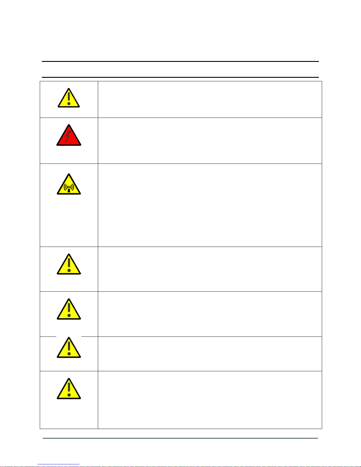
Throughout this manual, there are "Caution" warnings. "Caution" calls attention to a
procedure or practice, which, if ignored, may result in injury or damage to the system, system
component or even the user. Do not perform any procedure preceded by a "Caution" until the
described conditions are fully understood and met.
CAUTION! This notice calls attention to a procedure or practice that, if
ignored, may result in personal injury or in damage to the system or system
component. Do not perform any procedure preceded by a "Caution" until
described conditions are fully understood and met.
Page 4
Axell Wireless Limited
Technical Literature
UHF Dual Band Line Amplifier
Document Number 55-227901HBK
Issue No. 4
Date 23/06/2014
Page 4 of 30
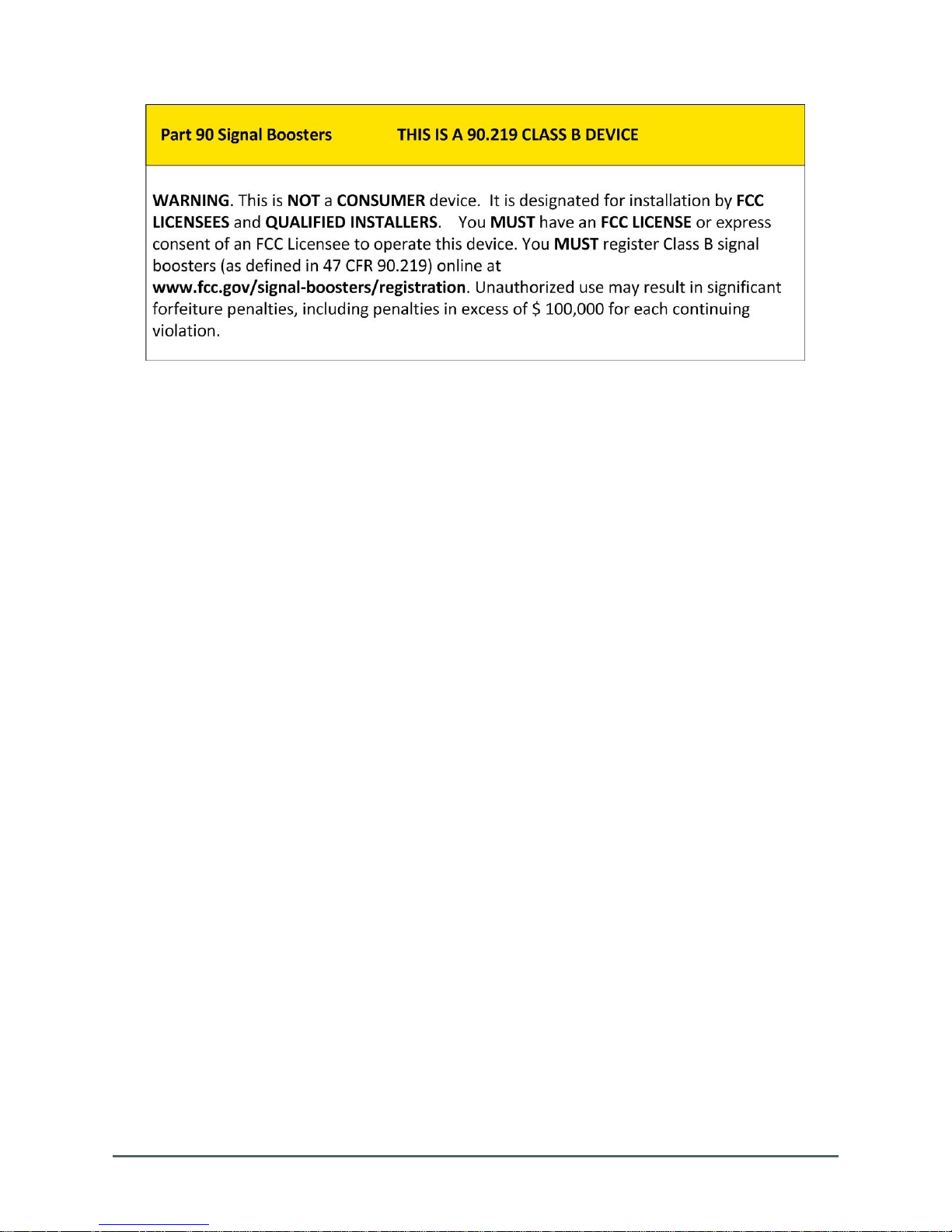
Compliance with FCC
FCC Part 15
This device complies with part 15 of the FCC Rules. Operation is subject to the following two
conditions:
1. This device may not cause harmful interference, and
2. This device must accept any interference received, including interference that may cause
undesired operation.
If not installed and used in accordance with the instructions, this equipment generates, uses and can
radiate radio frequency energy. However, there is no guarantee that interference will not occur in a
particular installation. If this equipment does cause harmful interference to RF reception, which can be
determined by turning the equipment off and on, the user is encouraged to try to correct the
interference by one or more of the following measures:
Ensure that the input levels to the Line Amplifier are correct and that the equipment gain is not
excessive.
Isolate or Relocate the Server Radiating antenna cable.
Connect the equipment into an outlet on a circuit different from that to which the receiver is
connected.
Unauthorized Changes to Equipment
Changes or Modifications not expressly approved by the manufacturer responsible for compliance
could void the user’s authority to operate the equipment
FCC RF Exposure Limits
This unit complies with FCC RF exposure limits for an uncontrolled environment. This equipment can
only be installed in in-building or tunnel applications and must be used as a line driver amplifier to
drive radiating cable systems. There are no antennas used for the radiation, Radiating cables have a
low level of coupling and as such the RF exposure is extremely low. As a precaution it is
recommended that the radiating cable is operated at a minimum distance of 10 cm between the cable
radiator and any person’s body.
Page 5

Axell Wireless Limited
Technical Literature
UHF Dual Band Line Amplifier
Document Number 55-227901HBK
Issue No. 4
Date 23/06/2014
Page 5 of 30
Radiating Antenna Installation
CAUTION! This Equipment is designed as an in-line Radiating Cable booster
and must not be used as a Class B Off-Air repeater.
Installation of a radiating cable antenna must comply with the FCC RF exposure requirements. The
radiating cable used for this transmitter must be mounted on permanent structures.
The FCC regulations mandate that the EIRP of type B signal boosters should not exceed 5W.
The radiating cable associated with In-Line Boosters has a high attenuation of coupling and as such a
negative gain. The Line Amplifier has a maximum amplifier P1dB of +26.5dBm (0.44w), the radiating
cable is typically -50dB radiating loss and therefore the ERP will always be below the 5W limit.
Equation (1) - Max SERVICE antenna gain
Not Applicable – Radiating cable fed equipment.
Equation (2) - Max DONOR antenna gain
Not Applicable – Radiating cable fed equipment
Compliance with FCC deployment rule regarding the radiation of noise
Good engineering practice must be used in regard to the signal booster’s noise radiation. Thus, the
gain of the signal booster should be set so that the EIRP of the output noise from the signal booster
should not exceed the level of -43 dBm in 10 kHz measurement bandwidth.
In the event that the noise level measured exceeds the aforementioned value, the signal booster gain
should be decreased accordingly.
In general, the ERP of noise on a spectrum more than 1 MHz outside of the pass band should not
exceed -70 dBm in a 10 kHz measurement bandwidth.
The WMATA Line Amplifier (55-227901) signal booster has a noise level of below -90 dBm in 10 kHz
measurement at 1 MHz spectrum outside the passband of the signal booster and an in-band noise
level of -60 dBm (worst case) in a 10 kHz bandwidth.
Conclusion:
Good engineering practice requires that in general when the out of band noise measured at the
service antenna input is more than -70 dBm per 10 kHz measurement bandwidth, an external band
pass filter should be added to attenuate the out of band noise level. However, in this application
using radiating cables, No further filtering will be required because of the cable coupling attenuation.
Page 6
Axell Wireless Limited
Technical Literature
UHF Dual Band Line Amplifier
Document Number 55-227901HBK
Issue No. 4
Date 23/06/2014
Page 6 of 30
General Safety Warnings Concerning Use of This System
Always observe standard safety precautions during installation, operation and maintenance of this
product. Only a qualified and authorized personnel should carry out adjustment, maintenance or
repairs to the components of this equipment.
NOTE: Please refer to Axell Wireless for additional information and for requests for notifications to
authorities.
Caution labels!
Throughout this manual, there are "Caution" warnings. "Caution" calls attention to a
procedure or practice, which, if ignored, may result in injury or damage to the system,
system component or even the user. Do not perform any procedure preceded by a
"Caution" until the described conditions are fully understood and met.
Danger:
Electrical Shock
This equipment can either be installed indoors or outdoors. When installed outdoors wet conditions increase the potential for receiving an electric shock when installing or
using electrically powered equipment. To prevent electrical shock when installing or
modifying the system power wiring, disconnect the wiring at the power source before
working with un insulated wires or terminals.
Caution:
RF Exposure
RF radiation, (especially at UHF frequencies) arising from transmitter outputs connected
to AWL’s equipment, must be considered a safety hazard.
This condition might only occur in the event of cable disconnection, or because a ‘spare’
output has been left un-terminated. Either of these conditions would impair the system’s
efficiency. No investigation should be carried out until all RF power sources have been
removed. This would always be a wise precaution, despite the severe mismatch
between the impedance of an N type connector at 50Ω, and that of free space at 377Ω,
which would severely compromise the efficient radiation of RF power. Radio frequency
burns could also be a hazard, if any RF power carrying components were to be
carelessly touched!
Where the equipment is used near power lines or in association with temporary masts
not having lightning protection, the use of a safety earth connected to the case-earthing
bolt is strongly advised.
Caution: Safety to
personnel.
Before installing or replacing any of the equipment, the entire manual should be read
and understood.
The user needs to supply the appropriate AC or DC power to the Line Amplifier.
Incorrect power settings can damage the Line Amplifier and may cause injury to the
user.
Please be aware that the equipment may, during certain conditions become very warm
and can cause minor injuries if handled without any protection, such as gloves
Caution: Safety to
equipment
When installing, replacing or using this product, observe all safety precautions during
handling and operation. Failure to comply with the following general safety precautions
and with specific precautions described elsewhere in this manual violates the safety
standards of the design, manufacture, and intended use of this product.
Axell Wireless assumes no liability for the customer's failure to comply with these
precautions. This entire manual should be read and understood before operating or
maintaining the Line Amplifier.
Warning: Restricted
Access Location
Access to the Axell unit installation location is restricted to SERVICE PERSONNEL and
to USERS who have been instructed on the restrictions and the required precautions to
be taken.
Attention:
Electrostatic
Sensitivity
Observe electrostatic precautionary procedures.
ESD = Electrostatic Discharge Sensitive Device.
Semiconductor transmitters and receivers provide highly reliable performance when
operated in conformity with their intended design. However, a semiconductor may be
damaged by an electrostatic discharge inadvertently imposed by careless handling.
Static electricity can be conducted to the semiconductor chip from the centre pin of the
RF input connector, and through the AC connector pins. When unpacking and otherwise
handling the Line Amplifier, follow ESD precautionary procedures including use of
grounded wrist straps, grounded workbench surfaces, and grounded floor mats.
Page 7

Axell Wireless Limited
Technical Literature
UHF Dual Band Line Amplifier
Document Number 55-227901HBK
Issue No. 4
Date 23/06/2014
Page 7 of 30
Table of Contents
1. Antenna Specifications and Installation Criteria ........................................................................... 8
1.1. Base (Donor) Input ................................................................................................................... 8
1.1.1. Required Input Information ............................................................................................... 8
1.2. Service Antenna Requirements ............................................................................................... 9
1.2.1. Required Radiating Antenna Information .......................................................................... 9
1.3. RF Cabling Requirements ........................................................................................................ 9
2. Pre-Installation Requirements .................................................................................................... 10
2.1. Safety Guidelines ................................................................................................................... 10
2.2. Selecting a Location ............................................................................................................... 10
2.2.1. Cooling and Airflow ......................................................................................................... 10
2.2.2. Wall Compatibility ........................................................................................................... 10
2.2.3. Access to the Line Amplifier ........................................................................................... 10
3. WMATA Dual Band UHF Line Amplifier 55-227901 ................................................................... 11
3.1. Equipment Overview .............................................................................................................. 11
3.2. Theory of operation ................................................................................................................ 11
3.3. System Diagram .................................................................................................................... 12
3.4. Table of Components by Position Number ............................................................................ 13
3.5. Exploded schematic showing Downlink RF path and components ........................................ 14
3.6. Exploded schematic showing Uplink RF path and components ............................................ 15
3.7. Front View .............................................................................................................................. 16
3.8. Side Views ............................................................................................................................. 17
3.9. Interior Picture - Downlink Path ............................................................................................. 18
3.10. Interior Picture - Uplink Path .................................................................................................. 19
3.11. Specification ........................................................................................................................... 20
4. Installation – General Notes ....................................................................................................... 21
4.1. General Remarks ................................................................................................................... 21
4.2. Electrical Connections ........................................................................................................... 21
4.3. RF Connections ..................................................................................................................... 21
4.3.1. Termination of Unused Ports .......................................................................................... 21
4.4. Commissioning ...................................................................................................................... 22
4.5. RF Installation & Gain Calculations ....................................................................................... 22
5. Maintenance ............................................................................................................................... 23
5.1. Fault Finding .......................................................................................................................... 23
5.1.1. Quick Fault Checklist ...................................................................................................... 23
5.1.2 Fault Isolation ..................................................................................................................... 23
5.1.3. Downlink ......................................................................................................................... 24
5.1.4. Uplink .............................................................................................................................. 24
5.1.5. Checking service ............................................................................................................ 24
5.1.6. Fault repair ...................................................................................................................... 24
5.1.7. Service Support .............................................................................................................. 25
5.2. Tools & Test Equipment ......................................................................................................... 25
5.3. Care of Modules ..................................................................................................................... 26
5.3.1. General Comments ......................................................................................................... 26
5.3.2. LNA Replacement (general procedure) .......................................................................... 26
5.3.3. Module Replacement (general procedure) ..................................................................... 26
5.3.4. Power Amplifier Replacement (general procedure) ........................................................ 26
5.3.5. Low Power Amplifier Replacement (general procedure) ................................................ 27
5.3.6. Module Transportation: ................................................................................................... 27
Appendix A ........................................................................................................................................... 28
A.1. Glossary of Terms used in this document .............................................................................. 28
A.2. Key to Drawing Symbols used in this document .................................................................... 29
A.3. Document Amendment Record .............................................................................................. 30
Page 8

Axell Wireless Limited
Technical Literature
UHF Dual Band Line Amplifier
Document Number 55-227901HBK
Issue No. 4
Date 23/06/2014
Page 8 of 30
1. Antenna Specifications and Installation Criteria
WARNING!!!
o This Dual Band Line Amplifier is specifically designed for in-line radiating
cable operation and must not be directly connected to an off air radiating
antenna.
o The installer is held accountable for implementing the rules required for
deployment.
o Good engineering practice must be used to avoid interference.
o Output power should be reduced to solve any IMD interference issues.
This chapter provides information on the donor source feed and server output radiating infrastructure
associated with the Line Amplifier equipment.
1.1. Base (Donor) Input
The Base (Donor) input is normally provided from the attenuated end of an existing radiating cable of
from an in-line coupler used to coupler off a sample of the main line signal for downlink amplification.
In the uplink direction a low level signal is fed back into the donor cable for retransmission to the base
station equipment. The output signal of the Line Amplifier is not transmitted to air.
1.1.1. Required Input Information
You will require the following information:
Number of carriers
Carrier Power
Length and type of radiating coaxial cable connecting the Donor system to the Line Amplifier and
the attenuation.
Page 9

Axell Wireless Limited
Technical Literature
UHF Dual Band Line Amplifier
Document Number 55-227901HBK
Issue No. 4
Date 23/06/2014
Page 9 of 30
1.2. Service Antenna Requirements
WARNING!!!
a. The installer is held accountable for implementing the rules required for
deployment.
b. Good engineering practice must be used to avoid interference.
c. Output power should be reduced to solve any IMD interference issues”
This product is designed as a Line Amplifier repeater to extend the signal coverage distance of a
radiating cable system and must not be used as an off air repeater.
1.2.1. Required Radiating Antenna Information
The following antenna requirements, specifications and site considerations should be met:
Service area type and size
Radiating Cable Coupling factor and longitudinal Attenuation
Distance from Mobile
Mobile Signal = Line Amplifier Output – cable attenuation dB/100ft – cable coupling dB – distance
correction.
e.g. Typical 7/8” cable = loss 0.7dB / 100’ with Coupling Loss 80dB @ 6’
Thus for an 800’ cable with +10dBm input we have:
+10 – (0.7*8) – 80 = -75.6dBm radiated signal from the cable at 6’ distance.
1.3. RF Cabling Requirements
For all coaxial connections to/from the Line Amplifier - high performance, flexible, low loss 50Ω
coaxial communications cable.
All cables shall be weather-resistant type.
Make sure that cable and connector are compatible. Using cables and connectors from the same
manufacturer is helpful.
All connectors must be clean and dry
Waterproof all outdoor connections using silicone, vulcanizable tape or other suitable substance
as moisture and dust can impair RF characteristics.
Make sure enough room has been allocated for the bending radius of the cable. RF cables must
not be kinked, cut or damaged in any way
Use jumper cable for easy installation. The RF Coaxial cable can be substituted at each end with
a jumper cable.
Page 10

Axell Wireless Limited
Technical Literature
UHF Dual Band Line Amplifier
Document Number 55-227901HBK
Issue No. 4
Date 23/06/2014
Page 10 of 30
2. Pre-Installation Requirements
2.1. Safety Guidelines
Before installing the Line Amplifier, review the following safety information:
Follow all local safety regulations when installing the Line Amplifier.
Only qualified personnel are authorized to install and maintain the Line Amplifier.
Ground the Line Amplifier with the grounding bolt located on the underside of the Line Amplifier
Do not use the grounding bolt to connect external devices.
Follow Electro-Static Discharge (ESD) precautions.
2.2. Selecting a Location
Select a location that will take into account the following criteria:
Relative location of Radiating cable system and access
Cooling and airflow
Wall compatibility
Access to the equipment for installation or maintenance
2.2.1. Cooling and Airflow
Install the Line Amplifier in a shielded, ventilated, and easy-to-reach area.
The Line Amplifier is convection cooled so airflow and alternation should be possible.
Verify that ambient temperature of the environment does not exceed 50C (122F)
2.2.2. Wall Compatibility
Check the suitability of the wall on which the Line Amplifier is to be mounted.
The Line Amplifier wall mount brackets assembly should be fixed to a solid wall (these include
brickwork, block work, and concrete.);
(Due to the weight of the Line Amplifier, it is NOT recommended to fix to a hollow wall).
2.2.3. Access to the Line Amplifier
Plan connection cable clearances - the RF and power connections located on the underside of
the Line Amplifier will need at least 12” vertical clearance below the Line Amplifier to enable the
connections to be made. The minimum bend radius for RF cables must not be less than the
recommendations made by the cable manufacturer. Plan the cable runs and ensure adequate
space is available.
Allow for door opening - ensure that there is sufficient space at the front of the Line Amplifier to
allow the door to be fully opened and for maintenance engineers to get access to the unit with test
equipment such as a spectrum analyser.
Allow space around the Line Amplifier - verify that there is a minimum of a 50 cm (20”) radius
of space around the Line Amplifier, enabling easy access to the Line Amplifier for maintenance
and on-site inspection. Allow an additional 50 cm of space in front of the Line Amplifier when the
door is fully open.
Page 11

Axell Wireless Limited
Technical Literature
UHF Dual Band Line Amplifier
Document Number 55-227901HBK
Issue No. 4
Date 23/06/2014
Page 11 of 30
3. WMATA Dual Band UHF Line Amplifier 55-227901
3.1. Equipment Overview
WMATA Dual Band UHF Line Amplifier 55-227901 is a Bi-directional Line Amplifier designed for
Radiating Cable signal extension. The equipment consists of four signal paths (2 downlink and 2
uplink) to provide dual band operation.
The two Downlink bands are: 489.5 MHz – 491.0 MHz & 496.0 MHz – 496.9 MHz.
The two Uplink bands are: 492.5 MHz – 494.0 MHz & 499.0 MHz – 499.9 MHz.
The equipment provides 17dB to 47dB of gain, via a number of amplifiers in each direction. An ALC
system is fitted to each amplifier path to provide Automatic Level Control to prevent signal overload
and interference. High selectivity band pass duplexers are used on both the downlink and uplink
paths to provide isolation between the interleaved frequency bands.
The equipment is built into a wall-mounted, environmentally protected NEMA lockable steel case, the
RF ports and connectors are also NEMA rated to ensure a weatherproof product. A supply isolator
switch is fitted inside the unit and there are Power On and Alarm indicators on the outside of the door.
3.2. Theory of operation
Please refer to system Diagram para 3.3 which identify the component positions thus (x).
The downlink input signal from the proceeding base station feeding radiating cable enters the donor
input port and is fed to a circulator (1) which directs the transmission into the downlink duplexer (2).
The downlink duplexer filters the signal to provide 2 downlink outputs to the amplifier chains. Each
amplifier chain consists of a similar line up of components. The filtered downlink is fed via an
adjustable attenuator (3 or 9) and into a low noise amplifier (4 or 10) which provides 28dB gain. The
amplified signal is then fed via a diode attenuator module (5 or 11) which forms part of the ALC
feedback control loop. The ALC attenuator then feeds the signal into an output amplifier (6 or 12)
which provides 30dB gain but is restricted to 0.4W output power. The downlink signal then passes
through the ALC detector (7 or 13), the ALC detector ensures that should the output power l evel
become equal to or exceed the 0.4W threshold, a control voltage is fed back to the ALC attenuator to
reduce the input drive level to prevent overload of the output amplifier. Following the detector the two
downlink paths are recombined in the output duplexer (8) before passing through the server port
circulator (14) and the 20dB signal monitor tapper (15) and out to the server radiating cable.
The uplink input signal from the mobile feeding radiating cable enters the server input port and is fed
via a 20dB signal monitor tapper (15) to a circulator (14) which directs the transmission into the uplink
duplexer (16). The uplink duplexer filters the signal to provide 2 uplink outputs to the amplifier chains.
Each amplifier chain consists of a similar line up of components. The filtered uplink is fed via a low
noise amplifier (17 or 23) which provides 30dB gain and into an adjustable attenuator (18 or 24). The
signal is then fed via a diode attenuator module (19 or 25) which forms part of the ALC feedback
control loop. The ALC attenuator then feeds the signal into an output amplifier (20 or 26) which
provides 32dB gain being restricted to 0.1W output power. The uplink signal then passes through the
ALC detector (21 or 27), the ALC detector ensures that should the output power level become equal
to or exceed the 0.1W threshold, a control voltage is fed back to the ALC attenuator to reduce the
input drive level to prevent overload of the output amplifier. Following the detector the two downlink
paths are recombined in the output duplexer (8) before passing through the donor port circulator (1)
and out to the base station fed radiating cable.
Page 12

Axell Wireless Limited
Technical Literature
UHF Dual Band Line Amplifier
Document Number 55-227901HBK
Issue No. 4
Date 23/06/2014
Page 12 of 30
55-227901 RF system diagram
With component numbering
Date: 18 February 2014
Page 1 of 1
A4
Drawn by: AJS
Not to Scale
© Axell Wireless 2014
Aerial House
Asheridge Road
Chesham
Buckinghamshire
HP5 2QD United Kingdom
Telephone: +44 (0) 1494 777000
Facsimile: +44 (0) 1494 777002
E-Mail: info@axellwireless.com
www.axellwireless.com
Downlink Input
Uplink Output
Downlink Output
Uplink Input
PA
12-021601
PA
12-021601
+30dB
+30dB
AGC
Attenuator
17-016401
AGC
Attenuator
17-016401
AGC
Attenuator
17-016401
AGC
Attenuator
17-016401
LNA
11-008901
LNA
11-008901
+28dB
+28dB
AGC
Detector
17-019801
AGC
Detector
17-019801
AGC
Detector
17-019801
AGC
Detector
17-019801
Isolator
08-004014
Isolator
08-004014
LPA
12-030301
LPA
12-030301
+32dB
+32dB
LNA
11-007402
LNA
11-007402
+30dB
+30dB
0 – 30dB
Attenuator
10-000701
0 – 30dB
Attenuator
10-000701
0 – 30dB
Attenuator
10-000701
0 – 30dB
Attenuator
10-000701
12V
1.9A
12V
1.9A
12V
0.5A
12V
0.5A
Duplexer
1513001267
Duplexer
1513001266
Duplexer
1513001267
Duplexer
1513001266
12V
0.23A
12V
0.23A
12V
0.33A
12V
0.33A
20dB Non-
directional tap
1510000148
20dBc Test port
AGC
AGC
AGC
AGC
489.5 – 491.0MHz
496.0 – 496.9MHz
492.5 – 494.0MHz
499.0 – 499.9MHz
492.5 – 494.0MHz
499.0 – 499.9MHz
489.5 – 491.0MHz
496.0 – 496.9MHz
1
2
3
8
4
5
6
7
9
10
11
12
13
14
15
16
22
17
18
19
20
21
23
24
25
26
27
3.3. System Diagram
Page 13

Axell Wireless Limited
Technical Literature
UHF Dual Band Line Amplifier
Document Number 55-227901HBK
Issue No. 4
Date 23/06/2014
Page 13 of 30
3.4. Table of Components by Position Number
Component
position
number
Component
description
Component
part
number
1
“Base” port Isolator
08-004014
2
“Base” Downlink Duplexer
1513001267
3
489.5 MHz - 491.0MHz D/L path Variable Switched Attenuator 0-30dB
10-000701
4
489.5 MHz - 491.0MHz D/L path Low Noise Amplifier 28dB Gain
11-008901
5
489.5 MHz - 491.0MHz D/L path AGC Attenuator Module
17-016401
6
489.5 MHz - 491.0MHz D/L path Power Amplifier 20dB Gain
12-021601
7
489.5 MHz - 491.0MHz D/L path AGC Detector Module
17-019801
8
“Mobile” Downlink Duplexer
1513001267
9
496.0 MHz - 496.9MHz D/L path Variable Switched Attenuator 0-30dB
10-000701
10
496.0 MHz - 496.9MHz D/L path Low Noise Amplifier 28dB Gain
11-008901
11
496.0 MHz - 496.9MHz D/L path AGC Attenuator Module
17-016401
12
496.0 MHz - 496.9MHz D/L path Power Amplifier 20dB Gain
12-021601
13
496.0 MHz - 496.9MHz D/L path AGC Detector Module
17-019801
14
“Mobile” port Isolator
08-004014
15
Power Tapper 20dB
1510000148
16
“Mobile” Uplink Duplexer
1513001266
17
492.5 MHz - 494.0MHz U/L path Low Noise Amplifier 30dB Gain
11-007402
18
492.5 MHz - 494.0MHz U/L path Variable Switched Attenuator 0-30dB
10-000701
19
492.5 MHz - 494.0MHz U/L path AGC Attenuator Module
17-016401
20
492.5 MHz - 494.0MHz U/L path Low Power Amplifier 33dB Gain
12-030301
21
492.5 MHz - 494.0MHz U/L path AGC Detector Module
17-019801
22
“Base” Uplink Duplexer
1513001266
23
499.0 MHz - 499.9MHz U/L path Low Noise Amplifier 30dB Gain
11-007402
24
499.0 MHz - 499.9MHz U/L path Variable Switched Attenuator 0-30dB
10-000701
25
499.0 MHz - 499.9MHz U/L path AGC Attenuator Module
17-016401
26
499.0 MHz - 499.9MHz U/L path Low Power Amplifier 33dB Gain
12-030301
27
499.0 MHz - 499.9MHz U/L path AGC Detector Module
17-019801
Page 14

Axell Wireless Limited
Technical Literature
UHF Dual Band Line Amplifier
Document Number 55-227901HBK
Issue No. 4
Date 23/06/2014
Page 14 of 30
#6
#17
#20
#27 #19
#25 #21
#23
#13 #5
#11 #7
#2#22#16#8
#3
#9
#18
#24
#1#14
#15
#26
#12
#4
#10
D/L I/P
U/L O/P
D/L O/P
U/L I/P
20dB
Test Port
Date: 18 February 2014
© AWL 2014
Page 1 of 1
Size: A4
Issue: 1
Drawn by: AJS
Not to Scale
55-227901 Exploded schematic
showing Downlink RF path and components
Aerial House
Asheridge Road
Chesham
Buckinghamshire
HP5 2QD United Kingdom
Telephone: +44 (0) 1494 777000
Facsimile: +44 (0) 1494 777002
E-Mail: info@axellwireless.com
www.axellwireless.com
axell
WIR E LESS
3.5. Exploded schematic showing Downlink RF path and components
Page 15

Axell Wireless Limited
Technical Literature
UHF Dual Band Line Amplifier
Document Number 55-227901HBK
Issue No. 4
Date 23/06/2014
Page 15 of 30
#6
#17
#20
#27 #19
#25 #21
#23
#13 #5
#11 #7
#2#22#16#8
#3
#9
#18
#24
#1#14
#15
#26
#12
#4
#10
D/L I/P
U/L O/P
D/L O/P
U/L I/P
20dB
Test Port
Date: 18 February 2014
© AWL 2014
Page 1 of 1
Size: A4
Issue: 1
Drawn by: AJS
Not to Scale
55-227901 Exploded schematic
showing Uplink RF path and components
Aerial House
Asheridge Road
Chesham
Buckinghamshire
HP5 2QD United Kingdom
Telephone: +44 (0) 1494 777000
Facsimile: +44 (0) 1494 777002
E-Mail: info@axellwireless.com
www.axellwireless.com
axell
WIR ELES S
3.6. Exploded schematic showing Uplink RF path and components
Page 16

Axell Wireless Limited
Technical Literature
UHF Dual Band Line Amplifier
Document Number 55-227901HBK
Issue No. 4
Date 23/06/2014
Page 16 of 30
3.7. Front View
A
Green LED “POWER ON” illuminated during normal operating conditions
B
Red LED “ALARM” illuminated during alarm conditions
C
Door locks
D
Lifting handles
E
FCC Compliance label
Page 17

Axell Wireless Limited
Technical Literature
UHF Dual Band Line Amplifier
Document Number 55-227901HBK
Issue No. 4
Date 23/06/2014
Page 17 of 30
3.8. Side Views
A
Common RF port D/L I/P and U/L O/P, “Base” port
B
Common RF port D/L O/P and U/L I/P, “Mobile” port
C
20dB test/monitor port
D
3 Pole panel plug, AC Input
E
6 Pole panel plug, Alarm Output
F
Grounding connection
G
Position of wall mount brackets (not fitted at time of photography)
Page 18

Axell Wireless Limited
Technical Literature
UHF Dual Band Line Amplifier
Document Number 55-227901HBK
Issue No. 4
Date 23/06/2014
Page 18 of 30
3.9. Interior Picture - Downlink Path
A
Common RF port D/L I/P and U/L O/P, “Base” port
B
“Base” port Isolator
C
“Base” port Downlink Duplexer - position of, behind panel
D
489.5 MHz - 491.0MHz Downlink path Variable Attenuator
E
496.0 MHz - 496.9MHz Downlink path Variable Attenuator
F
Downlink paths Low Noise Amplifiers and AGC Detector and Attenuator Modules
G
489.5 MHz - 491.0MHz Downlink path Power Amplifier
H
496.0 MHz - 496.9MHz Downlink path Power Amplifier
I
“Mobile” port Downlink Duplexer - position of, behind panel
J
“Mobile” port Isolator
K
20dB Non-directional Tap
L
Common RF port D/L O/P and U/L I/P, “Mobile” port
M
20dB test/monitor port
N
Position of AC input and Alarm output
O
AC trip switch (96-300042)
P
PSU module (96-300052)
Q
12V Relay PCB Assembly (80-008909)
Page 19

Axell Wireless Limited
Technical Literature
UHF Dual Band Line Amplifier
Document Number 55-227901HBK
Issue No. 4
Date 23/06/2014
Page 19 of 30
3.10. Interior Picture - Uplink Path
A
Common RF port U/L I/P and D/L O/P, “Mobile” port
B
20dB test/monitor port
C
20dB Non-directional Tap
D
“Mobile” port Isolator
E
“Mobile” port Uplink Duplexer - position of, behind panel
F
492.5 MHz - 494.0MHz Uplink path Variable Attenuator
G
499.0 MHz - 499.9MHz Uplink path Variable Attenuator
H
Uplink paths Low Noise Amplifiers and AGC Detector and Attenuator Modules
I
492.5 MHz - 494.0MHz Uplink path Low Power Amplifier
J
499.0 MHz - 499.9MHz Uplink path Low Power Amplifier
K
“Base” port Uplink Duplexer - position of, behind panel
L
“Base” port Isolator
M
Common RF port U/L O/P and D/L I/P, “Base” port
N
Position of AC input and Alarm output
O
AC trip switch (96-300042)
P
PSU module (96-300052)
Q
12V Relay PCB Assembly (80-008909)
Page 20

Axell Wireless Limited
Technical Literature
UHF Dual Band Line Amplifier
Document Number 55-227901HBK
Issue No. 4
Date 23/06/2014
Page 20 of 30
LOCATION
KEY
PIN 1PIN 6
PIN 2PIN 5
PIN 3PIN 4
3.11. Specification
Parameter
Specification
Downlink
Frequency Range Band 1
489.5 – 491.0MHz
Frequency Range Band 2
496.0 – 496.9MHz
Maximum Gain
47dB
Gain Adjustment (manual adjustment)
0 – 30dB in 2dB steps
Output Test Port
20dBc
Maximum RF Output Power
+26dBm (AGC limit for FCC)
In-Band Spurious Noise (30kHz B/W)
< -30dBm
Uplink
Frequency Range Band 1
492.5 – 494.0MHz
Frequency Range Band 2
499.0 – 499.9MHz
Maximum Gain
47dB
Gain Adjustment (manual adjustment)
0 – 30dB in 1dB steps
Maximum RF Output Power
+20dBm (AGC limit for FCC)
Noise Figure
6dB
In-Band Spurious Noise (30kHz B/W)
< -30dBm
General
Case Size H x W x D
26.5” x 22.25” x 13”
Case Material
Steel
Case Finish
ANSI-61 Powder Coat
AC Supply Voltage
110V
RF Connectors
N type female
Alarms Fitted
(1)
Summary Alarm Output
Volt free dry contact
Temperature Range
operation
-4°F to +140°F
storage
-40°F to +158°F
Humidity
95% RHNC
(1)
Volt free dry contact, Alarm connector pins 1 & 2
Closed = Good, Open = Alarm
Page 21

Axell Wireless Limited
Technical Literature
UHF Dual Band Line Amplifier
Document Number 55-227901HBK
Issue No. 4
Date 23/06/2014
Page 21 of 30
4. Installation – General Notes
4.1. General Remarks
When this equipment is initially commissioned, please keep a record of the initial set-up parameters,
this will help both the installation personnel and Axell Wireless should these figures be needed for
future reference or diagnosis.
The procedure for installing and commissioning an Axell Wall Mount Line Amplifier is generally as
follows:
1) Secure the Line Amplifier in the chosen wall position.
2) Fix the antenna and connect its cables to the Amplifier antenna ports.
3) Connect a suitable mains or battery power supply to the Amplifier
4) Calculate the attenuation settings required for the uplink and the downlink paths, and set the
attenuators as described elsewhere in this document.
5) Switch the equipment mains on with the small switch located inside the Amplifier on the lower
right hand side of the case.
6) If Input RF is available, then make test calls via the Amplifier to ensure correct operation, if
possible monitoring the signal levels during these calls to ensure that the uplink and downlink
RF levels are as anticipated.
4.2. Electrical Connections
It is recommended that the electrical mains connection is made by a qualified electrician, who must be
satisfied that the supply will be the correct voltage and of sufficient capacity.
All electrical and RF connections should be completed and checked prior to power being applied for
the first time.
Ensure that connections are kept clean and are fully tightened.
4.3. RF Connections
Care must be taken to ensure that the correct connections are made with particular attention made to
the base station TX/RX ports. In the event that the base transmitter is connected to the RX output of
the equipment, damage to the equipment will be done if the base station transmitter is then keyed.
4.3.1. Termination of Unused Ports
In the event that any RF ports are unused (available for future expansion) these ports must be kept
terminated with the load terminations supplied by Axell for that purpose
Ensure that connections are kept clean and are fully tightened.
Page 22

Axell Wireless Limited
Technical Literature
UHF Dual Band Line Amplifier
Document Number 55-227901HBK
Issue No. 4
Date 23/06/2014
Page 22 of 30
4.4. Commissioning
Once all connections are made the equipment is ready for commissioning.
To commission the system the test equipment detailed in Section 5.2. will be required.
Using the system diagrams and the end-to-end test specification (supplied with the equipment), the
equipment should be tested to ensure correct operation. Typical RF levels that are not listed in the
end-to-end specification, such as input levels to the fibre transmitters are detailed in the maintenance
section of this manual.
On initial power up the system alarm indicators on the front door of the equipment should be checked.
A green LED on the front door of the unit illuminates to indicate that the power supply is connected to
the unit
In the event that any part of the system does not function correctly as expected, check all connections
to ensure that they are to the correct port, that the interconnecting cables are not faulty and that they
are tightened. The majority of commissioning difficulties arise from problems with the interconnecting
cables and connectors.
4.5. RF Installation & Gain Calculations
1. Ensure that the in-line amplifier gain is set to minimum. Measure the signal level from the
donor feeding cable and coupler to ascertain the RF input level and gain required.
Note: Ensure that the number of potential carriers is known for the operating band.
2. The equipment gain is set by setting the variable switched attenuators in each path (uplink
and downlink) refer to the photographs and layout drawings for the exact attenuator
locations). Note that the uplink (mobile to base) and downlink (base to mobile) path gains are
set independently. This allows the paths to have different gains if required to set the correct
output power levels.
3. It is recommended that the gains are set such that the Downlink channel output levels from
the equipment are typically +10dBm per channel
(Input level + Gain = Output level).
Page 23

Axell Wireless Limited
Technical Literature
UHF Dual Band Line Amplifier
Document Number 55-227901HBK
Issue No. 4
Date 23/06/2014
Page 23 of 30
5. Maintenance
5.1. Fault Finding
5.1.1. Quick Fault Checklist
All Axell equipment is individually tested to specification prior to despatch. Failure of this type of
equipment is not common. Experience has shown that a large number of fault conditions relating to
tunnel installations result from simple causes often occurring as result of transportation, unpacking
and installation. Below are listed some common problems which have resulted in poor performance or
an indicated non-functioning of the equipment.
Mains power not connected or not switched on.
External connectors not fitted or incorrectly fitted.
Internal connectors becoming loose due to transport vibration.
Wiring becoming detached as a result of heavy handling.
Input signals not present due to faults in the preceding feeder system.
Base transmissions not present due to fault at the base station.
Modems fitted with incorrect software configuration.
5.1.2 Fault Isolation
In the event that the performance of the system is suspect, a methodical and logical approach to the
problem will reveal the cause of the difficulty. The System consists of modules fitted in a wall
mounted, environmentally protected enclosure.
Transmissions from the main base stations are passed through the system to the mobile radio
equipment; this could be a handheld radio or a transceiver in a vehicle. This path is referred to as the
downlink. The return signal path from the mobile radio equipment to the base station is referred to as
the uplink.
The first operation is to check the alarms of each of the active units and determine that the power
supplies to the equipment are connected and active.
If an amplifier is suspect, check the DC power supply to the unit. If no other fault is apparent use a
spectrum analyser to measure the incoming signal level at the input and then after reconnecting the
amplifier input, measure the output level. Consult with the system diagram to determine the expected
gain and compare result.
In the event that there are no alarms on and all units appear to be functioning it will be necessary to
test the system in a systematic manner to confirm correct operation.
Page 24

Axell Wireless Limited
Technical Literature
UHF Dual Band Line Amplifier
Document Number 55-227901HBK
Issue No. 4
Date 23/06/2014
Page 24 of 30
5.1.3. Downlink
Confirm that there is a signal at the expected frequency and RF level from the proceeding cable. If
this is not present then the fault may lay outside the system.
If a signal is not received at the output it will be necessary to follow the downlink path through the
system to find a point at which the signal is lost. The expected downlink output for the given input can
be found in the end-to-end test specification.
5.1.4. Uplink
Testing the uplink involves a similar procedure to the downlink except that the frequencies used are
those transmitted by the mobile equipment.
5.1.5. Checking service
Following the repair of any part of the system it is recommended that a full end-to-end test is carried
out in accordance with the test specification and that the coverage is checked by survey.
It is important to bear in mind that the system includes a radiating cable network and base stations
that may be faulty or may have been damaged.
5.1.6. Fault repair
Once a faulty component has been identified, a decision must be made on the appropriate course to
carry out a repair. A competent engineer can quickly remedy typical faults such as faulty connections
or cables. The exceptions to this are cable assemblies connecting band pass filter assemblies that
are manufactured to critical lengths to maintain a 50-ohm system.
Care should be taken when replacing cables or connectors to ensure that items are of the correct
specification. The repair of component modules such as amplifiers and band pass filters will not
usually be possible in the field, as they frequently require specialist knowledge and test equipment to
ensure correct operation. It is recommended that items of this type are replaced with a spare unit and
the faulty unit returned to Axell Wireless for repair.
Page 25

Axell Wireless Limited
Technical Literature
UHF Dual Band Line Amplifier
Document Number 55-227901HBK
Issue No. 4
Date 23/06/2014
Page 25 of 30
5.1.7. Service Support
Advice and assistance with maintaining and servicing this system are available by contacting
Axell Wireless Ltd., see Contact Information.
NOTE
Individual modules are not intended to be repaired on site and attempts at repair will
invalidate active warranties. Company policy is that individual modules should be repaired
by replacement. Axell Wireless Ltd. maintains a level of stock of most modules which can
usually be despatched at short notice to support this policy.
5.2. Tools & Test Equipment
The minimum tools and test equipment needed to successfully service this Axell Wireless product
are as follows:-
Spectrum analyser
100kHz to 2GHz (Dynamic range = 90dB).
Signal Generator
30MHz to 2GHz (-120dBm to 0dBm o/p level).
Attenuator
20dB, 10W, DC-2GHz, (N male – N female).
Test Antenna
Yagi or dipole for operating frequency.
Digital multi-meter
Universal Volt-Ohm-Amp meter.
Test cable x 2
N male – N male, 2M long RG214.
Test cable x 2
SMA male – N male, 1m long RG223.
Hand tools
Philips #1&2 tip screwdriver.
3mm flat bladed screwdriver.
SMA spanner and torque setter.
Page 26

Axell Wireless Limited
Technical Literature
UHF Dual Band Line Amplifier
Document Number 55-227901HBK
Issue No. 4
Date 23/06/2014
Page 26 of 30
5.3. Care of Modules
5.3.1. General Comments
Many of the active modules contain semiconductor devices utilising MOS technology, which can be
damaged by electrostatic discharge. Correct handling of such modules is mandatory to ensure their
long-term reliability.
To prevent damage to a module, it must be withdrawn and inserted with care. The module may have
connectors on its underside, which might not be visible to the service operative.
5.3.2. LNA Replacement (general procedure)
The following general instructions should be followed to remove a module:
1) Remove power to the unit
2) Remove all visible connectors (RF, DC & alarm)
3) Release module retaining screws.
4) Slowly but firmly, pull the module straight out of its position. Take care not to twist/turn the
module during withdrawal. (When the module is loose, care may be needed, as there may be
concealed connections underneath).
5.3.3. Module Replacement (general procedure)
1) Carefully align the module into its location then slowly push the module directly straight into its
position, taking care not to twist/turn it during insertion.
2) Reconnect all connectors, RF, alarm, power etc., (concealed connectors may have to be
connected first).
3) Replace retaining screws (if any).
4) Double-check all connections before applying power.
5.3.4. Power Amplifier Replacement (general procedure)
1) Remove power to the unit. (Switch off at mains/battery, or remove DC in connector)
2) Remove alarm wires from alarm screw terminal block or disconnect multi-way alarm
connector.
3) Carefully disconnect the RF input and output coaxial connectors (usually SMA)
If alarm board removal is not required, go to step 5.
4) There is (usually) a plate attached to the alarm board which fixes it to the amplifier, remove its
retaining screws and the alarm board can be withdrawn from the amplifier in its entirety. On
certain types of amplifier the alarm board is not mounted on a dedicated mounting plate; in this
case it will have to firstly be removed by unscrewing it from the mounting pillars, in most
cases, the pillars will not have to be removed before lifting the amplifier.
5) If the amplifier to be removed has a heatsink attached, there may be several different ways it
can have been assembled. The most commonly used method, is screws through the front of
the heatsink to threaded screw holes (or nuts and bolts), into the amplifier within the main
case. If the heatsink is mounted on the rear of the main case (e.g., against a wall in the case
of wall mounted enclosures), then the fixing method for the heatsink will be from within the
case, (otherwise the enclosure would have to be removed from the wall in order to remove the
heatsink).
Page 27

Axell Wireless Limited
Technical Literature
UHF Dual Band Line Amplifier
Document Number 55-227901HBK
Issue No. 4
Date 23/06/2014
Page 27 of 30
When the heatsink has been removed, the amplifier may be unscrewed from the main casing by its
four corner fixings and gently withdrawn.
Fitting a new power amplifier module will be the exact reverse of the above.
Note: Do not forget to apply fresh heatsink compound to the heatsink/main case joint and also
between the amplifier and the main case.
5.3.5. Low Power Amplifier Replacement (general procedure)
Disconnect the mains power supply and disconnect the 24V dc supply connector for the LPA.
Disconnect the RF input and output cables from the LPA.
Disconnect the alarm connector.
Remove the LPA module by removing the four retaining screws, replace with a new LPA
module and secure it with the screws.
Connect the RF cables to the LPA input and output connectors.
Reconnect the DC supply connector and turn the mains switch on.
Note: Tighten SMA connectors using only a dedicated SMA torque spanner. If SMA connectors are
over-tightened, irreparable damage will occur. Do not use adjustable pliers to loosen/tighten SMA
connectors.
Also take care not to drop or knock the module as this can damage (or misalign in the case of tuned
passive modules) sensitive internal components. Always store the modules in an environmentally
friendly location
5.3.6. Module Transportation:
To maintain the operation, performance and reliability of any module it must be stored and
transported correctly. Any module not installed in a whole system must be kept in an anti-static bag or
container. These bags or containers are normally identified by being pink or black, and are often
marked with an ESD label. Any module sent back to Axell Wireless for investigation/repair must be so
protected. Please contact the Axell Wireless Network Services Support Desk before returning a
module.
Page 28

Axell Wireless Limited
Technical Literature
UHF Dual Band Line Amplifier
Document Number 55-227901HBK
Issue No. 4
Date 23/06/2014
Page 28 of 30
Appendix A
A.1. Glossary of Terms used in this document
Repeater or
Cell Enhancer
A Radio Frequency (RF) amplifier which can simultaneously amplify and re-broadcast
Mobile Station (MS) and Base Transceiver Station (BTS) signals.
Band Selective
Repeater
A Repeater designed for operation on a range of channels within a specified frequency
band.
Channel Selective
Repeater
A Repeater, designed for operation on specified channel(s) within a specified frequency
band. Channel frequencies may be factory set or on-site programmable.
AC
Alternating Current
AEM
Axell Element Manager (Network control and monitoring software)
AGC
Automatic Gain Control
BBU
Battery Backup Unit
BDA
Bi-directional Amplifier
BTS
Base Transceiver Station (Base Station)
B/W
Bandwidth
C/NR
Carrier-to-Noise Ratio
Critical Harness
A coaxial cable harness with components of a critical length used to minimise phase
discrepancies when joining signal paths of differing frequencies.
DAS
Distributed Antenna System
DC
Direct Current
Downlink (D/L)
Signals transmitted from the BTS to the Mobiles
DSP
Digital Signal Processing
F/O
Fibre Optic
GND
Ground
ID
Identification (Number)
I/P
Input
LCX
Leaky Coaxial Cable (Leaky Feeder).
LED
Light Emitting Diode
LNA
Low Noise Amplifier
LPA
Low Power Amplifier
Mobile(s)
Hand-portable or other “Mobile” RF Transceiver equipment
MOU
Master Optical Unit
MTBF
Mean Time Between Failures
N/A
Not Applicable
N/C (of Relays)
Normally Closed
N/O (of Relays)
Normally Open
OFR
On Frequency Repeater
OIP3
Output Third Order Intercept Point
O/P
Output
P1dB
1dB Compression Point
PA
Power Amplifier
RF
Radio Frequency
RHNC
Relative Humidity, Non Condensing
RMC
Repeater Maintenance Console (a GUI based Repeater management application)
RSA
Receiver/Splitter Amplifier
RX
Receiver (Received)
SDR
Software-Defined Radio
S/N
Serial Number
TX
Transmitter (Transmitted)
Uplink (U/L)
Signals transmitted from the Mobiles to the BTS
UPS
Uninterruptible Power Supply
VSWR
Voltage Standing Wave Ratio
WDM
Wave division multiplex
Date Format
Date Format used in this document is dd/mm/yyyy
Page 29

Axell Wireless Limited
Technical Literature
UHF Dual Band Line Amplifier
Document Number 55-227901HBK
Issue No. 4
Date 23/06/2014
Page 29 of 30
A.2. Key to Drawing Symbols used in this document
Page 30

Axell Wireless Limited
Technical Literature
UHF Dual Band Line Amplifier
Document Number 55-227901HBK
Issue No. 4
Date 23/06/2014
Page 30 of 30
A.3. Document Amendment Record
Issue
No.
Date
Incorporated
by
Section
Amended
Reason for new issue
1
10/01/2014
AJS
Draft
2
18/02/2014
AJS
Issue
3
17/06/2014
AJS
FCC compliance changes
 Loading...