

Page 1

UHF Bandselective Bi-Directional Amplifier
90dB 40/5W
User/Maintenance Handbook
For
Pacific Wireless Communications L.L.C.
AFL Works Order Q116107
AFL Product Part No. 55-199102
Aerial Facilities Limited
Technical Literature
Document Number 55-199102HBKM Issue No. 1 Date 05/10/2007 Page 1 of 28
UHF Bandselective BDA
90dB 40/5W
Page 2

Table of Contents
1. INTRODUCTION..........................................................................................................................3
1.1. Scope and Purpose of Document ............................................................................................. 3
1.2. Limitation of Liability Notice ......................................................................................................3
2. SAFETY CONSIDERATIONS......................................................................................................4
2.1. Earthing of Equipment ..............................................................................................................4
2.2. Electric Shock Hazard............................................................................................................... 4
2.3. RF Radiation Hazard ................................................................................................................4
2.4. Lifting and other Health and Safety Recommendations............................................................ 4
2.5. Chemical Hazard ......................................................................................................................5
2.6. Laser safety ..............................................................................................................................5
2.7. Emergency Contact Numbers...................................................................................................5
3. EQUIPMENT OVERVIEW............................................................................................................6
3.1. UHF Bandselective, BDA (55-199102) List of major sub modules ...........................................7
3.2. UHF Bandselective, BDA (55-199102) Specification................................................................7
3.3. UHF Bandselective, BDA (55-199102) System Schematic..........................................................8
3.4. Photographs.............................................................................................................................. 9
3.4.1. Front of case – door closed................................................................................................ 9
3.4.2. Front of case – door open ................................................................................................ 10
3.4.3. Right Hand and Left Hand sides ...................................................................................... 11
4. UHF BANDSELECTIVE, BDA (55-199102) SUB MODULES...................................................12
4.1. Bandpass Filter (02-010701) ..................................................................................................12
4.2. 3dB Splitter/Combiner (05-002603) ........................................................................................13
4.3. Remote Attenuator Switch Assembly (‘10-001725’) ...............................................................13
4.4. 5 Watt Tetra Amplifier (12-021601)......................................................................................... 14
4.5. Linearised Power Amplifier (12-026901)................................................................................. 15
4.6. Voltage Regulator Board 9.0V (13-001714)............................................................................ 16
4.7. DC/DC Converter, 24V in, 12V 8A out (13-003011) ...............................................................16
4.8. Bi-Directional Amplifier (17-017301) ....................................................................................... 17
4.9. 12V (Single) Relay Board (80-008901)...................................................................................18
4.10. 24V Switch-Mode PSU (96-300054).................................................................................... 18
5. INSTALLATION & COMMISIONING.........................................................................................19
5.1. Antenna Installation & Gain Calculations................................................................................ 19
5.2. Initial Installation Record......................................................................................................... 19
6. FAULT FINDING / MAINTENANCE.......................................................................................... 20
6.1. Tools & Test Equipment.......................................................................................................... 20
6.2. Basic Fault Finding .................................................................................................................20
6.3. Quick Fault Checklist .............................................................................................................. 21
6.4. Downlink ................................................................................................................................. 21
6.5. Uplink......................................................................................................................................21
6.6. Fault repair.............................................................................................................................. 21
6.7. Service Support ......................................................................................................................21
6.8. Care of Modules...................................................................................................................... 22
6.9. Module Removal (LNAs, general procedure):......................................................................... 22
6.10. Module Replacement (general): ..........................................................................................22
6.11. Power Amplifiers.................................................................................................................. 22
6.12. Low Power Amplifier Replacement......................................................................................23
6.13. Module Transportation:........................................................................................................ 23
APPENDIX A.......................................................................................................................................24
A.1. Glossary of Terms used in this document ...........................................................................24
A.2. Key to Drawing Symbols used in this document.................................................................. 25
A.3. EC Declaration of Conformity .............................................................................................. 26
A.4. Amendment List Record Sheet............................................................................................ 27
APPENDIX B.......................................................................................................................................28
Initial Equipment Set-Up Calculations...............................................................................................28
UHF Bandselective BDA
90dB 40/5W
Document Number 55-199102HBKM Issue No. 1 Page 2 of 28
Page 3

1. INTRODUCTION
1.1. Scope and Purpose of Document
This handbook is for use solely with the equipment identified by the Aerial Facilities Limited (AFL) Part
Number shown on the front cover. It is not to be used with any other equipment unless specifically
authorised by AFL. This is a controlled release document and, as such, becomes a part of Aerial
Facilities’ Total Quality Management System. Alterations and modification may therefore only be
performed by AFL.
AFL recommends that the installer of this equipment familiarise themselves with the safety and
installation procedures contained within this document before installation commences.
The purpose of this handbook is to provide the user/maintainer with sufficient information to service
and repair the equipment to the level agreed. Maintenance and adjustments to any deeper level must
be performed by AFL, normally at the company’s repair facility in Chesham, England.
This handbook has been prepared in accordance with BS 4884, and AFL’s Quality procedures, which
maintain the company’s registration to BS EN ISO 9001:2000 and to the R&TTE Directive of the
European Parliament. Copies of the relevant certificates and the company Quality Manual can be
supplied on application to the Quality Manager.
This document fulfils the relevant requirements of Article 6 of the R&TTE Directive.
1.2. Limitation of Liability Notice
This manual is written for the use of technically competent operators/service persons. No liability is
accepted by AFL for use or misuse of this manual, the information contained therein, or the
consequences of any actions resulting from the use of the said information, including, but not limited
to, descriptive, procedural, typographical, arithmetical, or listing errors.
Furthermore, AFL does not warrant the absolute accuracy of the information contained within this
manual, or its completeness, fitness for purpose, or scope.
AFL has a policy of continuous product development and enhancement, and as such, reserves the
right to amend, alter, update and generally change the contents, appearance and pertinence of this
document without notice.
All AFL products carry a twelve month warranty from date of shipment. The warranty is expressly on a
return to base repair or exchange basis and the warranty cover does not extend to on-site repair or
complete unit exchange.
UHF Bandselective BDA
90dB 40/5W
Document Number 55-199102HBKM Issue No. 1 Page 3 of 28
Page 4
2. SAFETY CONSIDERATIONS
2.1. Earthing of Equipment
Equipment supplied from the mains must be connected to grounded outlets and earthed
in conformity with appropriate local, national and international electricity supply and
safety regulations.
2.2. Electric Shock Hazard
The risk of electrical shocks due to faulty mains driven power supplies whilst
potentially ever present in any electrical equipment, would be minimised by adherence
to good installation practice and thorough testing at the following stages:
a) Original assembly.
b) Commissioning.
c) Regular intervals, thereafter.
All test equipment must be in good working order prior to its use. High current power supplies can be
dangerous because of the possibility of substantial arcing. Always switch off during disconnection and
reconnection.
2.3. RF Radiation Hazard
RF radiation, (especially at UHF frequencies) arising from transmitter outputs
connected to AFL’s equipment, must be considered a safety hazard.
This condition might only occur in the event of cable disconnection, or because a
‘spare’ output has been left un-terminated. Either of these conditions would impair the
system’s efficiency. No investigation should be carried out until
removed. This would always be a wise precaution, despite the severe mismatch between the
impedance of an N type connector at 50, and that of free space at 377, which would severely
mitigate against the efficient radiation of RF power. Radio frequency burns could also be a hazard, if
any RF power carrying components were to be carelessly touched!
Antenna positions should be chosen to comply with requirements (both local & statutory) regarding
exposure of personnel to RF radiation. When connected to an antenna, the unit is capable of
producing RF field strengths, which may exceed guideline safe values especially if used with
antennas having appreciable gain. In this regard the use of directional antennas with backscreens
and a strict site rule that personnel must remain behind the screen while the RF power is on, is
strongly recommended.
Where the equipment is used near power lines or in association with temporary masts not having
lightning protection, the use of a safety earth connected to the case-earthing bolt is strongly advised.
2.4. Lifting and other Health and Safety Recommendations
Certain items of AFL equipment are heavy and care should be taken when lifting them
by hand. Ensure that a suitable number of personnel, appropriate lifting apparatus
and appropriate personal protective equipment is used especially when installing Cell
Enhancers above ground e.g. on a mast or pole.
all RF power sources have been
UHF Bandselective BDA
90dB 40/5W
Document Number 55-199102HBKM Issue No. 1 Page 4 of 28
Page 5
2.5. Chemical Hazard
Beryllium Oxide, also known as Beryllium Monoxide, or Thermalox™, is sometimes
used in devices within equipment produced by Aerial Facilities Ltd. Beryllium oxide
dust can be toxic if inhaled, leading to chronic respiratory problems. It is harmless if
ingested or by contact.
Products that contain beryllium are load terminations (dummy loads) and some power amplifiers.
These products can be identified by a yellow and black “skull and crossbones” danger symbol (shown
above). They are marked as hazardous in line with international regulations, but pose no threat under
normal circumstances. Only if a component containing beryllium oxide has suffered catastrophic
failure, or exploded, will there be any danger of the formation of dust. Any dust that has been created
will be contained within the equipment module as long as the module remains sealed. For this reason,
any module carrying the yellow and black danger sign should not be opened. If the equipment is
suspected of failure, or is at the end of its life-cycle, it must be returned to Aerial Facilities Ltd for
disposal.
To return such equipment, please contact the Quality Department, who will give you a Returned
Materials Authorisation (RMA) number. Please quote this number on the packing documents, and on
all correspondence relating to the shipment.
PolyTetraFluoroEthylene, (P.T.F.E.) and P.T.F.E. Composite Materials
Many modules/components in AFL equipment contain P.T.F.E. as part of the RF insulation barrier.
This material should never be heated to the point where smoke or fumes are evolved. Any person
feeling drowsy after coming into contact with P.T.F.E. especially dust or fumes should seek medical
attention.
2.6. Laser safety
General good working practices adapted from
EN60825-2: 2004/ EC 60825-2:2004
Do not stare with unprotected eyes or with any unapproved optical device at the fibre
ends or connector faces or point them at other people, Use only approved filtered or attenuating
viewing aids.
Any single or multiple fibre end or ends found not to be terminated (for example, matched, spliced)
shall be individually or collectively covered when not being worked on. They shall not be readily
visible and sharp ends shall not be exposed.
When using test cords, the optical power source shall be the last connected and the first
disconnected; use only approved methods for cleaning and preparing optical fibres and optical
connectors.
Always keep optical connectors covered to avoid physical damage and do not allow any dirt/foreign
material ingress on the optical connector bulkheads.
The optical fibre jumper cable maximum bend radius is 3cm; any smaller radii may result in optical
cable breakage or excessive transmission losses.
Caution: The FO units are
NOT weather proof.
2.7. Emergency Contact Numbers
The AFL Quality Department can be contacted on:
Telephone +44 (0)1494 777000
Fax. +44 (0)1494 777002
e-mail
qa@aerialfacilities.com
UHF Bandselective BDA
90dB 40/5W
Document Number 55-199102HBKM Issue No. 1 Page 5 of 28
Page 6

3. EQUIPMENT OVERVIEW
The AFL UHF Bandselective, Bi-Directional Amplifier (BDA) (55-199102) is a 2-way on-band repeater.
The equipment is supplied in a four-point, wall-mounting, environmentally protected (IP65) aluminium
alloy lockable case. All RF ports and connectors are also IP65 standard making the entire enclosure
and connecting ports weatherproof. Handles are provided for carrying the unit and the door is fitted
with locks. A supply isolator switch is fitted inside the unit and there are D.C. and Alarm On indicators
on the outside of the door.
The UHF Bandselective, BDA (55-199102) is a 2-port device for direct connection to two antennas,
usually a highly directional Yagi or similar aligned towards the base (donor) site and an omnidirectional or leaky feeder antenna to cover the mobiles. The frequency bands that are passed by the
BDA are set as per the specific customer requirements.
Each active sub-module of the BDA carries its own volt-free, alarm relay contact interface which may
be easily integrated into any such summary system. In addition to this, over temperature and door
intrusion alarms are also fitted.
The Uplink signal enters at the ‘Mobile’ port, passes through a bandpass filter (02-010701) tuned to
the uplink band (415 - 418MHz) and then is amplified by the uplink path of Bi-Directional Amplifier
(17-017301) before passing through a second bandpass filter (02-010701)
The signal then passes through a second amplification stage (30dB gain 5Watt,), the signal then
passes through a third bandpass filter (02-010701) before exiting the unit at the ‘Base’ port
The Downlink signal enters at the ‘Base’ port and is passed through a bandpass filter (02-010701)
tuned to the downlink band (406 - 409MHz), the signal then passes through the downlink path of BiDirectional Amplifier (17-017301) and a second bandpass filter (02-010701) before being split into two
equal paths by 3dB Splitter/Combiner (05-002603). Each separate path is then passed through a
further amplification stage, each path pasing through a Linearised Power Amplifier (12-026901). After
exiting the amplifiers the two separate signals are recombined by a second 3dB Splitter/Combiner
(05-002603) before passing through a third bandpass filter (02-010701) and then exiting the unit at
the "mobile" port
The uplink and the downlink paths are fitted with signal attenuators providing an attenuation range of
0 to 30 dB per path, adjustable in 2dB steps. The attenuators themselves are integral to the sub
module Bi-Directional Amplifier (17-017301) and are controlled by toggle switches mounted inside the
case of the Bandselective, BDA (55-199102)
UHF Bandselective BDA
90dB 40/5W
Document Number 55-199102HBKM Issue No. 1 Page 6 of 28
Page 7

3.1. UHF Bandselective, BDA (55-199102) List of major sub modules
Component
Part
02-010701 Bandpass FIlter 6
05-002603 3dB Splitter/Combiner 2
10-001725 Remote Attenuator Switch Assembly 2
12-021601 5 Watt Tetra Amplifier 1
12-026901 Linearised Power Amplifier 2
13-001714 Voltage Regulator 2
13-003011 DC/DC Converter 1
17-017301 Bi-Directional Amplifier 1
80-008901 12V (Single) Relay Board 1
96-300054 24V Switch-Mode PSU 1
Component Part Description Qty Per
Assembly
3.2. UHF Bandselective, BDA (55-199102) Specification.
Parameter Specification
Passband
Passband gain 90dB
Power Amplifier
Passband Ripple <±1.5 dB
I/P Return Loss > 14dB
1dB Compression
Noise Figure <4dB (max.gain)
In Band Spurious Noise
30kHz Bandwidth
Uplink ALC Setting 1dB below 1dB Comp.
Switched Attenuator (U/L & D/L) 2 dB steps 2-30dB (± 1dB)
Power Supply Current Rating 400W , 17A @ 24VD.C.
Alarm Output Type Local Alarms
AC Supply Voltage 110V AC
RF Connectors N type female
Temperature
range:
(excludes h/sinks handles etc.)
Uplink 415 - 418MHz
Downlink 406 - 409MHz
Uplink 5 Watt
Downlink 40 Watt
Uplink +35dB
Downlink +45dB
Uplink +48dBm OIP3
Downlink +62dBm
< -13 dBm
(at 90dB gain)
operation: -20°C to +60°C
storage: -40°C to +70°
Case Size
620x420x250 mm
UHF Bandselective BDA
90dB 40/5W
Document Number 55-199102HBKM Issue No. 1 Page 7 of 28
Page 8
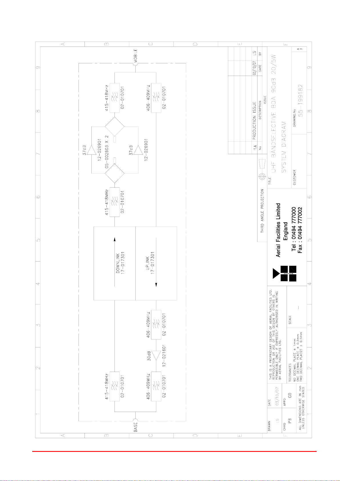
3.3. UHF Bandselective, BDA (55-199102) System Schematic
Drawing Number: 55-199182
UHF Bandselective BDA
90dB 40/5W
Document Number 55-199102HBKM Issue No. 1 Page 8 of 28
Page 9
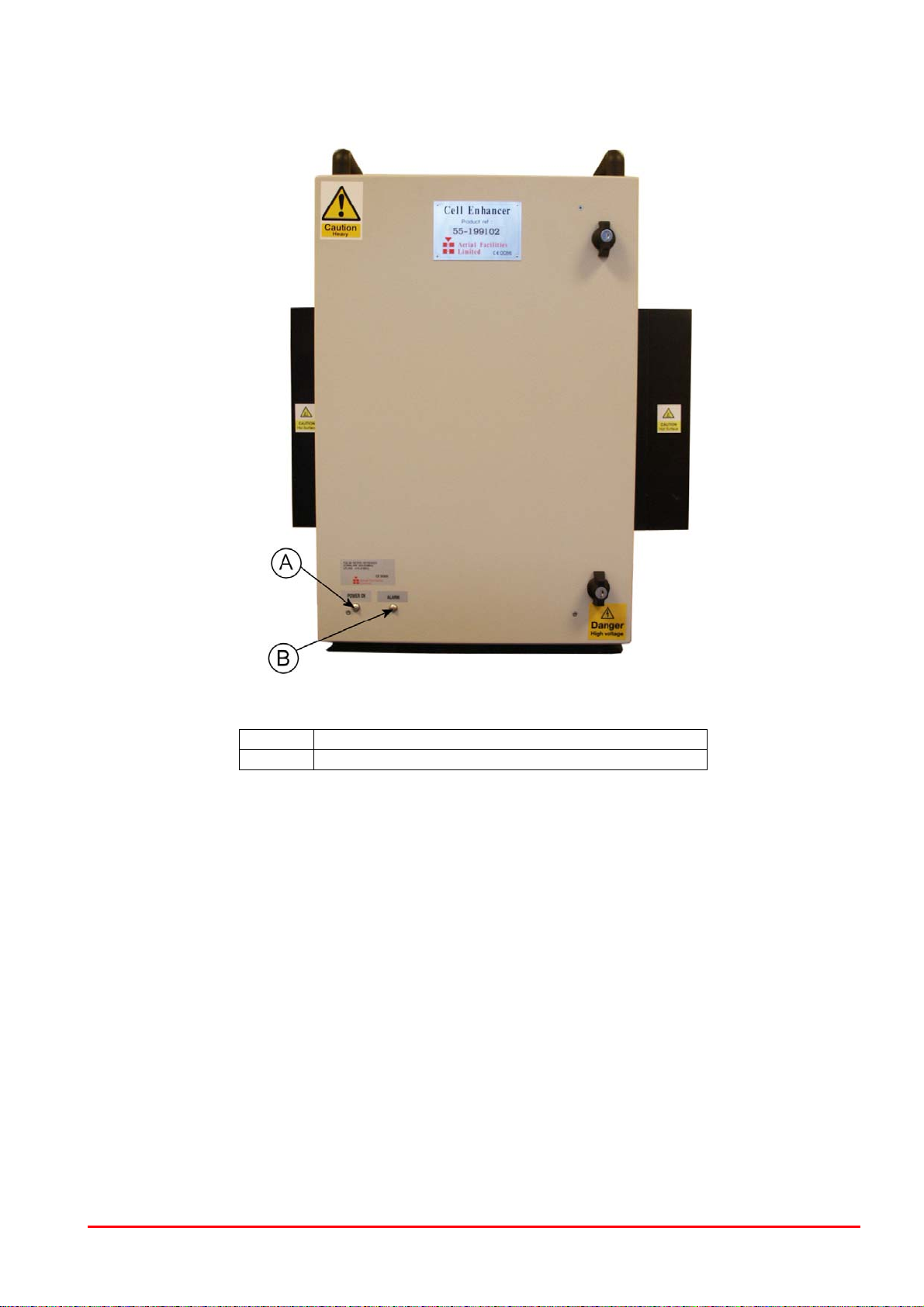
3.4. Photographs
3.4.1. Front of case – door closed
A Green LED “Power On”
B Red LED “Alarm”
UHF Bandselective BDA
90dB 40/5W
Document Number 55-199102HBKM Issue No. 1 Page 9 of 28
Page 10

3.4.2. Front of case – door open
A Bandpass Filters (02-010701)
B Bandpass Filters (02-010701)
C Linearised Power Amplifier (12-026901) (Downlink)
D 24V Switch-Mode PSU (96-300054)
E Bi-Directional Amplifier (17-017301)
F Linearised Power Amplifier (12-026901) (Downlink)
G 5 Watt Tetra Amplifier (12-021601) (Uplink)
H 3dB Splitter/Combiner (05-002603)
I 3dB Splitter/Combiner (05-002603)
J Voltage Regulators (13-001714)
K DC/DC convertor (13-003011)
L Attenuator control switches, Uplink top row – Downlink bottom row
M Mains On/Off switch
UHF Bandselective BDA
90dB 40/5W
Document Number 55-199102HBKM Issue No. 1 Page 10 of 28
Page 11

3.4.3. Right Hand and Left Hand sides
A Antenna Facing Mobile Port
B Alarm Output
C Earth Connection
D AC Input
E Antenna Facing Base Port
UHF Bandselective BDA
90dB 40/5W
Document Number 55-199102HBKM Issue No. 1 Page 11 of 28
Page 12

4. UHF BANDSELECTIVE, BDA (55-199102) SUB MODULES
4.1. Bandpass Filter (02-010701)
The bandpass filters are multi-section designs with a bandwidth dependent upon the passband
frequencies, (both tuned to customer requirements). The response shape is basically Chebyshev with
a passband design ripple of 0.1dB. The filters are of combline design, and are carefully aligned during
manufacture in order to optimise the insertion loss, VSWR and intermodulation characteristics of the
unit. The tuned elements are silver-plated to reduce surface ohmic losses and maintain a good VSWR
figure and 50 load at the input and output ports.
Being passive devices, the bandpass filters should have an extremely long operational life and require
no maintenance. Should a filter be suspect, it is usually most time efficient to replace the module
rather than attempt repair or re-tuning.
02-010701 Specification
PARAMETER SPECIFICATION
Response type: Chebyshev
Frequency range:
Bandwidth: 3 MHz
Number of sections: 5
Insertion loss: 1.7 dB (typical)
VSWR: better than 1.2:1
Connectors: SMA
Power Handling: 100W max
Temperature range
operation: -20°C to +60°C
storage: -40°C to +70°C
Weight: 3 kg (typical)
415 - 418MHz (uplink)
406 - 409MHz (downlink)
UHF Bandselective BDA
90dB 40/5W
Document Number 55-199102HBKM Issue No. 1 Page 12 of 28
Page 13

4.2. 3dB Splitter/Combiner (05-002603)
The 3dB Splitter/Combiner (05-002603) is a device for accurately matching two RF signals to a single
port or splitting an RF signal to two ports whilst maintaining an accurate 50 load to all inputs/outputs
and ensuring that the VSWR and insertion losses are kept to a minimum.
05-002603 Specification
PARAMETER SPECIFICATION
Frequency range: 380 - 520 MHz
Bandwidth: 140 MHz
Ports
Return Loss (VSWR) – Input: Better than 1.3:1
Return Loss (VSWR) – Output: Better than 1.3:1
Power Rating – Combiner: 0.5 Watt
Power Rating – Splitter: 20 Watts
As Combiner 2 inputs 1 output
As Splitter 1 input 2 outputs
Insertion loss: 3.5 dB (typical)
Isolation: >18 dB
Impedance: 50 Ω
Connectors: SMA female
Size: 54 x 44 x 21 mm
Weight: 200 gm (approximately)
4.3. Remote Attenuator Switch Assembly (‘10-001725’)
The remote attenuator switch assembly is used to control the amount of signal attenuation in the submodule, Bi-Directional Amplifier (17-017301). The switch assembly is mounted on the inside of the
Bandselective BDA (55-199102) case and consists of four miniature toggle switches, one row for
uplink and one row for downlink, built around the remote attenuator switch PCB (10-001725)
The switch assembly allows attenuation settings from 0 – 30dB in 2 dB steps The attenuation is
simply set using the four miniature toggle switches. Each switch is clearly marked with the attenuation
it provides, and the total attenuation in line is the sum of the values switched in. The attenuators that
the switches control are integral to sub-module Bi-Directional Amplifier (17-017301).
UHF Bandselective BDA
90dB 40/5W
Document Number 55-199102HBKM Issue No. 1 Page 13 of 28
Page 14

4.4. 5 Watt Tetra Amplifier (12-021601)
The power amplifier fitted to this unit is a multi-stage, solid state power amplifier. Class A circuitry is
employed throughout the device to ensure excellent linearity over a wide dynamic frequency range.
All the semi-conductor devices are very conservatively rated to ensure low device junction
temperatures and a long, trouble free working lifetime.
The power amplifier should require no maintenance over its operating life. Under no circumstances
should the cover be removed or the side adjustments disturbed unless it is certain that the amplifier
has failed; since it is critically aligned during manufacture and any re-alignment will require extensive
test equipment.
The unit housing is an aluminium case (Iridite NCP finish) with SMA connectors for the RF
input/output and a D-Type connector for the power supply and the Current Fault Alarm Function.
12-021601 Specification
PARAMETER SPECIFICATION
Frequency range: 380-470MHz (as required)
Bandwidth: 10-40MHz (typical, tuned to spec.)
Maximum RF output: >5Watts
Gain: >30dB
1dB compression point: +37.5dBm
3rd order intercept point: +50dBm
VSWR: better than 1.5:1
Connectors: SMA female
Supply: 1.9Amps @ 12V DC
Weight: 1kg (excluding heatsink)
operational:
range:
storage:
7-Way Connector Pin-out details
Connector Pin Signal
A1 (large pin) +10-24V DC
A2 (large pin) GND
1 Alarm relay common
2 TTL alarm/0V good
3 Alarm relay contact (bad)
4 Alarm relay contact (good)
5 O/C good/0V bad (TTL)
7-Way Pin-Out Graphical Representation
A1 A2
3 4 5
-10°C to +60°C Temperature
-20°C to +70°C
1 2
UHF Bandselective BDA
90dB 40/5W
Document Number 55-199102HBKM Issue No. 1 Page 14 of 28
Page 15

4.5. Linearised Power Amplifier (12-026901)
The power amplifier fitted to (this unit) is a multi-stage, solid state power amplifier. Class A circuitry is
employed throughout the device to ensure excellent linearity over a wide dynamic frequency range.
All the semi-conductor devices are very conservatively rated to ensure low device junction
temperatures and a long, trouble free working lifetime.
The power amplifier should require no maintenance over its operating life. Under no circumstances
should the cover be removed or the side adjustments disturbed unless it is certain that the amplifier
has failed; since it is critically aligned during manufacture and any re-alignment will require extensive
test equipment. The amplifier has a D-Type connector for the power supply and a Current Fault Alarm
Function.
12-026901 Specification
PARAMETER SPECIFICATION
Frequency range: 380-440MHz (tuned to spec.)
Bandwidth: <60MHz (typical)
Maximum RF output: >25Watt
Small signal gain: 37.5dB (typical)
1dB compression point: +44dBm
3rd order intercept point: +61dBm
Noise figure: N/A
Return input loss: >15dB
Return output loss: >15dB
VSWR: better than 1.5:1
RF Connectors: SMA female
Supply: 4.6Amps @ 24V DC
operation:
range:
storage:
Weight: 1.5 kg
12-026901 7-Way Connector Pin-outs
Connector Pin Signal
A1 (large pin) +24V DC
A2 (large pin) GND
1 Alarm relay common
2 TTL alarm/0V good
3 Alarm relay contact (bad)
4 Alarm relay contact (good)
5 O/C good/0V bad (TTL)
7-Way Connector Graphical Representation
A1 A2
3 4 5
-10°C to +60°C Temperature
-20°C to +70°C
1 2
UHF Bandselective BDA
90dB 40/5W
Document Number 55-199102HBKM Issue No. 1 Page 15 of 28
Page 16

4.6. Voltage Regulator Board 9.0V (13-001714)
This unit it is used to derive a fixed voltage power supply rail from some higher voltage. In this
instance it is used to derive 9V from a 12V input.
The circuit is based upon a fixed voltage regulator, which is capable of supplying a maximum of 2.0 A
output current. Note that at full output current the dissipation of the device must remain in limits,
bearing in mind the voltage which is being dropped across it. The maximum allowable dissipation will
also depend on the efficiency of the heatsink on which the device is mounted.
13-001714 Specification
PARAMETER SPECIFICATION
Operating voltage: 12V DC
Output voltages: 9.0V
Output current: 2.0A (maximum per o/p)
Connections: Screw Terminal Block
operational: -10°C to +60°C Temperature
range:
storage: -20°C to +70°C
PCB Size: 30.5 x 38.1mm
4.7. DC/DC Converter, 24V in, 12V 8A out (13-003011)
The DC/DC converter fitted is an AFL assembled, high power PCB unit with an 8 amp at 12V output
capability. The circuit is basically an O.E.M semiconductor regulator (one side of which has a heatsink
mounting plate, usually bolted to the casing of a Cell Enhancer) and smoothing components built onto
a printed circuit board with screw block terminations.
In event of failure this unit should not be repaired, only replaced.
13-003011 Specification
PARAMETER SPECIFICATION
Input Voltage range: 18-28V DC
Output voltage: 12V±0.5V
Max. current load: 8.0Amps
operation: -10°C to +60°C Temperature
range:
Size(PCB): 190 x 63mm
Weight (Loaded PCB): 291gms
storage: -20°C to +70°C
UHF Bandselective BDA
90dB 40/5W
Document Number 55-199102HBKM Issue No. 1 Page 16 of 28
Page 17

4.8. Bi-Directional Amplifier (17-017301)
This module is a Bi-Directional Amplifier (up-link and down-link). All the amplifier stages are of
balanced type and there is additionally digital attenuation, automatic level control (ALC) in the uplink
path and also Current Fault Alarm Function circuitry, which indicates failure of each RF transistor in
various ways – open collector, closed collector (TTL) and a relay to indicate the failure by voltage free
change over contacts.
The module is housed in an aluminium case (Iridite NCP finish) with SMA connectors for the RF
input/output and a D-type connector for power supply and Current Fault Alarm Function.
Specification 17-017301
PARAMETER SPECIFICATION
Frequency Range MHz 380-430
Gain 64 - 66 dB
Gain Flatness 2.0 dB
ΔGain vs. Temp.
ALC dynamic Range 28 dB Min
ALC o/p power level 29 ± 0.5 dBm Min
Input Return Loss 15 dB Min
Output Return Loss 18 dB Min
P1dB 30 dBm Min
OIP3 41 dBm Min
Noise Figure 1.7 dB Max
DC Supply 9.0V ± 0.5 at 1120 mA Max
Max RF Input +15dBm
Storage temperature -40 to +100 ºC
Operating temperature -20 to +70 ºC
Dimensions 291.0 x 165.6 x 28.5 mm
BDA ‘D’ Connector Pin-out details
Connector pin Signal
1 +ve input (9V)
2 +ve input (9V)
3 GND
4 GND
5 Alarm relay good
6 Alarm relay common
7 Alarm relay O/P bad
8 Attenuator In
9 Detector Out
10 Digital Attenuator Bit 1
11 Digital Attenuator Bit 2
12 Digital Attenuator Bit 3
13 Digital Attenuator Bit 4
14 Not Used
15 Not Used
2.5 dB Max
15-Way Pin-Out Graphical Representation
1 2 3 4 5 6 7 8
9 10 11 12 13 14 15
UHF Bandselective BDA
90dB 40/5W
Document Number 55-199102HBKM Issue No. 1 Page 17 of 28
Page 18

4.9. 12V (Single) Relay Board (80-008901)
The General Purpose Relay Board allows the inversion of signals and the isolation of circuits. It is
equipped with a single dual pole change-over relay RL1, with completely isolated wiring, accessed
via a 15 way in-line connector.
The relay is provided with polarity protection diodes and diodes for suppressing the transients caused
by "flywheel effect" which can destroy switching transistors or induce spikes on neighbouring circuits.
It’s common use is to amalgamate all the alarm signals into one, volts-free relay contact pair for the
main alarm system.
Specification 80-008901
PARAMETER SPECIFICATION
Operating voltage: 8 to 30V (floating earth)
Alarm threshold: Vcc - 1.20 volt +15%
Alarm output relay contacts:
Max. switch current: 1.0Amp
Max. switch volts: 120Vdc/60VA
Max. switch power: 24W/60VA
Min. switch load: 10.0µA/10.0mV
Relay isolation: 1.5kV
Mechanical life:
Relay approval: BT type 56
Connector details: Screw terminals
operational: -10°C to +60°C Temperature
range
storage: -20°C to +70°C
>2x10⁷ operations
4.10. 24V Switch-Mode PSU (96-300054)
The power supply unit is a switched-mode type capable of supplying 24V DC at 17.0Amps
continuously. Equipment of this type typically requires approximately 10.0 Amps at 24V DC, so the
PSU will be used conservatively ensuring a long operational lifetime.
No routine maintenance of the PSU is required. If a fault is suspected, then the output voltage from
the power supply may be measured on its output terminals. This is typically set to 24.5V using the
multi-turn potentiometer mounted close to the DC output studs on the PSU PCB.
All the PSUs used in AFL Cell Enhancers are capable of operation from either 110 or 220V nominal
AC supplies. The line voltage is sensed automatically, so no adjustment or link setting is needed by
the operator.
96-300054 Specification
AC Input Supply
Voltages:
Frequency: 47 to 63Hz
DC Output Supply:
Voltage:
Maximum current: 17A
110 or 220V nominal
90 to 132 or 180 to 264V (absolute limits)
24V DC (nominal)
20 to 28V (absolute limits)
UHF Bandselective BDA
90dB 40/5W
Document Number 55-199102HBKM Issue No. 1 Page 18 of 28
Page 19

5. INSTALLATION & COMMISIONING
5.1. Antenna Installation & Gain Calculations
1 Most Cell Enhancer require two antennas, one a highly directional Yagi or similar directed
towards the donor cell base station, and one a leaky feeder, omni-directional antenna or Yagi to cover
the area in which the mobiles are to be served.
2 The maximum gain at which the Cell Enhancer can be set is limited by the isolation that can
be achieved between these two antennas. Therefore when the antennas have been installed, inject a
signal (at a known power level) into one of them and measure the signal level received by the other
antenna on a spectrum analyser. The isolation can then be calculated as the difference between
these two figures. The gain in each path of the Cell Enhancer should be set at least 10 dB below this
figure, using attenuators as described below in paragraph 5.
3 Also measure the received signal from the donor cell at the input to the Cell Enhancer (base
port). The gain of the Cell Enhancer downlink path should be set such the donor site will not overload
the Cell Enhancer amplifiers. It is recommended that the input level should be less than -50dBm at
the input of the Cell Enhancer (Base Port). (This figure is assuming maximum gain, and may be
increased by the value of the attenuator fitted in the downlink path.)
4 Ensure that the mobile facing antenna has at least 70 dB isolation from the nearest mobile.
(This is usually easily achieved when using a leaky feeder.)
5 The Cell Enhancer gain is set by setting the attenuation in each path (uplink and downlink)
between the first two amplifier stages (see markings within the Cell Enhancer or layout drawings for
the exact attenuator locations). Note that the uplink (mobile to base) and downlink (base to mobile)
path gains are set independently. This allows the paths to have different gains if required to set the
correct output power levels.
6 It is recommended that the gains are set such that the Downlink output levels from the Cell
Enhancer are typically +44dBm. (Input level + Gain = Output level).
5.2. Initial Installation Record
When this equipment is initially commissioned, please use the equipment set-up record sheet in
Appendix B This will help both the installation personnel and AFL should these figures be needed for
future reference or diagnosis.
UHF Bandselective BDA
90dB 40/5W
Document Number 55-199102HBKM Issue No. 1 Page 19 of 28
Page 20

6. FAULT FINDING / MAINTENANCE
6.1. Tools & Test Equipment
The minimum tools and test equipment needed to successfully service this AFL product are as
follows:-
Spectrum analyser: 100kHz to 2GHz (Dynamic range = 90dB).
Signal Generator: 30MHz to 2GHz (-120dBm to 0dBm o/p level).
Attenuator: 20dB, 10W, DC-2GHz, (N male – N female).
Test Antenna: Yagi or dipole for operating frequency.
Digital multi-meter: Universal Volt-Ohm-Amp meter.
Test cable x 2: N male – N male, 2M long RG214.
Test cable x 2: SMA male – N male, 1m long RG223.
Hand tools: Philips #1&2 tip screwdriver.
3mm flat bladed screwdriver.
SMA spanner and torque setter.
6.2. Basic Fault Finding
In the event that the performance of the system is suspect, a methodical and logical approach to the
problem will reveal the cause of the difficulty. The System consists of modules in a wall-mounted
enclosure.
Transmissions from the main base stations are passed though the system to the mobile radio
equipment; this could be a handheld radio or a transceiver in a vehicle. This path is referred to as the
downlink. The return signal path from mobile radio equipment to the base station is referred to as the
uplink.
The first fault finding operation is to check the alarms of each of the active units and determine that
the power supplies to the equipment are connected and active. This can be achieved remotely (via
CEMS, the RS232
panel LEDs. The green LED on the front panel should be illuminated, while the red alarm indicator
should be off. Note that passive only shelves will have no DC power or alarm indicators. If an Alarm is
on, then that individual shelf must be isolated and individually tested against the original test
specification. The individual amplifier units within any shelf have a green LED showing through a hole
in their cover, which is illuminated if the unit is working correctly. (Without active power supplies there
can be no alarm LED indicators, however without DC power, the fail-safe summary alarm system
[normally closed relay contacts] will be an open circuit, thereby activating any externally connected
system.)
If an amplifier is suspect, check the DC power supply to the unit. If no other fault is apparent use a
spectrum analyser to measure the incoming signal level at the input and then after reconnecting the
amplifier input, measure the output level. Consult with the system diagram to determine the expected
gain and compare result.
In the event that there are no alarms on and all units appear to be functioning it will be necessary to
test the system in a systematic manner to confirm correct operation.
Coverage Enhancement Management System, if fitted), or locally with the front
UHF Bandselective BDA
90dB 40/5W
Document Number 55-199102HBKM Issue No. 1 Page 20 of 28
Page 21

6.3. Quick Fault Checklist
All AFL equipment is individually tested to specification prior to despatch. Failure of this type of
equipment is not common. Experience has shown that a large number of fault conditions relating to
installations result from simple causes often occurring as result of transportation, unpacking and
installation. Below are listed some common problems which have resulted in poor performance or an
indicated non-functioning of the equipment.
Mains power not connected or not switched on.
External connectors not fitted or incorrectly fitted.
Internal connectors/ports becoming loose due to transport vibration.
Wiring becoming detached as a result of heavy handling.
Input signals not present due to faults in the aerial or feeder system.
Base transmissions not present due to faults at the base station.
Modems fitted with incorrect software configuration/and or PIN Nos.
Changes to channel frequencies and inhibiting channels.
Hand held radio equipment not correctly set to repeater channels.
Hand held radio equipment not correctly configured to base station.
6.4. Downlink
C
onfirm that there is a signal at the expected frequency and strength from the base station(s). If this is
not present then the fault may lay outside the system. To confirm this, inject a downlink frequency
signal from a known source at the BTS input and check for output at the antenna output port.
If a signal is not received at the output it will be necessary to follow the downlink path through the
system to find a point at which the signal is lost.
6.5. Uplink
T
esting etc. of the uplink paths is similar to the downlink paths, except for the frequencies involved.
6.6. Fault repair
O
nce a faulty component has been identified, a decision must be made on the appropriate course to
carry out a repair. A competent engineer can quickly remedy typical faults such as faulty connections
or cables. The exceptions to this are cable assemblies connecting bandpass filter assemblies
(duplexers) that are manufactured to critical lengths to maintain a 50-ohm system.
Care should be taken when replacing cables or connectors to ensure that items are of the correct
specification. The repair of component modules such as amplifiers and bandpass filters will not
usually be possible in the field, as they frequently require specialist knowledge and test equipment to
ensure correct operation. It is recommended that items of this type are replaced with a spare unit and
the faulty unit returned to AFL for repair.
Following the repair of any part of the system it is recommended that a full end-to-end test is carried
out in accordance with the test specification and that the coverage is checked by survey.
It is important to bear in mind that the system includes antennas and base stations that m
or may have been damaged.
ay be faulty
6.7. Service Support
A
dvice and assistance with maintaining and servicing this system are available by contacting Aerial
Facilities Ltd. see section 2.7.
UHF Bandselective BDA
90dB 40/5W
Document Number 55-199102HBKM Issue No. 1 Page 21 of 28
Page 22

6.8. Care of Modules
Many of the active modules contain semiconductor devices utilising MOS technology, which can be
damaged by electrostatic discharge. Correct handling of such modules is mandatory to ensure their
long-term reliability. Good engineering practices should be observed at all times.
To prevent damage to a module, it must be withdrawn/inserted with care.
6.9. Module Removal (LNAs, general procedure):
The following general rules should be followed to remove a module:
1) Remove power to the unit
2) Remove all connectors (RF, DC/alarm)
3) Release module retaining screws.
4) Slowly but firmly, pull the module straight out of its position. Take care not to twist/turn the
module during withdrawal.
6.10. Module Replacement (general):
1) Carefully align the module into its location then slowly push the module directly straight into its
position, taking care not to twist/turn it during insertion.
2) Reconnect all connectors, RF, alarm, power etc.
3) Replace retaining screws (if any).
4) Double-check all connections before applying power.
6.11. Power Amplifiers
1) Remove power to the unit. (Switch off at mains/battery)
2) Disconnect multi-way alarm ‘D’ type connector
3) Carefully disconnect the RF input and output coaxial connectors (usually SMA)
4) If the amplifier to be removed has a heatsink attached, there may be several different ways it
can have been assembled. The most commonly used method, is screws through the front of the
heatsink to threaded screw holes (or nuts and bolts), into the amplifier within the main case. If the
heatsink is mounted on the rear of the main case (e.g., against a wall in the case of wall mounted
enclosures), then the fixing method for the heatsink will be from within the case, (otherwise the
enclosure would have to be removed from the wall in order to remove the heatsink).
When the heatsink has been removed, the amplifier may be unscrewed from the main casing by its
four corner fixings and gently withdrawn.
Fitting a new power amplifier module will be the exact reverse of the above.
Note: Do not forget to apply fresh heatsink compound to the heatsink/main case joint and
also between the amplifier and the main case.
UHF Bandselective BDA
90dB 40/5W
Document Number 55-199102HBKM Issue No. 1 Page 22 of 28
Page 23

5) If the amplifier to be removed has a heatsink attached, there may be several different ways it
can have been assembled. The most commonly used method, is screws through the front of the
heatsink to threaded screw holes (or nuts and bolts), into the amplifier within the main case. If the
heatsink is mounted on the rear of the main case (e.g., against a wall in the case of wall mounted
enclosures), then the fixing method for the heatsink will be from within the case, (otherwise the
enclosure would have to be removed from the wall in order to remove the heatsink).
When the heatsink has been removed, the amplifier may be unscrewed from the main casing by its
four corner fixings and gently withdrawn.
Fitting a new power amplifier module will be the exact reverse of the above.
Note: Do not forget to apply fresh heatsink compound to the heatsink/main case joint and also
between the amplifier and the main case.
6.12. Low Power Amplifier Replacement
Disconnect the mains power supply and disconnect the 24V dc supply connector for the LPA.
Disconnect the RF input and output cables from the LPA.
Disconnect the alarm connector.
Remove the alarm monitoring wires from (D type connector) pins 9 and 10.
Remove the LPA module by removing the four retaining screws, replace with a new LPA module and
secure it with the screws.
Connect the RF cables to the LPA input and output connectors. Reconnect the wires to the alarm
board connector pins 9 and 10.
Reconnect the DC supply connector and turn the mains switch on.
Note: Tighten SMA connectors using only a dedicated SMA torque spanner. If SMA connectors are
over-tightened, irreparable damage will occur. .
connectors.
Also take care not to drop or knock the module as this can damage (or misalign in the case of tuned
passive modules) sensitive internal components. Always store the modules in an environmentally
friendly location
Test equipment should always be used to verify the performance of any new module fitted to
the system before broadcasting in the public domain.
Do not use adjustable pliers to loosen/tighten SMA
6.13. Module Transportation:
To maintain the operation, performance and reliability of any module it must be stored and
transported correctly. Any module not installed in a whole system must be kept in an anti-static bag or
container. Any module sent back to AFL for investigation/repair must be so protected. Please contact
AFL’s quality department before returning a module, see section 2.7.
UHF Bandselective BDA
90dB 40/5W
Document Number 55-199102HBKM Issue No. 1 Page 23 of 28
Page 24

APPENDIX A
A.1. Glossary of Terms used in this document
Repeater or
Cell Enhancer
Band Selective
Repeater
Channel Selective
Repeater
AC Alternating Current
AGC Automatic Gain Control
BBU Battery Backup Unit
BTS Base Transceiver Station
CEMS Coverage Enhanced Management System
C/NR Carrier-to-Noise Ratio
DC Direct Current
Downlink (D/L) RF signals TX from the BTS to the Master Site
FO Fibre Optic
GND Ground
ID Identification Number
LED Light Emitting Diode
LNA Low Noise Amplifier
LPA Low Power Amplifier
MOU Master Optical Unit
M.S. Mobile Station
MTBF Mean Time Between Failures
N/A Not Applicable
N/C No Connection
OFR On Frequency Repeater
OIP3 Output Third Order Intercept Point
P1dB 1dB Compression Point
PA Power Amplifier
RF Radio Frequency
RSA Receiver/Splitter Amplifier
RX Receiver
S/N Serial Number
TX Transmitter
Uplink (U/L) RF signals transmitted from the MS to the BTS
VSWR Voltage Standing Wave Ratio
WDM Wave division multiplex
A Radio Frequency (RF) amplifier which can simultaneously
amplify and re-broadcast Mobile Station (MS) and Base
Transceiver Station (BTS) signals.
A Cell Enhancer designed for operation on a range of channels
within a specified frequency band.
A Cell Enhancer, designed for operation on specified channel(s)
within a specified frequency band. Channel frequencies may be
factory set or on-site programmable.
UHF Bandselective BDA
90dB 40/5W
Document Number 55-199102HBKM Issue No. 1 Page 24 of 28
Page 25

A.2. Key to Drawing Symbols used in this document
A
89
ANTENNAS
OMNI ANTENNA
YAGI ANTENNA
FLAT PLATE ANTENNA
(MOUNTED AT HIGH LEVEL)
DIRECTIONAL ANTENNA
ANTENNA
REMOTE ANTENNA UNIT
RAU
SPLITTERS
HYBRID SPLITTER
OUT
OUT
IN
CABLES
8/FIBRE OPTIC CABLE /LINK
4 6
CABLE 1/2"
RADIATING CABLE
1/2" DIA
C0-AX CABLE
CAT 5 CABLE
JUMPER
24/FIBRE OPTIC C ABLE/LINK
J
3 5 7
COUPLERS
6 dB DIRECTIONAL COUPLER
10dB COUPLER
10dB DIRECTIONA L COUPLER
DIRECTIONAL COUPLER
6dB DIRECTIONAL COUPLER
C10
C6
OUTIN
C10
COUPLED
2
HUBS
FIBRE MAIN HUB
1
FMH
TAPPER/COUPLER
EXPANSION HUB
E
EH
A
B
Outputs
C0-AX CABLE
CROSS BAND COUPLER
HI COM
B
C
STANDARD EXCEPT
LEVEL (dBm)
IDENTITY CODE)
BSIC (BASIC SITE
BCCH (BROADCAST
= READING POSITION
CONTROL CHANNEL)
22 =
602 =
AC TO DC PSU
-82 = ACCEPTABLE SIGNAL
DC TO DC
CONVERTER
DC
PANEL ANTENNA
SPLITTER
(up to
16 way)
SIGNAL KEY
BLADE ANTENNA
MISC
DC
MISC
AMPLIFIER
7/8" DIA
MISC
LOW
MISC
ATTENUATOR (VARIAB LE)
dB
BAND PASS FILTER
CAVITY RESONATOR
STATION
BASE TRANSCEIVER
B/W=30 to 200kHz
BTS
CHANNEL MODULE
A.G.C
ATTENUATOR (FI XED)
dB
AGC dB
NOTCH FILTER
ISOLATOR
IN
FIBRE-OPTIC
MODULATOR
FREQUENCY PROGRAMMING
RF
DATA
C
D
FOR AIRPORTS
(SEE BELOW)
SIGNAL LEVEL(dBm)
-83 = BELOW ACCEPTABLE
FUSE
MONITORING CONTROLLER
MONITORING
CONTROLLER
HYBRID COMBINER
OUT
IN
FIBRE-OPTIC
DEMODULATOR
RF
D
-72 = ACCEPTABLE SIGNAL
STANDARD FOR
N.O. (CLEAR CONTACT)
MODEM
EARTH STUD
PL
E
BYDATEDESCRIPTIONNo
PL
PLBLADE ANTENNA ADDED1A
PL
F
3
A
9
23/05/00
21/06/00
26/01/04
28/07/04
ALL AIRPORTS
ISSUE
90-000001
8
LEVEL (dBm)
SIGNAL LEVEL(dBm)
-73 = BELOW ACCEPTABLE
2B TEXT CORRECTION
2A ECN3165
ORIGINAL
ISSUE
AA
7
AFL - STANDARD SYMBOLS
TITLE
RELAY
N.C. (FILLED CONTACT)
COM
THIRD ANGLE PROJECTION
(CELL ENHANCER)
DUMMY LOAD
BI-DIRECTIONAL AMPLIFIER
MODEM
LOCAL OSCILLATOR
LOCAL OSCILLATOR
CUSTOMER DRAWING.No
England
Aerial Facilities Limited
56
Tel : 01494 777000
Fax : 01494 777002
4
NTS
LEEKY FEEDER
R.S.A
Outputs to receivers
SCALE
23
THIS IS A PROPRIETARY DESIGN OF AERIAL FACILITIES LTD.
REPRODUCTION OR USE OF THI S DESIGN BY OTHERS IS
PERMISSIBLE ONLY IF EXPRESSLY AUTHORISED IN WRITING
BY AERIAL FACILITIES LTD.
NO DECIMAL PLACE ± 1mm
ONE DECIMAL PLACE ± 0.3mm
TWO DECIMAL PLACES ± 0.1mm
FIBRE OPTIC
CONNECTOR
SOCKET
PLUG & SOCKET
FC/APC
PLUG
DATE
TOLERANCES
10/05/00
APPD
1
PL
MB GD
ALL DIMENSIONS ARE IN mm
CHKD
DRAWN
E
UNLESS OTHERWISE STATED
F
UHF Bandselective BDA
90dB 40/5W
Document Number 55-199102HBKM Issue No. 1 Page 25 of 28
Page 26

A.3. EC Declaration of Conformity
In accordance with BS EN ISO/IEC 17050-1&-2:2004
Aerial Facilities Limited
Aerial House
Asheridge Road
Chesham
Buckinghamshire HP5 2QD
United Kingdom
DECLARES, UNDER OUR SOLE RESPONSIBILITY THAT THE FOLLOWING PRODUCT:
PRODUCT PART NO[S] 55-199102
PRODUCT DESCRIPTION UHF Bandselective Bi-Directional Amplifier
IN ACCORDANCE WITH THE FOLLOWING DIRECTIVES:
1999/5/EC The Radio & Telecommunications Terminal Equipment Directive Annex V
and its amending directives
HAS BEEN DESIGNED AND MANUFACTURED TO THE FOLLOWING STANDARD[S] OR
OTHER NORMATIVE DOCUMENT[S]:
BS EN 60950 Information technology equipment.
Safety. General requirements
ETS EN 301 489-1 EMC standard for radio equipment and services.
Part 1. Common technical requirements
I hereby declare that the equipment named above has been designed to comply with the relevant
sections of the above referenced specifications. The unit complies with all essential requirements
of the Directives.
SIGNED
B S BARTON
TECHNICAL DIRECTOR DATE: 01/10/2007
Registered Office: Aerial House, Asheridge Road, Chesham, Buckinghamshire, HP5 2QD England Registered No. 4042808 (England)
Aerial Facilities Limited
www.aerialfacilities.com
UHF Bandselective BDA
90dB 40/5W
Document Number 55-199102HBKM Issue No. 1 Page 26 of 28
Page 27

A.4. Amendment List Record Sheet
Issue
No.
A 26/09/2007 AJS Draft
1 05/10/2007 AJS First Issue
Document Ref. 55-199102HBKM
Date Incorporated
by
Page Nos.
Amended
Reason for new issue
UHF Bandselective BDA
90dB 40/5W
Document Number 55-199102HBKM Issue No. 1 Page 27 of 28
Page 28

APPENDIX B
Initial Equipment Set-Up Calculations
General Information
Site Name:
Date:
Antenna Systems
Model Gain Azimuth Comments
A - Service Antenna
B – Donor Antenna
Type Loss Length Comments
C – Service Feeder
D – Donor Feeder
Initial Parameters
E – CE Output Power dBm
F – Antenna Isolation dB
G – Input signal level from donor BTS dBm
Operating Voltage V
Downlink Calculations
Parameter Comments Value
Input signal level (G) dBm
CE max. o/p power (E) dBm
Gain setting E - G dB
Isolation required (Gain + 10dB) dB
Service antenna gain (A) dB
Service antenna feeder loss (C) dB
Effective radiated power (ERP) E+A-C dBm
Attenuator setting CE gain-gain setting dB
If the input signal level in the uplink path is known and steady, use the following calculation table to
determine the gain setting. If the CE features Automatic Gain Control the attenuator should be set to
zero and if not, then the attenuation setting for both uplink and downlink should be similar.
Uplink Calculations
Parameter Comments Value
Input signal level dBm
CE max. o/p power (E) dBm
Gain setting dB
Required isolation dB
Donor antenna gain (B) dB
Donor antenna feeder loss (D) dB
Effective radiated power (ERP) E+B-D dBm
Attenuator setting (CE gain-gain setting) dB
Client Name:
AFL Equip. Model No.
UHF Bandselective BDA
90dB 40/5W
Document Number 55-199102HBKM Issue No. 1 Page 28 of 28
 Loading...