


ActiveTagTM System
Installation Manual

Notices
2 750.001.004 R0033 © 2001 AXCESS Inc.

Notices
FCC Rules
Notices
Information provided in this manual is a result of the design and
development of AXCESS Inc. products and is subject to change
without notice. It applies only to current AXCESS Inc. RFID systems.
No part of this manual may be reproduced, translated or transmitted,
in any form or by any means, without the prior written consent of
AXCESS Inc.
Note:
This equipment has been tested and found to com ply with the
limits for a Class B digital device, pursuant to Part 15 of the FCC
Rules. These limits are designed to provide reasonable protection
against harmful interference in a residential installation. This
equipment generates, uses, and can r adiate radio frequency energy
and, if not installed and used in accordance with the instructions, may
cause harmful interference to radio comm unic ations . However, there
is no guarantee that interference will not occur in a particular
installation. If this equipment does cause harmful interference to
radio or television reception, which can be determined by turning the
equipment off and on, the user is encouraged to try to correct the
interference by one or more of the following measures:
• Reorient or relocate the receiving antenna
• Increase the separation between the equipment and receiver
• Connect the equipment into an outlet on a circuit different from
• Consult the dealer or an experienced radio/TV technician for help
Responsibilities
• AXCESS Inc. declines all liability for any damage that might
• AXCESS Inc. can only guarantee the correct operation of its
• AXCESS Inc. recommends keeping the original packaging for
Registered Trademarks
Product names mentioned herein may be trademarks and/or
registered trademarks of their respective companies.
that to which the receiver is connected
result from any errors or omissions in this document or from
improper installation.
products if they are used with the software programs, systems,
and consumables supplied or authorized in writing by AXCESS
Inc.
transporting the equipment later.
© 2001, AXCESS Inc. 750.001.004 R0033 3

Notices
Customer Service
U.S. Patents
AXCESS Inc. toll-free support line is 1-800-577-6080.
Representatives are available from 7:30 – 6:30 Central Time.
4,816,901 4,843,466 4,847,677
4,849,807 4,857,991 4,857,993
4,914,508 5,140,412 6,034,603
Other patents pending.
4 750.001.004 R0033 © 2001 AXCESS Inc.

Table of Contents
GENERAL INSTALLATION INFORMATION ...........................................................................9
AFETY
S
NFORMATION FLAGS
I
H
ACTIVETAG SYSTEM OVERVIEW........................................................................................13
A
T
A
R
T
SYSTEM CONFIGURATION BASICS....................................................................................19
...................................................................................................................................9
................................................................................................................9
AND TOOLS
QUIPMENT AND MATERIALS
, E
.............................................................................10
Required...........................................................................................................................10
Recommended................................................................................................................. 11
CTIVETAG SYSTEM COMPONENTS
AGS
.....................................................................................................................................14
CTIVATOR
ECEIVER
............................................................................................................................14
..............................................................................................................................15
........................................................................................13
Filters................................................................................................................................16
Serial Output ....................................................................................................................16
Wiegand Output ...............................................................................................................16
IP Output..........................................................................................................................16
RANSMIT ANTENNAS
.............................................................................................................16
Types of Transmit Antennas ............................................................................................16
NTRODUCTION
I
PPLICATION TYPES
A
.......................................................................................................................19
..............................................................................................................19
Vehicle..............................................................................................................................19
Personnel and/or Asset....................................................................................................20
ULTIPLE ACTIVATOR APPLICATIONS
M
NSTALLATION TIPS
I
................................................................................................................21
......................................................................................21
Waterproofing...................................................................................................................21
Checking Activation Fields ...............................................................................................22
Cable Length for Antennas............................................................................................... 22
ASIC INSTALLATION STEPS
B
...................................................................................................23
CONFIGURING AND INSTALLING THE ACTIVATOR..........................................................25
NTRODUCTION
I
.......................................................................................................................25
Activator IDs.....................................................................................................................25
UPPLYING POWER
S
ETTING THE ACTIVATOR
S
................................................................................................................26
ID................................................................................................... 26
Method 1: Serial Commands............................................................................................26
Method 2: Hardware.........................................................................................................28
THER SERIAL PORT COMMANDS
O
...........................................................................................30
Receiving Help .................................................................................................................30
Changing the Baud Rate..................................................................................................30
Tuning the Activation Field...............................................................................................30
CTIVATOR INSTALLATION
A
......................................................................................................31
Required Materials ........................................................................................................... 31
Mounting the Activator...................................................................................................... 31
ESIZING THE ACTIVATION FIELD
R
............................................................................................32
Adjusting the Field............................................................................................................32
CONFIGURING THE RECEIVER ........................................................................................... 33
NTRODUCTION
I
ONNECTING POWER TO THE RECEIVER
C
.......................................................................................................................33
.................................................................................33
© 2001, AXCESS Inc. 750.001.004 R0033 5

Contents
ONFIGURING THE RECEIVER
C
..................................................................................................34
Receiver Defaults..............................................................................................................34
Required Materials............................................................................................................34
Connecting a Computer to the Receiver...........................................................................34
Communicating via HyperTerminal...................................................................................35
ECEIVER RESPONSES
R
ETTING UP A WIEGAND SYSTEM
S
...........................................................................................................35
............................................................................................36
Responding to Activator IDs .............................................................................................36
Alarm Output.....................................................................................................................36
ETTING UP A SERIAL OR
S
LAN S
YSTEM
...................................................................................36
Setting the Baud Rate.......................................................................................................36
Serial Output.....................................................................................................................36
Optimizing Serial Output...................................................................................................37
To restore TTL output operations, type: ...........................................................................37
20c...................................................................................................................................37
ETTING THE RECEIVER
S
NABLING
E
IAGNOSTIC MODE
D
TTL
OUTPUTS (LOGIC CONTROL
ID.....................................................................................................39
)............................................................................39
.................................................................................................................40
Turning off Diagnostic Mode.............................................................................................41
IEWING CONFIGURATION SETTINGS
V
.......................................................................................41
CONFIGURING THE NIU........................................................................................................43
NTRODUCTION
I
ONNECTING THE
C
ETTING UP THE SERIAL PORT
S
ONNECTING THE RECEIVER AND THE
C
ODIFYING THE
M
.......................................................................................................................43
TO THE
NIU
PC ..........................................................................................43
................................................................................................45
NIU..............................................................................46
ONFIGURATION
NIU C
.....................................................................................46
INSTALLING THE RECEIVER................................................................................................47
ONNECTING TO A WIEGAND CONTROL PANEL
C
........................................................................47
Wiegand Output................................................................................................................48
ONNECTING TO A SERIAL DEVICE
C
..........................................................................................48
Serial Output.....................................................................................................................49
IRING
W
ONNECTING TO THE
C
OUNTING THE RECEIVER
M
TTL O
UTPUTS TO
NIU
OUTPUTS
TTL
AND THE NETWORK
................................................................................49
.........................................................................51
......................................................................................................52
Mounting the Receiving Antenna Separately....................................................................53
ROAD LOOP ANTENNA INSTALLATION..............................................................................55
NTRODUCTION
I
EQUIRED MATERIALS
R
REREQUISITE TASKS
P
OAD LOOP LAYOUT
R
NSTALLING THE ROAD LOOP ANTENNA (FREQUENTLY CONTRACTED
I
.......................................................................................................................55
............................................................................................................56
.............................................................................................................56
ONNECTING TO THE ACTIVATOR
& C
.........................................................56
) .......................................59
BAR ANTENNA INSTALLATION............................................................................................61
NTRODUCTION
I
REREQUISITE TASKS
P
NSTALLATION CONSIDERATIONS
I
NSTALLING THE BAR ANTENNA
I
.......................................................................................................................61
.............................................................................................................61
.............................................................................................61
...............................................................................................63
PICTURE FRAME ANTENNA INSTALLATION......................................................................65
NTRODUCTION
I
REREQUISITE TASKS
P
.......................................................................................................................65
.............................................................................................................65
6 750.001.004 R0033 © 2001 AXCESS Inc.

Contents
NSTALLING THE PICTURE FRAME ANTENNA
I
.............................................................................65
TAGS....................................................................................................................................... 67
YPES OF TAGS
T
.....................................................................................................................67
LED Test Tag...................................................................................................................67
Personnel Tag..................................................................................................................67
Personnel Tag with Panic Alarm ......................................................................................67
Asset Tag.........................................................................................................................67
Asset Tag with Tamper Detect......................................................................................... 67
Vehicle Tag ......................................................................................................................67
Clicker Tag.......................................................................................................................67
Harsh Environment Vehicle Tag.......................................................................................67
Metal Mount Equipment Tag ............................................................................................ 68
AG LABELING
T
HE
LED T
T
OUNTING TAGS TO ASSETS
M
.......................................................................................................................68
EST TAG
...............................................................................................................69
..................................................................................................69
Required Materials ........................................................................................................... 69
Testing Mounting Positions .............................................................................................. 70
Mounting the Asset Tag with Adhesive ............................................................................ 70
Mounting a Tamper Tag................................................................................................... 71
OUNTING TAGS TO VEHICLES
M
...............................................................................................71
Required Materials ........................................................................................................... 71
Mounting locations............................................................................................................71
Testing for the Best Tag Location ....................................................................................71
Mounting a Vehicle Tag.................................................................................................... 72
AGS AND PERSONNEL
T
...........................................................................................................73
Required Materials ........................................................................................................... 73
Operating Panic Tags....................................................................................................... 73
APPENDIX A: TROUBLESHOOTING THE SYSTEM............................................................75
Road Loop........................................................................................................................76
Bar and Picture Frame Antennas.....................................................................................76
Serial ................................................................................................................................77
Wiegand...........................................................................................................................77
APPENDIX B: COAX IAL CABLE ........................................................................................... 79
APPENDIX C: ADVANCED WIEGAND CONFIGURATION................................................... 81
Setting the Time between Outputs...................................................................................81
Changing the Duplicate Tag Buffer .................................................................................. 81
APPENDIX D: RECEIVER COMMANDS................................................................................83
APPENDIX E: SPECIFICATIONS...........................................................................................87
Dimensions.......................................................................................................................87
Connectors.......................................................................................................................87
Power...............................................................................................................................87
Dimensions.......................................................................................................................87
Connectors.......................................................................................................................87
Power...............................................................................................................................88
Road Loop Antenna .........................................................................................................88
Bar Antenna .....................................................................................................................88
Picture Frame Antenna .................................................................................................... 89
© 2001, AXCESS Inc. 750.001.004 R0033 7

Contents
Personnel Tag / Personnel Tag with Panic Alarm / Vehicle Tag / Asset Tag / Asset Tag
with Tamper Detect...........................................................................................................89
Harsh Environment Vehicle Tag.......................................................................................89
Metal Mount Equipment Tag.............................................................................................90
INDEX ......................................................................................................................................91
8 750.001.004 R0033 © 2001 AXCESS Inc.

General Installation Information
Safety
• Personal safety is of first importance in the performance of any
job.
• Installation and configuration of the ActiveTag system should
only be performed by experienced installers.
• Where practical or required by code, all wiring should be
enclosed in conduit, or equivalent protection, firmly anchored to
sturdy structural elements and protected from mechanical
damage.
• Hand tools should be of good quality and properly maintained.
• Hand tools should be used in the applications for which they were
intended.
• Always wear eye protection when using power tools.
• When drilling, cutting or drilling, do not damage wires, pipes or
structural components.
• When installing antennas and related equipment above a ceiling,
make sure they are properly attached to a structural member and
accessible for maintenance.
Information Flags
Information flags in this document draw your attention to important
information:
IMPORTANT!
These sections provide information you must have to ensure proper
operation of hardware or software. If this advice is not followed,
system recovery can be difficult or time-consuming. ALWAYS READ
THESE ITEMS.
NOTE
These sections provide helpful information that can make the
installation go more smoothly and quickly.
© 2001, AXCESS Inc. 750.001.004 R0033 9

General Installation Information
Hand Tools, Equipment and Materials
IMPORTANT!
ensure successful installation of the ActiveTag system.
You need to have the following materials on hand to
These items are
Required
• RG-58/U coaxial cable with 50-ohm impedance (nominal), solid
copper center conductor, 55% tinned copper braid or better,
100% foil shield coverage (for example, Belden 9310). Finished
length should be no more than 25 feet. If installed outside, the
cable should be rated for direct burial.
• 3-piece crimp type male BNC connectors (for example,
Amphenol 31-320). Connectors can be damaged during
crimping. Having more than two on hand for each cable made is
recommended.
• A computer or terminal device to configure the Activator and
Receiver
• A terminal communication program such as HyperTerminal
(standard with MS Windows installations)
• A straight-through (one-to-one) DB9 male to female serial cable.
DO NOT use a null-modem cable or a null-modem adapter.
• Tape measure
• Power drill and bits
not
supplied with the ActiveTag System.
• Phillips and flathead screwdrivers, including a very small flathead
screwdriver
• Needle-nose pliers
• Diagonal cutters
• Wire strippers
• Three blade rotary coaxial cable stripper
• BNC crimpers
• Multimeter
Required for Road Loop Antenna Installation (typically contracted)
• Saw for cutting the road surface (e.g., a walk-behind concrete
saw)
• Two 1/8” saw blades with spacer – abrasive blades for asphalt or
diamond blades for concrete
• Vacuum or compressed air to clean the cut
10 750.001.004 R0033 © 2001 AXCESS Inc.

General Installation Information
• Mounting or burying hardware – concrete nails, thin dowel for
pushing wire into cut, etc.
• Road Sealant – For example, Bondo Flexible Embedding Sealer
(P-606), 3M Detector Loop Sealant or Q-Seal sealant. It takes
about a gallon of “Bondo” to seal the cuts for a 4x16-foot
antenna.
Required for Wiegand Output
• Receiver Wiegand output is standard SIA 26-bit. The Receiver
outputs
Receiver and the Wiegand control panel should be 18 AWG and
no longer than 500 feet. The wires should be green for Data
Zero, white for Data One, black for Common Ground and red for
5 VDC.
Required for Serial Output
• A straight-through (one to one) RS-232 cable of sufficient length
to connect the Receiver to the system PC. It is recommended
that the cable not exceed 50 feet in length. One end of the cable
should be a male DB9 connector.
Data Zero, Data One
and
Ground
. Wires between the
Required for Network Output
• RJ-45 cable for connecting to the LAN
Recommended
• Ladder
• Chalk for marking Road Loop Antenna placement
• Fishing line – 15 lb. test for pulling cable
• Tie wraps and anchors
• Battery powered screwdriver
• Duct tape
• A pair of walkie-talkies if more than one installer will be on site
• Laptop computer to connect to Receivers and Activators easily
• Wiegand wedge for Wiegand system troubleshooting
• Instructions for all third party devices
© 2001, AXCESS Inc. 750.001.004 R0033 11

General Installation Information
12 750.001.004 R0033 © 2001 AXCESS Inc.
ActiveTag System Overview
ActiveTag System Components
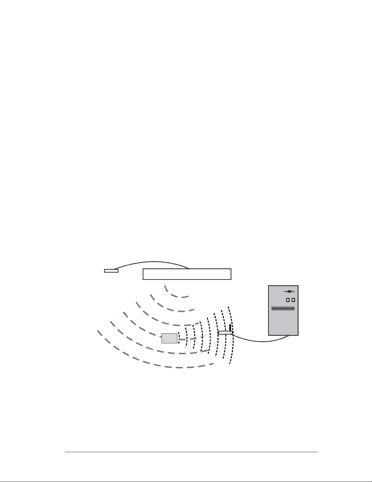
The following diagram (Figure 1) shows a very basic ActiveTag
system. The system has the following components:
Activator
•
number, to the Tag.
Transmit Antenna
•
broadcast the Activator’s wake-up signal over a defined coverage
area.
Tag
•
and identification information to a Receiver. Tags can be carried
by individuals, placed on assets or equipment, or mounted in or
on vehicles.
Receiver
•
some intelligent device – a computer or a Wiegand control panel,
for instance.
• One or more of the following: a computer running an application
or an intelligent controller.
An ActiveTag system can be as simple as a single Activator,
Receiver, transmit antenna and control panel to authorize access
through a door, or it can be a network of Receivers, Activators and
other devices controlled by a computer.
– transmits a wake-up signal, which includes its ID
– an application-specific antenna used to
– receives the wake-up signal and broadcasts its location
– receives the Tag’s broadcast and sends the data to
Activator
F
w
o
L
Transmit Antenna
al
n
g
i
S
p
u
ke
a
W
y
c
en
u
q
e
r
U
R
g
a
T
F
H
e
s
n
o
p
s
e
Receiver
Device (PC, Wiegand
control panel, etc.)
Tag
Figure 1 A simple ActiveTag System
© 2001, AXCESS Inc. 750.001.004 R0033 13
System Configuration Basics
Tags
A Tag is a small transponder that remains in a sleep state until
activated. When the Tag receives a special Very Low Frequency
(VLF) signal from the Activator, the Tag wakes up and emits an Ultra
High Frequency (UHF) radio signal. The Tag’s signal is typically its
pre-programmed identification number and the Activator’s
identification number – but could include other data as well. The
signal is generally used for detection, identification and location of
people or objects. The Receiver accepts the Tag’s transmitted
information and forwards it to a PC or control device.
AXCESS Tags are specifically designed for personnel, asset or
vehicle applications. The
identification of personnel for access control, people tracking and
resource management applications. The Tag can be personalized by
affixing a standard PVC identity card into a recess in the tag case.
Personnel Tag
provides hands-free
Activator
The
Asset Tag
can be mounted to an asset for effective protection
and monitoring. Multiple tags can be read simultaneously so that both
the asset and its carrier can be identified. This allows the asset to be
linked to one or more owners, thus providing maximum security with
greater freedom of movement.
The
Vehicle Tag
can be mounted in the vehicle for automatic, handsfree vehicle identification, tracking or access control. Vehicle Tags
are optimized for high-speed reads in vehicle applications such as
access control (residential and commercial gates), equipment
tracking and fleet management.
The
LED Test Tag
, which is also available from AXCESS Inc.,
flashes its LEDs when it is in the activation field, letting you know the
extent of the coverage area of a transmit antenna.
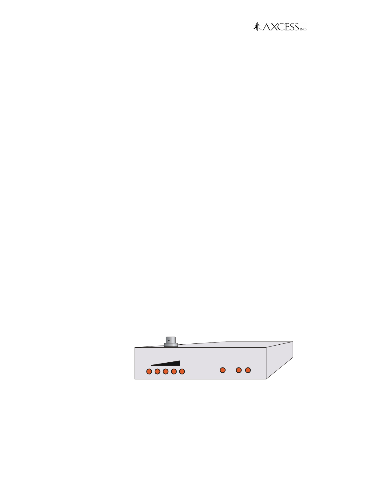
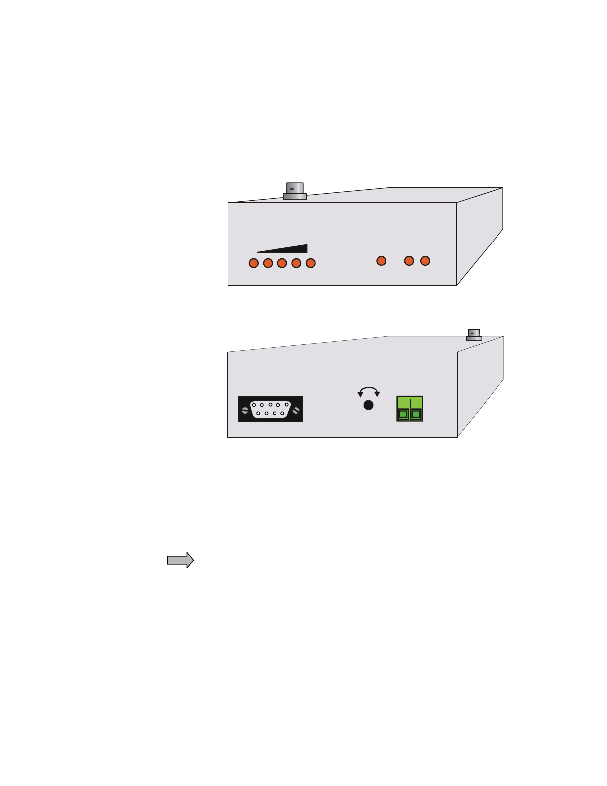
The Activator (Figure 2) broadcasts an activation signal via the
transmit antenna to wake up the tag. The transmitting antenna
attaches to the BNC connector on top of the Activator. The wakeup
signal writes the Activator’s ID Number to the tag.
AXCESS
TX OUTPUT
TM
INC
ActiveTag
ACTIVATOR
PWR TX RX
TM
Figure 2 Activator
14 750.001.004 R0033 © 2001 AXCESS Inc.
Receiver
System Configuration Basics
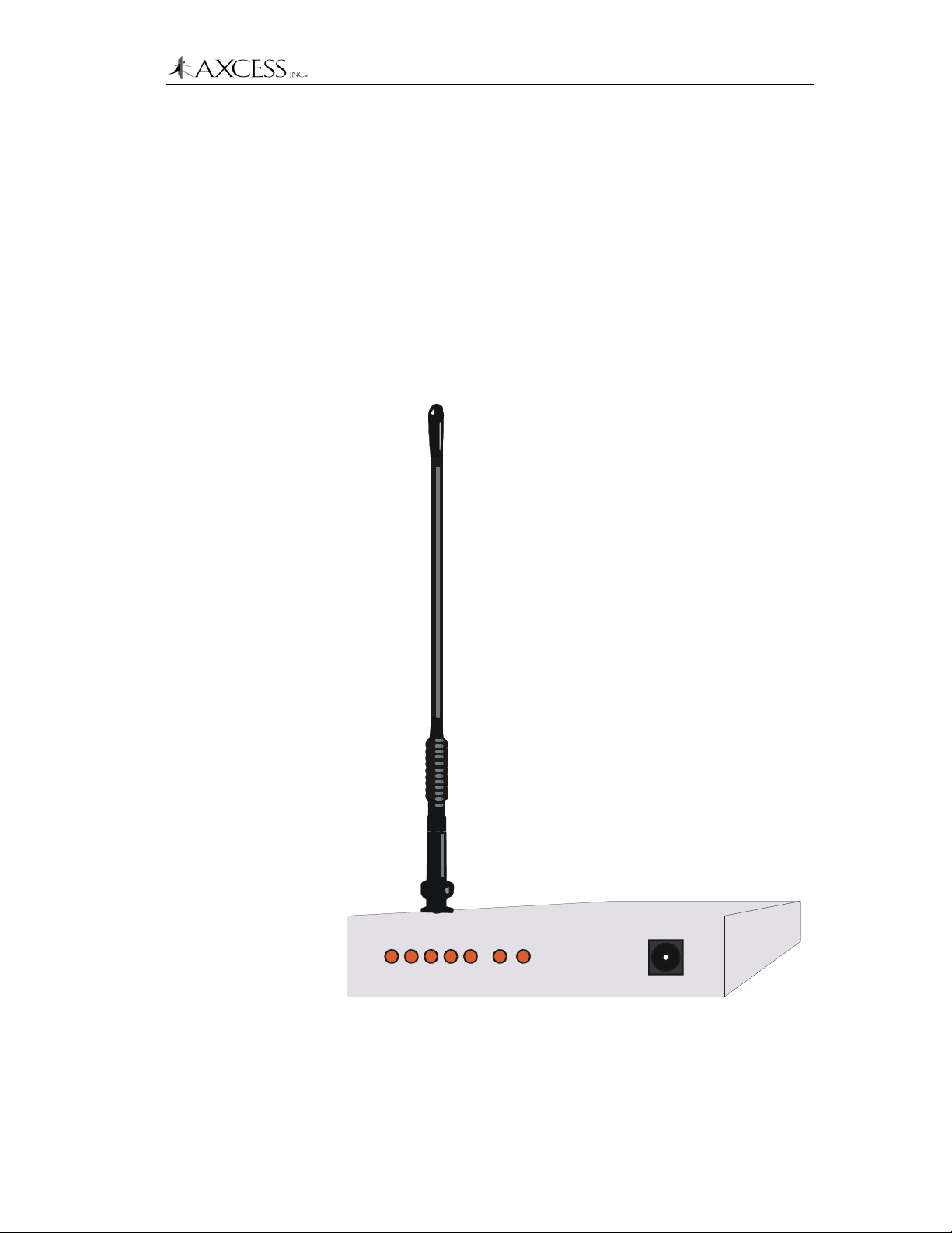
The Receiver (Figure 3) has the following functions:
• Decode the signal received from the Tag via the receive antenna.
The Receiver converts the data to a format usable by a computer
or Wiegand control panel for further processing of the
information.
• Filter Tag information according to its configuration settings.
• Send the data to a control device or a computer.
• Output control signals for activating TTL outputs or alarm points
on panels.
PWRLF
UHF
RX TX
DATA
RX TX
ActiveTag
Network Receiver
AUX
Figure 3 Receiver
© 2001, AXCESS Inc. 750.001.004 R0033 15

System Configuration Basics
Filters
The Receiver can be configured to report only selected Tag data. For
example, the Receiver can be programmed to respond to specific
Activators in a multi-Activator environment. Configuration filters also
determine what information is reported via the Wiegand interface.
Serial Output
The Receiver communicates using the EIA-232 standard, more
commonly known as RS-232C. It can connect to a communications
port on a computer or any device that accepts RS-232C data.
Wiegand Output
The Receiver can be configured to send Security Industry
Association (SIA) 26-bit Wiegand data to control panels. The
Receiver connects to the Wiegand port on the control panel by three
wires – Data One, Data Zero and Ground.
IP Output
The Receiver can be configured to connect to an IP network.
AXCESS Inc. supplies a Receiver with an integral Network Interface
Unit (NIU) to convert data from serial to Ethernet TCP/IP format.
Transmit Antennas
Because Tags receive and transmit at different frequencies, different
antennas are used for each leg of the communication. Antenna
design is related to its frequency wavelength (or fraction thereof). The
receive antenna supplied with the Receiver is designed for the UHF
spectrum and is only seven inches tall. The VLF transmit antennas
used by the Activator are loop antenna designs of varying lengths of
wire based on the application
Types of Transmit Antennas
Bar Antenna
The Bar Antenna has a VLF transmitting antenna in an enclosure that
is approximately 2 feet long, 5 inches wide and 1 inch thick. It can be
mounted indoors near a door or above the ceiling tiles and is
primarily used for personnel identification, access control or tracking
applications
Picture Frame Antenna
The Picture Frame Antenna has a transmitting antenna built into its
frame. The antenna may be mounted unobtrusively on interior walls.
The front frame and glass are hinged so that the picture can be
changed easily without removing the frame from its permanent wall
mount position.
16 750.001.004 R0033 © 2001 AXCESS Inc.

System Configuration Basics
Road Loop
The Road Loop Antenna is a large VLF transmitting antenna most
often used for activating Tags in vehicles or mobile equipment. The
Road Loop Antenna is permanently installed in the road surface and
is typically used in gate access applications. Its activation field is
capable of covering one or more lanes.
Other Antennas
Wire loops of varying size and length can be constructed to activate
tags for a variety of applications. For example, a loop of wire inside
plastic conduit can be hung above a hallway to activate tags passing
INC.
below. AXCESS
contact
Distributor Support
is regularly developing new antenna designs –
for assistance in selecting or designing
the best antenna for your application.
© 2001, AXCESS Inc. 750.001.004 R0033 17

System Configuration Basics
18 750.001.004 R0033 © 2001 AXCESS Inc.
System Configuration Basics
Introduction
This chapter introduces installation and configuration concepts. It
covers activation field behavior, application types (vehicle, personnel,
asset) with example layouts, basic installation steps, and offers tips
on installing the system.
Application Types
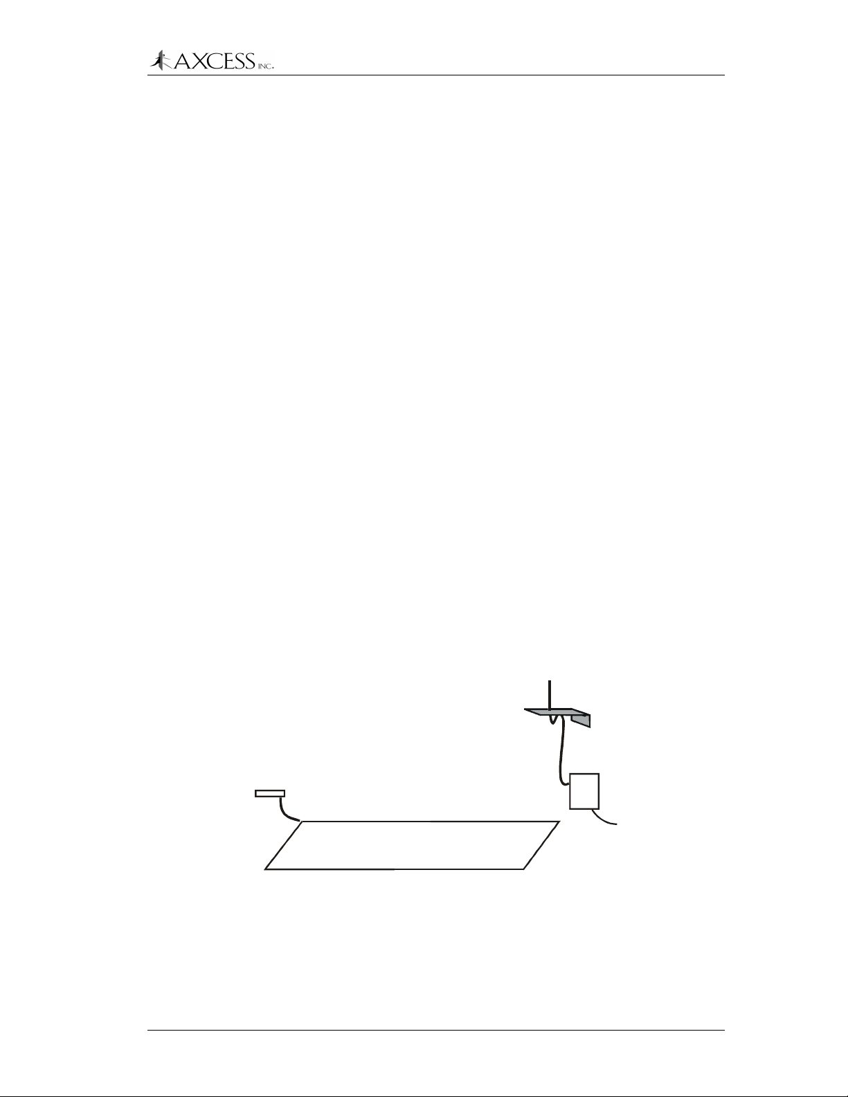
Vehicle
Vehicle applications focus on controlling access to a specified area –
a gated community or a parking garage. The ActiveTag system
integrates with 26-bit Wiegand control panels to open gates for those
cars with valid Tags.
System Placement Guidelines
• Ensure that the vehicle is committed to the lane (i.e. will not
swerve out of the lane) and will drive directly over the Road Loop
Antenna.
System Configuration Basics
• Place the Road Loop where you want the Tag to be activated. If
you want the gate to be open when the car approaches it, the
Road Loop should be placed well ahead of the gate. The Road
Loop should be at least four feet away from any other vehicle
detection or safety loops that might be installed.
• Mount the Tags in the rear window. Mount the Tags on the same
side of the road that the receive antenna has been mounted.
NOTE: Mount receiver and
Activator indoors or in a
weatherproof enclosure
Activator
Road Loop Antenna
Receiving antenna
and ground pl ane
Receiver
Wiegand or Serial
to control panel
Figure 4 Simple vehicle configuration
© 2001, AXCESS Inc. 750.001.004 R0033 19
System Configuration Basics
Personnel and/or Asset
Personnel and asset applications focus on inconspicuously
monitoring the movement of people and valuable assets in and out of
a building or through sections of the building. The applications
require that antennas be installed in hallways or near doorways.
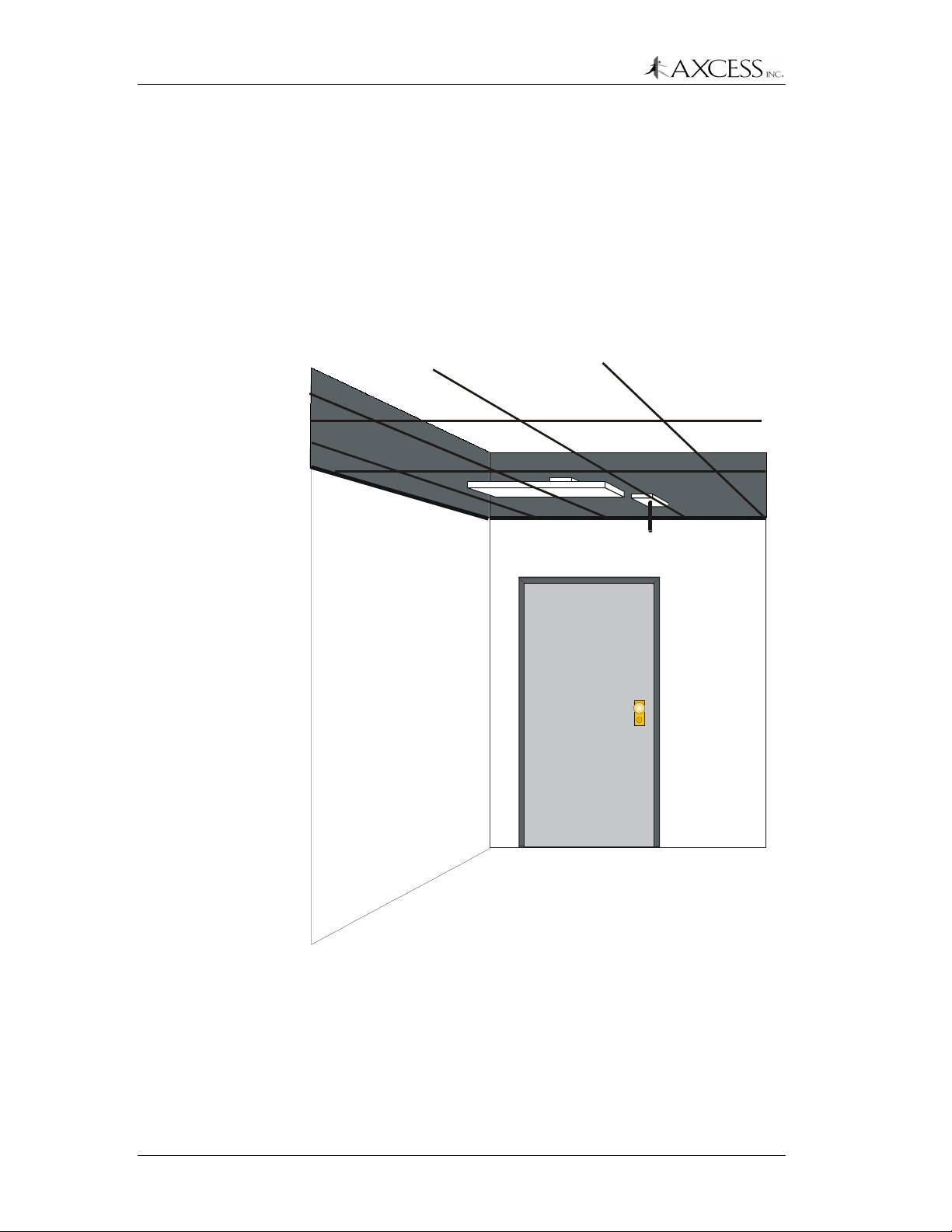
System Placement Guidelines
The Antenna, Activator and Receiver can be mounted above the
ceiling tiles above doors for personnel applications (Figure 5). Other
suitable locations include on the wall, above the door, or under a
carpet. Placing the antenna under a carpet or floor covering is
preferred for asset applications.
Bar Antenna
Activator
Receiver
Figure 5 Simple personnel configuration
20 750.001.004 R0033 © 2001 AXCESS Inc.
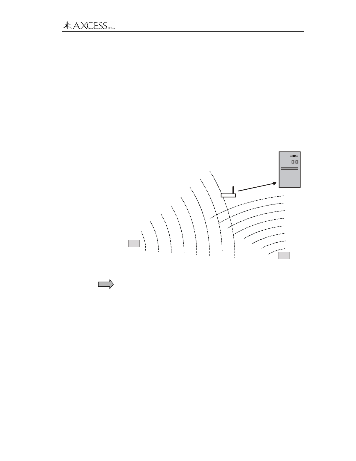
Multiple Activator Applications
Each Activator broadcasts its ID number, which the Tags then send
to a Receiver. The Receiver uses the Activator ID to determine if it
will send the Tag’s data to the control device or computer (Figure 6).
The Receiver uses the Activator ID to decide whether to send the
data to the Wiegand control panel based on the Activator ID. When
sending data serially (or over the network), the Receiver reports the
Activator ID. This information can be used to determine where a Tag
is in a building.
System Configuration Basics
Device (PC, Weig and
control panel, etc.)
Tag ID 00002
Activator ID 100
Receiver
Installation Tips
Tag ID 00002
Tag ID 00001
Activator ID 33
Tag
Activator ID 100
Tag
Figure 6 A Receiver can send data based on the Activator ID
IMPORTANT!
All Activators are given the default ID number 127 at
the factory. Each Activator in a multi-Activator application needs to be
set with a unique ID number to ensure proper behavior of the system.
Ensure that there are no other sources of similar radio frequencies
nearby. Proximity card readers and clicker systems can affect the
ActiveTag system, as can some radio-controlled sprinkler systems
and military-grade communications systems.
For best results, the receiving antenna should be no more than 35
feet from an activated Tag to receive its signal.
Waterproofing
Any electrical parts of the system exposed to the elements must be
waterproofed using sealing tape, waterproof boxes, sealing
compounds, etc.
© 2001, AXCESS Inc. 750.001.004 R0033 21
System Configuration Basics
If applicable, the RG-58 cable should be rated for direct burial.
RTV rubber silicone sealant can be used on outside connections to
protect them from the weather.
Note: The silicone seal can be broken by just pulling on a connector,
and the sealant would then need to be reapplied.
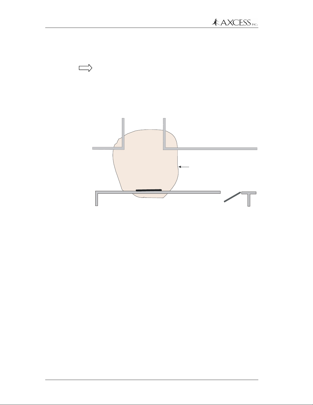
Checking Activation Fields
Figure 7 shows a real-life example of an activation field. The gray
area is the activation field of a Picture Frame Antenna mounted in a
hall.
Activation Field
Swing Frame Antenna
Figure 7 An activation field.
Always test your field to ensure that you get the coverage you want.
Also, ensure that the activation field does not cover any areas where
Tags may be for long periods of time – a parking space next to the
activation field, for instance.
Use the LED Test Tag and the TX Control on the Activator to modify
the activation field. This is covered in the section
Activation Field
, page 32.
Resizing the
Cable Length for Antennas
Best results are achieved when the antenna supplied with the
Receiver is connected directly to its BNC connector. The maximum
recommended cable length between the Receiver and the antenna is
25 feet (Figure 8). However, distances up to 50 feet are possible with
minimal degradation in performance. When the receive antenna is to
be located remote from the Receiver, it is recommended that one
use an antenna bracket kit supplied by AXCESS Inc. or an AXCESS
approved mounting method.
22 750.001.004 R0033 © 2001 AXCESS Inc.
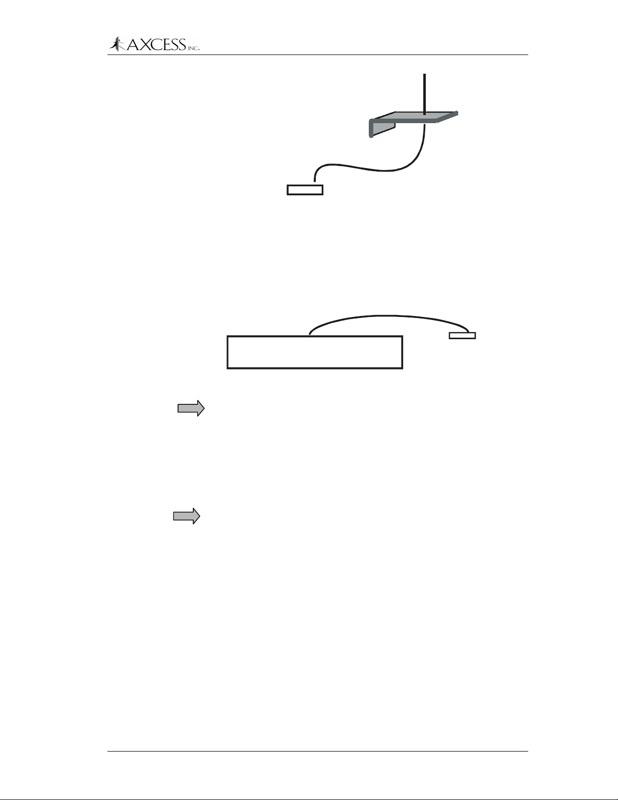
System Configuration Basics
Receiving Antenna
RG-58 - 25 feet maximum
Receiver
Figure 8 Max distance between Receiver and receive antenna
Best results are achieved when the transmit antenna is no more than
50 feet from the Activator. However, distances of up to 100 feet are
possible with minimal degradation in performance. Contact Customer
Support for assistance with special installation needs.
RG-58 - 50 feet maximum
Activator
Figure 9 Max distance between Activator and transmit antenna
IMPORTANT!
different cable is used, the cable length exceeds recommendations,
the cable is kinked, or the BNC connectors are improperly installed.
Basic Installation Steps
The following list shows the order in which the ActiveTag system
should be installed.
Step 1: IMPORTANT!
Step 2:
Step 3:
Step 4:
Transmitting Antenna
System performance may be adversely affected if a
Bench test communications between the
ActiveTag system and the controller or device to which it
will be connected.
Configure the Activator – Give each Activator a unique ID
number if there will be multiple Activators on site.
Configure the output of the Receiver – for example, enable
Wiegand output if required. If there are multiple Activators,
program how the Receiver should respond to the Activator
ID(s).
Lay the entire ActiveTag system out and test the antenna
fields before permanently installing any piece of the
system.
Step 5:
Step 6:
Install the Activator and Receiver.
Install the transmit and receive antennas.
© 2001, AXCESS Inc. 750.001.004 R0033 23

System Configuration Basics
Step 7:
Step 8:
Step 9:
Adjust the size of the activation field.
Mount the Tags.
Connect the system to the controller or software and test
thoroughly.
24 750.001.004 R0033 © 2001 AXCESS Inc.
Configuring and Installing the Activator
Introduction
The Activator creates and optimizes the radio signal that wakes up
the Tag.
AXCESS
TM
IN C
TX OUTPUT
ActiveTag
ACTIVA T OR
PWR TX RX
TM
DATA
Figure 10 Front of the Activator
DATA
RS-232
TX CNTL
+
-
POWER
+24VDC
GND
Figure 11 Back of the Activator
Activator IDs
An Activator sends its ID number in the wake-up signal. The Tag
then transmits both its own ID and the device ID of the Activator to
the Receiver. From this information, the Receiver uses the Activator
ID to determine what action to take with the Tag data.
IMPORTANT!
All Activators are given the same ID number (127) at
the factory. Each Activator in a multi-Activator application needs to be
set with a unique ID number to ensure proper behavior of the system.
© 2001, AXCESS Inc. 750.001.004 R0033 25

Configuring and Installing the Activator
Supplying Power
Activators come with a 24V DC, 1 Amp power transformer that plugs
into a standard 110V AC outlet. The transformer is pre-wired into the
terminal block at the factory. If uninterruptible power is an issue, a
backup battery or UPS can be used.
Step 1:
Step 2:
Step 3:
When power is supplied to the Activator, the LEDs labeled PWR and
TX on the front will light (Figure 10).
Setting the Activator ID
An Activator ID can be set by two methods:
• Serial commands (requires a computer or terminal device). This
• Hardware jumpers if no terminal is available
Method 1: Serial Commands
Required Materials
• A computer or portable terminal with a free communications port.
Connect the antenna to the Activator in order for the
antenna auto-tune feature to function when power is
applied. Auto-tune takes place whenever power is cycled.
Plug the power terminal block into the back of the Activator
(Figure 11).
Plug the AC adapter into a 110-volt outlet.
is the preferred method for setting the Activator ID
A laptop is recommended because it can be taken into the field
easily.
• A terminal program for communicating with an Activator.
HyperTerminal is convenient since it is standard with the
Windows
programs, such as ProCom, etc., can also be used.
• A standard one-to-one (straight-through) computer modem RS-
232 cable with a DB9 male connector for the Receiver and
suitable connector for the PC/terminal.
IMPORTANT!
adapter.
Connecting a Computer to the Activator
Step 1:
Step 2:
26 750.001.004 R0033 © 2001 AXCESS Inc.
TM
operating system. Other terminal emulation
DO NOT use a null-modem cable or null-modem
Ensure power is applied to the Activator.
Attach the DB9 male connector of the RS-232 cable to the
Data RS-232 port on back of the Activator.
Configuring and Installing the Activator
Step 3:
Communicating via Windows HyperTerminal
Step 1:
Step 2:
Attach the other end of the RS-232 cable to an open com
port on the computer.
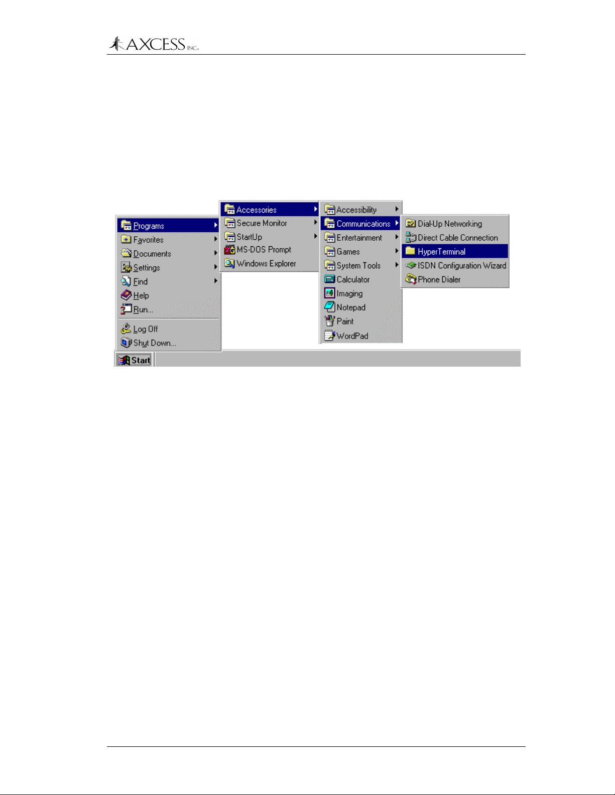
On the computer’s desktop, click the
Start menu will appear (Figure 12).
From the Start menu, select
Communications, HyperTerminal.
Programs, Accessories
Start
button. The
,
Figure 12 Accessing HyperTerminal from the Start Menu
Step 3:
Step 4:
Step 5:
Step 6:
In the
Explorer
Hypertrm.exe
application.
In the
Connection Description
enter any name for the connection in the
select the first icon in the
button.
In the
Connect To
port to which the Receiver or Activator is connected from
the
Connect Using
gray out. Click the OK button.
In the
Com Properties
following information:
Bits per second (Baud) 9600
Data Bits 8
Parity None
Stop Bits 1
Flow Control None
window that appears, double-click the
icon. This launches the HyperTerminal
dialog box that appears,
Name
selection box. Click the
Icon
dialog box that appears, select the com
drop-down list. The other options will
dialog box that appears, enter the
field, and
OK
Step 7:
© 2001, AXCESS Inc. 750.001.004 R0033 27
Click the OK button.

Configuring and Installing the Activator
Changing the Activator ID Number
If your ActiveTag system is using Version 5 Tags, type one of the
numbers in Table 1 followed by an exclamation point (!). The number
will be accepted at the Activator’s ID number.
3 34 70 103
13 44 72 105
14 47 75 106
21 52 80 113
22 55 83 114
24 57 93 124
27 58 94 127 – default ID
33 69 100
If your system is using Version 6 Tags, type any number between 1
and 250 for the Activator ID. For example, if you type:
Table 1 Valid Activator IDs
113!
113!
113!113!
The Activator will respond with
ID = 113
ID = 113
ID = 113ID = 113
Method 2: Hardware
When set with jumpers, the Activator ID is a binary number
represented by jumpers. A 1 is represented by a jumper on a header
and a 0 is represented by an absence of a jumper.
ID Jumpers ID Jumpers
3 0 0 0 0 0 0 1 1 70 0 1 0 0 0 1 1 0
13 0 0 0 0 1 1 0 1 72 0 1 0 0 1 0 0 0
14 0 0 0 0 1 1 1 0 75 0 1 0 0 1 0 1 1
21 0 0 0 1 0 1 0 1 80 0 1 0 1 0 0 0 0
22 0 0 0 1 0 1 1 0 83 0 1 0 1 0 0 1 1
24 0 0 0 1 1 0 0 0 93 0 1 0 1 1 1 0 1
27 0 0 0 1 1 0 1 1 94 0 1 0 1 1 1 1 0
33 0 0 1 0 0 0 0 1 100 0 1 1 0 0 1 0 0
34 0 0 1 0 0 0 1 0 103 0 1 1 0 0 1 1 1
44 0 0 1 0 1 1 0 0 105 0 1 1 0 1 0 0 1
47 0 0 1 0 1 1 1 1 106 0 1 1 0 1 0 1 0
52 0 0 1 1 0 1 0 0 113 0 1 1 1 0 0 0 1
55 0 0 1 1 0 1 1 1 114 0 1 1 1 0 0 1 0
57 0 0 1 1 1 0 1 0 124 0 1 1 1 1 1 0 0
58 0 1 0 0 0 1 0 1 127 0 1 1 1 1 1 1 1
69 0 1 0 0 0 1 1 0
Table 2 Jumper settings for Activator IDs
28 750.001.004 R0033 © 2001 AXCESS Inc.

Configuring and Installing the Activator
Note: Before the Activator ID is set with jumpers, the default ID is
127, although there are no jumpers on the headers.
Note: Once an Activator ID is set by jumpers, it cannot be reset with
serial commands. In order for serial commands to take effect, the
jumpers must be removed. However, even with the jumpers removed
the Activator will maintain the ID that had been set with jumpers until
reprogrammed with the serial command.
Step 1:
Step 2:
Power down the Activator.
Using needle-nose pliers, place jumpers on headers JP12
through JP19 (Figure 13) to represent the ID number in
binary. A jumper on a header represents a one and
absence of a jumper is a zero. JP12 is the least significant
bit and JP19 is the most significant bit.
Front of Activator
Antenna BNC
Connector
JP12
JP19
Jumpers for setting the
Activator ID
Least Significant Bit
Most Significant Bit
Figure 13 Activator ID jumpers
JP12
JP19
Activator ID 13- 00001 101
JP12
JP19
Activator ID 100 - 01100100
Figure 14 Examples of Activator IDs
IMPORTANT!
Ensure that the Receiver is configured to accept the
new Activator ID so that it may process the Tag data properly. Please
see the section Configuring the Receiver, page 34, for instructions on
programming the Receiver to respond to the new Activator ID.
© 2001, AXCESS Inc. 750.001.004 R0033 29

Configuring and Installing the Activator
Other Serial Port Commands
There are also commands available to list a help screen and change
the baud rate of the Activator’s serial port.
Receiving Help
Typing a question mark (?) displays a help screen listing all
commands available for the Activator:
c = 4800cps
c = 4800cps
c = 4800cpsc = 4800cps
d = 9600cps
d = 9600cps
d = 9600cpsd = 9600cps
e = 19200cps
e = 19200cps
e = 19200cpse = 19200cps
<Num>! = ID
<Num>! = ID
<Num>! = ID<Num>! = ID
t = Automatic Tuning
t = Automatic Tuning
t = Automatic Tuningt = Automatic Tuning
<Num>s = Set Tuning
<Num>s = Set Tuning
<Num>s = Set Tuning<Num>s = Set Tuning
Changing the Baud Rate
If you want to connect the Activator to a serial device, you can
change the Activator’s baud rate to match the baud rate of the
device. The following baud rates are permissible:
Baud Rate Command
4800 c
9600 d – This is the default baud rate
19200 e
Table 3 Baud Rates
Type a lower case letter representing the desired baud rate (Table 3).
You do not need to press the Enter key. For example:
cccc
This will change the baud rate to 4800 bps. After you have set the
baud rate, you will need to adjust the port settings of the serial
device.
Tuning the Activation Field
The Activator tunes the activating antenna to its environment. It can
either be given commands to tune the antenna or it will automatically
tune the antenna upon powering up.
To tune the activating antenna via serial command, type the letter:
tttt
Note: The Set Tuning command (<Num>s) listed in the help screen
was created for testing the system. Use the t command or cycle the
power on the system to tune the antenna.
30 750.001.004 R0033 © 2001 AXCESS Inc.

Activator Installation
The Activator originates the signal that is broadcast by the transmit
antenna. The Activator should be installed as close as possible to the
transmit antenna, and up to 50 feet away by cable distance from the
antenna. Distances up to 100 feet are possible in some cases with
minimal effect on system performance. Contact Distributor Support
for assistance with extended distance installations. The shorter the
cable, the better the system will perform.
Required Materials
The following materials are necessary for a successful installation:
• Power drill and bits
• Screwdrivers – Phillips and flathead
• Two screws (for wall mount)
Note:
on, you may want to use #10 molly bolts.
Mounting the Activator
IMPORTANT!
ActiveTag System, first lay out and test the entire system.
Configuring and Installing the Activator
Depending on the surface that the Activator will be mounted
Before permanently mounting any piece of the
The Activator should be a maximum of 50 feet from the transmit
antenna for best performance.
Holes on the bottom of the Activator allow it to be mounted vertically
to a wall or other surface.
IMPORTANT!
transmitting antenna.
Cycle the power on the Activator after attaching the
© 2001, AXCESS Inc. 750.001.004 R0033 31

Configuring and Installing the Activator
Resizing the Activation Field
The area of Tag activation can be controlled by adjusting the size of
the activation field. For example, you may want to shrink the
activation field for a Picture-Frame antenna to concentrate the field
near a doorway, preventing activation of tags further up the hall.
Note: Each Activator is shipped from the factory with its activation
control adjusted to its highest level.
Adjusting the Field
The size of the activation field is controlled by the TX CNTL screw on
the back of the Activator (Figure 15). The screw can turn in one
direction 30 times. After it has been turned 30 times in one direction,
it will make a soft clicking sound. The clicks indicate that continuing
in this direction will no longer have an effect on the field’s size. When
you hear this sound, the wake-up field has been adjusted to one
extreme or the other.
TX CNTL
-
+
Figure 15 Adjusting the size of the activation field
To reduce the activation field
clockwise
with an LED Test Tag to ensure that the field is the size that you
want.
IMPORTANT!
control is turned down too low. To fix this, turn the screw
clockwise until it clicks. Then slowly reduce the field by turning the TX
CNTL screw clockwise while checking its size.
To enlarge the activation field
clockwise
After the field is adjusted,
with the supplied tuning wand. Constantly check the field
The system will stop functioning if the activation
. When it clicks, it has been turned up as high as possible.
- Rotate the TX CTRL screw
counter
– Turn the screw
cycle the power on the Activator.
counter-
-
32 750.001.004 R0033 © 2001 AXCESS Inc.

Configuring the Receiver
Introduction
The Receiver receives the Tag’s broadcast signal via its receiving
antenna and sends the Tag data to a PC or control device based on
how it has been programmed to respond to the Activator ID.
PWRLF UHF
RX TX
+5VGD1D0
Wiegand
Output
Connecting Power to the Receiver
All Receivers come with a 5 VDC, 400 mA power transformer that
plugs into a 110 VAC outlet. If uninterruptible power is an issue, a
backup battery or UPS can be used. When power is supplied to the
Receiver, the power indicator LED on the front will light up.
DATA
RX TX
ActiveTag
Network Receiver
AUX
Figure 16 Front of the Receiver
RS-232
5VDC
GND
Power
24VDC
Figure 17 Back of the Receiver
Step 1:
Ensure that the 110 VAC outlet is near the Receiver and is
easily accessible.
Step 2:
Step 3:
Plug the AC adapter into the jack labeled
back
of the Receiver (Figure 17).
Plug the unit into the power outlet.
5VDC
on the
© 2001, AXCESS Inc. 750.001.004 R0033 33

Configuring the Receiver
Configuring the Receiver
Receiver Defaults
The Receiver has the following factory default settings:
• Wiegand and TTL output capabilities enabled.
• Wiegand and serial output is enabled.
• Tag data with any valid Activator ID will be output.
• No Wiegand data will be output for panic or tamper Tag alarms.
• Neither TTL output will fire for valid Tag data or panic or tamper
Tag alarms.
• Diagnostics are turned off.
• Serial output is set at 9600 baud with long format –
RRRAAAFFFTTTTT where RRR is the Receiver ID, AAA is the
Activator ID, FFF is the facility code and TTTTT is the Tag ID.
• Receiver ID is 001.
These settings can be modified with commands given to the
Receiver via HyperTerminal.
Required Materials
• A computer with a terminal program and a free communications
port.
• A standard one-to-one computer modem RS-232 cable with a
DB9 male connector (Receiver end) and a suitable connector for
the PC/terminal end.
IMPORTANT!
adapter.
Connecting a Computer to the Receiver
Step 1:
Step 2:
Attach the DB9 male connector of the RS-232 cable to the
RS-232 port on the Receiver.
Attach the other end of the RS-232 cable to the computer.
DO NOT use a null-modem cable or null-modem
34 750.001.004 R0033 © 2001 AXCESS Inc.

Communicating via HyperTerminal
Step 1:
Start HyperTerminal. Details can be found in the section
Communicating via Windows HyperTerminal,
Configuring the Receiver
page 27
Step 2:
Step 3:
Step 4:
Step 5:
Receiver Responses
All commands have the basic format of <number><character>. It is
unnecessary to press the Return key after typing the command.
In the Connection Description dialog box that appears,
enter any name for the connection in the Name field, and
select the first icon in the Icon selection box. Click the OK
button.
In the Connect To dialog box that appears, select the com
port to which the Receiver is connected from the Connect
Using drop-down list. The other options will gray out. Click
the OK button.
In the Com Properties dialog box that appears, enter the
following information:
Bits per second (Baud) 9600
Data Bits 8
Parity None
Stop Bits 1
Flow Control None
Click the OK button.
When a command is given to the Receiver, the Receiver will respond
with one of the following codes:
00
Command completed successfully
05
Value entered is out of bounds
06
Invalid or unknown command
Note:
Other command-specific responses are documented with the
corresponding command.
© 2001, AXCESS Inc. 750.001.004 R0033 35

Configuring the Receiver
Setting up a Wiegand System
Responding to Activator IDs
By default, the Receiver will only output Wiegand data from Tags
activated by Activator ID 127. To change the Activator ID, type the
new Activator ID number followed by a capital W:
<number>W
<number>W
<number>W<number>W
This is known as a Wiegand ID. The default is to only output reads
corresponding with this Activator.
To enable the Receiver to respond to multiple Activator IDs, type:
33c
33c
33c33c
The Wiegand output of the Receiver will now include all tag reads
from Activators listed as valid Activator ID’s for serial output in
addition to the Wiegand ID. See
page 38, for the list of Activator IDs and how to configure them.
To return the Wiegand output to the single the single Wiegand
Activator ID, type:
Responding to Activator IDs
,
19c
Alarm Output
By default, the Receiver does not output Tag data containing alarm
codes from Panic or Tamper Tags via the Wiegand port. To enable
alarm data output, type:
26c
26c
26c26c
To disable alarm data output (default state), type:
12c
12c
12c12c
Setting up a Serial or LAN System
Setting the Baud Rate
The following commands are available for configuring the Receiver’s
serial port:
Command Action
23c
23c
23c23c
24c
24c
24c24c
25c
25c
25c25c
Set the baud rate to 4800.
Set the baud rate to 9600. Default.
Set the baud rate to 19200 for NIU connections.
Serial Output
The default format for Tag data sent out the serial port is:
R R R A A A F F F T T T T T LF CR
R R R A A A F F F T T T T T LF CR
R R R A A A F F F T T T T T LF CRR R R A A A F F F T T T T T LF CR
36 750.001.004 R0033 © 2001 AXCESS Inc.

Configuring the Receiver
Where
R R R
R R R
R R RR R R
is the Receiver ID,
the facility code,
Return, and
LF
LF
LFLF
T T T T T
T T T T T
T T T T TT T T T T
is Line Feed.
is the Tag ID number,
A A A
A A A
A A AA A A
is the Activator ID,
is Carriage
CR
CR
CRCR
F F F
F F F
F F FF F F
To make the Receiver backwards compatible with AXCESS NT132
systems, type:
36c
36c
36c36c
The serial output will now have the short format:
A A A F F F T T T T T LF CR
A A A F F F T T T T T LF CR
A A A F F F T T T T T LF CRA A A F F F T T T T T LF CR
To return to the long format out (default), type:
21c
Optimizing Serial Output
The speed at which the Receiver processes data can be maximized
by eliminating the extra steps required to output Wiegand data and
check TTL output control settings.
To optimize serial output, turn off the Receiver’s Wiegand output by
typing:
29c
29c
29c29c
To restore Wiegand output (default), type
is
15c
If your installation does not require TTL outputs, it can be further
optimized by disabling TTL outputs with the following command:
35c
35c
35c35c
Note: This command will also disable Wiegand ouputs.
To restore TTL output operations, type:
20c
Note: When the Network Receiver is sending data via the serial port,
the LED labeled DATA TX will alternately flash from red to green.
Observing this LED on the front of the unit will help in verifying proper
operation of a Network Receiver.
© 2001, AXCESS Inc. 750.001.004 R0033 37

Configuring the Receiver
Responding to Activator IDs
The only Tag data that a Receiver will output via the serial port must
contain a valid Activator ID. The Receiver maintains a list of valid
Activator IDs. By default, the Receiver accepts Tag data from
Activators with the following IDs:
3 34 70 103
13 44 72 105
14 47 75 106
21 52 80 113
22 55 83 114
24 57 93 124
27 58 94 127 – default ID
33 69 100
Table 4 Default Activator IDs
Deleting an Activator ID
If the Receiver picks up signals from two or more activation fields and
you want the Receiver to only send data from a select set of
activation fields, delete the unwanted Activator ID(s) from the
Receiver’s list. To delete an Activator ID, type the ID number followed
by a minus sign:
<number>-
<number>-
<number>-<number>-
If the Activator ID has not been programmed into the Receiver, the
Receiver will respond with the error code:
04
04
0404
You must have at least one Activator that the Receiver can respond
to. If you try to delete all the Activator IDs, the Receiver will respond
with the error code:
03
03
0303
And will not allow you to delete the last Activator ID.
Clearing Accepted Activator IDs
To remove all the accepted Activator IDs, type:
37c
37c
37c37c
The Receiver will still pass the default Activator ID 127.
Adding an Activator ID
To add an Activator ID, type the Activator ID followed by a plus sign:
<number>+
<number>+
<number>+<number>+
38 750.001.004 R0033 © 2001 AXCESS Inc.

If the entry is a duplicate, the Receiver will respond with the error
code:
If more than 34 Activator IDs have been entered – the maximum
number the Receiver can hold – the Receiver will respond with error
code:
You will need to delete some Activator IDs on the list to make room.
Restoring Default IDs
To reset the list to the valid Activator ID numbers, type:
All Tag data from Activator IDs listed in Table 4, page 38, and status
codes 000 (alarm from Panic or Tamper Tags) and 254 through 255
will be output to the PC or control device.
Setting the Receiver ID
Receiver IDs are used by ActiveTrac software to determine from
which zone a Tag reported. By default, the Receiver ID is 001. To
give the Receiver a new ID, type:
01
01
0101
02
02
0202
34c
34c
34c34c
Configuring the Receiver
<number>I
<number>I
<number>I<number>I
Where
<number>
<number>
<number><number>
is between 000 and 999.
Enabling TTL outputs (Logic Control)
The ActiveTag Receiver has two Transistor-Transistor-Logic (TTL)
outputs – each can be set to go from Low (inactive) to High (active)
upon a tag read. The
provides a list of configuration commands.
TTL output 1 TTL output 2 Action
<number>D
<number>D <number>E
<number>D<number>D
10c
10c 11c
10c10c
16c
16c 17c
16c16c
30c
30c 31c
30c30c
13c
13c 14c
13c13c
output level is 3.3VDC.
<number>E
<number>E<number>E
11c
11c11c
17c
17c17c
31c
31c31c
14c
14c14c
The following table
Set the length of the activation
signal in seconds. Valid numbers
are 000 through 255. The default is
005 seconds.
Set output to go from
Low
to
High
Do not activate TTL output for a
valid Tag read. Default
Activate TTL output for a valid Tag
read.
Do not activate TTL output when
alarm code received from a Panic
or Tamper Tag. Default.
.
© 2001, AXCESS Inc. 750.001.004 R0033 39

Configuring the Receiver
Diagnostic Mode
Diagnostic Mode allows you to troubleshoot the ActiveTag system by
displaying all data received from all Tag broadcasts picked up by the
Receiver -- including Tag data with Activator IDs that have not been
programmed into the Receiver.
To enter Diagnostic Mode, type:
The following is an example of how the Receiver will respond:
27c
27c 28c
27c27c
39c
39c
39c39c
28c
28c28c
00110602401234
00110602423235
Activate TTL output when alarm
code received from Panic or
Tamper Tag.
Where
001
001
001001
Code and
is the Receiver ID;
01234
01234 and 23235
01234 01234
23235
2323523235
is the Activator ID;
106
106
106106
are the IDs of Tags in the field. If the
024
024
024024
is the Site
serial output has been set to short format, then the Receiver ID will
not be displayed.
Diagnostic Outputs
The Receiver will output every Tag transmission that it receives,
whether or not the Tag data contained a valid Activator ID.
IMPORTANT!
Do not use Diagnostic Mode as the standard Receiver
output to interface with your software. Diagnostic Mode allows crosstalk – Receivers will output data for Tags awakened by any 132 kHz
signal – all Activators, any interference, etc.
Code 254
In some earlier tag versions, code 254 is broadcast in place of an
Activator ID to indicate that a Tag was activated by a valid activation
field -- but could not to determine the Activator’s ID number. By
default, later tag versionsare not programmed to transmit a 254 code.
Wiegand Output
While a Receiver sends Tag data to HyperTerminal as rapidly as it’s
received, it will still buffer the data being sent to the Wiegand control
panel. When a Receiver that has been configured to output Wiegand
data is in Diagnostic Mode, all Tag information is sent to the control
panel. Therefore, it’s recommended Wiegand output be disabled -or, disconnect the Wiegand terminal when in
Diagnostics
mode.
40 750.001.004 R0033 © 2001 AXCESS Inc.

Turning off Diagnostic Mode
To turn off the Diagnostic mode, type:
22c
22c
22c22c
Configuring the Receiver
IMPORTANT!
Failure to do so can result in cross-talk, garbled output and erratic
control device performance.
Viewing Configuration Settings
To see the configuration settings of the Receiver, type:
38c
38c
38c38c
The Receiver will respond with its configuration settings. The
following is an example of the response:
127|33|34|106
127|33|34|106
127|33|34|106127|33|34|106
Config: DDDDDDDD*DD D=005 E=005 I=001 L=125
Config: DDDDDDDD*DD D=005 E=005 I=001 L=125
Config: DDDDDDDD*DD D=005 E=005 I=001 L=125Config: DDDDDDDD*DD D=005 E=005 I=001 L=125
T=013 W=127
T=013 W=127
T=013 W=127T=013 W=127
Where the list of numbers is the list of valid Activator IDs. The eleven
characters – Ds and *s – indicate the following:
DDDD
Default setting
****
Changed setting
The following is the list of the default settings in order:
1. Wiegand data output on alarm OFF
Always turn off Diagnostic Mode when finished.
2. TTL output 1 on alarm OFF
3. TTL output 2 on alarm OFF
4. Wiegand data output ON
5. TTL output 1 on valid read OFF
6. TTL output 2 on valid read OFF
7. Serial data output ON
8. Serial Activator IDs for Wiegand OFF
9. Transmit long Tag ID format ON
10. Diagnostic mode OFF
11. Wiegand/TTL output capabilities ON
The rest of the configuration is for the following:
D TTL output 1 signal duration in seconds
E TTL output 2 signal duration in seconds
I Receiver ID
© 2001, AXCESS Inc. 750.001.004 R0033 41

Configuring the Receiver
L Redundant Tag buffer for Wiegand output in tenths of a
T Interval between Wiegand outputs in tenths of a second
W Wiegand Activator ID number
second (See
Configuration
Appendix C: Advanced Wiegand
for more information)
42 750.001.004 R0033 © 2001 AXCESS Inc.

Configuring the NIU
Introduction
The Network Interface Unit (NIU) is provided with Receivers that can
connect to a LAN/WAN. The NIU allows the Receiver to connect to
the LAN by providing a fixed IP address to the Receiver and
converting the Receiver’s serial data to TCP/IP packets. The NIU
consists of a DB25 serial port, a 10 base 100 Ethernet connection
(RG45), and a power transformer.
Like the Receiver, the NIU must be configured via a terminal
emulation program such as
In order to allow PC applications to connect to the Receiver and gain
access to the tag read data, the NIU must be assigned a fixed IP
address.
If you plan to have a PC and the Receiver(s) on a private hub (not
connected to the company network or the Internet), then you can
assign any IP addresses. For example, the PC could be
200.200.200.1. [Note: On the PC, the IP address is set in Settings,
Control Panel, Network, TCP/IP components, Properties, IP Address,
Specify an IP address, fill in 200.200.200.1, for Subnet Mask fill in
255.255.255.0, click OK, click OK, PC will reboot.] The first Receiver
could be at 200.200.200.2 and the next at 200.200.200.3. The
procedure below describes how to setup the IP address and other
parameters on the NIU.
HyperTerminal
.
If you plan to put the Receiver on the corporate network, or the
Internet, you will need to get an IP address assigned by your network
manager. The PC application software will not work with dynamic IP
address assignment. Once you have the IP address from the network
manager, the procedure below describes how to assign that address
to the NIU.
Connecting the NIU to the PC
Step 1: IMPORTANT!
Step 2:
Step 3:
Connect one end of the null-modem serial cable to the
DB25 port of the NIU (Figure 18).
Connect the other end of the null-modem cable to an open
com port on your computer.
Ensure that the NIU’s power is
OFF
.
© 2001, AXCESS Inc. 750.001.004 R0033 43

Configuring the NIU
Power
Supply
To the computer’s
COM port
ETHERNET
10/100
OK
100
LINK
SERIAL
POWER
NIU
Step 4:
Step 5:
Step 6:
Step 7:
Step 8:
RESET
6VDC
Network Interface Unit
SERIAL
Null modem serial cable
DB-25 to DB-25
Figure 18 Connecting the NIU to the computer
Launch HyperTerminal.
In the Com Properties dialog box, enter the following
information:
Bits per second (Baud) 9600
Data Bits 8
Parity None
Stop Bits 1
Flow Control Hardware
Click the OK button. You now have an active connection to
the NIU with HyperTerminal.
Power up the NIU. After 30 seconds, the NIU initialization
screen will appear and information will scroll past.
After you see
%%Ethernet Address xx-xx-xx-xx-xx-xx
line, press the Enter key.
Step 9:
At the
Local_1>
Local_1>
Local_1>Local_1>
prompt, type
set priv
set priv
set privset priv
. The NIU will
prompt you for a password.
Step 10:
Type the default password,
system
system
systemsystem
. The password will not
appear on the screen when it is typed.
Step 11:
At the
Local_1>
Local_1>
Local_1>Local_1>
xxx.xxx.xxx.xxx
xxx.xxx.xxx.xxx
xxx.xxx.xxx.xxxxxx.xxx.xxx.xxx
prompt, type
change ipaddress
change ipaddress
change ipaddresschange ipaddress
, where xxx.xxx.xxx.xxx is the IP
address that you want to give to the NIU.
Step 12:
Enter
change subnet mask xxx.xxx.xxx.xxx
change subnet mask xxx.xxx.xxx.xxx
change subnet mask xxx.xxx.xxx.xxxchange subnet mask xxx.xxx.xxx.xxx
Local_1>
Local_1>
Local_1>Local_1>
prompt. The typical subnet mask is
at the
255.255.255.0.
Step 13:
To specify a gateway, type
xxx.xxx.xxx.xxx
at the
change gateway
Local_1>
prompt. A gateway
should be specified when you want to connect to the NIU
from another network. Your network manager will be able
to supply the gateway address if needed.
44 750.001.004 R0033 © 2001 AXCESS Inc.

Configuring the NIU
Step 14:
Step 14:
Setting up the Serial Port
The serial port on the NIU should be configured so that it can
communicate with the Receiver. To properly configure the serial port,
type the following commands at the
Command Description
Change modem control enable
Change modem control enable
Change modem control enableChange modem control enable
Change flow control none
Change flow control none
Change flow control noneChange flow control none
To ensure that no other network IP address assignment
protocols – BOOTP, DHCP or RARP – reassign the IP
address, type the following commands at the prompt:
Local_1> Change DHCP disable
Local_1> Change DHCP disable
Local_1> Change DHCP disableLocal_1> Change DHCP disable
Local_1> Change BOOTP disable
Local_1> Change BOOTP disable
Local_1> Change BOOTP disableLocal_1> Change BOOTP disable
Local_1> Change RARP disable
Local_1> Change RARP disable
Local_1> Change RARP disableLocal_1> Change RARP disable
At the
Local_1>
Local_1>
Local_1>Local_1>
terminal will display the IP information that you have
provided. Ensure that it is correct.
prompt, type
Local_1>
Allows the NIU to monitor for a
valid serial connection
Direct serial port not to use flow
control
show server
show server
show servershow server
prompt:
. The
Change break none
Change break none
Change break noneChange break none
Change serial delay 0
Change serial delay 0
Change serial delay 0Change serial delay 0
Change access remote
Change access remote
Change access remoteChange access remote
Change verify disable
Change verify disable
Change verify disableChange verify disable
Change silentboot enable
Change silentboot enable
Change silentboot enableChange silentboot enable
Change speed 9600
Change speed 9600
Change speed 9600Change speed 9600
The
Show Port
Show Port
Show PortShow Port
settings.
command provides information on the serial port
This command tells the NIU to
ignore the Break key. The
Break key can allow a person to
leave an active session and
return without disconnecting.
Changes the amount of time the
NIU will allow characters to
accumulate before sending
them out. Set the delay to 0.
Programs the NIU to accept
network connections.
Controls informational
messages whenever a session
is connected, disconnected or
switched.
Prevents the NIU from sending
status messages upon bootup.
Sets the baud rate to 9600.
IMPORTANT!
HyperTerminal and restart the NIU for changes to take effect.
© 2001, AXCESS Inc. 750.001.004 R0033 45
Once you set the speed, you MUST disconnect from

Configuring the NIU
Connecting the Receiver and the NIU
Using the CAT 5 cable (straight through cable with RJ 45 on both
ends) supplied with the NIU, connect from the 10/100 ETHERNET
Port on the NIU to the Hub or the network, and cycle power on the
NIU. PC applications will be able to connect to the IP address you
assigned to the NIU and using port 3001.
Using a DB 9 to DB 25 (straight through) cable, connect from the
Receiver to the NIU. Connect from the DB 9 labeled
Receiver to the DB 25 labeled
Modifying the NIU Configuration
If you need to connect to the NIU to change parameters, the best
method is “telnet”. From a DOS window on the PC, type
xxx.xxx.xxx.xxx
assigned to the NIU.
where xxx.xxx.xxx.xxx is the IP address you
SERIAL
on the NIU.
RS-232
telnet
on the
username
At the
Local_2>
At the
password
At the
At this point, you can enter and of the commands, you used before,
including “show server” and “show port”.
You will not be able to access the NIU through the serial port unless
you disable silent boot by ty ping
then pressing Enter at the “bootmode commands” prompt.
prompt, type
prompt, type
prompt, type
user
set priv
system
change silentboot disable
, and
46 750.001.004 R0033 © 2001 AXCESS Inc.

Installing the Receiver
Connecting to a Wiegand Control Panel
Connecting to a Wiegand control panel requires black, white and
green wire of sufficient length to connect the Receiver to the
Wiegand control panel. With 22-gauge wire, 200 feet of wire can be
run. With 18 gauge, 500 feet can be run.
Step 1:
Step 2:
Step 3:
Step 4:
Install the Wiegand control panel according to the
instructions provided with that unit.
Run the ground wire from the Ground connection at the
Wiegand control panel to G on the Receiver (Figure 19).
The terminal block on the Receiver can be removed for
ease of wiring. For standard Wiegand control panels, the
Ground wire is black. Ensure that the termination is
secure, but not over-tight.
+5VGD1D0
Wiegand
Output
RS-232
5VDC
GND
Power
24VDC
Figure 19 Wiegand Connections
Run the Data One wire from the Wiegand control panel to
D1
on the Receiver. For standard Wiegand control panels,
the Data One wire is white.
Run the Data Zero wire from the Wiegand control panel to
D0
on the Receiver. For standard Wiegand control panels,
the Data Zero wire is green.
IMPORTANT
: Wire the Receiver to the Wiegand control
panel carefully. Wiring Ground to a Data terminal can short
the Receiver. Do not wire Data One and Data Zero
backward – the data will be garbled.
Step 5:
Step 6:
Ensure the Wiegand control panel is wired correctly.
Add the Tag IDs to the panel’s database according to the
panel manufacturer’s instructions.
© 2001, AXCESS Inc. 750.001.004 R0033 47

Installing the Receiver
Wiegand Output
The following shows the SIA standard 26-bit data format that is
output from the Receiver:
E S S S S S S S S H H H H H H H H L L L L L L L L O
Where
E
is the even parity bit, calculated over bits 2 – 13.
S S S S S S S S
By default, the Tag’s site code is 025. Tags can be ordered from
AXCESS Inc. with other site codes.
H H H H H H H H
the most significant bit.
L L L L L L L L
the most significant bit.
0
is the odd parity bit, calculated over bits 14 – 25.
Connecting to a Serial Device
The Receiver is a DCE (Data Circuit-terminating Equipment) device,
and data is output through a DB9 female RS-232 connector. Only the
following pin assignments are used:
• Transmitted Data (pin 2)
• Received Data (pin 3)
• Signal Ground (pin 5)
Use a standard one-to-one RS-232 cable (also known as a straightthrough or modem cable) of sufficient length to connect the Receiver
to your PC or serial device. One end of the cable should be a DB9
male connector.
is the site code. Bit 2 is the most significant bit.
is the high byte of the Tag ID number. Bit 10 is
is the low byte of the Tag ID number. Bit 18 is
IMPORTANT!
Step 1:
Step 2:
48 750.001.004 R0033 © 2001 AXCESS Inc.
DO NOT use a null-modem cable or adapter.
Attach the female end (it can be either DB25 or DB9
according to the device serial connector) of the cable to
the third-party device. Connect the DB9 male end to the
RS-232 port on the Receiver.
For the third-party device, enter the following port settings:
Baud Rate Receiver’s programmed baud rate. Default 9600
Data Bits 8
Parity None
Stop Bits 1
Flow Control None

Installing the Receiver
Serial Output
The Receiver outputs serial data in ASCII 8-bit decimal format (each
ASCII character is represented by eight bits). Serial data has a
different format than Wiegand data (see below) and data is always
unbuffered – that is, every Tag read is output. Serial data has the
following format by default:
R R R A A A F F F T T T T T LF CR
R R R A A A F F F T T T T T LF CR
R R R A A A F F F T T T T T LF CRR R R A A A F F F T T T T T LF CR
Where:
R R R
A A A
F F F
T T T T T
CR
LF
is the Receiver ID number
is the Activator ID number
is the facility code
is the Tag ID number
is Carriage Return (in hex, 0D)
is Line Feed (in hex, 0A)
If the Receiver had been configured to interface with older systems,
then the output has the following format:
A A A F F F T T T T T LF CR
A A A F F F T T T T T LF CR
A A A F F F T T T T T LF CRA A A F F F T T T T T LF CR
Wiring TTL Outputs to TTL outputs
A terminal block and leads for activating two TTL outputs are
provided with the Receiver.
Step 1:
Step 2:
Step 3:
Remove the receiving antenna.
Remove the nut at the base of the receiving antenna BNC
connector.
Gently open the case.
Step 4:
Place the terminal block on the J9 header (Figure 20) Run
the wires out the provided hole in the Receiver case. The
wires have a knot tied to provide strain relief.
© 2001, AXCESS Inc. 750.001.004 R0033 49

Installing the Receiver
J9
Step 5:
Step 6:
From the
Receiver
To Relay
Figure 20 Plugging in the relay wires
Close the case, reaffix the nut and replace the receiving
antenna.
Wire an external relay according to Figure 21. Altronix
RBSN-TTL ultra-sensitive relay module is recommended.
Pos +
Trig -
Trig +
Output 1 (white) OR
Output 2 (yellow)
Ground (black)
Neg -
C
C
NC
NC
Power Supply
for Dev ic e
+V
NO
NO
Device can be wired to either:
Device can be wired to either:
NC - Normally Closed
NC - Normally Closed
NO - Normally Open
NO - Normally Open
Device
G
Figure 21 Wiring a relay
50 750.001.004 R0033 © 2001 AXCESS Inc.
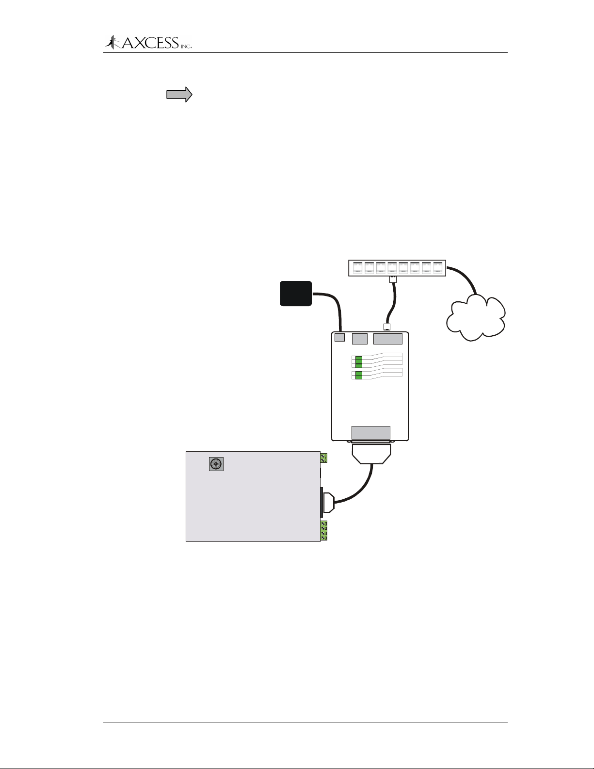
Connecting to the NIU and the Network
IMPORTANT!
connecting them.
Power down the NIU and the Receiver before
Installing the Receiver
Step 1:
Step 2:
Step 3:
Using a DB-25 to DB-9 cable, plug the DB-9 connector into
the RS-232 port on the Receiver. Plug the DB-25
connector into the DB-25 port on the NIU (Figure 22).
Connect the NIU to a hub on your LAN with an RJ-45 to
RJ-45 cable.
Power up the NIU. Upon power up, the NIU sends
information through its serial port that can modify the
settings of the Receiver. Wait 1 minute before powering up
the Receiver so that the Receiver does not receive the
serial data from the NIU.
Hub
RJ-45 to
RJ-45 cable
(Not
Power
Supply
supplied)
6VDC
RESET
10/100
POWER
LINK
100
OK
SERIAL
NIU
Network Interface Unit
ETHERNET
Network or
Internet
Connection
SERIAL
Straight-through serial
cable
RS-232
Figure 22 NIU – ActiveTag Receiver connections
© 2001, AXCESS Inc. 750.001.004 R0033 51

Installing the Receiver
Mounting the Receiver
For best results, the Receiver should be within 35 feet of an activated
Tag.
The receiving antenna should not be blocked by metal or brick.
The following diagrams show various mounting positions for the
Receiver. Two mounting holes on the bottom of the Receiver can be
used to mount the Receiver to a wall (Figure 23). Double-sided tape
can also be used to mount the Receiver. The receiving antenna can
be placed through acoustic tile in a ceiling (Figure 24).
Preferred
mounting
position
2nd choice 3rd choice
Mount with
tape
L Connector
Figure 23 Receiver wall mount positions
IMPORTANT!
If an L connector is used, the receiving antenna must
be positioned as shown in Figure 23, away from the Receiver.
Preferred
mounting
position
2nd choice
Figure 24 Receiver ceiling mount positions
52 750.001.004 R0033 © 2001 AXCESS Inc.

Installing the Receiver
Mounting the Receiving Antenna Separately
In some installations, such as vehicle applications, it may be
necessary to mount the receiving antenna separately from the
Receiver. Detaching the receiving antenna allows you to place the
antenna closer to activated Tags and to place the Receiver in a more
advantageous location, such as an electrical closet or inside a
waterproof enclosure.
AXCESS Inc provides a ground plane bracket for such applications
(Figure 25).
Figure 25 Receiving antenna ground plane
IMPORTANT!
The receiving antenna should be no more that 25 feet
by cable run from the Receiver.
Step 1:
Cut the coaxial cable with sufficient length to connect the
receiving antenna to the Receiver. The cable length should
not exceed 25 feet.
Step 2:
Step 3:
Step 4:
Attach BNC connectors to both ends of the cable.
Remove the receive antenna from the Receiver.
Connect one end of the cable to the receive antenna
connector on the Receiver.
Step 5:
Connect the receiving antenna to the top of the ground
plane bracket and the other end of cable to the bottom of
the connector. If installed outdoors, ensure that there is a
drip-loop in the RG-58 cable below the receiving antenna.
Step 6:
Position the receiving antenna and ground plane as close
as possible to the area where tags are activated.
Drip Loop
Step 7:
The ground plane can be mounted in a variety of positions
on walls or poles using the mounting holes and hardware
provided.
© 2001, AXCESS Inc. 750.001.004 R0033 53

Installing the Receiver
54 750.001.004 R0033 © 2001 AXCESS Inc.

Road Loop Antenna Installation
Introduction
The Road Loop Antenna is designed for vehicle applications. Road
Loop Antenna wire is available in lengths that will accommodate
roadways or gate entrances up to 36-feet in width. For antennas
wider than 36 feet, contact AXCESS Inc. Customer Support at 800577-6080.
The Figure 26 shows a simplified diagram representing the field
generated by a Road Loop Antenna. In reality, antenna fields are
lobed and asymmetrical, but the longest range will still be along the
longest sides. If you are installing a Road Loop Antenna in a multilevel parking garage, keep in mind that the field extends up and down
from the Road Loop.
Antenna fields are affected by the type of pavement, amount of rebar,
and nearby power lines. For these reasons,
recommended that the Road Loop be laid out and tested before
it is permanently mounted
.
it is strongly
Figure 26 A Road Antenna transmit field.
© 2001, AXCESS Inc. 750.001.004 R0033 55

Road Loop Antenna Installation
Required Materials
IMPORTANT!
installation of the Road Loop Antenna:
• Chalk for marking antenna placement
• Concrete nails or duct tape for holding antenna wire down during
initial placement
• Multimeter for continuity check
• A saw for cutting the road surface
• Two 1/8” saw blades with spacer, either abrasive (for asphalt) or
diamond (for concrete)
• A 3 ¼” x 3 ¼” x 4 ½” triangular wood template for cutting corners
(described later in the chapter)
• Vacuum or compressed air for cleaning the cut
• A thin dowel for pressing the Road Loop antenna into the cut
• Road sealant - AXCESS recommends Bondo Flexible
Embedding Sealer (P-606). As a substitute, you can use either 3M’s Detector Loop Sealant or Q-Seal sealant.
Have the following materials on hand for the
IMPORTANT!
To ensure proper system operation, do not substitute
antenna kit components. Road Loop Antenna wire must be ordered
in specific sizes.
Prerequisite Tasks
The following tasks need to be completed before proceeding with the
Road Loop Antenna installation:
!
If applicable, the
installed
. If not, refer to the Original Equipment Manufacturer’s
Wiegand or other controller has been
(OEM) manuals.
!
Ensure that there is no power-line interference directly under the
road surface.
IMPORTANT!
Before permanently installing the Road Loop Antenna,
lay out and test the entire ActiveTag system.
Road Loop Layout & Connecting to the Activator
Step 1:
An AXCESS Inc. RFID tag will be activated and read when
it is over the Road Loop, however it may take a second or
two for the controller to process the Tag information and
activate the gate motor.
Step 2:
If there is a safety loop for the gate, do not use the safety
loop’s cut for the Road Loop Antenna. If the Road Loop
Antenna and the safety loop are installed together, there
56 750.001.004 R0033 © 2001 AXCESS Inc.

Activator
Dimension B
4 feet
Max lead-in wire length:
2
0 feet
Direction
of traffic
Road Loop Antenna
Dimension A
Minimum distance from safety loop:
4 feet
Road Loop Antenna Installation
will be interference and neither is likely to operate properly.
Place the loops at least four feet apart whenever possible.
Receiver
Maximum distance
between receiving
antenna and
activated Tag:
35 feet
Minimum distance
between the Receiver
and ground surface:
4 feet
Safety Loop
Step 3:
Step 4:
Step 5:
Figure 27 Road Loop Antenna installation diagram
Mark the outline of the antenna (yellow contractor’s
crayon, chalk, etc.). Ensure that the corners are 90
degrees.
The long sides (Dimension A, Figure 27) will be shorter
than the width of the road or lane.
IMPORTANT!
loop antenna should
The short sides (Dimension B) of the road
always
measure 4 feet.
If necessary, drive concrete nails (or similar) into the road
surface at the corners to provide the proper rectangular
shape to the antenna when laying down the wire.
Insert the end of the Road Loop wire at the Activator into
one side of a binding post-to-BNC connector (Figure 28).
Tighten the binding post terminal to secure the lead.
© 2001, AXCESS Inc. 750.001.004 R0033 57

Road Loop Antenna Installation
Figure 28 Attaching Road Loop wire to the post-to-BNC
Road Loop Lead- in
Dual bind ing post-toMale BNC Connector
connector
Do not attach yet
Step 6:
Connect the BNC-end of the Road Loop wire to the BNC
antenna connector on the Activator.
Step 7:
Carefully feed Road Loop wire around the pre-marked
loop drawn on the roadway (Step 3). Secure the wire with
duct tape as you proceed.
IMPORTANT!
The
total
length of lead-in wire between the
Road Loop and the Activator must not exceed 20 feet.
Keep twist in the wires to a minimum as you run them from
the Road Loop to the Activator.
Step 8:
At the loop feed point, begin to lay wire around the loop
(using the concrete nails to maintain the corners). Again,
secure the loop to the surface with duct tape.
Step 9:
When back to the feed point, continue around the loop to
complete the appropriate number of wraps according to
the chart below (do not allow the two wires to twist).
Antenna Width
(Dimension A)
4 Feet 36 Feet 2 110 17
4 Feet 34 Feet 2 109 15
4 Feet 32 Feet 2 107 16
4 Feet 30 Feet 2 101 16
4 Feet 28 Feet 2 99 15
4 Feet 26 Feet 3 96 17
4 Feet 24 Feet 3 154 14
4 Feet 22 Feet 3 151 14
4 Feet 20 Feet 3 147 14
4 Feet 18 Feet 3 138 13
4 Feet 16 Feet 3 130 17
4 Feet 14 Feet 4 130 19
4 Feet 12 Feet 4 173 17
4 Feet 10 Feet 4 154 15
4 Feet 8 Feet 4 122 16
4 Feet 6 Feet 4 110 15
Antenna Length
(Dimension B)
Number of
Wraps
Inductance in
Microhenrys (uH)
Min Wakeup
Range (ft)
58 750.001.004 R0033 © 2001 AXCESS Inc.

Road Loop Antenna Installation
Each combination of loop-width, loop-length and wraps of
wire will produce a specific antenna inductance ( measured in Microhenrys) – providing maximum power to the
antenna. But, more wraps than recommended will NOT
produce more range; rather, it will degrade performance!
The “Inductance” column in the chart is included only for
those installers having an inductance meter. If you do not
have an inductance meter, that column is of no value.
Step 10:
Step 11:
Step 12:
Step 13:
After the correct number of loops (see above) have been
completed, continue to lead the wire back to the Activator.
Again, keep twist to a minimum.
Carefully review the installation to this point. If everything
is correct, cut away the excess wire, trim and attach the
other end of the Road Loop wire to the other half of the
binding-post-to-BNC connector (Figure 29).
Road Loop Lead-in
Dual binding post-toMale BNC Connector
Figure 29 Post to Male BNC Connector
Cycle the power of the Activator and check the strength of
the TX Output LEDs.
Using an LED Test Tag, ensure that the activation field of
the Road Loop extends adequately for desired coverage
from the center of the Road Loop (Figure 26). Antennas
with greater width (dimension A) have larger fields.
Step 14:
After ensuring proper operation, remove the wire loop and
concrete nails to allow cutting the groove into the roadway.
Installing the Road Loop Antenna (Frequently contracted)
A normal antenna installation should take about two hours using a
walk-behind concrete saw with an abrasive blade to cut asphalt. Two
1/8" blades with a spacer will be required.
The same antenna should take about three hours to cut in concrete
using a diamond cut blade. Two 1/8" blades with a spacer will be
required.
Step 1:
Step 2:
© 2001, AXCESS Inc. 750.001.004 R0033 59
Confirm that the loop is correctly marked on the road
surface.
Lay out the 45-degree corner cuts. It is helpful to create a
template with the dimensions 3¼” x 3¼” x 4½” (Figure 30).

Road Loop Antenna Installation
3 ¼
i
n
c
h
es
4 ½ inches
Figure 30 Plywood corner template
Do NOT intersect
these cuts!
4 ½ inch side of
plywood template
Saw cuts
Figure 31 Using the template to mark corner cuts
Step 3:
Step 4:
At the corner closest to the Activator, mark a lead-in cut.
Cut a groove that is at least a ¼” wide with the concrete
saw. Set the cutting depth to a minimum of 2” deep.
IMPORTANT!
sawing. You could cut out a chunk of pavement!
When sawing the corner cuts, cut approximately 1” to 1½”
past the loop sides. This will maintain the saw cut depth at
the 45-degree turn.
Step 5:
Thoroughly clean out the groove with a vacuum or
compressed air.
Step 6:
Insert the loop and lead-in into the cut grooves.
use a metal object to push the antenna loop into the saw
cut as it may damage the wire. A tongue depressor or
pencil eraser works well.
Step 7: IMPORTANT!
the strength of the TX Output LEDs.
Step 8:
Step 9:
Test the system.
Dress and/or tie-wrap all cables and seal all exterior BNC
connections with rubber silicone sealant.
Step 10:
Seal the cut with an antenna loop sealant, for example,
Bondo Flexible Embedding Sealer (P-606), 3M Detector
Loop Sealant or Q-Seal sealant. It takes about a gallon of
“Bondo” to seal the cuts from a 16-foot antenna.
Do not let the corners intersect when
Do not
Cycle the power of the Activator and check
60 750.001.004 R0033 © 2001 AXCESS Inc.

Bar Antenna Installation
Introduction
The Bar Antenna typically receives signals transmitted by personnel
and asset Tags (transponders). The Bar Antenna is an excellent
antenna for mounting above or beside a doorway (sometimes above
the ceiling tile) to monitor or control access to an entry/exit point of a
facility.
Antennas of this type radiate RF energy most efficiently in a direction
broadside to the antenna – and radiating less energy off the edges
(Figure 32). Partial rotation of the antenna forward or backward, and
from side-to-side will produce noticeable results.
Direction of
maximum
signal radia tion
To ensure proper system operation,
components.
Prerequisite Tasks
IMPORTANT!
and test the entire ActiveTag system.
Installation Considerations
Determine the
the following guidelines:
• Figure shows different mounting positions for the Bar Antenna.
Try each one before permanently mounting.
Wall
Edge View of Bar
Antenna
Figure 32 Bar Antenna signal radiation
do not substitute antenna
Before permanently installing the Bar Antenna, lay out
approximate
installation site of the Bar Antenna. Use
© 2001, AXCESS Inc. 750.001.004 R0033 61

Bar Antenna Installation
• The Bar Antenna should be within 50 feet (cable length) of the
Activator.
• The Bar Antenna should be located at least 4 inches from any
metal.
Bar Antenna
Bar Antenna
Positions
Positions
4th Choice
4th Choice
1st Choice
1st Choice
2nd Choice
45
45
e
e
c
c
i
i
o
o
h
h
C
C
d
d
r
r
3
3
Figure 33 Installation points for the Bar Antenna
• Orient the Bar Antenna so that the wake-up field provides
maximum coverage of the access or monitoring area (door), etc.
Keep in mind what will be tracked with the antenna – personnel
would carry Tags in their shirt or pants pocket, Tags on laptops
would be carried closer to the floor.
IMPORTANT!
Bar Antenna may also improve performance.
62 750.001.004 R0033 © 2001 AXCESS Inc.
Test each position shown in Figure 33. Tilting the

If mounting the Bar Antenna on the ceiling, mount it flat with the
front of the case pointing at the floor.
• If applicable, follow the guidelines in the manufacturer’s
documentation for placement and wiring of any controller or
peripheral device.
Installing the Bar Antenna
Step 1:
Bar Antenna Installation
Measure the cable run distance between the Activator and
the Bar Antenna and cut a length of RG-58/U coaxial
cable.
Step 2:
Step 3:
Step 4: IMPORTANT!
Step 5:
Step 6:
Step 7:
Attach the BNC connectors to each end of the cable.
Connect one end of the cable to the female BNC
connector labeled
connect the other end to the BNC connector on the
Activator.
Note: Although the Bar Antenna has an RX connector, it is
not used for an ActiveTag installation.
Note: Do not dress-wrap or tie-down the cables until the
antenna has been permanently installed and the system
has been tested.
the strength of the TX Output LEDs.
Test various Antenna locations by positioning the LED
Test Tag at strategic points, i.e., along the edges of the
doorway, along the floor – ensuring complete coverage of
the doorway or monitoring zone.
Attach the open Bar Antenna base to wall using supplied
anchors and screws. If you want to install the Bar Antenna
at an angle, wood wedges or flexible metal brackets can
be used.
Place the plastic cover over the base and align holes on
the sides of the case and cover.
TX
on the back of the Bar Antenna and
Cycle the power of the Activator and check
Step 8:
Step 9:
Step 10:
Step 11:
© 2001, AXCESS Inc. 750.001.004 R0033 63
Insert the rivet bases through aligned holes.
Insert plastic screws into the rivet bases and push until the
screws are tight.
Tighten the screws with a hand-held screwdriver.
The plastic rivets are removable with a screwdriver if it is
ever necessary to open the Bar Antenna case.

Bar Antenna Installation
64 750.001.004 R0033 © 2001 AXCESS Inc.

Picture Frame Antenna Installation
Introduction
A Picture Frame Antenna allows you to mount an antenna in plain
sight without detracting from office surroundings. In a Picture Frame
Antenna, the transmitting and receiving antennas are built into a
picture frame. You can place a picture of your choosing in the frame
and hang the Antenna on the wall near the access or monitoring
point.
Prerequisite Tasks
IMPORTANT!
Antenna, lay out and test the entire ActiveTag system.
Installing the Picture Frame Antenna
Step 1:
Before permanently installing the Picture Frame
Cut the coaxial cable with sufficient length to connect the
Picture Frame Antenna to the Activator. The cable length
should not exceed 50 feet.
Step 2:
Step 3:
Step 4: IMPORTANT!
Step 5:
Step 6:
Step 7:
Attach BNC connectors to both ends of the cable.
Attach the TX connector on the back of the Picture Frame
Antenna to the BNC connector on the Activator.
Note: Although the Picture Frame Antenna has an RX
connector, it is not used in an ActiveTag installation.
the strength of the TX Output LEDs.
Position the antenna in its approximate final location – but
do not permanently install it at this time. Have a helper
hold the antenna in various positions until maximum
coverage is achieved.
Test the system by positioning the LED Test Tag at
strategic points to ensure complete coverage. It will light
up and flash when it is within the field.
Permanently mount the Picture Frame on the wall using
the mounting holes at the bottom and top of the frame and
dress/tie-wrap all cabling.
Cycle the power of the Activator and check
© 2001, AXCESS Inc. 750.001.004 R0033 65

66 750.001.004 R0033 © 2001 AXCESS Inc.

Tags
Types of Tags
LED Test Tag
The LED Test Tag allows you to verify proper system operation and
to detect the presence of an activation field or RF interference.
Personnel Tag
The Personnel Tag’s communications are optimized for multi-Tag
reads. The Tag case is recessed for flush mounting of a personalized
PVC card and has a slot for a clip, lanyard, etc.
Personnel Tag with Panic Alarm
The Personnel Tag with panic alarm is the same as the Personnel
Tag except it transmits a duress signal when a pressure switch
beneath the PVC card is pressed.
Asset Tag
The Asset Tag is the same as the Personnel Tag except it does not
have a slot or PVC card recess.
Asset Tag with Tamper Detect
The Asset Tag with tamper detect is the same as the Asset Tag
except it transmits an alarm signal upon tampering/removal.
Tampering with or removing the Tag from the asset will cause the
Tag to emit an alarm code.
Vehicle Tag
The Vehicle Tag is the same as the Personnel Tag except its
communications are optimized for high-speed reads. The Vehicle
Tag does not have a PVC card recess.
Clicker Tag
The Clicker Tag will transmit its ID and an Activator ID of 127 when it
is pressed. It can also be activated by an activation field.
Harsh Environment Vehicle Tag
Same as the Vehicle Tag except longer operating life (5-7 years) and
greater range of operating temperatures (-40 to +185 F)
© 2001, AXCESS Inc. 750.001.004 R0033 67

Tags
Tag Labeling
Metal Mount Equipment Tag
Same as the Harsh Environment Tag except its robust design is
suitable for exterior mounting direct to metal surfaces. It attaches to
metal using screws or rivets through two 1/8" mounting holes. The
Metal Mount Tag does not have an LED.
The Tag is labeled on its beveled edge. The format for labeling is as
follows:
FCCID:N6E-132-TAG VnnYYMXXTTTTT
where:
FCCID:N6E-132-TAG
Vnn
YY
M
XX
TTTTT
FCC information
Tag version
Last two digits of the year of manufacture.
Month the Tag was made. A, B and C
represent October, November and
December, respectively. Other months are
represented by standard numeric
convention (1 for January, etc.)
Site code, in hexadecimal format. At
present, this value is 19 for site code 25.
Factory ID, a unique preprogrammed ID
number that is stored permanently in the
Tag.
Note: The actual ID number may vary for
custom programmed Tags. The custom ID
number, if any, will be printed on the other
beveled edge.
68 750.001.004 R0033 © 2001 AXCESS Inc.

The LED Test Tag
The LED Test Tag indicates the presence of an activation field or
error condition by lighting LEDs (Figure 34).
Normal
Transmission
Error
Normal
Reception
Tags
If the Test Tag is in a strong activation field, the Normal Reception
LED will flash. The Normal Transmission LED will light with the
sending of Tag data. The Error LED will flash or remain on if the
activation field is not optimized or if the Activator ID is not clear. A
steady flashing at the edge of an activation field is normal – this
indicates that the field is dropping off.
Mounting Tags to Assets
Note: Only an extreme level of prevention is a guarantee against loss
or damage at the hands of a determined thief. However, when assets
are tagged as described here, they will remain tagged for tracking
purposes even under heavy industrial or business usage.
Required Materials
• LED Test Tag
• Mounting materials for asset Tags – cyanoacrylate (ProCement
from ProTec Technology, Super Glue), MEK (methyl ethyl
ketone), double-sided tape, or a Mylar enclosure that has a sticky
back
• Latex gloves if you are using one of the above adhesives
Figure 34 LED Test Tag
• Washable marker or pencil
© 2001, AXCESS Inc. 750.001.004 R0033 69

Tags
IMPORTANT!
vendor’s instructions and the compound’s Material Safety Data
Sheet.
For all assets, mount the Asset Tag with the flat side attached to the
asset.
Testing Mounting Positions
Some electronic devices (for example, laptop computers) generate
radio frequency emissions (noise) that may activate Tags, causing
them to transmit. This unintended activation and transmission could
result in unnecessary battery drainage.
Use the following procedure for mounting a Tag to a laptop:
Step 1:
Step 2:
Step 3:
Step 4:
Step 5:
Before using either cyanoacrylate or MEK, consult the
Turn on the laptop and ensure that the screen is on.
Place the cover in a comfortable working position.
Place the Tag flat side down on the outside of the laptop
cover.
Observe the Tag’s LED as you slide it on the laptop cover
– find a location that does not activate the LED.
Ensure that when the Tag is mounted, it will not interfere
with a docking station.
Step 6: IMPORTANT!
Receiver when the laptop is carried normally through the
wake-up field. In addition, place the Tag on the laptop
where it cannot be easily pried off or removed. Do not
place the Tag on a removable surface (i.e., battery cover).
Step 7:
Mounting the Asset Tag with Adhesive
Step 1:
Step 2:
Step 3:
Step 4:
Once a location is found, use a pencil to trace around the
edge of the LED Test Tag.
Use a cyanoacrylate adhesive (for example, ProCement
from ProTec Technology). Practice the following steps with
similar materials of lesser value until the proper amount of
adhesive and application pressure is established.
Closely follow the instructions provided with the adhesive
kit. You may have to lightly sand the surface inside the
marked area if the asset is painted or has a protective
surface applied.
Wearing latex gloves, thoroughly clean the sanded area
with the supplied isopropyl alcohol pad.
Carefully apply adhesive to the back of the Tag that will be
bonded to the asset. Ensure a continuous bead close to
the edge, but not so thick that the excess will ooze beyond
the edge once the Tag is positioned.
Ensure that the Tag can be read by the
70 750.001.004 R0033 © 2001 AXCESS Inc.

Tags
Step 5:
Mounting a Tamper Tag
Tamper Tags have double-sided tape already applied. Be very
careful when permanently mounting the Tag. Moving the Tamper Tag
once it has been mounted will cause the Tag to enter alarm mode.
Step 1:
Step 2:
Mounting Tags to Vehicles
Required Materials
• LED Tag
• Mounting materials – Velcro tape, double-sided tape, Mylar
enclosure
• Washable marker or pencil
Carefully position the Tag onto the marked area of the
asset, applying pressure for the time specified in the
instructions.
Remove the protective tape covering the adhesive on the
back of the Tamper Tag.
Press the Tag firmly to the asset.
Mounting locations
The first choice for mounting a Tag in a vehicle is on the upper left or
upper right side of the back window. Tags should be mounted on the
side that is closest to the receive antenna. It should not be mounted
on defroster wires. The Tag should be mounted at least 2.5 inches
away from top and sides.
Other mounting places include the upper right or left corner of the
windshield, hanging off the rear view mirror, and above either the
right or the left visor.
Testing for the Best Tag Location
This test is primarily for Tags that need to be mounted in the front
windshield area. This test may not be necessary for back window
mounting.
Step 1:
Step 2:
Step 3:
With the car out of range of the Road Loop Antenna, sit in
the car and hold LED test tag five inches from the top and
the side on the window.
Start the car -- while watching the LED to see if it lights.
(Note: this may occur in some vehicles due to alternator
noise.)
If the Tag turns on, move the tag up/right ½ inch and
repeat test until the Tag no longer turns on.
© 2001, AXCESS Inc. 750.001.004 R0033 71

Tags
Step 4:
Step 5:
Mounting a Vehicle Tag
Step 1:
Step 2:
Step 3:
Mark the spot you found on the windshield with some
scotch tape or a washable marker.
Note: The LED light can be hard to see in bright daylight.
Shield the LED with your hand while holding it against the
windshield.
Test the various positions to find the one that works best
for your installation and the vehicles involved.
Apply mounting tape/Velcro on the back of the Tag. Push
the mounting tape/Velcro securely on the back of the Tag.
IMPORTANT!
antenna, the Tag must be mounted with the back of the
Tag facing the glass at least 3 inches from the dashboard.
If using Velcro, apply one side of the Velcro mount to the
location where the LED Tag was successfully tested. Then
mount the Tag with the other piece of Velcro onto the
Velcro on the windshield.
If using double-sided tape, peal the cover off the doublesided tape attached to the Tag. Firmly apply the Tag to the
windshield location you found earlier and press the Tag to
the windshield ensuring solid contact.
To receive maximum range from the
72 750.001.004 R0033 © 2001 AXCESS Inc.

Tags and Personnel
Tags
Required Materials
• Mounting materials – clips, chains, etc.
Personnel Tags can be threaded onto a chain, placed in a pocket, or
hooked on a clip. A picture ID card can fit in the Tag’s recess.
Operating Panic Tags
To send an alarm message, press the button for at least .5 seconds.
The Tag will transmit an alarm code for one minute, then begin to
operate normally in addition to transmitting the alarm code so that it
can be tracked.
The alarm mode can be turned off by pressing the button for three
seconds after the initial one minute of alarm mode. The Tag will reset
in three seconds. The Tag will not broadcast when the button is
pressed or during the reset phase. The Tag can be placed in alarm
mode again after the reset period.
© 2001, AXCESS Inc. 750.001.004 R0033 73

Tags
74 750.001.004 R0033 © 2001 AXCESS Inc.

Appendix A: Troubleshooting the System
Required Materials
The following materials are necessary for troubleshooting:
• LED Test Tag
• A regular Tag
• Tape measure for measuring fields and cable
• A computer for interfacing directly with the Receiver and Activator
– a laptop is ideal
• A terminal emulation application such as HyperTerminal
• A one-to-one serial cable with a DB9 male connector
• Multimeter
Check the Site
Step 1:
Check the cable length – there should be a maximum of
50 feet between the Activator and transmitting antenna. If
the cable is too long, it will need to be shortened.
Step 2:
Step 3:
Check the distance between activated Tags and the
receiving antenna – ensure that the receiving antenna is
within 35 feet of activated Tags.
Ensure that the system is protected from the elements.
Exposed equipment should be waterproofed.
Check the Cables and Connectors
Most of the problems encountered with the ActiveTag system lie with
the cables. This includes having little or no range on the antennas.
Step 1:
Step 2:
Step 1:
Ensure that RG-58/U with 100% foil shield coverage is
used.
Ensure that the connectors are not free spinning. Replace
any connectors on cables that freely spin.
Check the continuity of the cables. There must be
continuity from end of the cable to the other (center
conductor) but
Check the Activator
Step 1:
Test the range of the activation field with the LED Test Tag
and compare it to the range listed Appendix E:
Specifications, page 87.
no
continuity between center and braid.
© 2001, AXCESS Inc. 750.001.004 R0033 75

Appendix A: Troubleshooting the System
Step 2:
Step 3:
If the activation field is smaller than desired, cycle the
Activator’s power and check the TX Output LEDs. Also,
ensure that the activation field is turned up. See the
section
If the activation field is larger than desired, then the field
needs to be adjusted. See the section
Activation Field
Check the Transmitting Antenna
Road Loop
Step 1:
Step 2:
Step 3:
Step 4:
Ensure that there is not a splice in the Road Loop
Antenna.
Test a Road Loop Antenna for continuity across the ends
of the lead wires. If continuity does not exist, there is a
problem with the Road Loop wire.
Connect the Road Loop Antenna leads into the BNC-todual-binding-post adapter for continuity. If continuity does
not exist, the adapter is faulty. Replace the adapter.
Ensure that the layout of the system is within
specifications:
Resizing the Activation Field
, page 32.
, page 32.
Resizing the
The loop layout 4 feet x ordered width. The Road Loop
should be installed on the right side of the lane and the
longest length should go across the width of the lane.
Number of wraps appropriate for the length of the antenna.
See the section
for further information on wrapping the Road Loop.
Step 5:
Step 6:
Step 7:
Bar and Picture Frame Antennas
Step 1:
Step 2:
Step 3:
Ensure that the Road Loop is laid out correctly in the lane
– the longest side should go across the width of the lane.
Ensure that the Road Loop is installed on the right-hand
side of the lane.
Reduce the activation field. See the section Resizing the
Activation Field, page 32.
Ensure that the Activator is connected to TX connector on
the antenna.
Ensure that the antenna has been positioned correctly.
The Bar and Picture Frame Antennas are for indoor use
only.
Ensure the TX CTRL on the Activator is turned to
maximum. See the section Resizing the Activation Field,
page 32.
Road Loop Antenna Installation,
page 55,
76 750.001.004 R0033 © 2001 AXCESS Inc.

Check the Tags
Ensure that the Tags are properly mounted. Tags should not be
mounted in an area that can wake them up when they are not in the
antenna field. They should be mounted in such a way that they can
be activated when they enter the antenna field.
If the Tags are mounted on vehicles, ensure that they are beige.
Black Tags become hotter than beige Tags in direct sunlight and can
warp under extreme conditions.
Check the Reception
If the wake-up field is functioning but Tags are not being read, then
there may be a problem with the reception portion of the system.
Appendix A: Troubleshooting the System
Step 1:
Step 2:
Ensure that the Receiver has power.
Ensure that the tag is programmed into the system if
appropriate – i.e., for Wiegand control panels.
Check the Output and Connections to Third-Party Devices
Serial
Step 1:
Step 2:
Step 3:
Wiegand
Step 1:
Step 2:
Step 3:
Ensure that the RS-232 cable is properly seated.
Ensure that the Receiver has power.
Ensure that the communications port settings on the serial
device are correct: that the baud rate matches the rate the
Receiver has been programmed with, eight data bits, no
parity, one stop bit, no flow control.
Ensure that the Wiegand control panel complies with the
SIA 26-bit standard.
Ensure that Data Zero, Data One and Ground are wired to
the Wiegand control panel correctly.
Ensure that the Tags and site code are entered correctly
into the panel.
Step 4:
© 2001, AXCESS Inc. 750.001.004 R0033 77
Ensure that the data is buffered correctly. See Appendix C:
Advanced Wiegand Configuration, page 81.

Appendix A: Troubleshooting the System
78 750.001.004 R0033 © 2001 AXCESS Inc.

Appendix B: Coaxial Cable
number one problem
The
technique and connectors. Ensure that no stray braid wires are
touching the center contact pin when pushing it into the connector.
This may cause the equipment to function intermittently or with
reduced range. Good wiring techniques will eliminate considerable
troubleshooting time later in the installation.
Required Materials
• RG-58/U coaxial cable with 50-ohm impedance (nominal), solid
copper center conductor, 55% tinned copper braid or better,
100% foil shield coverage (for example, Belden 9310).
• 3-blade rotary coaxial cable stripper
• 3-piece crimp type male BNC connector (for example, Amphenol
31-320). Screw-on connectors are
short to ground easily and can be pulled apart.
• Diagonal cutters
• BNC crimpers
• Multimeter with continuity check
encountered during installation is wiring
NOT
recommended. They
Attaching the BNC Connector
Step 1:
Step 2:
Step 3:
Step 4:
Step 5:
Step 6:
Step 7:
Step 8:
Cut RG-58/U coaxial cable and trim jacket.
Slip the crimp sleeve over the cable. Place the contact pin
onto the inner conductor. The end of contact and insulator
must be butting and square.
Ensure that the pin goes to center, braid to shield
Crimp with appropriate tooling.
Flare the outer braid and gently but firmly push the contact
into the connector housing until a gentle snap is felt,
indicating the contact is in place.
Slip the crimp sleeve in place, butting the flange against
the connector body.
Crimp with the appropriate tool.
Test for continuity of the inner conductor from connector to
connector. Test for continuity between connectors. Test for
insulation between inner conductor and connectors.
© 2001, AXCESS Inc. 750.001.004 R0033 79

Appendix B: Coaxial Cable
Coaxial Cable
11/3211/32 3/16
1/8
Inner Conductor
Braid
Sleeve
Insulator
Inspection Hole
Crimp Area
Contact Pin
Butting Flange
Crimp
Area
Plug Body
Assembly
Figure 35 Dimensions for Coaxial Cable Termination
80 750.001.004 R0033 © 2001 AXCESS Inc.

Appendix C: Advanced Wiegand Configuration
Data Buffering
Setting the Time between Outputs
By default, the Receiver sends Tag data every 1.3 seconds.
Depending on your control panel, you may need to change the
interval between data outputs. Your panel may be able to accept data
faster than once every 1.3 seconds, or it may need a longer interval
between outputs.
To change the interval between Tag outputs, type a number followed
by a capital T. This number is the time in tenths of a second that the
Receiver will wait between Tag outputs. Valid numbers are between
0 and 255. For example, if you want the Receiver to wait 2 seconds
between Tag outputs, type the following:
20T
20T
20T20T
Changing the Duplicate Tag Buffer
Once a Tag is reported, its information is stored in the Receiver’s
buffer for 12.5 seconds. During which time, the Receiver will not
report duplicate information for that Tag. After 12.5 seconds, if the
Tag’s transmission is still being received, the Tag will be reported
again. If more than ten Tags are received in the 12.5 seconds, the
earliest Tag information is overwritten by new Tag data.
To change the length of time that Tag data will remain in the
duplicate buffer, type a number between 0 and 255 followed by a
capital L:
<number>L
<number>L
<number>L<number>L
This number is the time in tenths of a second that a particular Tag's
entry will remain in the duplicate buffer.
For example, if you want the Receiver to wait five seconds before
transmitting duplicate information, type:
50L
50L
50L50L
© 2001, AXCESS Inc. 750.001.004 R0033 81

Appendix E: Speci fications
82 750.001.004 R0033 © 2001 AXCESS Inc.

Appendix E: Speci fications
Appendix D: Receiver Commands
Network Receiver Commands
All commands issued to the Network Reader are preceded by a numeric entry followed by an
alpha character. Any command that is not preceded by a numeric entry will be ignored.
The 'c' command set is used for all commands that do not require entry of a specific numeric
value, such as setting a specific configuration attribute ON or OFF. The format for ‘c’
commands is
the specific action to be taken by the Receiver. For example, the command “15c” sets the
Wiegand output flag to ON, and “29c” sets Wiegand output to OFF.
In addition to ‘c’, there are additional commands that allow the user to input specific values for
certain attributes of the Receiver. The format for these commands is
where <number> is the three-digit ASCII number for the input value and <character> is an
ASCII letter or symbol that determines the specific attribute to be modified in the Receiver.
For example, the command
<number> value must be within the range specified for each command in order to be valid.
The commands supported by the Network Receiver are as follows:
<code>c
where <code> is a two digit numeric command code that determines
<number><character>
<number>
I
is used to set the Receiver’s Device ID. The
Global Configuration and Output Control
<number>I set Device ID for Network Receiver; valid numbers = 0 thru 999 (default = 001)
20c set Wiegand/TTL interrupts to ON; i.e. enable Wiegand/TTL capabilities (default)
35c set Wiegand/TTL interrupts to OFF; i.e. disable Wiegand/TTL capabilities
(Note: Setting Wiegand/TTL interrupts to OFF via command 35c maximizes the speed at
which tag read data will be processed and output over a serial or TCP/IP connection.)
22c set serial diagnostics output to OFF; i.e. output tag data per configuration settings
(default)
39c set serial diagnostics output to ON; i.e. output tag read data in diagnostic format
38c return and display current configuration information; i.e. Device ID, Valid ID list, and
configuration settings/values
40c output Supervisory “ping” response; i.e. receiver’s Device ID and firmware version
Configure/Control Serial Output
23c set serial data rate to 4800 baud
24c set serial data rate to 9600 baud (default)
25c set serial data rate to 19200 baud
18c set tag read serial output to ON; i.e. output tag read data (default)
32c set tag read output to OFF; i.e. disable tag read data output
21c set serial output to the long format RRRAAAFFFTTTTT (default)
where RRR = Receiver ID, AAA = Activator ID or Status Code, FFF = Facility Code, TTTTT =
Tag ID
36c set se rial output to short format AAAFFFTTTTT
where AAA = Activator ID or Status Code, FFF = Facility Code, TTTTT = Tag ID
© 2001, AXCESS Inc. 750.001.004 R0033 83

Appendix E: Speci fications
Configure/Control Wiegand Output
15c set Wiegand output to ON; i.e. report tag read data via Wiegand port (default)
29c set Wiegand output to OFF
<number>W set single valid Wiegand Activator ID; valid numbers = 1 thru 250 (default = 127)
<number>L set tag redundancy buffer time in tenths of seconds; valid numbers = 0 thru 255
(default = 125 or 12.5 seconds)
<number>T set time between tag read outputs in tenths of seconds; valid numbers = 0 thru
255
(default = 13 or 1.3 seconds)
19c set Wiegand Activator ID filter to ON, i.e. output only tag data valid per the Wiegand
Activator ID as set by the <number>W command (default)
33c set Wiegand Activator ID filter to OFF, i.e. outputs all tag reads validated by both the Wiegand
Activator ID and the Valid ID list
12c set Wiegand alarm output to OFF; i.e. do not output data if Status Code = 000 (default)
26c set Wiegand alarm output to ON; i.e. output tag data when Status Code = 000
(Note: The Wiegand filters, buffers and settings do not affect the serial output. Unless Wiegand output
is set to ON via command 15c, no data will be output via Wiegand regardless of the other settings.)
Configure/Display Valid ID List
<number>+ add new Device ID or Status Code to Valid ID list; valid numbers = 0 thru 255
(Note: maximum of 34 entries in Valid ID list)
<number>- delete a Device ID or Status Code to Valid ID list; valid numbers = 0 thru 255
(Note: Valid ID list must have a minimum of one entry)
34c set Valid ID list to default values; i.e. V5 Activator IDs and Status Codes (default)
37c clear Valid ID list; i.e. delete all IDs/Codes from 000 to 255 except 127 (Note: List cannot be
empty)
38c return and display current configuration information; i.e. Device ID, Valid ID list, and
configuration settings/values
Configure/Activate TTL output Control
10c turn on TTL output 1 now
11c turn on TTL output 2 now
13c set TTL output 1 alarm flag to OFF; i.e. do not turn on TTL output 1 if Status Code = 000
(default)
27c set TTL output 1 alarm flag to ON; i.e. turn on TTL output 1 if Status Code = 000
14c set TTL output 2 alarm flag to OFF; i.e. do not turn on TTL output 2 if Status Code = 000
(default)
28c set TTL output 2 alarm flag to ON; i.e. turn on TTL output 2 if Status Code = 000
16c set TTL output 1 valid read flag to OFF; i.e. do not turn on TTL output 1 on valid tag
read (default)
30c set TTL output 1 valid read flag to ON; i.e. turn on TTL output 1 on valid tag read (per the
Valid ID list)
17c set TTL output 2 valid read flag to OFF; i.e. do not turn on TTL output 2 on valid tag
read (default)
84 750.001.004 R0033 © 2001 AXCESS Inc.

Appendix E: Speci fications
31c set TTL output 2 valid read flag to ON; i.e. turn on TTL output 2 on valid tag read (per the
Valid ID list)
<number>D set control TTL output 1 signal duration time in seconds; valid numbers = 0
thru 255
(default = 5 seconds)
<number>E set control TTL output 2 signal duration time in seconds; valid numbers = 0
thru 255
(default = 5 seconds)
Network Receiver Command Responses
The response to a command will be either a two-digit response code or the specific
information requested by a query command. Due to the limited processing capability of the
Receiver, the application software (ActiveTrac) manages the process as follows:
(a) buffers all outgoing commands;
(b) sends commands one at a time (minimum 100 ms delay between commands);
(c) confirms responses; and
(d) resends commands if no response is received within a specified time-out period.
The following set of response codes is output by the Network Receiver to acknowledge
receipt and processing of configuration and control commands:
00 Command completed successfully (ACK)
01 Duplicate Device ID (response for command <number>+)
02 Valid ID list full (response for command <number>+)
03 Valid ID list must contain at least one entry (response for command
<number>-)
04 Device ID not found (response for command <number>-)
05 Invalid entry (response for <number> commands when value entered is not
allowed)
06 Invalid command (response for an invalid or unknown command entry)
The following data is output in response to query and supervisory commands:
38c [Content: Device ID, Valid ID list, configuration settings/values; Format: Refer to
installation manual]
40c [Content: Device ID, firmware version; Format: Refer to installation manual]
© 2001, AXCESS Inc. 750.001.004 R0033 85

Appendix E: Speci fications
Sequential Command List
<number>D set control TTL output 1 signal duration time in seconds (0-255,5)
<number>E set control TTL output 2 signal duration time in seconds (0-255,5)
I
<number>
<number>L set tag redundancy buffer time in tenths of seconds (0-255, 125)
<number>T set time between tag read outputs in tenths of seconds (0-255, 13)
<number>W set single valid Wiegand Activator ID (1-250, 127)
<number>+ add new Device ID or Status Code to Valid ID list (0-255, max 34)
<number>- delete a Device ID or Status Code to Valid ID list (0-255, min. 1 entry)
10c turn on TTL output 1 now
11c turn on TTL output 2 now
12c set Wiegand alarm output to OFF
13c set TTL output 1 alarm flag to OFF
14c set TTL output 2 alarm flag to OFF
15c set Wiegand output to ON
16c set TTL output 1 valid read flag to OFF
17c set TTL output 2 valid read flag to OFF
18c set tag read serial output to ON
19c set Wiegand Activator ID filter to ON
20c set Wiegand/TTL output interrupts to ON
21c set serial output to the long format (RRRAAAFFFTTTTT)
22c set serial diagnostics output to OFF
23c set serial data rate to 4800 baud
24c set serial data rate to 9600 baud
25c set serial data rate to 19200 baud
26c set Wiegand alarm output to ON
27c set TTL output 1 alarm flag to ON
28c set TTL output 2 alarm flag to ON
29c set Wiegand output to OFF
30c set TTL output 1 valid read flag to ON
31c set TTL output 2 valid read flag to ON
32c set tag read output to OFF
33c set Wiegand Activator ID filter to OFF
34c set Valid ID list to default values (per V5 list)
35c set Wiegand/TTL output interrupts to OFF
36c set serial output to short format (AAAFFFTTTTT)
37c clear Valid ID list (except 127)
38c return and display current configuration data
39c set serial diagnostics output to ON
40c return and display Supervisory data
set Device ID for Network Receiver (0-999)
86 750.001.004 R0033 © 2001 AXCESS Inc.

Appendix E: Specifications
Receiver
Dimensions
Height: 1 inch
Width: 4.5 inches
Depth: 5.5 inches
Input Current: 24V DC at 50 mA for Serial Receiver
200 mA for LAN/WAN Receiver
Frequency: Receives at 315 MHz
Connectors
• DB9 Female RS-232 (to the computer/device)
• BNC Female (in from receiving antenna)
• Power terminal block
• Wiegand terminal block
• 2 power jacks (one auxiliary)
Appendix E: Speci fications
Activator
Power
Adapter
110 AC to 4.4V DC - plugs into a 110 AC outlet and supplies 400 mA
of current to power the Receiver.
Input: 120V AC, 60 Hz
Output: 4.4V DC, 400 mA nominal
Dimensions
Height: 1.5 inch
Width: 3.5 inches
Depth: 6.5 inches
Input Current: 24V DC at 700 mA.
Frequency: Transmits at 132 kHz
Connectors
• Female BNC - TX (out to transmitting antenna)
• DB9 Female RS-232 (to the computer/device)
• Power jack
© 2001, AXCESS Inc. 750.001.004 R0033 87

Appendix E: Speci fications
Power
Adapter
110 AC to 24V DC - plugs into a 110 AC outlet and supplies 1 A of
current to power the Activator.
Input: 120V AC, 60 Hz
Output: 24V DC, 1 A nominal
No load: 31.4V DC
Antennas
Road Loop Antenna
Dimensions
Length: 4’ X width of the road loop
Gauge: 18
Weight: Approx. 1 lb per 10 feet of wire
Frequency: Transmits at 132 kHz
Coverage: 16 – 24 feet for a single lane 4’ x 16’ loop, can be
greater with larger loops
Connectors
• Dual binding post to male BNC (to Activator)
Bar Antenna
Dimensions
Length: 38 inches
Width: 5 inches
Depth: 1 inch
Weight: 2.3 pounds
Frequency: Transmits at 132 kHz
Coverage: 8 –12 feet typical (typical)
Connectors
• Terminal - TX (to Activator)
88 750.001.004 R0033 © 2001 AXCESS Inc.

Tag
Appendix E: Speci fications
Picture Frame Antenna
Dimensions
Standard: 16” x 20” x 2”
Weight: 6.7 pounds
Coverage: 8 feet (typical)
Large: 20” x 26” x 2”
Weight: 8.1 pounds
Coverage: 10 feet (typical)
Frequency: Transmits at 132 kHz
Connectors
• Female BNC - TX (to Activator)
Personnel Tag / Personnel Tag with Panic Alarm / Vehicle Tag / Asset Tag / Asset Tag with Tamper Detect
Length: 3.4 inches
Width: 2.2 inches
Thickness: 0.25 inch
Weight: Less than 1 ounce
Operating Life: 3-5 years
Operating Temperature: 0 to +160 F (-20 to +70 C)
Frequency: Transmit: 315 MHz
Receive: 132 kHz
Harsh Environment Vehicle Tag
Length: 3.4 inches
Width: 2.2 inches
Thickness: 0.4 inch
Weight: 1 ounce
Operating Life: 5-7 years
Operating Temperature: -40 to +185 F (-40 to +85 C)
Frequency: Transmit: 315 MHz
Receive: 132 kHz
© 2001, AXCESS Inc. 750.001.004 R0033 89

Appendix E: Speci fications
Metal Mount Equipment Tag
Length: 2 inches
Width: 4 inches
Thickness: 0.5 inch
Weight: 2 ounces
Operating Life: 5-7 years
Operating Temperature: -40 to +185 F (-40 to +85 C)
Frequency: Transmit: 315 MHz
Receive: 132 kHz
90 750.001.004 R0033 © 2001 AXCESS Inc.

Index
A
Activator
Changing ID Number, 24
Connecting to the Road Loop Antenna, 52
Functions, 10
ID Codes, 24
Required Materials, 27
Specifications, 81
Antennas
Functions, 12
Types, 12
B
Bar Antenna, 57
Installation Considerations, 57
Installation Points, 58
Installing, 59
Specifications, 82
C
Cable, 75
Attaching BNC Connectors, 75
Configuration, 21
E
I
Installation, General
Cabling, 18
Tips, 17
R
Receiver
Functions, 11
Specifications, 81
RFID Systems
Components, 9
History, 9
Road Loop Antenna, 51, 72
Connecting to the Activator, 52
Installing, 55
Layout, 52
Specifications, 82
Rood Loop Antenna
Required Materials, 52
S
Safety, 5
Swing Frame Antenna, 61
Installing, 61
Specifications, 83
Equipment, Required, 6
F
Firmware
configuring, 21
H
Hotline, 2
T
Tags, 10
Mounting, 64
Troubleshooting, 71
W
Waterproofing, 17
© 2001, AXCESS Inc. 750.001.004 R0033 91
 Loading...