

Page 1

NT132 RFID System
Installation Manual
Page 2

Notices
Notices
Information provided in this manual is a result of the design and
development of AXCESS
without notice. It applies only to current AXCESS
systems.
No part of this manual may be reproduced, translated or transmitted,
in any form or by any means, without the prior written consent of
AXCESS
Responsibilities
• AXCESSTM INC. declines all liability for any damage that might
• AXCESS
• AXCESS
Registered Trademarks
Product names mentioned herein may be trademarks and/or
registered trademarks of their respective companies.
TM
TM
INC. products and is subject to change
INC.
TM
INC. RFID
result from any errors or omissions in this document or from
improper installation.
TM
INC. can only guarantee the correct operation of its
products if they are used with the software programs, systems,
and consumables supplied or authorized in writing by AXCESS
INC.
TM
INC. recommends keeping the original packaging for
transporting the equipment later.
TM
Document Revisions
Number Changes Author Date
700.001.001 Original Issue Jerry Hegdahl Nov 1998
750.001.002 Update Jean Mahoney Mar 1999
750.001.003 Update Jean Mahoney Apr 1999
750.001.003 Update Jean Mahoney July 1999
Customer Service
AXCESSTM INC. toll-free distributor support hotline is1-800-577-
6080. Representatives are available to answer your questions from
7:30 – 6:30 Central Standard Time.
2 750.001.003
Revised June 1999
© 1999 AXCESSTM Inc.
Page 3

Table of Contents
General Installation Information................................................7
Safety.................................................................................................................................7
Information Flags...............................................................................................................7
Installation Tips..................................................................................................................8
Things to Consider............................................................................................................. 9
Hand Tools, Equipment and Materials.............................................................................10
NT132 System Overview...........................................................13
History..............................................................................................................................13
NT132 System Components............................................................................................ 13
Tags.................................................................................................................................15
Reader.............................................................................................................................16
Antennas..........................................................................................................................17
Antenna Tuning Unit (ATU) .............................................................................................18
Reader Installation....................................................................19
Introduction......................................................................................................................19
Required Materials........................................................................................................... 20
Mounting the Reader - All Types .....................................................................................21
Installation of a Serial Reader..........................................................................................22
Installation of a Wiegand Reader ....................................................................................23
Installation of an FTT Reader System .............................................................................25
Connecting Power to the Reader – All Types..................................................................32
Configuring 3.x Reader Firmware............................................35
Required Materials........................................................................................................... 35
Connecting a Computer to the Reader............................................................................35
Communicating with the Reader via HyperTerminal .......................................................37
Reader Commands ......................................................................................................... 38
Entering a Command.......................................................................................................39
Toggling between reading 3.x Tags and reading 2.0 Tags..............................................40
Changing the Reader ID Number .................................................................................... 41
Toggling Between Default and Diagnostic Modes...........................................................42
Bypass Mode - Enabling Action on 254 Code .................................................................44
Unilon Reset Buttons.......................................................................................................45
Antenna Tuning Unit (ATU) Installation...................................49
Introduction......................................................................................................................49
Installation Considerations...............................................................................................49
Required Materials........................................................................................................... 50
Prerequisite Tasks...........................................................................................................50
Mounting the ATU............................................................................................................51
Cabling the ATU ..............................................................................................................52
Connecting the ATU to the Reader.................................................................................. 53
Connecting the ATU to the Antennas .............................................................................. 53
Page 4

Contents
Dipole Antenna Installation ..................................................... 55
Introduction.......................................................................................................................55
Required Materials...........................................................................................................55
Prerequisite Tasks ...........................................................................................................55
Installing the Dipole Antenna............................................................................................56
Road Loop Antenna Installation .............................................. 59
Introduction.......................................................................................................................59
Required Materials...........................................................................................................60
Prerequisite Tasks ...........................................................................................................60
Road Loop Layout & Connecting to the ATU...................................................................61
Common Layout Problems...............................................................................................63
Installing the Road Loop Antenna....................................................................................64
Bar Antenna System Installation............................................. 67
Introduction.......................................................................................................................67
Required Materials...........................................................................................................68
Prerequisite Tasks ...........................................................................................................68
Installation Considerations ...............................................................................................68
Installing the Bar Antenna ................................................................................................70
Swing Frame Antenna System Installation............................. 71
Introduction.......................................................................................................................71
Required Materials...........................................................................................................71
Prerequisite Tasks ...........................................................................................................71
Installing the Swing Frame Antenna.................................................................................71
Maximizing Antenna Performance w i th the ATU.................... 73
Adjusting Antenna Performance ......................................................................................73
Modifying Antenna Range: Adjusting the Tr ansmi tter Card . 77
Introduction.......................................................................................................................77
Required Materials...........................................................................................................78
Adjusting the Transmission Field.....................................................................................78
Tag Mounting............................................................................ 79
Mounting Tags to Assets..................................................................................................79
Mounting Tags to Vehicles...............................................................................................81
Tags and Personnel.........................................................................................................83
Troubleshooting the System ................................................... 85
Introduction.......................................................................................................................85
Required Materials...........................................................................................................85
Check the Power..............................................................................................................85
Check the Site..................................................................................................................86
Trace the Cables..............................................................................................................86
4 750.001.003
Revised June 1999
© 1999 AXCESSTM Inc.
Page 5

Contents
Check the Connectors ..................................................................................................... 86
Check the Antennas and Cables for Continuity...............................................................87
Check the ATU ................................................................................................................89
Check the Reception .......................................................................................................90
Check the Output and Connections to Third-Party Devices............................................ 91
Common Problems with NT132 Components.........................93
Cable................................................................................................................................93
Power...............................................................................................................................93
ATU..................................................................................................................................93
Road Loop Antenna.........................................................................................................94
Dipole Antenna ................................................................................................................ 96
Bar Antenna.....................................................................................................................96
Swing Frame Antenna ..................................................................................................... 97
Wiegand Reader..............................................................................................................98
Serial Reader...................................................................................................................98
FTT Reader .....................................................................................................................99
Serial Gateway.................................................................................................................99
Tags.................................................................................................................................99
Appendix A: Coaxial Cable.....................................................101
Required Materials......................................................................................................... 101
Attaching the BNC Connector........................................................................................ 101
Appendix B: Specifications .................................................... 103
Reader...........................................................................................................................103
Serial Gateway...............................................................................................................104
Antenna Tuning Unit (ATU) ...........................................................................................104
Antennas........................................................................................................................105
Tag.................................................................................................................................106
Customer Support Questionnaire..........................................107
Index........................................................................................109
© 1999, AXCESSTM Inc. 750.001.003
Revised June 1999
5
Page 6

Page 7

General Installation Information
Safety
• Personal safety is of first importance in the performance of any
job.
• Installation and configuration of the NT132 system should only be
performed by experienced installers.
• Where practical or required by code, all wiring should be
enclosed in conduit, or equivalent protection, firmly anchored to
sturdy structural elements and protected from mechanical
damage.
• Hand tools should be of good quality and properly maintained.
• Hand tools should be used in the applications for which they were
intended.
• Always wear eye protection when using power tools.
• When drilling, cutting or drilling, do not damage wires, pipes or
structural components.
• When installing antennas and related equipment above ceiling,
make sure they are properly attached to a structural member and
accessible for maintenance.
Information Flags
Information Flags draw your attention to important information:
IMPORTANT!
These sections provide information you must have to ensure proper
operation of hardware or software. If this advice is not followed,
system recovery can be difficult or time-consuming. ALWAYS READ
THESE ITEMS.
NOTE
These sections provide helpful information that can make the
installation go more smoothly and quickly.
Page 8
General Installation Information
Installation Tips
IMPORTANT! Bench test communications between the
NT132 system and the controller or device to which it will
be connected.
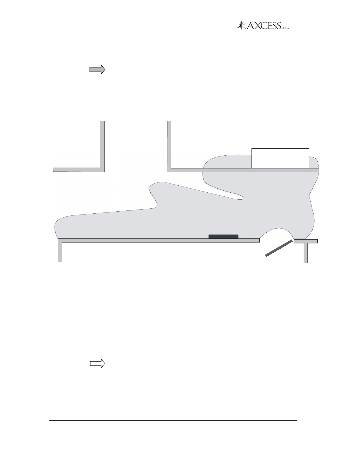
Lay the entire AXCESS NT132 system out and test the
antenna fields before permanently installing any piece of
the system.
Supply Cabinet
Swing Frame Antenna
Figure 1 A real-life example of an antenna field. The gray area is
the field of a Swing Frame Antenna mounted in a hall. Always
test your field to ensure that you get the coverage you want.
Waterproofing
Any parts of the system exposed to the elements must be
waterproofed using sealing tape, waterproof boxes, sealant spray,
etc.
RTV rubber silicone sealant can be used on outside connections to
protect them from the weather.
Note: The silicone seal can be broken by just pulling on a cable, and
the sealant would then need to be reapplied.
8 750.001.003
Revised June 1999
© 1999 AXCESSTM Inc.
Page 9
Things to Consider
General Installation Information
IMPORTANT! The Reader must be installed in a moisture-free
environment at approximately room temperature and a minimum of
36 inches above the floor. Installation at eye height is recommended.
If possible, position the Reader and the ATU where they are not
readily accessible to help prevent tampering or accidental damage.
Cabling
• Use only RG-58/U coaxial cable with 50-ohm impedance
(nominal), solid copper center conductor, 55% tinned copper
braid or better, 100% foil shield coverage (for example, Belden
9310).
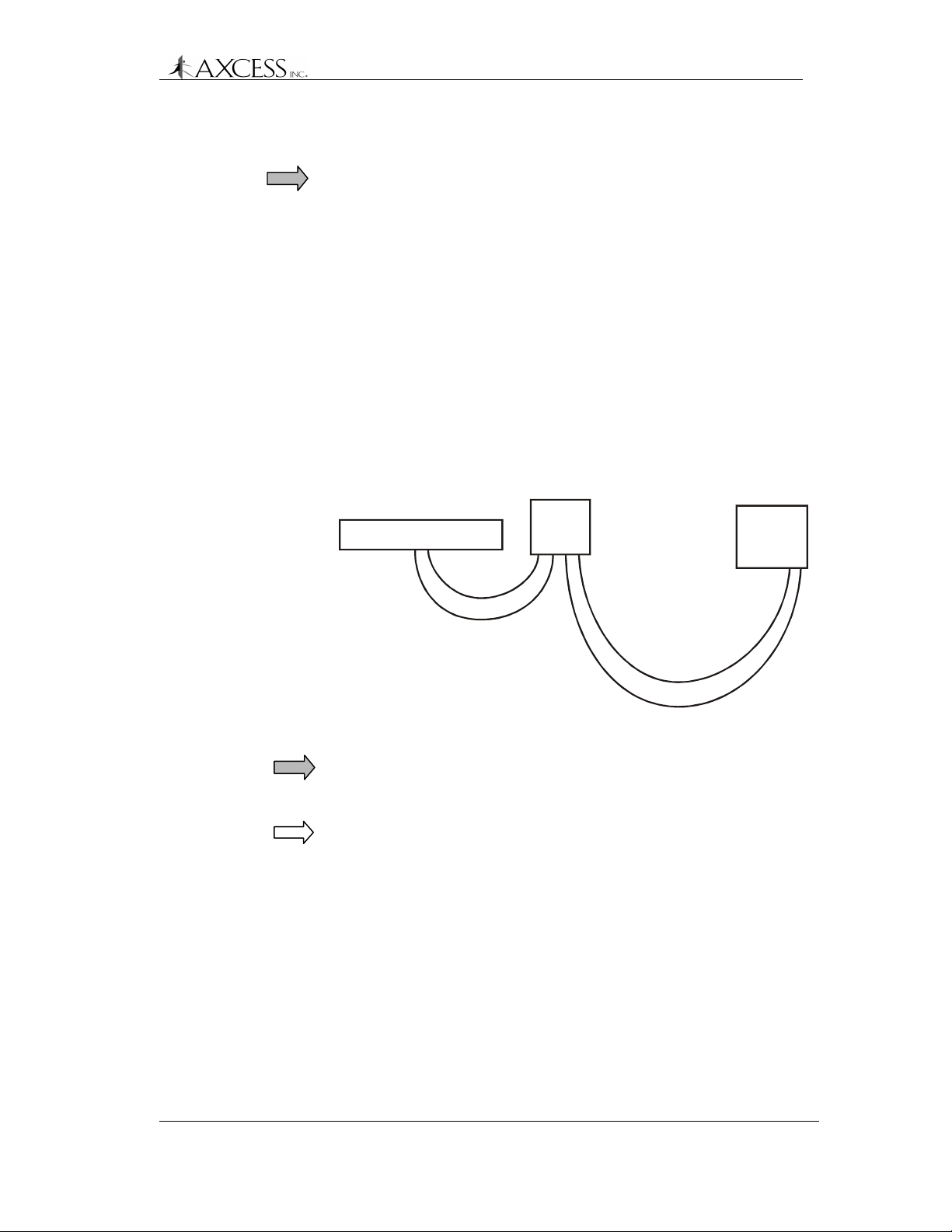
• The maximum recommended cable length between the Reader
and ATU is 80 feet.
• The maximum recommended cable length between the ATU and
the antennas is 20 feet.
Bar Antenna
20 feet
ATU
Reader
80 feet
Figure 2 Maximum recommended cable lengths
IMPORTANT! System performance may be adversely affected if a
different cable is used, the cable lengths exceed recommendations,
or if the cable is kinked.
NOTE: All distances are by cable run unless specified otherwise.
© 1999, AXCESSTM Inc. 750.001.003
Revised June 1999
9
Page 10

General Installation Information
Hand Tools, Equipment and Materials
IMPORTANT! You need to have the following materials on hand to
ensure successful installation of the NT132 system.
These items are not supplied with the NT132 System.
Required
• RG-58/U coaxial cable with 50-ohm impedance (nominal), solid
copper center conductor, 55% tinned copper braid or better,
100% foil shield coverage (for example, Belden 9310). The
length required for your installation will vary.
• Eight 3-Piece Crimp Type Male BNC Connectors (for example,
Amphenol 31-320). Connectors can be damaged during
crimping. Having more than eight on hand is recommended.
• Tape measure
• Power drill and bits
• Diagonal cutters
• Phillips and flathead screwdrivers, including a very small flathead
screwdriver
• 4 # 10 Anchors, Plastic (for mounting the Reader in drywall or
mortar)
• 4 # 10 Self threading screws
• 4 # 10 Washers
• 4 Screws for mounting the ATU
• Wire strippers
• Three blade rotary coaxial cable stripper
• BNC crimpers
• Multimeter
• Wire to connect to third-party devices (i.e., camera, door strike,
etc.) as specified by the manufacturers.
• A computer to configure the Reader ID numbers
• A terminal communication program
• A straight-through (one-to-one) DB9 male to female serial cable.
DO NOT use a null-modem cable or a null-modem adapter.
10 750.001.003
Revised June 1999
© 1999 AXCESSTM Inc.
Page 11

General Installation Information
Required for Road Loop Antenna Installation
• Saw for cutting the road surface (e.g., a walk-behind concrete
saw)
• Two 1/8” saw blades with spacer – abrasive blades for asphalt or
diamond blades for concrete
• Vacuum or compressed air to clean the cut
• Mounting or burying hardware – concrete nails, thin dowel for
pushing wire into cut, etc.
• Road Sealant – For example, Bondo Flexible Embedding Sealer
(P-606), 3M Detector Loop Sealant or Q-Seal sealant. It takes
about a gallon of “Bondo” to seal the cuts for a 4x16-foot
antenna.
Required for Wiegand Reader Installation
• AXCESS Wiegand Readers are standard SIA 26-bit. The Reader
accepts Data Zero, Data One and Ground. Wires between the
Reader and the Wiegand control panel should be 18 AWG, no
longer than 500 feet. The wires should be green for Data Zero,
white for Data One and black for Common Ground.
Required for FTT Reader Installation
• Unshielded, twisted-pair wire to connect Readers to each other.
For details on network lengths, see Network Specifications, page
27
• Sensitive trigger, TTL relays to drive door strikes or other devices
(for example, Altronix RBSN-TTL or Alarm Saf RBKS-124P)
• 22 AWG wire, maximum four feet in length, to connect the FTT
Readers to the relays.
• Additional wire as specified by device manufacturer(s) to connect
to external control devices (i.e., camera, door strike, etc.)
• A straight-through (one to one) RS-232 cable of sufficient length
to connect the Serial Gateway to the System PC. It is
recommended that the cable not exceed 50 feet in length. One
end of the cable should be a male DB9 connector.
Required for Serial Reader Installation
• A straight-through (one to one) RS-232 cable of sufficient length
to connect the Reader to the System PC. It is recommended that
the cable not exceed 50 feet in length. One end of the cable
should be a male DB9 connector.
© 1999, AXCESSTM Inc. 750.001.003
Revised June 1999
11
Page 12

General Installation Information
Recommended
• Ladder for Bar Antenna mounting
• Chalk for marking Road Loop Antenna placement
• Fishing line – 15 lb. test for pulling cable
• Tie wraps and anchors
• Battery powered screwdriver
• Duct tape
• A pair of walkie-talkies if more than one installer will be on site
• Laptop computer to connect to Readers easily
• Wiegand wedge for Wiegand system troubleshooting
• Instructions for all third party devices
12 750.001.003
Revised June 1999
© 1999 AXCESSTM Inc.
Page 13

NT132 System Overview
History
Radio Frequency Identification (RFID) systems have existed for
many years. Initially, systems were developed so that military aircraft
and ships could be quickly identified by electronic methods. Radio
equipment (transponder) on a plane or vessel would broadcast a
coded signal to identify it as a friend to an appropriate receiving
station. A plane or vessel not able to transmit the correct
identification would be considered a possible enemy. Similar
technology is employed today for air traffic control as well as vessel
identification in shipping lanes and ports – and the RF device is still
called a transponder.
Other present-day applications include “tagging” vehicles, assets or
people for identification within a designated area – or as they pass
through portals. For example, a transmitting device can be placed on
a laptop computer so it can be identified if carried out of a building.
Further, if people in that building also carry transmitting devices, it is
easy to ascertain not only that the computer left the building – but
that it was not carried by the person to whom it was assigned!
Obviously, such technology has quickly found its way into disciplines
such as vehicle entry, fleet management, inventory control, and
controlled access to buildings or other areas.
NT132 System Components
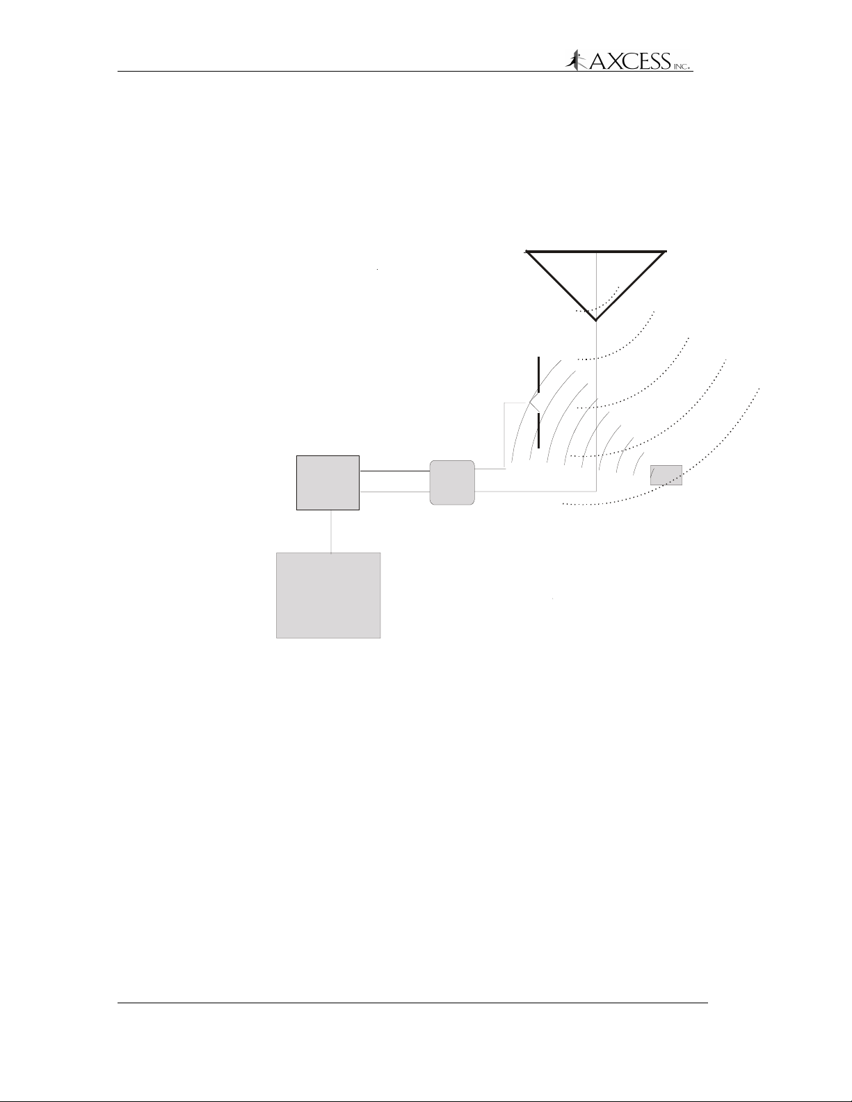
The following diagram (Figure 3) shows a very basic AXCESS NT132
system. The system has the following components:
• A Reader to send radio signals to a transmitting antenna,
receives radio signals from a receiving antenna and outputs the
data to some device – a computer or a Wiegand control panel,
for instance.
• A transmitting antenna to “wake up” any Tags in the area.
• An Antenna Tuning Unit (ATU) placed between the Reader and
the Antennas to properly tune the transmitting antenna to its
surrounding environment.
• Tags to receive wake-up radio signals and broadcast their IDs to
the receiving antenna. Tags can be carried by individuals, placed
on equipment or in vehicles.
• A receiving antenna to intercept radio signals from the Tags and
to pass the signals to the Reader.
• One or more of the following: a computer for data storage, a
peripheral device such as a light, buzzer, door strike, gate
Page 14
NT132 System Overview
controller, camera, etc., and/or a control panel that accesses a
computer or a device.
An NT132 system may be as simple as a single Reader and Bar
Antenna controlling the front door of a small office or it may comprise
a network of interconnected devices and Readers controlled by a
computer.
Transmitting Antenna
U
Low Frequenc y Wakeup Signal
Receiving
Antenna
H
F
T
a
g
R
e
s
p
o
n
s
e
Reader
Device
(Computer, controller
door strike, camera
etc.)
Figure 3 A simple AXCESS NT132 System
RX
TX
ATU
Tag
14 750.001.003
Revised June 1999
© 1999 AXCESSTM Inc.
Page 15

Tags
NT132 System Overview
A Tag is a very small transponder (transmitter + responder) that
remains in a sleep state (off) until awakened. When the Tag receives
a special wake-up signal from the Reader, the Tag will wake up (turn
on) and emit a radio signal of its own. The signal emitted by the Tag
is typically its pre-programmed identification number – but could
include other data as well. The signal is generally used for detection,
identification and location of people or objects.
An AXCESS Tag, encased in black or beige plastic, is about the size
of a credit card and is approximately 200 mils thick. Some Tags have
slots to attach personnel ID pictures to them. Other Tags may be
attached permanently to vehicles or assets such as computers.
Types of Tags
The typical types of Tags are:
Passive Tags
A passive tag does not have an on-board power source (battery). It is
powered from the antenna radiation field of the transmitter that is
trying to wake the tag up. It uses the same antenna for transmitting
and receiving.
Active Tags
An active tag has its own battery and is capable of a greater transmit
distance (range) than the passive tag. An active tag only has a
transmitting antenna. It is common for active tags to continually
transmit and the system will only report those tags in the reception
field.
AXCESS Tags
AXCESS Tags, based on AXCESS NeuroTag technology, are a
hybrid of active/passive and do not respond until awakened. The tag
is in a “sleep” state that requires almost no power until the tag is
activated. AXCESS Tags receive on a low frequency and transmit on
an ultra high frequency.
The Tag checks the wakeup signal for proper modulation and a
Reader ID code, then transmits its own ID number along with the
Reader ID that woke it up.
© 1999, AXCESSTM Inc. 750.001.003
Revised June 1999
15
Page 16

NT132 System Overview
Reader
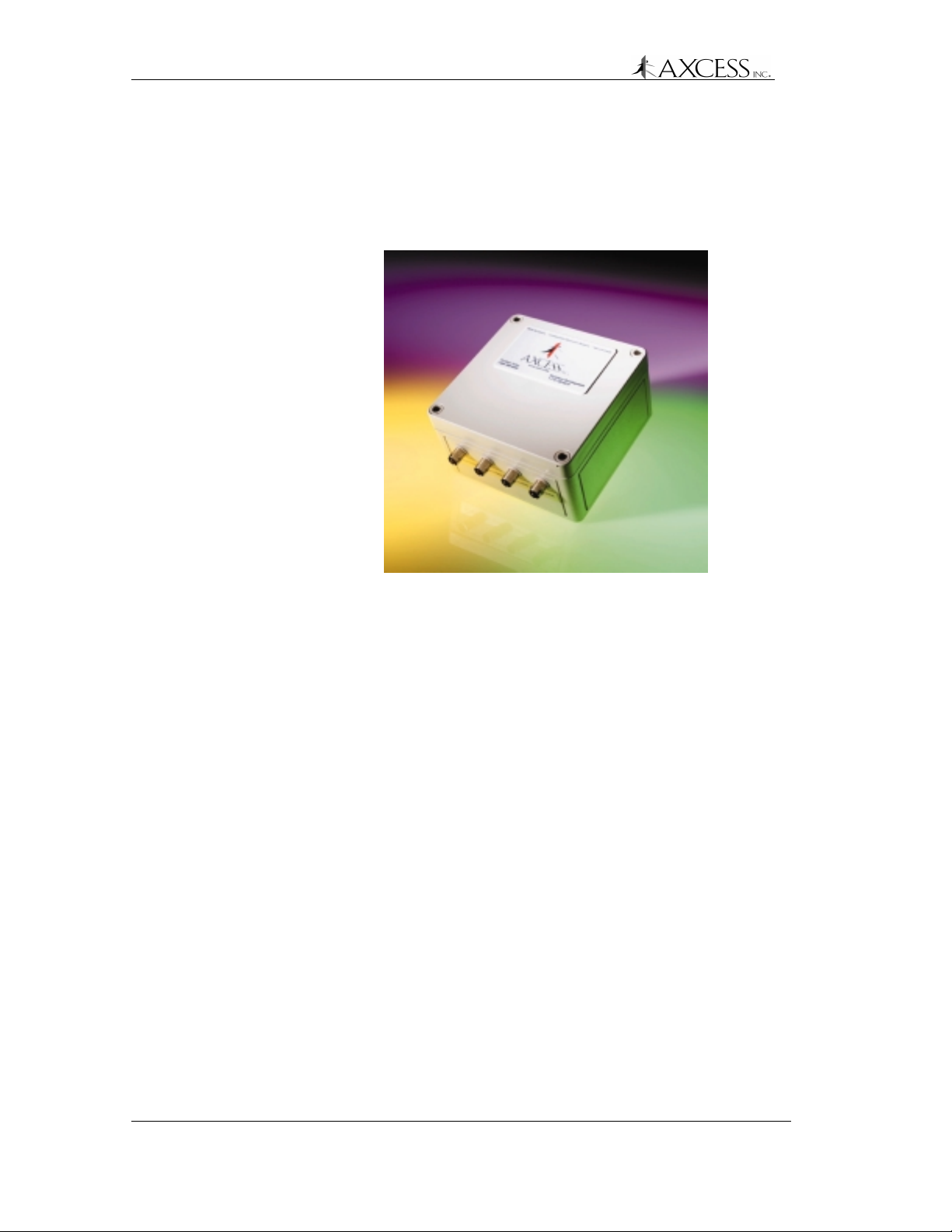
The Reader (Figure 4) originates the signal that is broadcast to wake
the Tag. The Reader has the following purposes:
• Encode a transmission wake-up signal and transmit it via the
antenna to the sleeping Tag.
• Decode the signal from the Tag via the receiving antenna. The
Reader will convert the data to a format usable by a computer or
Wiegand control panel for further processing of the information.
• Output data to a control device or a computer.
Figure 4 AXCESS Reader – external view
Types of Readers
Serial
This Reader communicates using the EIA-232 standard, more
commonly known as RS-232C. It can connect to a communications
port on a computer or any device that can accept RS-232C data.
Wiegand
Wiegand Readers output Security Industry Association (SIA) 26-bit
data to Wiegand control panels. It connects to the Wiegand control
panel by three wires – Data One, Data Zero and Ground.
Free Topology Transceiver (FTT)
FTT Readers can be used to create networks of Readers. They
communicate with a computer using Echelon LonWorks
control external devices via TTL controls.
TM
and can
16 750.001.003
Revised June 1999
© 1999 AXCESSTM Inc.
Page 17

Antennas
NT132 System Overview
Because the Tags receive and transmit at different frequencies,
different antennas are used for each leg of the communication.
Antenna construction is related to the wavelength (or fraction thereof)
of its design frequency. Antennas designed for the Ultra High
Frequency spectrum (to receive the transmit signal from the Tag) can
be quite short. Antennas designed for Very Low Frequencies (to
transmit the wake-up signal to the Tags) must be quite long. The
transmitting antenna is a loop and the receiving antenna is a dipole.
Types of Ant ennas
For interior use, antennas can be inconspicuously mounted – for
example, hidden in a false ceiling or disguised as a common picture
frame. Also, depending on type of installation, the transmitting
antenna and receiving antenna may be combined into a single
enclosure or may be built as separate units.
Road Loop and Dipole Antennas
The Road Loop and Dipole Antennas are used for identifying Tags in
vehicles. The Road Loop Antenna is installed in the road surface and
sends out wake-up signals. The Dipole Antenna is separate from the
Road Loop Antenna and is mounted so that it can receive
transmissions from the Tags.
Bar Antenna
The Bar Antenna has both transmitting and receiving antennas
enclosed in a box that is approximately 2 feet long, 5 inches wide and
1 inch thick. It can be inconspicuously mounted above or next to a
door or above the ceiling tiles.
Swing Frame Antenna
The Swing Frame Antenna has both transmitting and receiving
antennas built into its frame. The antenna enclosure is designed as a
picture frame so that it may be mounted unobtrusively on walls.
© 1999, AXCESSTM Inc. 750.001.003
Revised June 1999
17
Page 18
NT132 System Overview
Antenna Tuning Unit (ATU)
An Antenna Tuning Unit or ATU (Figure 5) maximizes the signal
transmission from the Reader. It is installed between the Reader and
the transmitting and receiving antennas.
Figure 5 AXCESS ATU – external view
On the bottom of the ATU, there are two jacks to connect to the
transmitting and receiving antennas and two jacks to connect to the
Reader.
Types of ATUs
There are two kinds of ATUs currently provided. Although they
require different methods of optimizing performance, they perform
the same function.
Toggle Switch ATU
This ATU has a toggle switch, a rotary switch and a voltmeter. The
antenna performance is tuned by toggling one switch between three
positions and turning the other switch among ten positions. The
voltmeter indicates when the optimal setting has been reached.
Jumper ATU
This ATU has eleven 3-pin headers and five LEDs. The antenna
performance is tuned by moving jumpers on the headers. Optimal
performance is indicated by the strength of the LEDs.
18 750.001.003
Revised June 1999
© 1999 AXCESSTM Inc.
Page 19
Reader Installation
Introduction
The Reader is the brain of the NT132 system. Its functions include
sending wakeup signals, receiving Tag signals, processing Tag data,
and routing Tag data.
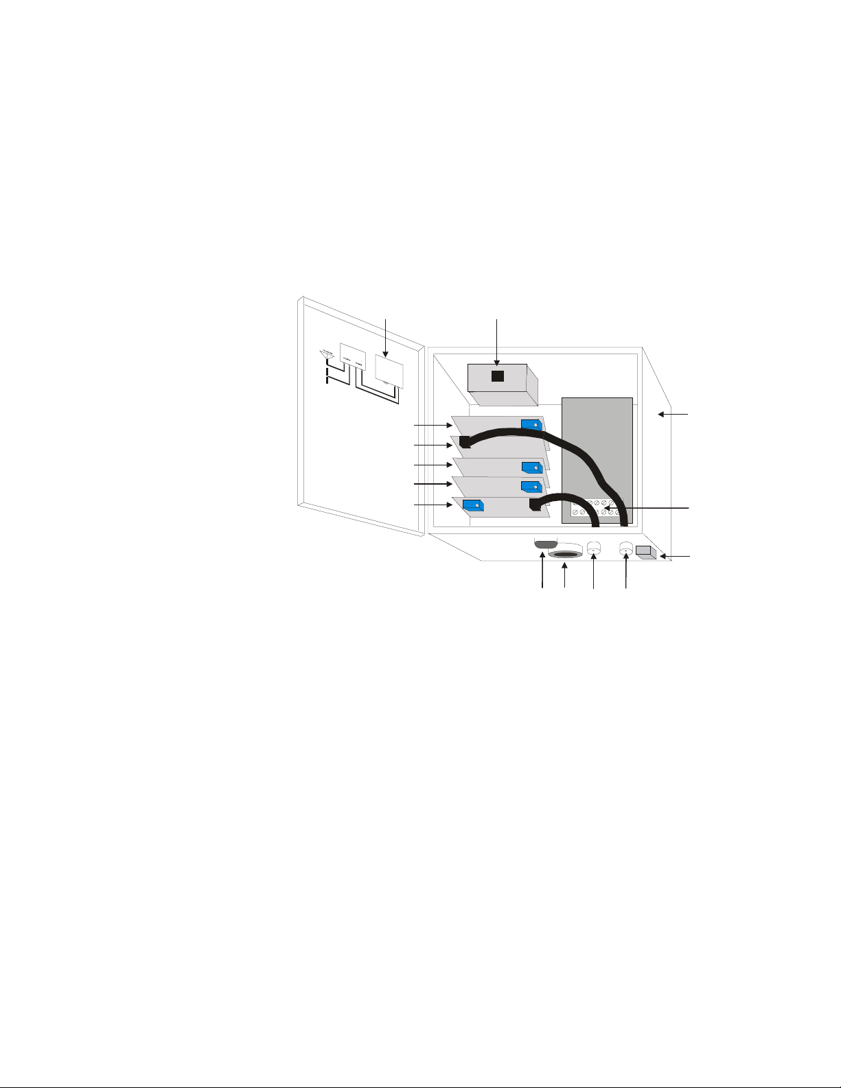
Cabling Label
Unilon RX Card
RF Card
Unilon Output Card
Unilon TX Card
Transmitter Card
RJ-45
Conduit
Chase
TX
RXRS-232
Figure 6 Reader – internal view
The Reader (Figure 6) in a typical AXCESS system consists of the
following:
Reader Case
Terminal Block (TB1)
Ground Lug
• A stack of sub-controller Printed Circuit Board (PCB) cards:
Unilon RX Card – decodes the signal sent from the receiving
antenna through the RF card
RF Card – receives the signal from the receiving antenna
Unilon Output Card – sends the data to a controller or
computer
Unilon TX Card – encodes the transmission signal
Transmitter Card – sends the signal to the transmitting
antenna
• Two external female BNC connectors to connect to the Antenna
Tuning Unit (ATU)
Page 20

Reader Installation
• External DB9 RS-232 female connector to connect to a computer
or device
• Conduit chase for wiring access through the Reader case
• White terminal block with connections for Wiegand ground, Data
One and Data Zero, and connections for 24V power and ground
• RJ45 connector used by AXCESS for programming the Reader’s
firmware
Reader Types
Serial Reader
This type of Reader can interface directly with the communications
port of a computer or another control device that process standard
EIA-232 serial data.
Wiegand Reader
This is type of Reader outputs standard SIA 26-bit Wiegand data and
is used when interfacing with a standard Wiegand controller.
Required Materials
For each Tag read, the Reader outputs data every 750 milliseconds.
Duplicate Tag information is stored in the Reader’s buffer for 12
seconds so that redundant Tag reads are ignored during the this time
interval.
FTT Readers
FTT (Free Topology Transceiver) Readers are for installations
involving a network of Readers connected to one another. This is
accomplished via twisted-pair wiring over a total distance of up to
8,800 feet. FTT Readers can also control devices according to data
sent over the network by the host computer.
The following materials are necessary for a successful installation:
• Power drill and bits
• Screwdrivers – Phillips and flathead
• 4 # 10 Anchors, Plastic (for mounting in drywall or mortar)
• 4 # 10 Self threading screws
• 4 # 10 Washers
• Depending on the surface that the Reader will be mounted on,
you may need #10 molly bolts.
20 750.001.003
Revised June 1999
© 1999 AXCESSTM Inc.
Page 21
• Each Reader type has it own required materials for connecting to
third-party devices. Please see the specific section for the
Reader that you are installing.
Mounting the Reader - All Types
All Readers have the same mounting requirements.
IMPORTANT! Before permanently mounting any piece of the
AXCESS NT132 System, first lay out and test the entire system.
Step 1: Select a Reader location consistent with the type of
antenna being installed. The Reader should be a minimum
of 36 inches off the ground, preferably at eye-height.
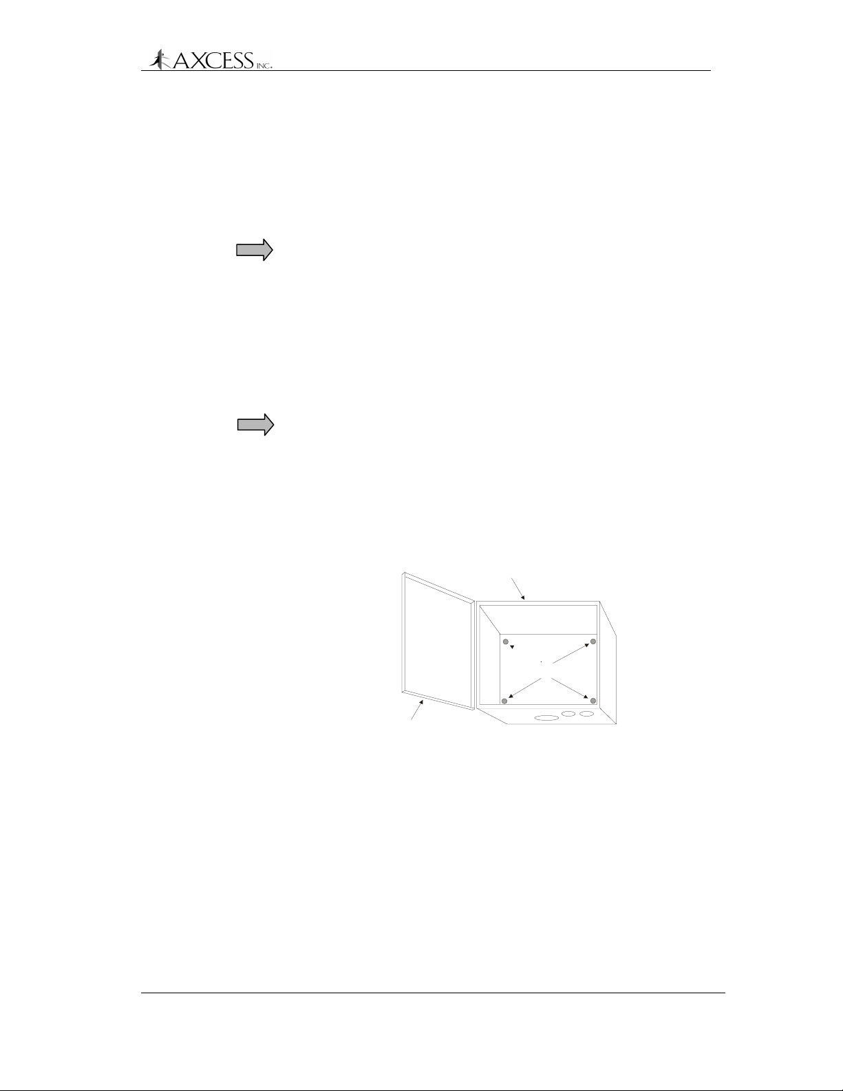
Step 2: Mount the Reader securely with the cover hinge on the left
and external connectors on the bottom (Figure 6). Screw
holes are provided inside the cabinet for mounting to a wall
(Figure 7).
IMPORTANT! When you mount the Reader, be careful not
to damage the electronic components. A manual
screwdriver is recommended for tightening the screws.
Reader Installation
Other installation techniques may better satisfy specific
site conditions - L-brackets or double-sided tape to mount
the Reader, or placement of the Reader inside an
enclosure on a shelf.
Reader Cabinet
Mounting Holes
Hinged Cover
Figure 7 Reader mounting holes
Step 3: Go to the following sections for the type of Reader that you
are installing:
Serial Reader – Installation of a Serial Reader, page 22.
Wiegand Reader – Installation of a Wiegand Reader, page
23.
FTT Reader – Installation of an FTT Reader System, page
25.
© 1999, AXCESSTM Inc. 750.001.003
Revised June 1999
21
Page 22

Reader Installation
Installation of a Serial Reader
Required Materials
• A standard one-to-one connection RS-232 cable (computer
modem cable) of sufficient length to connect the Reader to any
device that accepts RS-232 as input. The length required for your
installation will vary. One end needs to be a DB9 male connector.
IMPORTANT! DO NOT use a null-modem cable or a null-modem
adapter.
Connecting the Serial Reader to a Computer or Device
Step 1: Attach the female end (it can be either DB25 or DB9
according to the device serial connector) of the cable to
the third-party device. Connect the DB9 male end to DB9
female connector on the Reader.
Step 2: For the third-party device, configure the communications
port settings to the following:
Baud Rate 4800
Data Bits 8
Parity None
Stop Bits 1
Flow Control None
The Reader is a DCE (Data Circuit-terminating Equipment)
device, and data is output through a DB9 female RS-232
connector. Only the following pin assignments are used:
• Transmitted Data (pin 2)
• Received Data (pin 3)
• Signal Ground (pin 5)
Note: Although the Serial Reader has a terminal block
labeled with Wiegand Data Zero, Data One and Ground, it
cannot be used to connect to a Wiegand control panel.
Step 3: Apply power to the Reader. See section Connecting Power
to the Reader – All Types, page 32.
22 750.001.003
Revised June 1999
© 1999 AXCESSTM Inc.
Page 23
Installation of a Wiegand Reader
Required Materials
• Black, white and green wire of sufficient length to connect the
Reader to the Wiegand control panel. With 22-gauge wire, 200
feet of wire can be run. With 18 gauge, 500 feet can be run.
• A very small flathead screwdriver
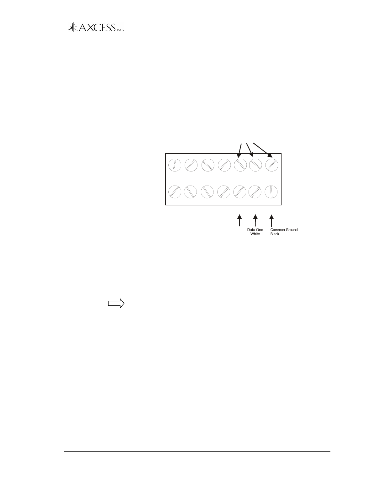
Reader Installation
Ribbon-cabled to UniLon Output
Card in PCB stack
GD0
24V
Data Zero
Green
Wires from Wiegand
Control Panel
D1
G
Figure 8 Wiegand Reader connections
Connecting the Wiegand Reader to a Wiegand Control
Panel
Note: Although the Wiegand Reader has a serial output, it cannot be
converted to a Serial Reader. The serial output can only be used for
Reader configuration and diagnostics.
Step 1: Install the Wiegand control panel according to the
instructions provided with that unit.
Step 2: Open the Reader case and disconnect the BNC connector
running from the Transmitter card at the TX connector
(Figure 6). This will give you access to the terminal block
underneath.
Step 3: Loosen the white terminal block by unscrewing it. This will
give you access to the terminals.
Step 4: The ground connection protects against any differential in
voltage potential at each ground plane that may cause
current to flow between the external panel and the Reader.
Such a condition could damage and/or impact the
performance of either or both units.
© 1999, AXCESSTM Inc. 750.001.003
Revised June 1999
23
Page 24

Reader Installation
Run the ground wire from the Ground connection at the
Wiegand control panel to the G terminal on the Terminal
Block (TB1, see Figure 8) in the Reader. For standard
Wiegand control panels, the Ground wire is black. Ensure
that the termination is secure, but not over-tight. Route
cables through the conduit chase at the bottom of the
Reader.
Step 5: Run the Data One wire from the Wiegand control panel to
D1 on the Terminal Block. For standard Wiegand control
panels, the Data One wire is white.
Step 6: Run the Data Zero wire from the Wiegand control panel to
D0 on the Terminal Block. For standard Wiegand control
panels, the Data Zero wire is green.
Note: If Data One and Data Zero are connected
backwards, the data will be garbled.
Step 7: Screw the white terminal block down.
Step 8: Reconnect the TX cable connector.
Step 9: Ensure the Wiegand control panel is wired correctly.
Step 10: Enter the Tag numbers into the panel’s database
according to the panel manufacturer’s instructions.
Step 11: Apply power to the Reader. See section Connecting Power
to the Reader – All Types, page 32.
24 750.001.003
Revised June 1999
© 1999 AXCESSTM Inc.
Page 25
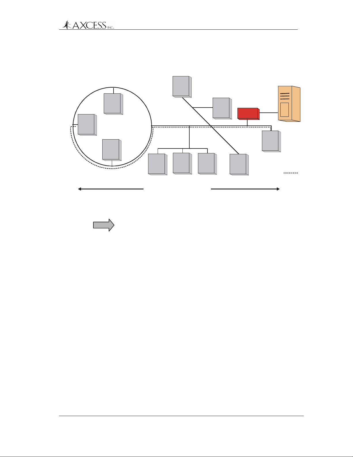
Installation of an FTT Reader System
Introduction
The AXCESS Free Topology Transceiver (FTT) Reader System is
for network applications involving multiple, interconnected Readers
(Figure 9).
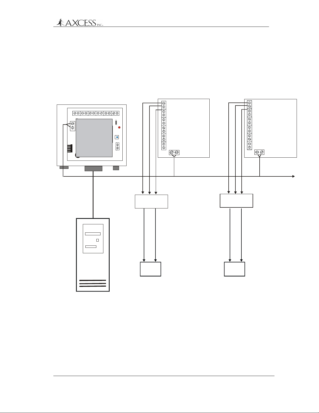
Reader Installation
Serial Gateway
FTT
Jp1
Jp4
Reader 1
24V
Ground
Door Stri k e
FTT Motherboard
Jp3
Jp5
Jp6
FTT
Reader 2
24V
Ground
Door Strike
FTT Motherboard
FTT
Tw is ted Pair
LonWorks Network
+ Trigger
Sensit iv e Trig ge r
Serial Data
Relay
Sensitive Trigger
Relay
To more Readers
+ Trigger
Common Ground
NC (normally closed)
or NO (normally open)
Computer
Device
Figure 9 FTT Reader system
The FTT Reader System has at least one of each of the following:
• An FTT Reader that can connect to several external devices and
to other FTT Readers.
• A computer to drive the system. The computer collects data from
the tags. The computer may also send commands via the
Readers to other devices that control doors, send alarms, turn on
lights, etc.
© 1999, AXCESSTM Inc. 750.001.003
Revised June 1999
Common Ground
Device
NC (normally c losed)
or NO (normally open)
25
Page 26

Reader Installation
• A Serial Gateway that coverts the computer’s RS-232 data to
LonWorks data and vice versa. LonWorks is the protocol used to
communicate with the FTT Readers. The Serial Gateway
transmits data from the computer to the Readers via twisted pair
wire. Up to thirty-one FTT Readers can be connected to the
Serial Gateway.
Note: Although the Serial Gateway has a terminal block, it cannot
directly control any access devices. Do not wire access devices to
the Serial Gateway.
Required Materials
• Unshielded twisted pair wire to run between Readers. The type of
cable chosen affects the cable distances allowed in the FTT
network. The recommended cable lengths are given in the next
section.
• Belden 85102, 16 AWG, single twisted pair, stranded 9/29,
unshielded, plenum
• Belden 8471, 16 AWG, single twisted pair, stranded 9/29,
unshielded, non-plenum
• Level IV, 22 AWG, twisted pair, typically solid and unshielded
• TIA 568A Category 5, 24 AWG, twisted pair, unshielded. This
cable type is recommended because it allows for upgrades.
• Sensitive trigger, TTL relays to drive door strikes or other devices
(for example, Altronix RBSN-TTL or Alarm Saf RBKS-124P)
• 22 AWG wire, max four feet in length, to connect the FTT
Readers to the relays.
• Wire as specified by device manufacturers to connect the
devices to the relays.
• An RS-232C straight-through cable with a DB9 male connector to
connect the Serial Gateway to a computer.
26 750.001.003
Revised June 1999
© 1999 AXCESSTM Inc.
Page 27
Reader Installation
Network Specifications
An FTT network can be comprised of a loop, star, bus or a mixture of
wiring topologies (Figure 10).
PC
Serial
Gateway
Max node to node
distance:
Up to 32 FTT R e aders
Figure 10 Example FTT network – a mixture of bus, star and ring
wiring topologies
IMPORTANT! Both of the following specifications must be met for
proper system operation:
Cable Type Max node to node
distance
Max total wire
length
Belden 85102 1640 feet (500 m) 1640 feet (500 m)
Belden 8471 1312 feet (400 m) 1640 feet (500 m)
Level IV 1312 feet (400 m) 1640 feet (500 m)
Category 5 820 feet (250 m) 1475 feet (450 m)
Max Node to Node Distance
The distance from each Reader to all other Readers on the network
must not exceed the maximum node-to-node distance. If multiple
paths exist, e.g., a loop topology, then the longest path should be
used for calculations (Figure 10).
Max Total Wire Length
Maximum total wire length is the total amount of wire connected per
network.
© 1999, AXCESSTM Inc. 750.001.003
Revised June 1999
27
Page 28

Reader Installation
Connecting the Serial Gateway to the PC
Step 1: Connect the male DB9 end of the straight-through serial
cable to the female DB9 connector at the bottom of the
Reader.
Step 2: Connect the other end of the serial cable to the PC.
Step 3: The Serial Gateway has pads so that it can be placed on
top of or next to the PC.
Step 4: Configure the communications port settings on the PC as
follows:
Baud 2400
Data Bits 8
Parity None
Stop Bits 1
Flow Control None
The Serial Gateway is a DCE (Data Circuit-terminating
Equipment) device, and data is output through a DB9
female RS-232 connector. Only the following pin
assignments are used:
• Transmitted Data (pin 2)
• Received Data (pin 3)
• Signal Ground (pin 5)
Connecting the Serial Gateway to an FTT Reader
Step 1: Prepare a sufficient length of twisted pair wire to connect
the first Reader to the Serial Gateway.
Step 2: Insert the twisted pair wire into the terminal block labeled
FTT in Figure 11 in the Serial Gateway and run it out the
conduit chase.
Step 3: Run the twisted pair through the conduit chase of the
Reader and insert the twisted pair wire into the FTT
terminal block. You can connect up to four Readers by the
FTT terminal block in the Serial Gateway; however, we
recommend connecting only one or two. You can network
up to thirty-one Readers together by twisted pair wire.
Connecting FTT Readers to Each Other
Step 1: Prepare a sufficient length of twisted pair wire to connect
the two Readers.
28 750.001.003
Revised June 1999
© 1999 AXCESSTM Inc.
Page 29
Reader Installation
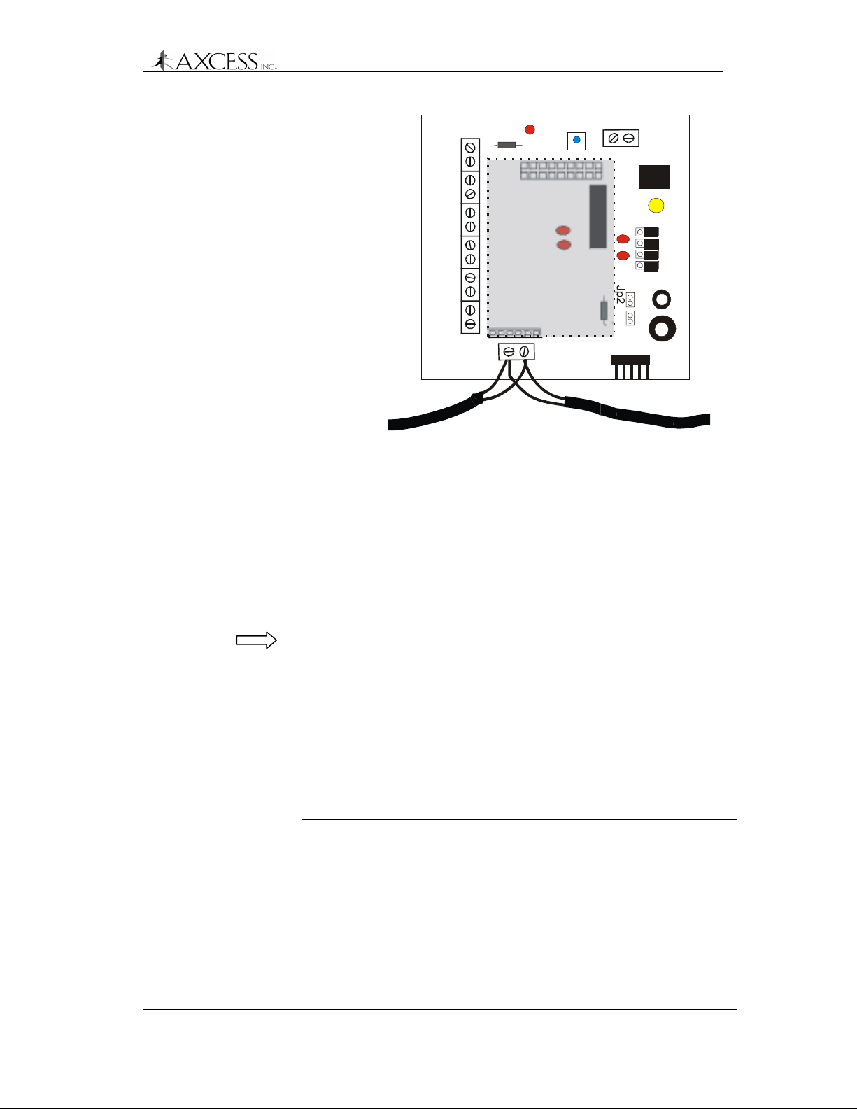
Power
Grnd 24V
Power for relay
24V
Grnd
FTT terminal block
1
Jp3
Jp5
Jp6
Jp4
Jp1
FTT
Figure 11 FTT Motherboard. Gray area notes location of the
LonWorks daughterboard.
Step 2: Insert the twisted-pair wire into the terminal block labeled
FTT (Figure 11) in the first Reader and run it out the
conduit chase.
Step 3: Run the twisted pair through the conduit chase of the
second Reader and insert the twisted pair wire into the
FTT terminal block. Each terminal in the FTT terminal
block can hold up to four wires, depending on gauge.
Note: When connecting Readers to each other, remember that
shorter cabling makes for a better network because it improves
transmission.
Connecting an FTT Reader to a Device
The FTT Reader has two outputs to control devices. These outputs
can be found on the FTT Terminal block (Figure 11).
The terminals in the FTT terminal block are for the following:
Label Purpose
24V 24V for powering the TTL relay
Gnd Ground for the TTL relay
Door Strike Trigger output with a 20 mA source/sink
capability for triggering sensitive trigger relays.
Secondary
Output
Trigger output with a 20 mA source/sink
capability for triggering sensitive trigger relays.
© 1999, AXCESSTM Inc. 750.001.003
Revised June 1999
29
Page 30

Reader Installation
24V
Ground
Door Strike
Secondary
Output
FTT ter mi nal block
IMPORTANT! Do not use the Door Strike and Secondary Output
terminals to drive relay modules directly. Such relays require 100 mA
or more, well in excess of the FTT module’s source power capacity.
The FTT card can burn up. Using sensitive trigger, TTL relays (for
example, Altronix RBSN-TTL or Alarm Saf RBKS-124P) is
recommended.
NOTE: The rolled-up serial cable connected to the RS-232 connector
is for configuration and diagnostics. The FTT Reader cannot be
converted to a Serial Reader.
Trig -
Pos +
C
NC
NO
TTL Relay
Trig +
Neg -
C
NC
NO
Device can be wired to either:
Device can be wired to either:
NC - Normally Closed
NC - Normally Closed
NO - Normally Open
NO - Normally Open
Device
Power Supply
for Device
+V
G
Figure 12 Wiring details for driving a device
Step 1: Run 22 AWG wire (max length two feet) from the terminal
labeled GND on the FTT terminal block through the
conduit chase to the relay terminal labeled Neg -.
Step 2: Run 22 AWG wire (max length four feet) from the terminal
labeled either Door Strike or Secondary Output on the
FTT terminal block through the conduit chase to the relay
terminal labeled Trig +.
Step 3: Run 22 AWG wire (max length four feet) from terminal
labeled 24 V on the FTT terminal block through the conduit
chase to the relay terminal labeled Pos +.
Step 4: Connect the Common (C) terminal on the relay to +V on
the device’s power supply with manufacturer
recommended wire.
Step 5: Connect Ground from the device’s power supply to the
device using manufacturer recommended wire.
30 750.001.003
Revised June 1999
© 1999 AXCESSTM Inc.
Page 31

Reader Installation
Step 6: Connect either the Normally Open (NO) or Normally
Closed (NC) terminal on the relay to the device with
manufacturer recommended wire.
Applying Power to the Serial Gateway
Step 1: Ensure that the 110V AC outlet is close by and easily
accessible.
Step 2: Plug the AC adapter into the connector at the bottom of
the Serial Gateway.
Step 3: Plug the adapter into 110 AC wall outlet or UPS.
© 1999, AXCESSTM Inc. 750.001.003
Revised June 1999
31
Page 32

Reader Installation
Connecting Power to the Reader – All Types
IMPORTANT! Finish installing the Reader before applying power.
All Readers come with a 24V, 700 mA wall adapter that plugs into a
110 outlet. If uninterruptible power is an issue, a UPS can be used.
Wires to
Reader
24V
Wires from
AC adapter
GD0
D1
G
Figure 13 Power terminals for the Reader
Grounding the Reader
The Reader needs to be properly grounded. Failure to ground the
Reader will result in erratic performance.
Step 1: Run 14 AWG wire from a solid earth ground to the ground
lug on the outside of the Reader case (Figure 6).
Step 2: If the Reader is connected to a Wiegand control panel,
ensure that the Wiegand control panel is similarly
grounded.
AC Adap ter
The AC adapter wires (Figure 14) are labeled as follows:
Power
80 C VW - 1 22 AWG X 2C
Ground
Figure 14 AC adapter wires
Power is marked with the dashed white line.
Ground is black and has the gauge information printed on it.
32 750.001.003
Revised June 1999
© 1999 AXCESSTM Inc.
Page 33

Reader Installation
Step 1: Ensure that the 110 AC outlet is near the Reader and is
easily accessible.
Step 2: Open the Reader case and disconnect the BNC connector
running from the Transmitter card at the TX connector
(Figure 6). This will give you access to the terminal block
underneath.
Step 3: Loosen the white terminal block by unscrewing it. This will
give you access to the terminals.
Step 4: Run the power wires through the conduit chase.
Step 5: Insert the positive 24V wire into the terminal labeled 24V
(Figure 13).
Step 6: Insert the ground wire into the terminal labeled G.
Step 7: Screw the white terminal block down.
Step 8: Reconnect the TX cable connector.
Step 9: Plug the AC adapter into a 110 outlet.
When power is supplied to the Reader, the LEDs on the card stack
will light up.
Note: The open terminals on TB1 are for future enhancements.
IMPORTANT! The Reader comes with a factory-default ID number
that needs to be changed to eliminate the possibility of cross talk.
See the section Configuring 3.x Reader Firmware, page 35.
© 1999, AXCESSTM Inc. 750.001.003
Revised June 1999
33
Page 34

Page 35

Configuring 3.x Reader Firmware
A 3.x Reader can be configured by a terminal application to do the
following:
• Set modes for reading either 2.0 Tags or 3.x Tags.
• Change the Reader ID number to eliminate the possibility of
cross talk in multi-Reader applications.
• Place the Reader in diagnostics mode so that Reader and Tag
performance can be monitored.
HyperTerminal is a convenient terminal application for
communicating with a Reader since it is standard with the
Windows
programs, such as ProCom, etc., can be used.
Required Materials
• A computer with a terminal program and a free communications
• A standard one-to-one computer modem RS-232 cable with a
TM
operating system. Although other terminal emulation
port. A laptop running Windows is recommended for
convenience.
DB9 male connector.
IMPORTANT! DO NOT use a null-modem cable or null-modem
adapter.
Connecting a Computer to the Reader
Serial and Wiegand Readers
Step 1: Attach the DB9 male connector of the RS-232 cable to the
RS-232 port on the Reader
Step 2: Attach the other end of the RS-232 cable to the computer.
FTT Reader
Step 1: Open the Reader case. There is a 9-wire ribbon cable
connected to the RS-232 port. The other end is
unconnected and tied. There is a 10-wire ribbon cable
connecting the output card to the FTT motherboard
(Figure 15).
Step 2: Disconnect the 10-wire ribbon cable from the output card.
Step 3: Connect the free end of the 9-wire ribbon cable to the
output card (Figure 15). The red wire should be closest to
the Reader case’s hinges.
Page 36

Configuring 3.x Reader Firmware
RS-232 cable
attached to the
output card.
The red wire is
closest to the
Reader case.
Figure 15 FTT Reader with the output card disconnected from
the FTT motherboard and connected to the RS-232 port.
RS-232
Step 4: Attach the DB9 male connector of the RS-232 cable to the
external RS-232 port on the Reader.
Step 5: Attach the other end of the RS-232 cable to the computer.
Remember: When you have finished communicating with
the Reader, detach the 9-wire ribbon cable from the output
card, reattach the 10-wire ribbon cable from the FTT
motherboard to the output card and detach the computer
from the Reader.
36 750.001.003
Revised June 1999
© 1999 AXCESSTM Inc.
Page 37

Configuring 3.x Reader Firmware
Communicating with the Reader via HyperTerminal
Step 1: On the computer’s desktop, click the Start button. The
Start menu will appear (Figure 16).
Step 2: From the Start menu, select Programs, Accessories,
Communications, HyperTerminal.
Figure 16 Accessing HyperTerminal from the Start Menu
Step 3: In the Explorer window that appears, double-click the
Hypertrm.exe icon. This launches the HyperTerminal
application.
Step 4: In the Connection Description dialog box that appears,
enter any name for the connection in the Name field, and
select the first icon in the Icon selection box. Click the OK
button.
Step 5: In the Connect To dialog box that appears, select the com
port to which the Reader is connected from the Connect
Using drop-down list. The other options will gray out. Click
the OK button.
Step 6: In the Com Properties dialog box that appears, enter the
following information depending on the Reader type to
which you are connecting:
Serial Reader and Wiegand Reader:
Bits per second (Baud) 4800
Data Bits 8
Parity None
Stop Bits 1
Flow Control None
FTT Reader:
Bits per second (Baud) 2400
© 1999, AXCESSTM Inc. 750.001.003
Revised June 1999
37
Page 38

Configuring 3.x Reader Firmware
Step 7: Click the OK button. If you are connecting to a Serial
Reader Commands
The following is a list of commands that can be sent to the Reader
via the terminal application.
Code Action
* Changes the Tag version that the Reader reads.
Data Bits 8
Parity None
Stop Bits 1
Flow Control None
Reader, the HyperTerminal’s main window will display the
five-digit ID numbers for any Tags in the field. Wiegand
and FTT Readers will not output anything to the screen
unless they are placed in diagnostics mode (See the
section Toggling Between Default and Diagnostic Modes,
page 42.)
This should be checked to ensure that the Reader is
reading the correct version of Tag. A Reader can only read
2.0 Tags or 3.x Tags; it cannot read both.
# Changes the Reader ID to eliminate the potential of cross
talk.
& Turns on/off diagnostic mode.
$ Allows the Reader to act on a 254 code in addition to its
own ID number. This is only available for Wiegand
Readers.
38 750.001.003
Revised June 1999
© 1999 AXCESSTM Inc.
Page 39

Entering a Command
Step 1: In HyperTerminal’s main window, press the Spacebar until
Step 2: Type one of the above commands at the “Enter:” prompt.
Configuring 3.x Reader Firmware
the Reader responds with “Enter:” on the terminal screen.
The Reader will now wait for input.
Note: When the Reader is waiting for input, it is paying
attention only to the serial cable and is not receiving
information from the antennas.
For example,
Enter: &
Places the Reader into diagnostics mode.
IMPORTANT! Do not press the Enter key after you have
typed the command; it is not necessary.
If the Reader receives no input after a few seconds, it
displays the message, “Timed out.” If you are
communicating with an FTT Reader, the Reader displays
the firmware version, jumper settings and Reader ID.
All outputs from the Reader are preceded by an indent to
indicate that the string is not a Tag ID.
© 1999, AXCESSTM Inc. 750.001.003
Revised June 1999
39
Page 40

Configuring 3.x Reader Firmware
Toggling between reading 3.x Tags and reading 2.0 Tags
Readers can receive information from either 2.0 Tags or 3.x Tags,
but not both. The toggle command lets you to switch between them.
IMPORTANT! Ensure that the Tag version the Reader is receiving
matches the version stamped on the edge of the Tag case. If the
Reader and Tags are mismatched, no Tag information will be output.
The Tag version information is stored so that the Reader will continue
to read the same Tag version even if it has been powered off and
powered back up.
Step 1: Type an asterisk (
Do not press Enter.
The Reader will respond with, “Reading 2.0 tags.”
For example:
Enter: *
Reading 2.0 tags.
Step 2: To switch back to reading 3.x Tags, press the Spacebar
until the “Enter:” prompt appears, then type an asterisk at
the “Enter:” prompt.
The Reader will respond with “Reading 3.x tags.”
* ) at the “Enter:” prompt.
40 750.001.003
Revised June 1999
© 1999 AXCESSTM Inc.
Page 41

Changing the Reader ID Number
IMPORTANT! All Readers are given the same ID number (127) at
the factory. Each Reader needs to be set with a unique ID number to
eliminate the possibility of cross talk (i.e., a Tag broadcasting to an
incorrect Reader) in multi-Reader applications.
Step 1: At the “Enter:” prompt, type a pound sign ( # ) followed by
a two-number code (01-32). See Table 1 for codes and
their corresponding Reader ID numbers.
Do not press Enter.
The Reader will respond with “Selected Value: #NN”
where NN is the code that you entered, and “Reader
ID=XXXXX” where XXXXX is the new Reader ID number
corresponding to the code entered.
For example, if you type:
The Reader will respond with
Configuring 3.x Reader Firmware
Enter: #10
Selected Value: #10
Reader ID=00106
The new Reader ID number will be kept even after a
power off/on cycle.
Code to
Enter
00 00000 16 00080
01 00033 17 00113
02 00034 18 00114
03 00003 19 00083
04 00100 20 00052
05 00069 21 00021
06 00070 22 00022
07 00103 23 00055
08 00072 24 00024
09 00105 25 00057
10 00106 26 00058
11 00075 27 00027
12 00044 28 00124
13 00013 29 00093
14 00014 30 00094
15 00047 31 00127
Table 1 Reader ID codes and numbers
Reader
ID #
Code to
Enter
Reader
ID #
© 1999, AXCESSTM Inc. 750.001.003
Revised June 1999
41
Page 42

Configuring 3.x Reader Firmware
Toggling Between Default and Diagnostic Modes
Diagnostic mode allows you to troubleshoot the NT132 system. It
displays information that the Tag broadcasts to the Reader – the
Reader ID, Site Code and Tag ID number.
Step 1: At the “Enter:” prompt, enter an ampersand ( & ).
Do not press Enter.
The Reader will respond with “Diagnostics ON”
A Reader reporting 3.x Tag information will output 15 digits
to the terminal screen:
R R R R R S S S S S T T T T T
Where:
R – The 5-digit Reader ID as returned by the Tag
S – The 5-digit Site Code of the Tag
T – The 5-digit Tag ID number
A Reader reporting 2.0 Tag information will output 10 digits
to the terminal screen:
S S S S S T T T T T
Where:
S – The 5-digit Site Code of the Tag
T – The 5-digit Tag ID number
For example, turning on the diagnostics mode for Reader
reporting 3.x Tags looks like this:
Enter: &
The Reader will respond with
Diagnostics ON
001060002401234
001060002423235
001060002467843
00106 is the Reader ID; 00024 is the Site Code and
01234, 23235 and 67843 are the IDs of the Tags that are
in the field.
Code 254
When the Tag determines that a Reader signal is present but cannot
determine the Reader ID number, the Tag returns 254 for Reader ID
as a code indicating that it could not pick up the Reader ID number.
When the Reader is in default mode, it will not report the 254 code as
it would with a regular Tag read.
42 750.001.003
Revised June 1999
© 1999 AXCESSTM Inc.
Page 43

Configuring 3.x Reader Firmware
Wiegand Output
Although a Wiegand Reader will output Tag data to HyperTerminal
as rapidly as it receives it, it will still buffer the data being sent to the
Wiegand control panel. The Reader will output data to the control
panel for one Tag read every 750 milliseconds. Duplicate Tag
information is stored in the Reader’s buffer for 12 seconds so that
duplicate Tag reads are ignored during this time interval. When a
Wiegand Reader is in diagnostics mode, all Tag information is sent
to the control panel including the 254 code.
Turning off the Diagnostics Mode
Step 1: Turn off the diagnostics mode by pressing the Spacebar
until the “Enter:” prompt appears and then typing an
ampersand ( & ).
The Reader will respond with “Diagnostics OFF.”
IMPORTANT! Always turn off diagnostics mode when finished.
Failure to do so can result in cross talk, garbled output and erratic
control device performance.
The diagnostics mode is not stored permanently, and when the
Reader is powered on again it will start in default mode, in which the
diagnostics are turned off.
© 1999, AXCESSTM Inc. 750.001.003
Revised June 1999
43
Page 44

Configuring 3.x Reader Firmware
Bypass Mode - Enabling Action on 254 Code
When 3.x Tags cannot determine the Reader ID, they transmit back
a 254 code in place of a Reader ID. In default mode, the Reader will
not report or act on this code. It will only report Tag messages which
include its own ID number. A Wiegand Reader can be set to report
messages with both its ID number and code 254. This is useful at
sites where vehicles travel quickly over a Road Loop Antenna and
the Tags may not have time to resolve the Reader ID number.
Step 1: At the “Enter:” prompt, type a dollar sign ( $ )
The Wiegand Reader will respond with “ReaderID 254
ON”
IMPORTANT! Do not turn on the bypass mode on a
Reader that is within the range of another Reader. This will
cause crosstalk.
Step 2: Turn off the bypass mode by pressing the Spacebar until
the “Enter:” prompt appears and then typing the dollar sign
( $ ).
The Wiegand Reader will respond with “ReaderID 254
OFF”
The bypass mode is stored so that the Reader will continue to report
254 messages even if it has been powered off and powered back up.
44 750.001.003
Revised June 1999
© 1999 AXCESSTM Inc.
Page 45

Unilon Reset Buttons
Each Unilon card in the Reader’s PCB stack (Figure 17) has a reset
button that provides revision numbers and jumper configurations for
the card.
The reset buttons can also be pressed when the Reader has been
subjected to static discharge or power glitches.
Configuring 3.x Reader Firmware
Cabli ng Label
Unilon RX Card
RF Card
Unilon Output Card
Unilon TX Card
Transmitter Card
RJ-45
Conduit
Chase
TX
Reader Case
Terminal Block (TB1)
Ground Lug
RXRS-232
Figure 17 PCB stack cards
The cards perform the following functions:
Unilon RX Card – decodes the signal sent from the receiving
antenna via the RF Card.
RF Card – receives the signal from the receiving antenna
Unilon Output Card – sends the data to a controller or
computer
Unilon TX Card – encodes the signal to transmit
Transmitter Card – sends the signal to the transmitting
antenna
The RX, TX and Output Unilon Cards (Figure 18) appear to be
physically the same with the exception of jumper placement, which
configures them for their respective tasks.
© 1999, AXCESSTM Inc. 750.001.003
Revised June 1999
45
Page 46

Configuring 3.x Reader Firmware
Serial/FTT Connector
Reset Button
Service Pin
Jp4
Jp3
Jp1
1
Jp2
1
1
Jp7
Figure 18 Unilon card
Wiegand Connector
Jp6
Depending on how the card is set up, there may be a serial cable
connected to the top of the card and the jumper shunts may be in
different places.
IMPORTANT! Do not press the Service Pin. If the Service Pin is
accidently pressed, cycle the power off and on to put the Reader into
a known state.
Viewing Unilon Card I nf ormat ion
Step 1: Connect the Reader to a PC and access the Reader with a
terminal application. See the section Configuring 3.x
Reader Firmware, page 35, for instructions.
Step 2: Press the reset button on the Unilon RX Card. The Reader
will display to the screen the firmware name, its revision
number and the jumper settings separated by dollar signs
( $ ).
For example, when pressing the reset button on a Unilon
RX Card, the following information may be seen on the
terminal screen:
200rx $Revision: 1.6 $Receive JP1=2-3 JP2=2-3
Step 3: Press the reset button on the Unilon TX Card. The Reader
will display to the screen the firmware name, its revision
number and the jumper settings separated by dollar signs
( $ ).
For example:
200ltx $Revision: 1.5 $Transmit JP1=2-3 JP2 1-2
46 750.001.003
Revised June 1999
© 1999 AXCESSTM Inc.
Page 47

Configuring 3.x Reader Firmware
Step 4: Press the reset button on the Unilon Output Card. The
Reader will display to the screen the firmware name, its
revision number, the jumper settings and its ID number
separated by dollar signs ( $ ).
For example:
200sera $Revision: 1.5 $Serial JP1=2-3 JP2 1-2
ID=033
© 1999, AXCESSTM Inc. 750.001.003
Revised June 1999
47
Page 48

Page 49

Antenna Tuning Unit (ATU) Installation
Introduction
Each access control point (e.g. door, roadway, etc.) has at least two
antennas:
• A Low Frequency (LF) loop antenna that broadcasts a wakeup
signal at 132 kHz to any Tags that may be within the antenna
field of radiation.
• A dipole antenna designed for the Ultra-High Frequency (UHF)
range for receiving a response signal (315 MHz) from each Tag.
For road-loop sites, the two antennas are separate to accommodate
unique installation and distance requirements.
For interior installations, the two antennas are packaged in a single
housing that can be inconspicuously mounted near the access
monitoring point.
An ATU optimizes the performance of one antenna pair to its
environment.
Installation Considerations
When selecting a location for each ATU, keep in mind that it should
be mounted:
• within 20 feet cable length of its antennas
• within 80 feet cable length of the Reader
Review the appropriate antenna section in this manual prior to
installing each ATU. The ATU should be mounted in a location that
provides protection from the elements and easy access for cabling
and system tuning.
IMPORTANT! Place the ATU in a waterproof box if it is mounted
outside.
In some installations, it may be desirable to install the ATU out of
sight (e.g. above ceiling tiles).
Page 50

Antenna Tuning Unit (ATU) Installation
Required Materials
The following materials are necessary for successful installation:
• RG-58/U coaxial cable with 50-ohm impedance (nominal), solid
copper center conductor, 55% tinned copper braid or better,
100% foil shield coverage (for example, Belden 9310). The
length required for your installation will vary. The maximum
length recommended is 80 feet between the Reader and ATU
and 20 feet between the ATU and each antenna. AXCESS
cannot guarantee performance if these parameters are
exceeded.
• Four 3-piece crimp type male BNC connectors (for example,
Amphenol 31-320). Note: extras are recommended in case of
damage during crimping.
• Power drill and bits
• Four mounting screws
• Diagonal cutters
Prerequisite Tasks
• Phillips and flathead screwdrivers
• Three blade rotary coaxial cable stripper
• BNC crimpers
• Multimeter
It is assumed that the following task has already been completed.
The Reader has been installed. If not, refer to the appropriate
section in this document and install the Reader before
continuing.
50 750.001.003
Revised June 1999
© 1999 AXCESSTM Inc.
Page 51

Mounting the ATU
Antenna Tuning Unit (ATU) Installation
IMPORTANT! Lay out and test the entire NT132 System before
permanently mounting any piece of the system.
Figure 19 Mounting screw channels for the ATU
Step 1: The ATU should be mounted a minimum of 36 inches off
the ground, preferably at eye height. Mark and drill the
holes for mounting the ATU.
Step 2: Mount the ATU with the connectors pointing down. There
are screw channels at each corner of the ATU for
mounting purposes (Figure 19).
IMPORTANT! If the ATU has a voltmeter, install the ATU with the
connectors pointing down. This orients the voltmeter so that it reads
accurately. For more information on voltmeters and toggle switch
ATUs, see the section Adjusting Performance with a Toggle Switch
ATU, page 74.
© 1999, AXCESSTM Inc. 750.001.003
Revised June 1999
51
Page 52

Antenna Tuning Unit (ATU) Installation
Cabling the ATU
Figure 20 shows the cabling between the ATU and the Reader – and
between the ATU and the associated antennas.
READER
RXTX
TX Antenna
RX Antenna
Antenna
TX
ATU
RX RX
Reader
TX
Figure 20 ATU connections
IMPORTANT! All coaxial cable between the ATU and the Reader
must be RG-58/U with 50-ohm impedance (nominal), solid copper
center conductor, 55% tinned copper braid or better, 100% foil shield
coverage (for example, Belden 9310). Cable must be terminated at
both ends with 3-piece crimp type male BNC connectors. See
Appendix A: Coaxial Cable, page 101, for directions on how to
prepare the cable.
52 750.001.003
Revised June 1999
© 1999 AXCESSTM Inc.
Page 53

Connecting the ATU to the Reader
Step 1: Measure the length between the ATU and the Reader for
the connecting cable run. The cable length should not
exceed 80 feet.
Step 2: Cut two lengths of coaxial cable. Each length should equal
the measured cable distance from the ATU to the Reader.
Ensure that you give yourself some slack in the cable
length.
Step 3: Attach a male BNC connector to each end of each cable.
Step 4: Run one cable from the Reader’s connector labeled TX to
the connector labeled Reader TX on the ATU.
Step 5: Run the other cable from the Reader’s connector labeled
RX to the connector labeled Reader RX on the ATU.
Connecting the ATU to the Antennas
See the following sections for each antenna type:
Antenna Tuning Unit (ATU) Installation
To connect the ATU to a Bar Antenna –Installing the Bar Antenna,
page 70.
To connect the ATU to a Road Loop Antenna – Road Loop Layout &
Connecting to the ATU, page 61
To connect the ATU to a Dipole Antenna - Installing the Dipole
Antenna, page 56
To connect the ATU to a Swing Frame Antenna -Installing the Swing
Frame Antenna, page 71
Note: Do not dress (tie-wrap) the cables until the installation is
complete and tested. Once the system is operating properly, finish
the cabling.
© 1999, AXCESSTM Inc. 750.001.003
Revised June 1999
53
Page 54

Page 55

Dipole Antenna Inst allation
Introduction
The Dipole Antenna receives signals transmitted by the Tags and
works in association with the Road Loop Antenna.
IMPORTANT! To ensure proper system operation, do not substitute
antenna kit components.
Required Materials
The following materials must be on hand in order to successfully
install the Dipole Antenna:
• RG-58/U coaxial cable with 50-ohm impedance (nominal), solid
copper center conductor, 55% tinned copper braid or better,
100% foil shield coverage (for example, Belden 9310) to connect
the Dipole Antenna to the ATU. The length required varies by
installation. However, it is recommended that the length of cable
not exceed 20 feet.
• Two 3-piece crimp type male BNC connectors. The section
Appendix A: Coaxial Cable, page 101, demonstrates how to
prepare coaxial cable for a BNC connector.
Prerequisite Tasks
• Four screws or bolts for mounting the bracket
• Three blade rotary coaxial cable stripper
• Phillips and flathead screwdrivers
• Tape measure
The following tasks need to be completed before proceeding with the
Dipole Antenna installation:
The ATU has been installed. If not, refer to the appropriate
section in this document and install the ATU before continuing
with the Dipole Antenna installation.
The Reader has been installed. If not, refer to the appropriate
section in this document and install the Reader before continuing
with the Dipole Antenna installation.
Page 56

Dipole Antenna Installation
Installing the Dipole Antenna
IMPORTANT! Before permanently mounting the Dipole Antenna, lay
out and test the entire NT132 system.
Installation Guidelines
The length of the coaxial cable between the Dipole Antenna and the
ATU should not exceed 20 feet.
The Dipole Antenna should be mounted:
• Within 20 feet (sight distance) of the Road Loop Antenna.
• After or aligned with the Road Loop Antenna.
• On the same side of the road as the Tags are mounted in the
vehicles.
• Four to six inches from any surface and four feet from the
ground for optimal performance.
• Vertically. Horizontal positioning degrades system performance.
Do not mount the Dipole Antenna behind any large object as this
may reduce system performance.
Step 1: Mount the Dipole Antenna vertically with the cable
connector at the bottom (Figure 21).
The bracket should wrap the antenna at the bottom of the
plastic tube. Use the bolt to tighten the bracket around the
Dipole Antenna.
56 750.001.003
Revised June 1999
© 1999 AXCESSTM Inc.
Page 57
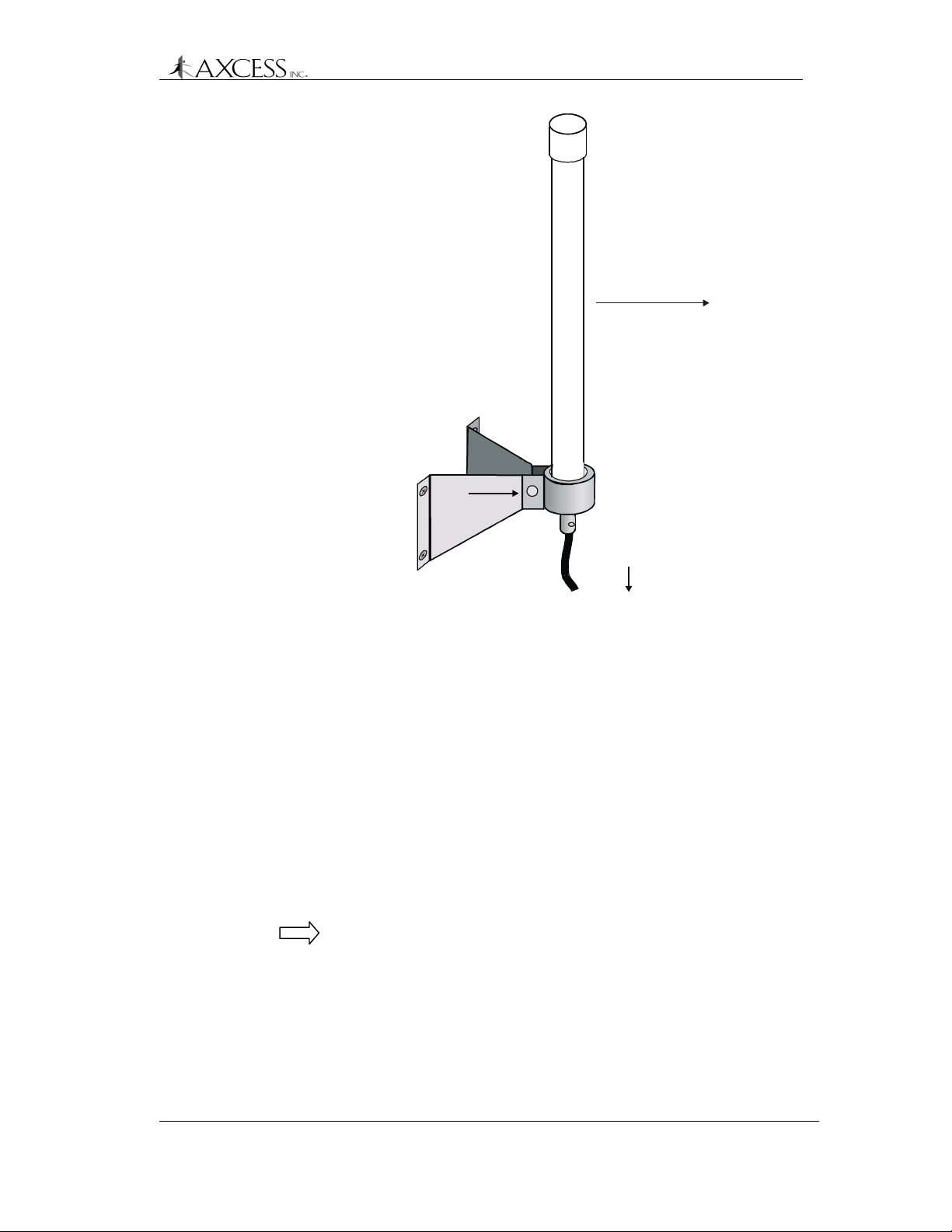
Mounted on the
same side of the
road as the Tags
Tightening Bolt
Dipole Antenna Installation
Max distance between
Dipole Antenna and
Road Loop Antenna:
20 feet
Four fee t from
ground surface
Figure 21 Dipole Antenna mounting
Step 2: Measure the cable distance between the Dipole Antenna
and the ATU. It should not exceed 20 feet.
Step 3: Cut a length of cable that equals the cable length
measured and attach the BNC connectors to both ends of
the RG-58/U coaxial cable (See Appendix A: Coaxial
Cable, page 101).
Step 4: Connect one end of the cable to the Dipole Antenna.
If the Dipole Antenna will be exposed to the weather, treat
the connection with RTV rubber silicone sealant after
everything is installed.
Step 5: Connect the other end of the coaxial cable to the Antenna
RX connector on the ATU.
Note: Do not dress-wrap or tie-down the cables until the
system has been tested.
Step 6: Turn on the system and adjust the ATU in accordance with
the instructions in the Maximizing Antenna Performance
with the ATU section, page 73.
© 1999, AXCESSTM Inc. 750.001.003
Revised June 1999
57
Page 58

Dipole Antenna Installation
Optional Dipole Antenna Installation
If the 20-foot cable run to the ATU prevents you from mounting the
Dipole Antenna within specifications. You can run connect the Dipole
Antenna directly to the Reader. Remember to keep the Dipole
Antenna within 20 feet of the Road Loop Antenna.
Step 1: Measure the cable distance between the Dipole Antenna
Step 2: Cut a length of cable that equals the cable length
Step 3: Connect one end of the cable to the Dipole Antenna.
Step 4: If the Dipole Antenna will be exposed to the weather, treat
Step 5: Connect the other end of the coaxial cable to the RX
and the Reader. It should not exceed 100 feet.
measured and attach the BNC connectors to both ends of
the RG-58/U coaxial cable (See Appendix A: Coaxial
Cable, page 101).
the connection with RTV rubber silicone sealant after
everything is installed.
connector on the Reader.
Note: Do not dress-wrap or tie-down the cables until the
system has been tested.
Step 6: Turn on the system and adjust the ATU in accordance with
the instructions in the Maximizing Antenna Performance
with the ATU section, page 73.
58 750.001.003
Revised June 1999
© 1999 AXCESSTM Inc.
Page 59

Road Loop Antenna Installation
Introduction
The Road Loop Antenna is a transmitting antenna that works in
conjunction with the Dipole Antenna. Road Loop Antenna wire is
available in lengths that will accommodate roadways or gate
entrances up to 70-feet in width.
The Figure 22 shows a simplified diagram representing the field
generated by a Road Loop Antenna. In reality, antenna fields are
lobed and asymmetrical, but the longest range will still be along the
longest sides.
Antenna fields are affected by the type of pavement, amount of rebar,
and nearby power lines. For these reasons, it is strongly
recommended that the Road Loop be laid out and tested before it is
permanently mounted.
Figure 22 A Road Antenna transmit field.
Page 60

Road Loop Antenna Installation
Required Materials
IMPORTANT! Have the following materials on hand for the
installation of the Road Loop Antenna:
• Chalk for marking antenna placement
• Concrete nails or duct tape for holding antenna wire down during
initial placement
• Multimeter for continuity check
• A saw for cutting the road surface
• Two 1/8” saw blades with spacer, either abrasive (for asphalt) or
diamond (for concrete)
• A 3 ¼” x 3 ¼” x 4 ½” triangular wood template for cutting corners
• Vacuum or compressed air for cleaning the cut
• A thin dowel for pressing the Road Loop antenna into the cut
• Road sealant - AXCESS recommends Flexible Embedding
Sealer (P-606) supplied by Bondo Corporation. As a substitute,
you can use either 3-M’s Detector Loop Sealant or Q-Seal
sealant.
Prerequisite Tasks
IMPORTANT! To ensure proper system operation, do not substitute
antenna kit components. Road Loop Antenna wire must be ordered
in specific sizes.
The following tasks need to be completed before proceeding with the
Road Loop Antenna installation:
The ATU has been installed
The Reader has been installed.
The Dipole Antenna has been installed
All connector/coax cabling (except for Road Loop) is complete.
If applicable, the Wiegand or other controller has been
installed. If not, refer to the Original Equipment Manufacturer’s
(OEM) manuals.
Ensure that there is no power-line interference directly under the
road surface.
IMPORTANT! Before permanently installing the Road Loop Antenna,
lay out and test the entire NT132 system.
60 750.001.003
Revised June 1999
© 1999 AXCESSTM Inc.
Page 61

Road Loop Layout & Connecting to the ATU
Step 1: If used for gate access, position the Road Loop Antenna
far enough before the entrance to allow the gate to be fully
open by the time a vehicle reaches it. The gate will be
activated when the Tag is over the Road Loop.
Step 2: If there is a safety loop for the gate, do not use the same
cut. Placing the Road Loop with the safety loop will change
the inductance of the Road Loop. If they are installed on
top of each other, there will be interference between them
and neither is likely to operate properly.
Reader
ATU
Road Loop Antenna Installation
Antenna
Mounted on same
side as Tags
Max distance
between Dipole Antenna
and Road Loop Antenn a:
Minimum distance
between Dipole Antenna
and ground surface:
4 feet
Step 3: Mark the outline of the antenna (yellow contractor’s
Dipole
Max lead-in wire length:
20 feet
20 feet.
Max cable length between Reader
and ATU: 80 feet
Road Loop Antenna
direction of traffic
¼ inch saw cut
Dimension A
Slightly less than
width of the lane
Figure 23 Road Loop Antenna installation diagram
crayon, chalk, etc.). For neatness, ensure that the sides of
the loop rectangle are parallel or perpendicular to
surrounding buildings, fences, etc., as appropriate and
ensure that the corners are 90 degrees.
Dimension B
4 feet
The long sides (Dimension A, Figure 23) will measure the
actual width of the antenna purchased (i.e., 14 feet, 20
feet, 26 feet, etc.) and be slightly shorter than the width of
the road.
IMPORTANT! The short sides (Dimension B) of the road
loop antenna should always measure 4 feet.
Step 4: If necessary, drive square concrete nails (or similar) into
the road surface at the corners to provide the proper
© 1999, AXCESSTM Inc. 750.001.003
Revised June 1999
61
Page 62

Road Loop Antenna Installation
Step 5: Feed one end of the Road Loop wire to the ATU.
Step 6: Insert the end of the Road Loop wire at the ATU into one
Figure 24 Attaching Road Loop wire to the post-to-BNC
rectangular shape to the antenna when laying down the
wire.
IMPORTANT! The total length of lead-in wire (the Road
Loop wire from the Road Loop to the ATU) must not
exceed 20 feet. Do Not Twist the wire as you run it from
the Road Loop to the ATU.
side of a binding post-to-BNC connector (Figure 24).
Tighten the binding post terminal to secure the lead.
Road Loop Lead-in
Do not attach yet
Dual binding post-toMale BNC Connector
connector
Step 7: Connect the BNC-end of the Road Loop wire to the
Antenna TX connector on the ATU.
Step 8: Carefully feed Road Loop wire on toward the loop marked
on the roadway. Secure the wire with duct tape as you
proceed.
Step 9: At the loop feed point, begin to lay wire around the loop
(using the concrete nails to maintain the corners). Again,
secure the loop to the surface with duct tape.
Step 10: When back to the feed point, continue around the loop a
second time if the Road Loop is shorter than 36 feet (do
not allow the two wires to twist) and return to the feed
point.
IMPORTANT! For a Road Loop wider than 36-feet, use
only a single loop of wire.
Step 11: After one or two complete loops (see note above),
continue to lead the wire back to the ATU or junction point.
Do not allow the wires to twist.
Step 12: Carefully review the installation to this point. If everything
is correct, cut away the excess wire, trim and attach the
other end of the Road Loop wire to the other half of the
binding-post-to-BNC connector (Figure 25).
62 750.001.003
Revised June 1999
© 1999 AXCESSTM Inc.
Page 63

Road Loop Antenna Installation
Road Loop Lead-in
Dual binding post-toMale BNC Connector
Figure 25 Post to Male BNC Connector
Step 13: If any third-party equipment will also be installed, lay it out
at this time.
Step 14: Turn on the system and adjust the ATU according to the
instructions in the Maximizing Antenna Performance with
the ATU section, page 73.
Step 15: Using an LED Test Tag, ensure that the transmit field of
the Road Loop extends 7 or 8 feet above ground level and
15 to 24 feet horizontally. The Road Loop Antennas with
greater widths have larger fields.
Step 16: After ensuring proper operation, remove the wire loop and
concrete nails to allow cutting the groove into the roadway.
Common Layout Problems
If the transmit field of the Road Loop Antenna does not have the
proper range, check the following:
• Is there power-line interference (or similar) directly under the
roadbed? If so, the Road Loop Antenna may have to be moved.
• Has part of the Road Loop Antenna inadvertently been twisted?
If so, correct the condition.
• Does lack of continuity with a multimeter indicate a break in the
loop or lead-wire? If so, correct the condition.
• Have all connectors been correctly installed? This is frequently
the cause of problems. Correct if necessary.
• After checking these items, re-check the ATU tuning again.
© 1999, AXCESSTM Inc. 750.001.003
Revised June 1999
63
Page 64

Road Loop Antenna Installation
Installing the Road Loop Antenna
A normal antenna installation should take about two hours using a
walk-behind concrete saw with an abrasive blade to cut asphalt. Two
1/8" blades with a spacer will be required.
The same antenna should take about three hours to cut in concrete
using a diamond cut blade. Two 1/8" blades with a spacer will be
required.
Step 1: Confirm that the loop is correctly marked on the road
surface.
Step 2: Lay out the 45-degree corner cuts. It is helpful to create a
template with the dimensions 3¼” x 3¼” x 4½” (Figure 26).
3 ¼
in
c
h
es
4 ½ inches
Figure 26 Plywood corner template
Do NOT intersect
these cuts!
4 ½ inch side of
plywood template
Saw cuts
Figure 27 Using the template to mark corner cuts
Step 3: At the corner closest to the ATU, mark your lead-in cut.
Step 4: Review your progress one last time for correctness.
64 750.001.003
Revised June 1999
© 1999 AXCESSTM Inc.
Page 65

Road Loop Antenna Installation
Step 5: Cut a groove that is at least a ¼” wide with the concrete
saw. Set the cutting depth to a minimum of 1 ½” deep.
IMPORTANT! Do not let the corners intersect when
sawing. You could cut out a chunk of pavement!
When sawing the corner cuts, cut approximately 1” to 1½”
past the loop sides. This will maintain the saw cut depth at
the 45-degree turn.
Step 6: Use vacuum or compressed air to thoroughly clean out the
groove.
Step 7: Insert the loop and lead-in into the cut grooves. Do not
use a metal object to push the antenna loop into the saw
cut. A tongue depressor or pencil eraser works well.
Step 8: Test the system.
Step 9: Dress and/or tie-wrap all cables and seal all exterior BNC
connections with rubber silicone sealant.
Step 10: Seal the cut with an antenna loop sealant, for example,
Bondo Flexible Embedding Sealer (P-606), 3M Detector
Loop Sealant or Q-Seal sealant. It takes about a gallon of
“Bondo” to seal the cuts from a 16-foot antenna.
© 1999, AXCESSTM Inc. 750.001.003
Revised June 1999
65
Page 66

Page 67

Bar Antenna System Installation
A
Introduction
The Bar Antenna typically receives signals transmitted by personnel
and asset Tags (transponders). The Bar Antenna is an excellent
antenna for mounting above or beside a doorway (sometimes above
the ceiling tile) to monitor or control access to an entry/exit point of a
facility.
Antennas of this type radiate RF energy most efficiently in a direction
broadside to the antenna – and radiating less energy off the edges
(Figure 28). Partial rotation of the antenna forward or backward, and
from side-to-side will produce noticeable results.
Direction of
maximum
signal r adiation
Wall
Edge View of Bar
ntenna
Figure 28 Bar Antenna signal radiation
To ensure proper system operation, do not substitute antenna
components.
Page 68

Bar Antenna System Installation
Required Materials
IMPORTANT! The following materials should be on hand for the
installation of the Bar Antenna:
• RG-58/U coaxial cable with 50 ohm impedance (nominal), solid
copper center conductor, 55% tinned copper braid or better,
100% foil shield coverage (for example, Belden 9310) of
sufficient length to reach the ATU. The maximum recommended
cable length is 20 feet.
• 2 three-piece crimp type male BNC connectors – see page 85 for
installing BNC connectors
• Three-blade rotary coaxial cable stripper
• Phillips and flathead screwdrivers
• Step ladder for positioning the Bar Antenna above the door or
ceiling.
Prerequisite Tasks
The following tasks should be completed:
The ATU has been installed. If not, refer to the appropriate
section in this document and install the ATU before continuing
with the Bar Antenna installation.
The Reader has been installed. If not, refer to the appropriate
section in this document and install the Reader before continuing
with the Bar Antenna installation.
IMPORTANT! Before permanently installing the Bar Antenna, lay out
and test the entire NT132 system.
Installation Considerations
Determine the approximate installation site of the Bar Antenna and of
any third-party gate controller if one is being used. Use the following
guidelines:
• The ATU should be located no more than 20 feet (cable length)
from the antenna. A good location is directly above the doorway
where the Bar Antenna is to be installed – above the ceiling tiles
if desired, but accessible for tuning (Figure 29)
• The Bar Antenna should be located at least 4 inches from any
metal.
68 750.001.003
Revised June 1999
© 1999 AXCESSTM Inc.
Page 69
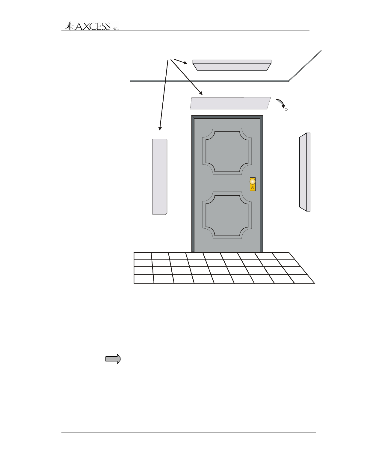
Bar Antenna
Bar Antenna
Positions
Positions
4th Choice
4th Choice
Bar Antenna System Installation
1st Choice
1st Choice
2nd Choice
45
45
e
e
c
c
i
i
o
o
h
h
C
C
d
d
r
r
3
3
Figure 29 Installation points for the Bar Antenna
• Orient the Bar Antenna so that the radiation field provides
maximum coverage of the access or monitoring area (door), etc.
Keep in mind what will be tracked with the antenna – personnel
would carry Tags in their shirt or pants pocket, Tags on laptops
would be carried closer to the floor. The read-range for the Bar
Antenna is about 8 to 12 feet.
IMPORTANT! Test each position shown in Figure 29. Tilting the
Bar Antenna may also improve performance.
If mounting the Bar Antenna on the ceiling, mount it flat with the
front of the case pointing at the floor.
• If applicable, follow the guidelines in the manufacturer’s
documentation for placement and wiring of any controller or
peripheral device.
© 1999, AXCESSTM Inc. 750.001.003
Revised June 1999
69
Page 70

Bar Antenna System Installation
Installing the Bar Antenna
Step 1: Measure the cable run distance between the ATU and the
Step 2: Attach the BNC connectors to each end of both cables.
Step 3: Connect one end of the cable to the female BNC
Step 4: Connect one end of the cable to the female BNC
Step 5: Apply power to the Reader. See the Connecting Power to
Bar Antenna and cut two lengths of RG-58/U coaxial
cable.
connector labeled RX on the back of the Bar Antenna and
connect the other end to the BNC connector on the ATU
labeled RX Antenna.
Note: Do not dress-wrap or tie-down the cables until the
antenna has been permanently installed and the system
has been tested.
connector labeled TX on the back of the Bar Antenna and
connect the other end to the BNC connector on the ATU
labeled TX Antenna.
the Reader – All Types section, page 32.
Step 6: Tune the ATU in accordance with the instructions in the
Maximizing Antenna Performance with the ATU section,
page 73.
Step 7: Test various Antenna locations by positioning the LED
Test Tag at strategic points, i.e., along the edges of the
doorway, along the floor – ensuring complete coverage of
the doorway or monitoring zone.
Step 8: Attach the open Bar Antenna base to wall using supplied
anchors and screws. If you want to install the Bar Antenna
at the optimal angle, wood wedges or flexible metal
brackets can be used.
Step 9: Place the plastic cover over the base and align holes on
the sides of the case and cover.
Step 10: Insert the rivet bases through aligned holes.
Step 11: Insert plastic screws into the rivet bases and push until the
screws are tight.
Step 12: Tighten the screws with a hand-held screwdriver.
Step 13: The plastic rivets are removable with a screwdriver if it is
ever necessary to open the Bar Antenna case.
70 750.001.003
Revised June 1999
© 1999 AXCESSTM Inc.
Page 71

Swing Frame Antenna System Installation
Introduction
A Swing Frame Antenna allows you to mount an antenna in plain
sight without detracting from office surroundings. In a Swing Frame
Antenna, the transmitting and receiving antennas are built into a
picture frame. You can place a picture of your choosing in the frame
and hang the Antenna on the wall near the access or monitoring
point.
Required Materials
IMPORTANT! The following materials are necessary for the
installation of the Swing Frame Antenna:
• RG-58/U coaxial cable with 50 ohm impedance (nominal), solid
copper center conductor, 55% tinned copper braid or better,
100% foil shield coverage (for example, Belden 9310) of
sufficient length to reach the ATU. The recommended maximum
length is 20 feet.
• 4 3-piece crimp type male BNC connectors – see page 85 for
installing BNC connectors
• Three blade rotary coaxial cable stripper
• Four mounting screws
• Phillips and flathead screwdrivers
Prerequisite Tasks
The following tasks should be completed:
The ATU has been installed. If not, refer to the appropriate
section in this document and install the ATU before continuing
with the Swing Frame Antenna installation.
The Reader has been installed. If not, refer to the appropriate
section in this document and install the Reader before continuing
with the Swing Frame Antenna installation.
IMPORTANT! Before permanently installing the Swing Frame
Antenna, lay out and test the entire NT132 system.
Installing the Swing Frame Antenna
Step 1: Cut two coaxial cables with sufficient length to connect the
Swing Frame Antenna to the ATU. The cable lengths
should not exceed 20 feet.
Page 72

Swing Frame Antenna System Installation
Step 2: Attach BNC connectors to both ends of each cable.
Step 3: Attach the RX connector on the back of the Swing Frame
Antenna with the RX Antenna connector on the ATU.
Step 4: Attach the TX connector on the back of the Swing Frame
Antenna with the TX Antenna connector on the ATU.
Step 5: Position the antenna in its approximate final location – but
do not permanently install it at this time. Have a helper
hold the antenna in various positions until maximum
coverage is achieved.
Step 6: Test the system by positioning the LED Test Tag at
strategic points to ensure complete coverage. It will light
up and flash when it is within the field.
Step 7: Apply power to the Reader. See the Connecting Power to
the Reader – All Types section, page 32.
Step 8: Tune the ATU. See the section Maximizing Antenna
Performance with the ATU, page 73.
Step 9: Permanently mount the Swing Frame on the wall using the
mounting holes at the bottom and top of the frame and
dress/tie-wrap all cabling.
72 750.001.003
Revised June 1999
© 1999 AXCESSTM Inc.
Page 73

Maximizing Antenna Performance with the
ATU
Because the antenna transmits by inductive coupling at low
frequency, it is subject to environmental detuning, due to where the
antenna is mounted, what material it is mounted on, etc.
For this reason, it is impossible to factory pre-tune antennas for
optimized generation of the wakeup signal.
Currently, ATUs have one of two methods of adjustment - toggle
switch or jumper. While the methods for adjusting performance are
different, the ATUs are functionally the same.
Adjusting Antenna Performance
Step 1: Apply power to the Reader.
Step 2: Open the Reader. Ensure that the card stack has four
LEDs lit and is emitting a ticking sound.
Step 3: Open the ATU cover. NOTE! You will see either a toggle
switch and rotary dial (Figure 30) or a series of 11 jumpers
(Figure 33). To tune an ATU with jumpers, see page 75.
Rotary Switch
TX Reader
SECONDARY TUNING
Header
3-Position Toggle Switch
1 0 2
PRIMARY TUNING
1
RX Antenna
H1
1
RX Reader
0
0
D.C . VOLTS
5
10
15
TX Antenna
Figure 30 ATU with toggle and rotary switches
Page 74

Maximizing Antenna Performance with the ATU
Adjusting Performance with a Toggle Switch ATU
Step 1: IMPORTANT! Ensure that the wires running from the
toggle switch are plugged into the header. This
sometimes disconnects during shipping. The connector
should be oriented such that position 1 on the rotary dial is
connected to pin 1 on the header (Figure 30).
Step 2: Put the toggle switch into position 0, turn the rotary switch
knob, and watch the voltage meter. Note the position that
provides the peak voltage level on the voltage meter (if
any).
Optimum Tuning
0
0
5
10
15
D.C. VOLTS
Figure 31 Voltage meter showing optimum tuning
Step 3: Repeat Step 2 with the toggle switch in positions 2 and 1.
There are a total of 30 combinations available (10
positions on the rotary switch, and 3 on the toggle switch)
for determining optimum tuning. Check all positions for
peak meter level.
Step 4: Reset the positions of the rotary dial and the toggle switch
that gave the highest voltage on the meter (0 to 4 volts). 1
to 2 volts is a typical optimum reading.
Note: The ATU must be mounted with its connectors
pointing down for the voltmeter to read accurately.
74 750.001.003
Revised June 1999
© 1999 AXCESSTM Inc.
Page 75

Maximizing Antenna Performance with the ATU
Adjusting Performance with a Jumper ATU
When you open the ATU, the jumpers will be in the positions shown
in Figure 33. The goal is to set the jumpers so that largest voltage is
produced, as shown by the strength of the five LEDs.
Jumpers can be placed in one of two positions on a header:
1
Inactive
1
Active
Figure 32 Jumper positions on a header. Pin 1 is labeled.
Inactive – jumper is placed on pins 1 and 2.
Active - jumper is placed on pins 2 and 3.
The various headers control different types and numbers of
capacitors:
Jp1 through Jp9 – each header adds/removes a small
capacitor (0.01 µF) to/from the circuit.
Jp10 – adds/removes one big capacitor (0.1 µF) to/from the
circuit.
Jp11 – adds/removes two big capacitors to/from the circuit.
Step 1: Ensure that all jumpers are placed in the Inactive position.
Step 2: On header Jp1, place the jumper in the Active position
and watch the LEDs.
When tuned correctly, LEDs 1 through 4 will be strongly
strobing, and LED 5 will be flickering, showing a strong
signal. Make note of the jumper positions that create this
display.
Step 3: On header Jp2, place the jumper in the Active position
and watch the LEDs for a strong signal.
Step 4: One at a time, place the jumper in the Active position on
headers Jp3 through Jp9 and watch the LEDs for a strong
signal.
Step 5: Place all jumpers in the Inactive position on all the
headers.
Step 6: On header Jp10, place the jumper in the Active position.
Step 7: One at a time, place the jumper in the Active position on
headers Jp1 through Jp9 and watch the LEDs for a strong
signal.
© 1999, AXCESSTM Inc. 750.001.003
Revised June 1999
75
Page 76

Maximizing Antenna Performance with the ATU
Jp1
Jp11
1
Jp10
1
1
12345
LEDs
Strongest signal
Jp2
111
1
1
Jp9
Jp8
1
position
Jumper in active
position
Jumper in inactive
Jp7
Jp6
Jp5
Jp4
Jp3
TX Antenna
RX Antenna
RX Reader
TX Reader
Figure 33 ATU with jumpers in original positions
Step 8: Place jumpers in the Inactive position on all the headers.
Step 9: On header Jp 11, place the jumper in the Active position.
Step 10: One at a time, place the jumper in the Active position on
headers Jp1 through Jp9 and watch the LEDs for a strong
signal.
Step 11: Place jumpers in the Inactive position on headers Jp1
through Jp9, keeping the jumper on header Jp 11 in the
active position.
Step 12: Place the jumper in the Active position on header Jp10.
Step 13: One at a time, place the jumper in the Active position on
headers Jp1 through Jp9 and watch the LEDs for a strong
signal.
Step 14: When you have tested all the positions, reset the jumpers
to the position that gave the strongest voltage as indicated
by the strength of the LED lights.
76 750.001.003
Revised June 1999
© 1999 AXCESSTM Inc.
Page 77
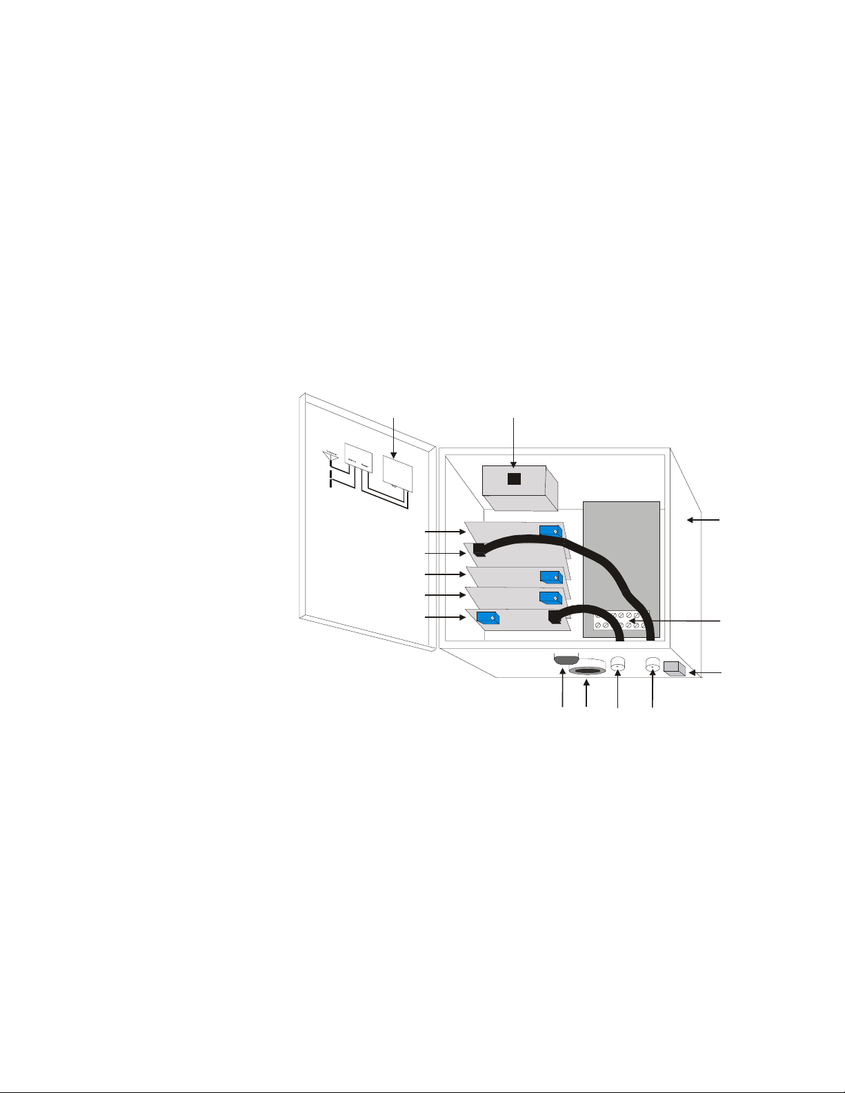
Modifying Antenna Range: Adjusting the
Transmitter Card
Introduction
Each Reader contains a card stack that has five sub-boards, each of
which has a specific function. The transmitter card controls the
voltage output to the transmit antenna. If the Reader’s connectors are
at the bottom, then the transmitter card is on the bottom of the stack
(Figure 34). This card also can be identified by the faint chirping
sound it makes and the cable that goes to the TX connector on the
outside of the Reader.
Cabling Label
Unilon RX Card
RF Card
Unilon Output Card
Unilon TX Card
Transmitter Card
RJ-45
Conduit
Chase
TX
RXRS-232
Figure 34 Reader – Internal View
The transmitting antenna puts out a “wakeup” field that activates
Tags entering that field. The area of Tag activation can be controlled
by adjusting the size of the transmit field. By turning down the voltage
to the transmit antenna, you shrink the transmit field. This is useful
when a transmission field extends beyond its desired area. For
example, you may want to shrink a transmission field for a Road
Loop so that the size of the field is only a lane wide. This prevents
accidental activation of Tags in another lane – for instance, a parking
garage with entrance and exit gates right next to each other.
Reader Case
T erminal Block (TB1)
Ground Lug
Page 78

Modifying Antenna Range
Note: Each Reader is shipped from the factory with the voltage level
adjusted to its highest level.
Required Materials
The following materials are necessary for successful adjustment of
the transmission field:
• A very small flathead screwdriver
Adjusting the Transmission Field
The output voltage is controlled by the blue adjustable pot on the
transmitter card. This pot is a thirty-turn pot -- it can rotate in one
direction 30 times. After it has been rotated 30 times, it will make a
soft clicking sound as it is turned, indicating that the pot can no
longer be turned in this direction and have an effect. When you hear
this sound, the transmitter card has been adjusted to one extreme or
the other.
IMPORTANT! There are four blue adjustable pots in the card stack.
Refer to Figure 34 to ensure that you tune the correct one.
To lower the voltage level and reduce the transmission field Rotate the pot clockwise. The volume of the chirping will also be
reduced. Constantly check the field to ensure that it has the range
that you want.
IMPORTANT! The system will stop functioning if the voltage is
turned down too low. To fix this, turn the pot counter-clockwise until
the pot clicks and the chirping from the transmitter card can be
heard. Then back the field down again without turning off the voltage
to the system.
To increase the voltage level and enlarge the transmission field
- Rotate the pot counter-clockwise. The volume of the chirping will
also increase. When the pot makes a clicking noise it has been
turned up as high as possible.
When you have adjusted the field, retune the ATU. See the
chapter Maximizing Antenna Performance with the ATU, page 73.
78 750.001.003
Revised June 1999
© 1999 AXCESSTM Inc.
Page 79

Tag Mounting
Because of the low frequency used for transmission, Tags can be
mounted in a variety of positions on assets and vehicles without the
signal being blocked. Personnel can carry Tags on chains, clips,
pockets or purses.
Mounting Tags to Assets
Required Materials
• LED Test Tag
• Mounting materials for asset Tags – cyanoacrylate (ProCement
from ProTec Technology, Super Glue), MEK (methyl ethyl
ketone), double-sided tape, or a Mylar enclosure that has a sticky
back
• Latex gloves if you are using one of the above adhesives
• Washable marker or pencil
IMPORTANT! Before using either cyanoacrylate or MEK, consult the
vendor’s instructions and the compound’s Material Safety Data
Sheet.
For all assets, mount the Asset Tag with the flat side attached to the
asset.
Mounting a Tag to a Laptop Computer
Some electronic devices (for example, laptop computers) generate
radio frequency emissions (noise) that may activate 2.0 Tags,
causing them to transmit. This unintended wakeup and transmission
could result in unnecessary battery drainage. 3.0 Tags, although they
may wake up, will recognize the wakeup frequency as noise and will
not transmit.
Use the following procedure for mounting a Tag to a laptop:
Step 1: Turn on the laptop and ensure that the screen is on.
Step 2: Position the cover so that it is in a comfortable working
position.
Step 3: Place the LED Test Tag flat side down on the outside of
the laptop.
Step 4: Observe the LED Test Tag as you slide it on the laptop
cover – find a location that does not activate the LED.
Step 5: Ensure that when the Tag is mounted, it will not interfere
with a docking station.
Page 80

Tag Mounting
Step 6: IMPORTANT! Ensure that the Tag can be read by the
Reader when the laptop is carried normally through the
transmit field. In addition, place the Tag on the laptop
where it cannot be easily pried off or removed. Do not
place the Tag on a removable surface (i.e., battery cover).
Step 7: Once a location is found, use a pencil to trace around the
edge of the LED Test Tag.
Step 8: Use a cyanoacrylate adhesive (for example, ProCement
from ProTec Technology). Practice the following steps with
similar materials of lesser value until the proper amount of
adhesive and application pressure is established.
Step 9: Closely follow the instructions provided with the adhesive
kit. You may have to lightly sand the surface inside the
marked area if the asset is painted or has a protective
surface applied.
Step 10: Wearing latex gloves, thoroughly clean the sanded area
with the supplied isopropyl alcohol pad.
Step 11: Carefully apply adhesive to the back of the Tag that will be
bonded to the asset. Ensure a continuous bead close to
the edge, but not so thick that the excess will ooze beyond
the edge once the Tag is positioned.
Step 12: Carefully position the Tag onto the marked area of the
asset, applying pressure for the time specified in the
instructions.
Note: Only an extreme level of prevention is a guarantee against loss
or damage at the hands of a determined thief. However, when assets
are tagged as described here, they will remain tagged for tracking
purposes even under heavy industrial or business usage.
80 750.001.003
Revised June 1999
© 1999 AXCESSTM Inc.
Page 81

Mounting Tags to Vehicles
Required Materials
• LED Tag
• Mounting materials – Velcro tape, double-sided tape, Mylar
enclosure
• Washable marker or pencil
Mounting locations
The first choice for mounting a Tag in a vehicle is on the upper left or
upper right side of the back window. Tags should be mounted on the
side that is closest to the Dipole Antenna.
Other mounting places include the lower right or left corner of the
windshield, behind the rearview mirror, and above either the right or
the left visor.
IMPORTANT! Placing a Tag directly on the dashboard in very hot
climates is not recommended.
Tag Mounting
Testing for the Best Tag Location
This test is primarily for Tags that need to be mounted in the front
windshield area. This test may not be necessary for back window
mounting.
Step 1: With the car out of range of the Road Loop Antenna, sit in
the car and locate a spot about 3 inches from the
dashboard and hold LED test tag there.
Step 2: Turn on the car while watching the LED to see if it turns
on. (Note: this usually happens only in older vehicles with
very noisy alternators.)
Step 3: If the Tag turns on, move the tag up ½ inch and repeat test
until the Tag no longer turns on.
Step 4: Mark the spot you found on the windshield with some
scotch tape or a washable marker.
Note: The LED light can be hard to see in bright daylight.
Shield the LED with your hand while holding it against the
windshield.
Step 5: Test the various positions to find the one that works best
for your installation and the vehicles involved.
© 1999, AXCESSTM Inc. 750.001.003
Revised June 1999
81
Page 82

Tag Mounting
Mounting a Vehicle Tag
Step 1: Apply mounting tape/Velcro on the back of the Tag (Figure
35). Push the mounting tape/Velcro securely on the back
of the Tag.
Figure 35 Back of a Tag
IMPORTANT! To receive maximum range from the
antenna, the Tag must be mounted with the back of the
Tag facing the glass at least 3 inches off the dashboard.
Step 2: If using Velcro, apply one side of the Velcro mount to the
location where the LED Tag was successfully tested. Then
mount the Tag with the other piece of Velcro onto the
Velcro on the windshield.
Figure 36 Velcro applied to window
Step 3: If using double-sided tape, peal the cover off the double-
sided tape attached to the Tag. Firmly apply the Tag to the
windshield location you found earlier and press the Tag to
the windshield ensuring solid contact.
82 750.001.003
Revised June 1999
© 1999 AXCESSTM Inc.
Page 83

Tags and Personnel
Tag Mounting
Required Materials
• Mounting materials – clips, chains, etc.
Personnel Tags can be threaded onto a chain, placed in a pocket, or
hooked on a clip. A picture ID card can fit in the Tag’s recess.
© 1999, AXCESSTM Inc. 750.001.003
Revised June 1999
83
Page 84

Page 85

Troubleshooting the System
Introduction
The purpose of this chapter is to determine which portion of the
system is not functioning and to provide guidelines for fixing the
problem.
Required Materials
The following materials are necessary for troubleshooting:
• LED Test Tag
• A regular Tag
• Tape measure for measuring fields and cable
• A computer for interfacing directly with the Reader – a laptop is
ideal
• A terminal emulation application such as HyperTerminal
• A one-to-one Serial cable with a DB9 male connector
• Multimeter
Check the Power
Step 1: Open the Reader case. The LEDs on the PCB card stack
should be lit, indicating that power is supplied. If the LEDs
are not lit, check your power connections. If the Reader is
driving relays, use the multimeter to ensure that the total
power draw is below 200 mA.
Step 2: Open the ATU case. If you have a toggle switch ATU, the
voltage meter should indicate some voltage – between 1.0
V and 5.0 V. If you have a jumper ATU, then the LEDs
should be lit. If you do not have power to the ATU, check
the cables from the Reader to the ATU. The ATU receives
its power from the Reader via the RG-58/U cable. This is
one reason this cable is specified for the NT132 system.
Page 86

Troubleshooting the System
Check the Site
Step 1: Ensure that there are no other sources of similar radio
Step 2: Determine if metal is attenuating the signal. If a Road Loop
Step 3: Check the cable lengths – there should be a maximum of
Step 4: Ensure that the system is protected from the elements.
frequencies nearby. Proximity card readers and clicker
systems can affect the NT132 system, as can radiocontrolled sprinkler systems and military-grade
communications systems.
is mounted in concrete, rebar can impact performance. If a
Dipole Antenna is mounted less than six inches away from
metal, it will lose reception range. If the antennas are too
close to metal, move them away.
80 feet between the Reader and the ATU and 20 feet
between the ATU and antennas. If the cables are too long,
they will need to be shortened.
Exposed equipment should be waterproofed.
Trace the Cables
Step 1: Trace the cable from the transmitting antenna to the TX
Step 2: Trace the cable from the TX Reader connector on the
Step 3: Trace the cable from the receiving antenna to the RX
Step 4: Trace the cable from the RX Reader connector on the
Check the Connectors
Step 1: Ensure that the connectors are not free spinning.
Step 2: Replace any connectors on cables that freely spin.
ANTENNA connector on the ATU.
ATU to the TX connector on the Reader.
ANTENNA connector on the ATU
ATU to the RX connector on the Reader.
86 750.001.003
Revised June 1999
© 1999 AXCESSTM Inc.
Page 87

Check the Antennas and Cables for Continuity
Continuity is a direct connection or dead short between two points on
a cable. Continuity can expose bad cables or problems with
connections.
Step 1: Turn off the power to the Reader.
Step 2: Disconnect all the cables between the Reader, the ATU
and the antennas.
Step 3: Check each cable for continuity. If continuity is present in a
cable, then the cable is shorted. Redo the cable.
Reception
The reception portion of the system should not exhibit continuity. If
continuity is found during any of the following steps, fill out the
Customer Support Questionnaire (page 107) and call Customer
Support at 1-800-577-6080.
Step 4: Check the RX connector on the Reader for continuity. If
there is continuity, then there is a problem with the
Reader.
Troubleshooting the System
Step 5: Connect the coax cable from the RX connector on the
Reader to the RX Reader connector on the ATU and
check for continuity in the RX Antenna connector. If there
is continuity, then there is a problem with the ATU.
Step 6: Check the RX connector on the antenna for continuity. If
continuity exists, then there is a problem with the antenna.
Step 7: Connect the coax cable from the receiving antenna to the
RX Antenna connector on the ATU. If there is continuity,
then there is a problem with the ATU.
Transmission
The transmission portion of the system should have continuity. If
continuity is not present, then follow the directions given for each
step.
Step 8: Check the TX connector on the Reader for continuity. If
continuity does not exist, there is a problem with the
Reader. Fill out the Customer Support Questionnaire
(page 107) and call Customer Support at 1-800-577-6080.
Step 9: Connect the coax cable to the TX connector on the
Reader and check for continuity at the other end. If there is
no continuity, the cable is bad. Redo the cable.
Step 10: Connect the other end of the coax cable to the TX Reader
connector on the ATU and check for continuity in the TX
Antenna connector. If continuity does not exist, then there
is a problem with the ATU. Fill out the Customer Support
© 1999, AXCESSTM Inc. 750.001.003
Revised June 1999
87
Page 88

Troubleshooting the System
Road Loop Antenna
Step 11: Test a Road Loop Antenna for continuity by checking both
Step 12: Plug the antenna into the BNC banana connector and test
Step 13: Plug the BNC banana connector into the TX Antenna
Questionnaire (page 107) and call Customer Support at 1800-577-6080.
ends of the antenna. If continuity does not exist, there is a
problem with the Road Loop. Fill out the Customer
Support Questionnaire (page 107) and call Customer
Support at 1-800-577-6080.
for continuity. If continuity does not exist, the banana
connector is faulty. Replace the banana connector.
connector on the ATU. Check for continuity on the TX
Reader connector. If continuity does not exist, there is a
problem with the ATU. Fill out the Customer Support
Questionnaire (page 107) and call Customer Support at 1800-577-6080.
Bar and Swing Frame Antennas
Step 12: Check a Bar Antenna or Swing Frame Antenna for
continuity by testing the TX connector on the back of the
antenna. If continuity does not exist, fill out the Customer
Support Questionnaire (page 107) and call Customer
Support at 1-800-577-6080.
Step 13: Connect the coax cable to the antenna and check for
continuity at the other end of the cable. If continuity does
not exist, there is a problem with the cable. Redo the
cable.
Step 14: Connect the other end of the cable to the TX Antenna
connector on the ATU and check for continuity on the TX
Reader connector. If continuity does not exist, then there is
a problem with the ATU. Fill out the Customer Support
Questionnaire (page 107) and call Customer Support at 1800-577-6080.
88 750.001.003
Revised June 1999
© 1999 AXCESSTM Inc.
Page 89

Check the ATU
Troubleshooting the System
Step 1: Ensure that the ATU is displaying voltage – either by LEDs
or on the voltage meter. If the voltage is inadequate,
retune the ATU. See the chapter Maximizing Antenna
Performance with the ATU, page 73
Step 2: If you have a Toggle Switch ATU, ensure that the 10-wire
header is properly seated. See the section Adjusting
Performance with a Toggle Switch ATU, page 74.Check
the Transmission Field
Step 1: Check the range specifications for the transmitting
antenna listed in the Appendix B: Specifications chapter,
page 103.
Step 2: Test the range of the transmitting antenna with the LED
Test Tag.
Step 3: If The LED Test Tag does not light, check the power, the
cables and the transmitting antenna. There is also the
possibility that the LED Test Tag is not working. Hook the
Reader to a PC and use another Tag in the field. See the
chapter Configuring 3.x Reader Firmware, page 35.
Step 4: If the range is smaller than desired, then the signal needs
to be adjusted. Be aware however that various
environmental conditions can impact antenna
performance. See the section Maximizing Antenna
Performance with the ATU, page 73.
Step 5: If the range is larger than desired, then the signal needs to
be adjusted. See the section Modifying Antenna Range:
Adjusting the Transmitter Card, page 77.
Step 6: Open the Reader case and listen for the repetitive chirping
emanating from the transmitter board in the Reader. If the
chirp is not heard, retune the transmitter card in the
Reader. See the section Modifying Antenna Range:
Adjusting the Transmitter Card, page 77.
Step 7: If none of the suggested solutions work, fill out the
Customer Support Questionnaire (page 107) and call
Customer Support at 1-800-577-6080.
© 1999, AXCESSTM Inc. 750.001.003
Revised June 1999
89
Page 90

Troubleshooting the System
Check the Reception
If the transmission field is functioning but Tags are not being read,
then there may be a problem with the reception portion of the system.
Step 1: Disconnect the receiving antenna.
Step 2: Attach the Reader to a computer and place it into
Step 3: Place a Tag (ensure that the tag is programmed into the
Step 8: If no Tag information appears on the computer screen,
Step 9: If the Reader is set for the correct version of Tags and
diagnostics mode. See the chapter Configuring 3.x Reader
Firmware, page 35.
system if appropriate – i.e., for Wiegand control panels)
directly on top of the transmitter board in the Reader case.
(Figure 37).
place another Tag on the board. If there is still no output,
check which Tag version the Reader is set to report. See
the section Toggling between reading 3.x Tags and
reading 2.0 Tags page 40.
there is still no output, fill out the Customer Support
Questionnaire (page 107) and call Customer Support at 1800-577-6080.
Cabling Label
Unilon RX Card
RF Card
Unilon Output Card
Unilon TX Card
Transmitter Card
Figure 37 Reader Transmitter Card
RJ-45
Conduit
Chase
TX
Reader Case
T erminal Block (TB1)
Ground Lug
RXRS-232
90 750.001.003
Revised June 1999
© 1999 AXCESSTM Inc.
Page 91

Troubleshooting the System
Check the Output and Connections to Third-Party Devices
If the transmission and reception portions of the system seem fine,
but the output is incorrect or absent, check the connections to the
devices that receive system output.
Serial Reader
Step 1: Ensure that the communication port settings are correct:
Baud Rate 4800
Data Bits 8
Parity None
Stop Bits 1
Flow Control None
Wiegand Reader
Step 1: Ensure that the Wiegand control panel is SIA 26-bit
standard compliant.
Step 2: Ensure that Data Zero, Data One and Ground are wired to
the Wiegand control panel correctly.
Step 3: Ensure that the Tags and site code are entered correctly
into the panel.
FTT Reader
Step 1: Ensure that the Reader is not in diagnostics mode.
Step 2: Ensure that the LonWorks wiring is correct.
Step 3: Ensure that Serial Gateway is connected to the PC and
that the communication port settings are correct:
Baud Rate 2400
Data Bits 8
Parity None
Stop Bits 1
Flow Control None
© 1999, AXCESSTM Inc. 750.001.003
Revised June 1999
91
Page 92

Page 93

Common Problems with NT132
Components
Cable
Problem: The NT132 System has reduced range
Most of the problems encountered with the NT132 system lie with the
cables. This includes having little or no range on the antennas.
Check these items first:
Step 1: Ensure that RG-58/U with 100% foil shield coverage is
used.
Step 2: Ensure that the cable lengths are within specifications: no
more than 80 feet between the Reader and the ATU and
no more than 20 feet between the ATU and the antennas.
Step 3: Ensure that the connectors are well fastened and in good
order.
Step 4: Ensure that TX is connected to TX and RX is connected to
RX on the Reader, ATU and antennas.
Step 5: Check the continuity of the cables. See page 87 for details
on checking continuity.
Power
Problem: The NT132 System has no range
Step 1: Check that all LEDs in the Reader are on. LEDs indicate
that the Reader is receiving power.
Step 2: Check that the Reader has power. Information on
providing power can be found on page 32.
Step 3: Use the multimeter to check voltage into the white terminal
block.
ATU
Problem: The ATU meter does not show any voltage
Step 1: Tune the ATU. See page 73 for information.
Step 2: Check if the LEDs in the Reader are on. If not, ensure that
the Reader has been connected to power. Information on
providing power can be found on page 32.
© 1999, AXCESSTM Inc. 750.001.003
Revised June 1999
93
Page 94

Troubleshooting the System
Step 3: Ensure that the 10-wire header is seated properly in the
Step 4: Ensure that RG-58/U with 100% foil shield coverage is
Step 5: Ensure that the cable lengths are within specifications: no
Step 6: Ensure that the connectors are well fastened and in good
Step 7: Ensure that TX is connected to TX and RX is connected to
Step 8: Check the continuity of the cables. See page 87 for details
Problem: The ATU meter oscillates but will not adjust
Step 1: Ensure that the 10-wire header is seated properly in the
ATU. See page 74 for a discussion of seating the header.
used.
more than 80 feet between the Reader and the ATU and
no more than 20 feet between the ATU and the antennas.
order.
RX on the Reader, ATU and antennas.
on checking continuity.
Toggle Switch ATU. See page 74 for a discussion of
seating the header.
Road Loop Antenna
Problem: The Road Loop Antenna has no range
Step 1: Ensure that RG-58/U with 100% foil shield coverage is
used.
Step 2: Ensure that the cable lengths are within specifications: no
more than 80 feet between the Reader and the ATU and
no more than 20 feet between the ATU and the antennas.
Step 3: Ensure that the connectors are well fastened and in good
order.
Step 4: Ensure that TX is connected to TX and RX is connected to
RX on the Reader, ATU and antennas.
Step 5: Check the continuity of the cables. See page 87 for details
on checking continuity.
Step 6: Check the Road Loop Antenna and the banana connector
for continuity.
Step 7: Ensure that there is not a splice in the Road Loop
Antenna.
Step 8: Ensure that the ATU is tuned properly. See page 73 for
information.
Step 9: Ensure the 10-wire header is seated properly in the Toggle
Switch ATU. See page 74 for a discussion of seating the
header.
94 750.001.003
Revised June 1999
© 1999 AXCESSTM Inc.
Page 95

Troubleshooting the System
Step 10: Ensure the pot on the TX card in the Reader is turned to
maximum output.
Step 11: Ensure that the LEDs on the PCB stack in the Reader are
lit. Information on providing power can be found on page
32.
Step 12: Ensure the TX cable in the Reader is seated properly on
the TX card.
Step 13: Ensure that the layout of the system is within
specifications:
The loop layout 4 feet x ordered width. The Road Loop
should be installed on the right side of the lane and the
longest length should go across the width of the lane.
Number of wraps appropriate for the length of the antenna.
See the section Road Loop Layout & Connecting to the
ATU, page 61, for further information on wrapping the
Road Loop.
Step 14: Check environmental conditions:
No rebar under the Road Loop Antenna.
No power line interference directly above or below the
Road Loop Antenna.
No other RFID systems operating nearby.
Problem: The Road Loop activates Tags in another lane
Step 1: Ensure that the Road Loop is laid out correctly in the lane
– the longest side should go across the width of the lane.
Step 2: Ensure that the Road Loop is installed on the right-hand
side of the lane.
Step 3: Reduce the transmit voltage by adjusting the pot on the
transmit card in the Reader. See the chapter Modifying
Antenna Range: Adjusting the Transmitter Card, page 77.
© 1999, AXCESSTM Inc. 750.001.003
Revised June 1999
95
Page 96

Troubleshooting the System
Dipole Antenna
Problem: The Dipole Antenna has diminished or no range
Step 1: Ensure that RG-58/U with 100% foil shield coverage is
Step 2: Ensure that the cable lengths are within specifications: no
Step 3: Ensure that the connectors are well fastened and in good
Step 4: Ensure that TX is connected to TX and RX is connected to
Step 5: Check the continuity of the cables. See page 87 for details
Step 6: Hook the Dipole Antenna directly to the Reader to test its
used.
more than 80 feet between the Reader and the ATU and
no more than 20 feet between the ATU and the antennas.
order.
RX on the Reader, ATU and antennas.
on checking continuity.
range.
Bar Antenna
Step 7: Swap the nonfunctioning Dipole Antenna with another
Dipole to check if it is a Dipole Antenna problem.
Problem: The Bar Antenna has diminished or no range
Step 1: Ensure that RG-58/U with 100% foil shield coverage is
used.
Step 2: Ensure that the cable lengths are within specifications: no
more than 80 feet between the Reader and the ATU and
no more than 20 feet between the ATU and the antennas.
Step 3: Ensure that the connectors are well fastened and in good
order.
Step 4: Ensure that TX is connected to TX and RX is connected to
RX on the Reader, ATU and antennas.
Step 5: Ensure that the Bar Antenna has been positioned
correctly. The Bar Antenna is for indoor use only.
Step 6: Ensure that the ATU is tuned. See page 73 for information.
Step 7: Check for continuity on the connectors, cable, loop and
dipole. The loop should have continuity. The dipole should
be checked from the end of the dipole to the terminal and
should have continuity. Check to see if continuity goes
from loop to BNC connector. Check Dipole continuity from
terminal block to BNC connector. See page 87 for details
on checking continuity.
96 750.001.003
Revised June 1999
© 1999 AXCESSTM Inc.
Page 97

Step 8: Check the 10-wire header within the Toggle Switch ATU to
Step 9: Check the LEDs within the Reader to be sure they are on.
Step 10: Check the Reader to see if it is connected to a power
Step 11: Check to see if the 30-turn pot adjustment switch is turned
Step 12: Check for any environmental interference affecting the
Swing Frame Antenna
Problem: The Swing Frame Antenna has diminished or no range
Step 1: Ensure that RG-58/U with 100% foil shield coverage is
Troubleshooting the System
be sure that it is seated properly. See page 74 for a
discussion of seating the header.
source. Information on providing power can be found on
page 32.
to the maximum on the TX card in the Reader. See the
chapter Modifying Antenna Range: Adjusting the
Transmitter Card, page 77.
system performance.
used.
Step 2: Ensure that the cable lengths are within specifications: no
more than 80 feet between the Reader and the ATU and
no more than 20 feet between the ATU and the antennas.
Step 3: Ensure that the connectors are well fastened and in good
order.
Step 4: Ensure that TX is connected to TX and RX is connected to
RX on the Reader, ATU and antennas.
Step 5: Ensure that the Swing Frame Antenna has been
positioned correctly. The Swing Frame Antenna is for
indoor use only.
Step 6: Ensure that the ATU is tuned. See page 73 for information.
Step 7: Ensure that the 10-wire connector is well seated in the
Toggle Switch ATU. See page 74 for a discussion of
seating the header.
Step 8: Check for continuity on the connectors, cable and transmit
antenna. The transmit antenna should have continuity.
See page 87 for details on checking continuity.
Step 9: Check the LEDs within the Reader to be sure they are on.
Step 10: Check the Reader to see if it is connected to a power
source. Information on providing power can be found on
page 32.
Step 11: Check to see if the 30-turn pot adjustment switch is turned
to the maximum on the TX card. See the chapter
© 1999, AXCESSTM Inc. 750.001.003
Revised June 1999
97
Page 98

Troubleshooting the System
Step 12: Check for any environmental interference affecting the
Wiegand Reader
Problem: The Wiegand Reader is not working
Step 1: Ensure that the Wiegand Control Panel complies with the
Step 2: Ensure that the internal RX and TX cables are properly
Step 3: Ensure that the RS-232 cable is properly seated.
Step 4: Ensure that the LEDs on the PCB card stack are lit. All but
Step 5: Ensure that the Transmitter card is chirping.
Modifying Antenna Range: Adjusting the Transmitter Card,
page 77.
system performance.
SIA 26-bit standard.
seated.
the Transmitter card should have lit LEDs.
Serial Reader
Step 6: Verify the jumper settings on the Unilon cards against the
information in the manual. See the section Unilon Reset
Buttons, page 45.
Step 7: Ensure that the Reader has power. Information on
providing power can be found on page 32.
Step 8: Ensure that the Wiegand cable to the terminal block is
properly seated.
Step 9: Ensure that the wires are connected correctly to the
Wiegand control panel.
Problem: The Serial Reader is not working
Step 1: Verify the jumper settings on the Unilon cards against the
information in the manual. See the section Unilon Reset
Buttons, page 45.
Step 2: Ensure that the internal RX and TX cables are properly
seated.
Step 3: Ensure that the Transmitter card is chirping.
Step 4: Ensure that the RS-232 cable is properly seated.
Step 5: Ensure that the LEDs on the PCB card stack are lit. All but
the Transmitter card should have lit LEDs.
Step 6: Ensure that the Reader has power. Information on
providing power can be found on page 32.
98 750.001.003
Revised June 1999
© 1999 AXCESSTM Inc.
Page 99

FTT Reader
Troubleshooting the System
Step 7: Ensure that the communications port settings on the serial
device are correct: 4800 baud, eight data bits, no parity,
one stop bit, no flow control.
Problem: The FTT Reader is not working
Step 1: Ensure that the Transmitter card is chirping.
Step 2: Verify the jumper settings on the Unilon cards against the
information in the manual. See the section Unilon Reset
Buttons, page 45.
Step 3: Ensure that the internal RX and TX cables are properly
seated.
Step 4: Ensure that the RS-232 cable is properly seated.
Step 5: Ensure that the LEDs on the PCB card stack are lit. All but
the Transmitter card should have lit LEDs.
Step 6: Ensure that the Reader has power. Information on
providing power can be found on page 32.
Serial Gateway
Tags
Step 7: Ensure that the FTT network wires are properly
connected.
Problem: The Serial Gateway is not working
Step 1: Ensure that the FTT network wires are properly
connected.
Step 2: Ensure that power is provided to the Serial Gateway. See
page 31 for information on how to apply power.
Step 3: Ensure that the communications port settings on the PC
are correct: 2400 baud, eight data bits, no parity, one stop
bit, no flow control.
Problem: The Tags are not being picked up by the system
Step 1: Ensure that the Tags are properly mounted. Tags should
not be mounted in an area that can wake them up when
they are not in the antenna field. They should be mounted
in such a way that they can be activated when they enter
the antenna field.
© 1999, AXCESSTM Inc. 750.001.003
Revised June 1999
99
Page 100

Troubleshooting the System
Step 2: If the Tags are mounted on vehicles, ensure that they are
beige. Black Tags become hotter than beige Tags in direct
sunlight and can warp under extreme conditions.
100 750.001.003
Revised June 1999
© 1999 AXCESSTM Inc.
 Loading...