

Axcera 79XITS-7045 User Manual

ADC
TELECOMMUNICATIONS
TECHNICAL MANUAL
EXHIBIT IV
(PRELIMINARY)
BTS-7010
FREQUENCY AGILE
QAM UPCONVERTER
REV: 0
102 Rahway Road
McMurray, PA 15317 USA
Phone 412-941-1500
FAX 412-941-9421

SYSTEM DESCRIPTION
The Frequency Agile QAM Upconverter (Wavecom Electronics Inc. MA4040D) is a commercial
quality IF upconverter designed for cable, MMDS and LMDS applications. The MA4040D
upconverter operates from 53 to 857 MHz and maintains a phase noise specification that exceeds
the DOCSIS requirements for 64 QAM. The MA4040D is a modular circuit card and operates in
a card chassis (MA4002D)with a common power/control module (MA4011D) and can contain
up to ten (10) MA4040D independent frequency agile upconverters.
The MA4040D functions as the IF to UHF upconverter component of the BTS-7010 system. The
MA4040D inputs the 44 MHz IF from the WMTS and output a 222 – 408 MHz output signal
that is fed to the input of the BTS-7010.

FREQUENCY AGILE 256 QAM
UPCONVERTER
MA4040D
INSTALLATION AND OPERATION GUIDE FOR
SYSTEM OPERATORS

Proprietary to WaveCom Electronics Inc.
All rights reserved.
No part of this publication may by reproduced in any form or by any means or used to make any derivative work (such as translation, transformation
or adaptation) without written permission from WaveCom Electronics Inc.
WaveCom Electronics Inc. reserves the right to revise this publication and to make changes in content from time to time without obligation on the
part of WaveCom Electronics Inc. to provide notification of such revision or change.
WaveCom Electronics Inc. provides this guide without warranty of any kind, either implied or expressed, including, but not limited to, the implied
warranties of merchantability and fitness for a particular purpose. WaveCom Electronics Inc. may make improvements or changes in the
product(s) described in this manual at any time.
MA4040D Manual; MAN1L0901 REV 13(0104); Approved: D.P.
Specifications subject to change without notice — Printed in Canada
WaveCom Electronics Inc
MA4040D Manual; MAN1L0901 REV 13(0104)
Approved: D.P.
ii
Thank-you for purchasing this product
and welcome to WaveCom!
You have chosen an innovative solution from a leading
technology design center in the ongoing TV & data delivery
revolution.
No doubt you’ve been thinking that the future of your television delivery system includes new technologies like
Digital TV, Internet Over Cable, Wireless Cable. By selecting WaveCom, you are benefiting from the same
design powerhouse that since 1988 has created custom RF and digital products for technology leaders like Nortel
Networks, Diva Systems and Cisco Systems.
WaveCom designs and manufactures:
44 Agile CATV Modulators 44 256 QAM Upconverters 44Digital Video Modulators
44 Frequency Translators 44 Spread Spectrum Devices 44 Off-Air Demodulators
44 Video-On-Demand Products 44 Wireless Cable MMDS 44 Wireless Cable LMDS
44 Frequency Stackers 44 MMDS Transceivers 44Satellite Receivers
and more! Designs to fill the market needs of the CATV industry – both foreign and domestic.
For additional product or corporate information, contact us:
On the web at: www.WaveCom.ca
By sending email to: sales@WaveCom.ca
By telephone: (306) 955-7075
By fax: (306) 955-9919
By snail mail: WaveCom Electronics Inc.
222 Cardinal Cres.
Saskatoon, SK Canada S7L 6H8
WaveCom's Corporate Mandate
is to be a leading worldwide designer and manufacturer of state-of-the-
art communications equipment and components. Through the
remarkable success of our customers and business partners,
WaveCom innovations are achieving this goal.
WaveCom Electronics Inc
MA4040D Manual; MAN1L0901 REV 13(0104)
Approved: D.P.
iii

SAFETY PRECAUTIONS
1. Before installing and operating this equipment, read all Safety, Installation and Operating sections. Retain this
manual for future reference.
2. Follow all instructions — Failure to do so may result in damage to the unit or severe personal injury.
3. Servicing should not be attempted by the user. There are no user serviceable parts inside. Refer all servicing to
factory qualified personnel.
4. Shock Hazard — An electrical shock hazard exists when the chassis cover is removed as is required to set
internal controls. Always disconnect power from the unit before removing the cover.
5. Cleaning — Do not use liquid or aerosol cleaners. Use a damp cloth for cleaning.
6. “CAUTION: The WaveCom MA4000D system with the –48 V dc supply option is intended for use only in
rack mounted or cabinet installations where the dc supply wiring is protected from access by user
personnel and from the outside environment.”
Warning Do not work on the system or connect or disconnect cables during periods of lightning activity.
LES PRÉCAUTIONS DE SÉCURITÉ
1. Avant d'installer ou d'opérer cet équipement, lisez, toutes les sections de sécurités, d'installations et
d'opérations. Gardez ce manuel comme source de référence.
2. Suivez toutes instructions - si non, vous risquez d'endommager la machine ou de vous blesser sérieusement.
3. N'essayez, pas de réparer cet équipement vous même. Référez toutes revisions nécessaire au personnel
qualifié de la manufacture.
4. Risque de choc - Il y a un risque de décharge électrique qui existe quand la couverture du châssis est enlevée,
comme est nécessaire pour ajuster les contrôlcs internes. Il faut toujours couper l'électricité avant d'enlever le
couvercle pour faire aucun ajustage.
5. Le nettoyage - n'utilisez pas de nettoyeurs aérosols ou liquides. Utilisez un tissu humide pour nettoyer.
6. "ATTENTION": Le WaveCom MA4000D system qui peut approvisionner le courant continu -48 V, doit
être employé seulement dans une étagère montée ou installée dans un cabinet où les fils électriques sont
portégés contre les éléments et ne sont pas accessibles aux personnes non-qualifiées.
Attention Ne pas travailler sur le système ni brancher ou débrancher les câbles pendant un orage du foudre.
* Important Installation Instructions
WaveCom Electronics Inc
MA4040D Manual; MAN1L0901 REV 13(0104)
Approved: D.P.
iv

INDEX
1.0 GENERAL INFORMATION...............................................................................................................7
1.1 System Overview...................................................................................................................................7
1.2 Functional Overview..............................................................................................................................7
1.3 Module Features....................................................................................................................................7
1.4 System Features.....................................................................................................................................7
1.5 Specifications........................................................................................................................................8
2.0 INSTALLATION................................................................................................................................10
2.1 Unpacking the Unit...............................................................................................................................10
2.2 Operating Environment.........................................................................................................................10
2.3 Power Requirements.............................................................................................................................10
2.4 Rack Mounting ....................................................................................................................................10
2.5 MA4040D Upconverter Module Installation/Replacement.......................................................................10
2.6 MA4012D -48 VDC Redundant Power Supply Module Installation/Replacement .....................................11
2.7 MA4011D 110/240 VAC Redundant Power Supply Module Installation/Replacement..............................12
3.0 OPERATION.......................................................................................................................................13
3.1 Front Panel Description........................................................................................................................13
3.2 Front Panel Operating Modes................................................................................................................15
3.3 Remote Control Operating Instructions .................................................................................................17
3.4 Remote Control Using Terminal Mode...................................................................................................18
3.5 Remote Control Using Terminal Mode over a standard phone modem......................................................18
3.6 Remote Control Via SNMP...................................................................................................................19
3.7 FLASH Upgrade..................................................................................................................................19
3.8 Demonstration Software .......................................................................................................................19
3.9 Procedure for Using the MA4040D Redundancy Feature .......................................................................20
4.0 REAR PANEL CONNECTIONS......................................................................................................22
4.1 MA4040D...........................................................................................................................................22
4.2 MA4011D (and/or MA4012D) Power/Control Module...........................................................................23
5.0 STATUS CODES................................................................................................................................25
5.1 MA4040D Status Codes.......................................................................................................................25
5.2 MA4011D (or MA4012D) Power/Control Module Status Codes.............................................................26
6.0 ERROR CODES.................................................................................................................................27
6.1 MA4040D Error Codes........................................................................................................................27
WaveCom Electronics Inc
MA4040D Manual; MAN1L0901 REV 13(0104)
Approved: D.P.
v

6.2 MA4011D (or MA4012D) Power/Control Module Error Codes ..............................................................28
7.0 DETAILED REMOTE CONTROL ...................................................................................................29
7.1 Operation............................................................................................................................................29
7.2 Message Format...................................................................................................................................29
7.3 Command Structure..............................................................................................................................29
7.4 Response Structure ..............................................................................................................................31
7.5 Detailed Command Descriptions and System Responses.........................................................................32
7.6 CRC Calculation..................................................................................................................................36
8.0 WARRANTY AND SERVICE POLICIES.......................................................................................37
8.1 Warranty Statement..............................................................................................................................37
8.2 Service Policies: How to Return an Item for Service...............................................................................37
8.3 Repair Charges and Warranty Exemptions..............................................................................................37
APPENDIX A – CRC – 16 Calculations Table.......................................................................................38
APPENDIX B - MA4040D Redundancy Diagrams ...............................................................................40
APPENDIX C - Remote Access Software Installation & Utility Instructions .....................................41
C1.0 Multi Agile Remote Access Software Installation................................................................................41
C2.0 Multi Agile Remote Access Software Overview..................................................................................42
C3.0 Multi Agile Remote Access Software Utilities.....................................................................................43
C3.1 MA/UC 4040....................................................................................................................................45
C3.2 MA 4050..........................................................................................................................................49
WaveCom Electronics Inc
MA4040D Manual; MAN1L0901 REV 13(0104)
Approved: D.P.
vi

1.0 GENERAL INFORMATION
1.1 System Overview
The MA4040D is a modular circuit card, designed for use with the WaveCom MA4000D Series. Each MA4002D
card chassis with common MA4011D (or MA4012D) power/control module can contain up to 10 - MA4040D
independent frequency agile upconverters in a 4U (7”) rack mount configuration. In addition to front panel control,
each MA4002D chassis is also fully remote controllable via a serial RS232 /RS485 Interface or optional integral
SNMP agent.
1.2 Functional Overview
The MA4040D is a fully agile commercial quality IF upconverter for cable, MMDS (Multichannel Multipoint
Distribution System) and LMDS (Local Multipoint Distribution System) applications. The MA4040D also allows
broadband data products to establish an RF channel and create a virtual bus topology on a coaxial backbone.
Advanced design allows a single MA4040D card to cover a frequency band from 53 to 857 MHz, and maintain a
phase noise specification that exceeds the DOCSIS requirements for 64/256 QAM. Remarkably low out of band
noise performance and low spurious are achieved through high level mixing, a microwave frequency IF and multiple
levels of filtering. This advanced, cost effective upconverter offers high performance, flexibility and space efficiency.
Redundancy features make it suitable for the most demanding applications.
1.3 Module Features
•
High level output, +61 dBmV 53 – 857 MHz
•
Front panel selectable output frequency in 12.5 kHz step size
•
Digital slope compensation to achieve <±0.3 dB slope over any channel
•
A range of custom IF input frequencies available
•
Auto IF AGC automatically corrects for input level changes
•
Out-of-band noise performance <-12 dBmV/-30 dBmV/6 MHz
•
Excellent in-band noise performance
•
User defined soft alarms for IF and RF levels can be enabled from remote control
•
RF output mutes when changing output configuration
•
High reliability, state-of-the-art design using microstrip MMIC and surface mount technology
•
Conservative component derating and 100% burn-in help ensure reliable operation
•
Low power consumption
•
All local oscillators are frequency synthesized and locked to a common internal high stability reference
1.4 System Features
•
Local control via LCD and 4 soft touch push buttons
•
Remote control via RS232/RS485/Terminal or optional SNMP
•
FLASH memory for easy software updates
•
Front panel displays IF and RF power levels
•
International internal switching power supply (100 – 240 VAC) (Optional –48 VDC power supply)
•
Internal high reliability fan ensures cool operation for long product life
•
1-to-1 Redundancy
•
Durable design is reflected in the stainless steel chassis and lexan labels
WaveCom Electronics Inc
MA4040D Manual; MAN1L0901 REV 13(0104)
Approved: D.P.
7

1.5 Specifications
IF INPUT
IF Frequency (center of the band) 44.00 MHz (optional 36.125 MHz or 43.75 MHz)
Bandwidth Passband 6 MHz (optional 8 MHz)
Input Level +25 to +35 dBmV (total power)
Impedance 75 ohm
Return Loss 20 dB
Connector F type (female)
IF Detector Accuracy 1 dB
IF attenuator Step Size 0.05 dB typical
IF AGC (for carrier/digital input) enable/disable
RF OUTPUT
Frequency Range 53 to 857 MHz (band center)
Frequency Step Size 12.5 kHz
Frequency Accuracy 2 ppm
Frequency Response (any 5 MHz band) ±0.3 dB
Frequency Response (any 7 MHz band) ±0.4 dB (for wide band options)
Group Delay (any 5 MHz band) 15 nsec p-p max (8 nsec typ)
Output Level +61 dBmV max.
Output Level Step Size 0.05 dB typical
RF Detector Accuracy ±1.0 dB typical
Gain Control Range +45 to +61 dBmV
Impedance 75 ohm
Return Loss (inband) 16 dB
Connector F type
RF Monitor Point (calibrated) 20 dB ± 0.5 dB
Spurious (50 MHz to 950 MHz) -60 dBc (70 dBc typ)
Phase Noise
Broadband Noise
(average noise all Channels outside ± 18 MHz) -12 dBmV/6 MHz (-15 dBmV/6 MHz typ)
Modulated Adjacent Noise (6 MHz channel)
Modulated Adjacent Noise (8 MHz channel option)
Carrier Mute Automatic upon frequency change
Redundancy switching speed (1 to 1) 50 ms
1 to 10 kHz (double side band noise power) -37 dBc (-40 dBc typ)
10 to 50 kHz (double side band noise power) -54 dBc (-57 dBc typ)
50 kHz to 3 MHz (double side band noise power) -53 dBc (-55 dBc typ)
10 kHz Offset (SSB) -95 dBc/Hz @ 10 kHz (99 dBc/Hz typical)
-11 dBmV/8 MHz (8 MHz option)
-30 dBmV/6 MHz at twice RF frequency
± 3 to 3.75 MHz -58 dBc min (>60 typ)
± 3.75 to 9 MHz -62 dBc min (>64 typ)
± 9 to 15 MHz -65 dBc min
± 4 to 5 MHz -58 dBc min
± 5 to 12 MHz -61 dBc min
± 12 to 20 MHz -64 dBc min
ELECTRICAL AND MECHANICAL
Remote Control Serial Interface RS232 or RS485 (software selectable)
Connector Dual RJ45
Power Requirement 100 to 240 VAC, 50 to 60 Hz (MA4011D)
Power Consumption 400 VA maximum
Operating Temp 10 to 40°C (50 to 104°F)
Mounting Standard 19” (48.3 cm), 4U (7”) rack space
Dimensions (MA4002D Chassis) 19” (w) x 14.25” (d) x 7” (h) (48.3 x 36.2 x 13.2cm)
Shipping Weight
MA4002D Chassis with MA4011D P/C Module 18 lbs. (8.2 kg)
MA4040D Upconverter card (each) 1.2 lb. (0.6 kg)
F Connectors ANSI SP 406-1998
WaveCom Electronics Inc
MA4040D Manual; MAN1L0901 REV 13(0104)
(Optional SNMP over IEEE802.3 10-Base-T Ethernet)
Optional –48 VDC (MA4012D)
Approved: D.P.
8

INTERFACE
Power +10.3 V @ < 1A
Communication I2C
+5V @ < 200 mA
+24V @ < 400mA
POWER/CONTROL MODULE (MA4011D AND/OR MA4012D)
Internal Output Power +12V/+5V/+24V
Internal Communication Bus I2C
Internal Reference (10 MHz) 2 ppm
Remote Control RS232 or RS485 (software selectable)
Connector Dual RJ45
Power Requirements 100 to 240 VAC, 50 to 60 Hz (MA4011D)
Power Consumption 400 VA max.
Operating Temperature 10 to 40oC (50 to 104oF)
Mounting Standard 19” (48.3 cm) - 4U (7”) rack space
Shipping Weight 5 lbs.
(Optional SNMP)
-48VDC (MA4012D)
ACCESSORIES
RS232/485 Serial Interface Adapter
MA4000 COMKIT
SNMP Manual (with Option 2S1 only)
OPTIONS
MA4040D Power/Control Module (MA4011D and/or MA4012D)
1P1 - Input-Digital 44.00 MHz with 8 MHz Passband 2S1 - SNMP Proxy Agent and Interface
1P2 - Input-Digital 36.125 MHz with 8 MHz Passband 2R1 - Additional PS4011D (100 to 240 VAC) Power Supply Module
1P4 - 43.75 MHz IF with 8 MHz Passband 2R2 - Additional PS4012D (-48 VDC) Power Supply Module
1P5 - 44.00 MHz IF with 18 MHz Passband
2H1 - +63 dBmV RF Output
Chassis
8F1 - Front Intake - Fan Tray
Specifications subject to change without notice.
WaveCom Electronics Inc
MA4040D Manual; MAN1L0901 REV 13(0104)
Approved: D.P.
9

2.0 INSTALLATION
2.1 Unpacking the Unit
Carefully remove the equipment from its packing material and set it on a solid surface, such as a table or desk. If it
appears damaged in any way, notify the carrier, and keep all packing materials for inspection by the carrier’s
agent.
2.2 Operating Environment
The MA4002D chassis includes an active cooling fan tray which forces cooling air from the bottom through to the
top of the chassis. (See options (p 8) for selection of front air intake – rear air intake is factory default). For
adequate ventilation, a space of 1U (1.75”) should be left in the rack, directly above the MA4002D chassis for
warm air exhaust. It is designed to operate at temperatures ranging from 10 to 40oC (50 to 104oF). As with all
electrical equipment, operation at excessive temperature accelerates the deterioration of components. For this
reason, measures should be taken to prevent the build up of excessive heat in the rack.
2.3 Power Requirements
The equipment has an international auto-ranging internal power supply which allows it to be powered from any 100
- 240 VAC; 50 - 60 Hz source. The power source should be capable of delivering a minimum of 400 watts per unit.
Check the total current consumption of all equipment on the same line before applying power to the MA4000D
system. Avoid sharing an AC source that feeds heavy motors or other equipment, which require large current
drains.
2.4 Rack Mounting
The MA4000D system is designed for standard rack mounting in a 19” equipment rack. It requires 4U (7.00”) of
vertical rack space. It should be installed in a rack allowing access to the back of the unit. The upconverter should
be isolated from strong RF radiation emanating from local equipment in the rack. Power line transients that may
cause damage to the unit should be avoided.
2.5 MA4040D Upconverter Module Installation/Replacement
1. Power off the chassis using the rear panel AC switch
2. Disconnect the RF cables from the rear of the corresponding module
3. Using a screwdriver, loosen the corresponding front panel captive screws until the module is free to pull forward
4. Insert the replacement module and retighten the front panel captive screws
5. Turn on the AC power switch
6. Reconnect the rear panel RF cables
7. Configure the output frequency, IF level, and RF level
WaveCom Electronics Inc
MA4040D Manual; MAN1L0901 REV 13(0104)
Approved: D.P.
10
2.6 MA4012D -48 VDC Redundant Power Supply Module Installation/Replacement
Caution! To avoid energy hazard from arcing, etc. from the 48v supply lines, the module being
“hot swapped” must be powered down before removal. Separate switches for each module supply
line are recommended.
Attention! Il est fortement recommande d’installer un interrupteur pour chaque fil electrique de 48v
qui se rend aux modules afin d’eviter la formation d’une etincelle pendant le replacement d’un
module
Achtung! zu vermeidet Energie Gefahr von Elektrodenüberschlag, usw. von die 48 Volt Versorgung
Linien, der Modul wird ersetzt muß geschaltet werden ab vor Ersetzen. Getrennte Schalter für jede
Modul Versorgung Linie werden für Sicherheit empfohlen.
1. Lift the tabs on the -48Vdc input connector to release the power wires. Then pull the power wires out of
the connector.
2. Using a flat head screwdriver, disconnect the PS4012D module from the power supply chassis by
unscrewing the captive screw on the back of the module.
3. Grip the handle of the PS4012D module and pull it out of the power supply chassis using your other hand
to support the middle of the module as it slides out.
4. Replace with a new PS4012D module by reversing steps 3 through 1.
DD IAGRAM IAGRAM 2.62.6AA : MA4012D – D: MA4012D – DETAILED ETAILED RR EAR EAR PP ANELANEL
Captive
Screw
Ethernet Port
Activity LED
(SNMP Option)
PS4012D
Pull Handle
-48 VDC Input
Connector Tabs
PS4012D
Pull Handle
-48 VDC Input
Connector
7A MAX.
48V
36 - 75VDC
PS4012D
PS4012D
REMOTE
36 - 75VDC
7A MAX.
INTERFACE
48V
RJ45 Ports for
Remote Control
Captive
MADE IN
CANADA
Screw
CH401xD
Power Supply
Chassis
WaveCom Electronics Inc
MA4040D Manual; MAN1L0901 REV 13(0104)
Approved: D.P.
11

2.7 MA4011D 110/240 VAC Redundant Power Supply Module Installation/Replacement
Caution!
To avoid electrical shock hazard, disconnect power to the module being “hot swapped” before
removal.
Do not reach into the open bay when module is removed.
Replacement of power supply modules must be performed by qualified service personnel only.
Attention!
Le remplacement de modules de l’alimentation électrique doit être réservé au personnel de
l’entretien qualifié.
Pour éviter le danger du choc électrique, veuillez couper le courant du module à échanger avant
de l’enlever.
Ne touchez pas le renforcement ouvert lorsque le module est enlevé.
Vorsicht!
Die Netzgerätbaugruppe darf nur von qualifiziertem Service-Personal ausgetauscht werden.
Zur Vermeidung eines Elektroschocks muß die Stromzuführung immer abgeschaltet werden, bevor
die Netzgerätbaugruppe herausgenommen wird.
Nach der Herausnahme der Netzgerätbaugruppe nicht in den Hohlraum greifen.
1. Pull the ac line cord out of the power entry module on the PS4011D module to be swapped.
2. Using a flat head screwdriver, disconnect the PS4011D module from the power supply chassis by
unscrewing the captive screw on the back of the module.
3. Grip the handle of the PS4011D module and pull it out of the power supply chassis using your other hand
to support the middle of the module as it slides out.
4. Replace with a new PS4011D module by reversing steps 3 through 1.
WaveCom Electronics Inc
MA4040D Manual; MAN1L0901 REV 13(0104)
Approved: D.P.
12
3.0 OPERATION
UPCONVERTER
3.1 Front Panel Description
DD IAGRAM IAGRAM 3.13.1AA :F:FRONT RONT PP ANEL ANEL - MA4000D S- MA4000D SYSTEMYSTEM
A B C D E F G H I J K
24V
POWER ALARM MODULE
5V
10V
STATUS STATUS
DOWN UP
SYSTEM 4000
POWER SUPPLY
WaveCom MA4011D
RF ENABLED
UPCONVERTER
WaveCom
MA4040D
POWER
MODULE
SELECT
ALARM
RF ENABLED
UPCONVERTER
WaveCom
MA4040D
POWER
MODULE
SELECT
RF ENABLED
UPCONVERTER
WaveCom
MA4040D
MODULE
SELECT
ALARM
POWER
POWER
RF ENABLED
MODULE
SELECT
ALARM
UPCONVERTER
WaveCom
MA4040D
POWER
POWER
POWER
POWER
POWER
POWER
RF ENABLED
RF ENABLED
RF ENABLED
RF ENABLED
RF ENABLED
RF ENABLED
MODULE
MODULE
MODULE
MODULE
MODULE
UPCONVERTER
WaveCom
MA4040D
SELECT
MODULE
SELECT
ALARM
ALARM
UPCONVERTER
WaveCom
MA4040D
SELECT
SELECT
SELECT
UPCONVERTER
WaveCom
MA4040D
SELECT
ALARM
ALARM
UPCONVERTER
WaveCom
MA4040D
ALARM
ALARM
ALARM
UPCONVERTER
UPCONVERTER
WaveCom
WaveCom
MA4040D
MA4040D
As shown in Diagram 3.1A, the power/control module front panel has an LCD display, four soft touch push buttons,
and 4 indicator LEDs. All other modules have 4 indicator LEDs. Modules are configured using both the LCD display
and push buttons on the power supply module, or via the remote interface. If no configuration adjustments are being
made via the front panel controls, the display back light will shut off after a five minute time out. Pressing any of the
front panel buttons will re-enable the back light.
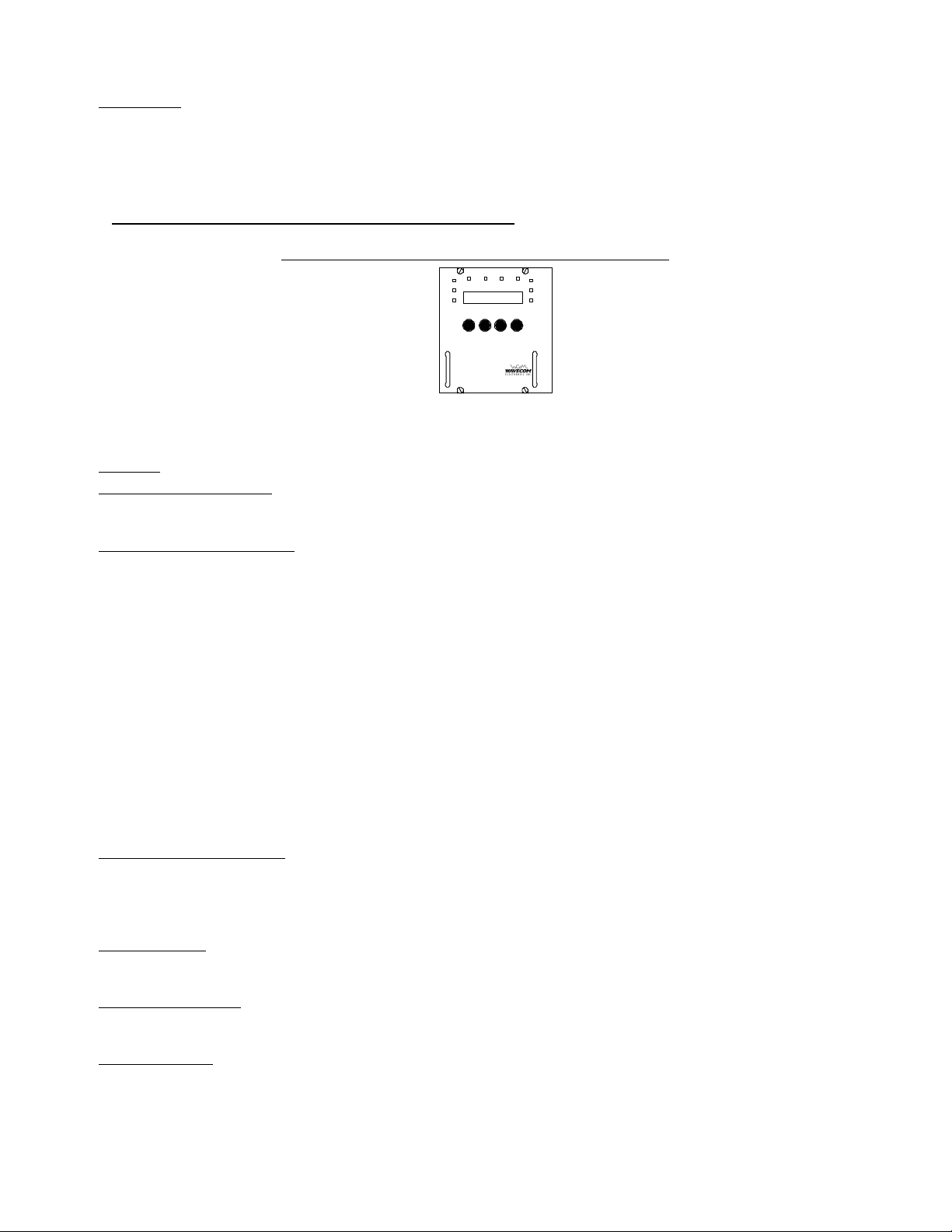
3.1.1 MA4040D
SELECT
MODE MODULE
SELECT
24V
AUX
5V
10V
DD IAGRAM IAGRAM 3.13.1BB : F: FRONT RONT PP ANEL ANEL - MA4040D U- MA4040D UPCONVERTER PCONVERTER MM ODULEODULE
POWER
RF ENABLED
MODULE
SELECT
ALARM
WaveCom
MA4040D
POWER ON LED
When the green POWER ON indicator is illuminated, the module has been correctly installed and powered on.
RF ENABLED LED
When the green RF ENABLED indicator is illuminated, the internal output circuitry is enabled to provide an RF
output. The RF ENABLED indicator does not necessarily indicate the presence of an output, it only reflects that the
module is capable of an RF output if an IF input is applied and the levels configured.
MODULE SELECT LED
When the green MODULE SELECT indicator is illuminated, it indicates that the corresponding module has been
selected from the front panel or via the remote control interface.
WaveCom Electronics Inc
MA4040D Manual; MAN1L0901 REV 13(0104)
Approved: D.P.
13
ALARM LED
The red MA4040D ALARM indicator has two modes. A flashing Alarm LED indicates a non-critical alarm condition
(i.e. soft alarm). A constant Alarm LED indicates a critical alarm condition (i.e. hard alarm). Detailed alarm
information is available by selecting the corresponding module from the front panel and observing the status and
error codes on the LCD display.
3.1.2 MA4011D (or MA4012D) Power/Control Module
DD IAGRAM IAGRAM 3.13.1C C :: FF RONT RONT PP ANEL ANEL - MA4011D P- MA4011D POWER OWER SS UPPLYUPPLY
24V
POWERALARMMODULE
5V
10V
STATUS STATUS
24V
AUX
SELECT
5V
10V
DOWN UP MODEMODULE
SYSTEM 4000
POWER SUPPLY
WaveCom MA4011D
SELECT
* The MA4011D and the MA4012D power supplies have the same front panel functions and
displays. Diagram 3.1C represents both the MA4011D and the MA4012D.
DISPLAY
The first line on the display is the Mode Information Line. It shows the settings for the currently selected mode. The
possible operating modes depend upon the currently selected module. (See Section 3.2, Front Panel Operating
Modes (pp 14, 15) for a detailed description of the available modes).
The second line on the display is the Status Information Line. The Status Line is divided as follows:
The two leftmost characters are “mX” where X is replaced by the currently selected module address. Looking at
the front of the MA4000D system, the module addresses are assigned starting with module A in the leftmost slot in
the chassis and module K in the Power Supply. The modules in between are lettered B through J. (As shown in
Diagram 3.1A (p 12)). Modules can be installed in any open slot, and not all slots need to be filled.
The next two characters are “sXX” where “XX” indicate the status code for the currently selected module. Refer to
Section 5.0, Status Codes (pp 23, 24) for a list of current status codes.
The next two characters are “eXX” where “XX” indicates the error code for the currently selected module. (This
code is only displayed when it is non-zero). Refer to Section 6.0, Error Codes (pp 25, 26) for the list of current
error codes.
The final three or four characters of the second line can display the following information:
•
When under Remote Control and local control is disabled, it will read “RMT”
•
When under Local Control and a MA4040x card is selected, it will display the current firmware revision of the MA4040x
card (ex “r118”)
•
When under Local Control and a module other than a MA4040x is selected, this area will be blank
MODULE SELECT BUTTON
The MODULE SELECT button allows the user to select the module to display and/or control (the MODULE
SELECT LED will be lit on the selected module, and the LCD display will indicate the module address in the status
line).
MODE BUTTON
The MODE button allows the user to cycle through each of the various modes for the selected module.
UP/DOWN BUTTONS
The UP/DOWN arrow buttons adjust the settings for the currently selected mode.
POWER ON LED
When the green POWER ON indicator is illuminated, the module has been correctly installed and powered on.
WaveCom Electronics Inc
MA4040D Manual; MAN1L0901 REV 13(0104)
Approved: D.P.
14

ALARM LED
A constant Alarm LED on the MA4011D indicates a critical alarm condition. Detailed alarm information is available
by selecting the module from the front panel and observing the status and error codes on the LCD display.
MODULE SELECT LED
When the green MODULE SELECT indicator is illuminated, it indicates that the corresponding module has been
selected from the front panel or via the remote control interface.
AUX LED
This LED is reserved for future use.
3.2 Front Panel Operating Modes
3.2.1 MA4040D Upconverter Modes
FREQUENCY
When this mode is selected, the display will read : Frq XXX.XXXX MHz
The displayed frequency is the current configured Output Frequency. To adjust the output frequency, use the
UP/DOWN arrow buttons. Single stepping will allow 12.5 kHz adjustment, while holding the buttons depressed will
change the frequency more quickly.
* The displayed frequency represents the center of the band.
* During frequency change, the output is muted and the RF ENABLED indicator is turned off for
5 seconds to avoid undesirable interference.
AUTO IF
When this mode is selected, the display will read: IF AGC Enabled
or
IF AGC Disabled
Pressing the UP/DOWN buttons will toggle the display between Enabled and Disabled. When enabled, the
MA4040D will automatically optimize the IF level and ensure it is within a pre-set threshold range (default ±0.5 dB).
When disabled, the IF level can be manually adjusted as described in the next section.
* The Auto IF mode should only be used for continuous IF inputs (non-bursty).
* The Auto IF mode should be used for proper operation in redundant mode.
* If the IF level is not within ±4.0 dBmV of the optimum level during Auto IF mode, the output will
be muted to avoid undesirable interference, and the Alarm LED will be on.
* At the time of shipping, the AUTO IF is enabled.
* Because the IF AGC has been optimized for digital QAM signals, it is recommended that
AUTO IF is disabled for analog signals.
IF LEVEL ADJUST
When this mode is selected, the display will read: IFPwr ±±XX.X dB
The display indicates the approximate IF power level measured at the internal IF power detector. To adjust the IF
level, use the UP/DOWN arrow buttons. To configure the MA4040D Upconverter for optimum performance, the IF
level should be adjusted to read approximately 0.0 dB (-0.5 to +0.5). An IF level less than 0 dB will degrade noise
performance and a level above 0 dB will promote intermodulation products.
* The IF level can only be adjusted if the Auto IF mode is disabled.
WaveCom Electronics Inc
MA4040D Manual; MAN1L0901 REV 13(0104)
Approved: D.P.
15
 Loading...