


USER MANUAL
5760 Series
25/50/100 Watt Digital
Amplifier
AXCERA, LLC
103 FREEDOM DRIVE P.O. BOX 525 LAWRENCE, PA 15055-0525 USA
(724) 873-8100 • FAX (724) 873-8105
www.axcera.com • info@axcera.com
The 5760 has no front panel adjustments, however there are several adjustments and test points on the Power
Detector/Control board. The board is mounted in the upper right corner with abbreviations engraved on the
mounting plate. The left to right arrangement is:
Test point for setting Reflected power
Test Point for setting Peak Forward Power
Test Point for setting Forward Envelope power
RZ Reflected Power Zero adjust
RL Reflected Power Level adjust
GT Gate Timing (for encoded signals)
FL Forward Power Level adjust
FZ Forward Power Zero adjust
GL Gate Level adjust (for encoded signals)
Test Point for Ground
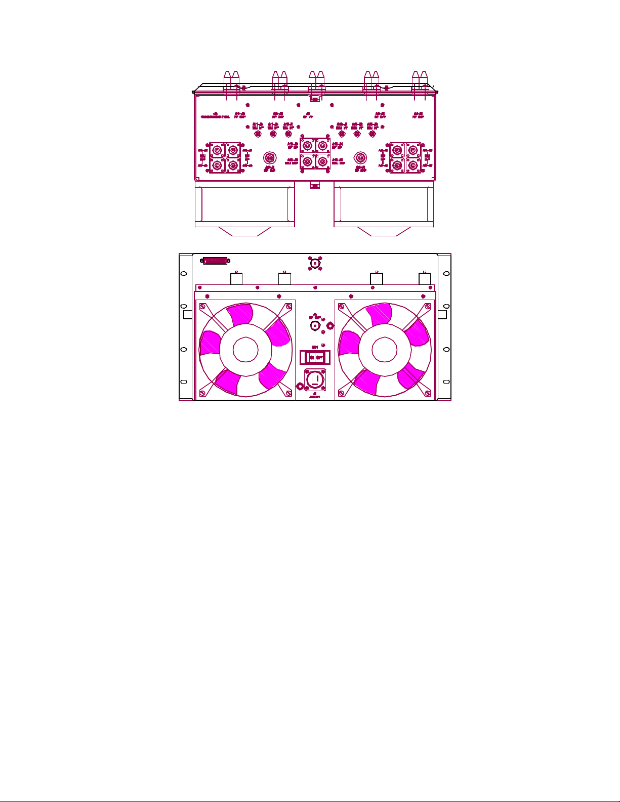
J1 A.C. Input
J2 RF Input “N” connector
J3 Remote/control “D” connector
J4 RF Output “N” connector
J3 Pinouts are:
3 Ground
4 Remote Forward Power
6 Remote Reflected Power
8 Operate Command Output
9 Amplifier Interlock
10 Amplifier Interlock Return
15 AGC Outer Loop
16 Remote Overtemp.
18 Amplifier Fault
19 Ground
20 Power Supply Fault

Internal LED Indicators 5760
Enable green
DC OK green
Bias green
MOD OK green
RF O/P green

5765
DIGITAL AMPLIFIER
TABLE OF CONTENTS
I. INTRODUCTION:
II. SYSTEM 5765: ................................................................................1586-1003
A. SYSTEM DESCRIPTION
B. SPECIFICATIONS
III. AMPLIFIER:
A. DRAWINGS:
2. INTERCONNECT .........................................................1586-8003
B. AMPLIFIER SUBASSEMBLIES
VI. MAINTENANCE:
A.
This section contains information on troubleshooting, problem analysis and
repair procedures for the 5765.

5765
25 WATT DIGITAL AMPLIFIER
SYSTEM DESCRIPTION
The 5765 is a digital amplifier capable of operating at a nominal output power of 50 watts
average. The 5765 is comprised of a 25W Power Amplifier Subassembly, a Power Factor
Corrected (PFC) Front End Module, Peak Detector/Control Board, and a directional coupler.
Combining the latest in GaAs FET amplifier technology and Feed Forward distortion
cancellation, the 5765 delivers an output power of 25 watts (average).
The unit's circuitry is enclosed in a tray assembly designed for mounting in a standard 19"
equipment rack. The unit comes complete with slide rail mounting hardware to allow the tray
to move in and out of the rack for ease of service. The outside dimensions of the tray
assembly are 19" x 30" x 10.25" (WxDxH).
The 5765 is factory calibrated for a front panel LCD display external power meter reading of
100% on the driver transmitter, which represents the rated output power of the unit (unless
otherwise specified).

SPECIFICATIONS
Technical Specifications
Type of Emissions .................................................................... 6M00D7W
Frequency Range .....2150 to 2162 and 2500 to 2686 MHz (any 6 MHz channel)
Output Power Rating...................................................... 25 watts average
DC voltage and total current of final amplifier stage .. 10 volts DC at 32.5 amps
(Class A - Not RF power dependent)
Performance Specifications
Operating Frequency Range ................... 2150 to 2162 and 2500 to 2686 MHz
RF output - Nominal:
Power .........12.5 to 25 watts average (adjustable in driver transmitter)
Impedance ......................................................................50 ohms
Connector........................................................................ Type N
Input (64 QAM Digital Signal) ......................................................... Type N
Out-of-Band Power .......................................-38 dB max (at channel edge)
-60 dB max (3.0 MHz above channel edge and 3.0 MHz below channel
edge)
Electrical Requirements
Power Line Voltage ............................................. 208/240 VAC, 50 or 60 Hz
Power Consumption ................................................................ 1243 watts
Environmental
Maximum Altitude..................................................... 12,000 feet (3,660m)
Ambient Temperature ............................................................ 0° to +50°C
Mechanical
Dimensions: (WxDxH) ............... 19" x 30"x 10.25" (48.3cm x 76.2cm x 26.0cm)
Weight: ...................................................................... 85 lbs. (38.6 kgs)

5765
25 WATT POWER AMPLIFIER
DRAWING LIST
Power Detector/Control Board.......................................................................1586-1118
Schematic..............................................................................................1586-3118
25 Watt Power Amplifier Assembly .................................................................1586-1117
Interconnect ..........................................................................................1586-8117
The 25 Watt Amplifier Assembly consist of the following boards/modules:
25 Watt Amplifier Module .............................................................................1585-1266
Schematic..............................................................................................1585-3266
Amplifier Daughter Board ..............................................................................1512-1110
Schematic..............................................................................................1512-3110
8 Section Bias Protection Board ....................................................................1586-1109
Schematic..............................................................................................1585-3109
DC to DC Converter Board
Schematic............................................................................................... DT380-11
The Power Factor Corrected Front End Module consist of the following power supplies:
PFC 200W Supply ...........................................................................(VS3) 73-450-0001
40W Switching Supply....................................................................................... LPS23
80W Switching Supply....................................................................................... LPS63

5765
25 WATT DIGITAL AMPLIFIER
SYSTEM DESCRIPTION
The 5765 is a digital amplifier capable of operating at a nominal output power of 50 watts
average. The 5765 is comprised of a 25W Power Amplifier Subassembly, a Power Factor
Corrected (PFC) Front End Module, Peak Detector/Control Board, and a directional coupler.
Combining the latest in GaAs FET amplifier technology and Feed Forward distortion
cancellation, the 5765 delivers an output power of 25 watts (average).
The unit's circuitry is enclosed in a tray assembly designed for mounting in a standard 19"
equipment rack. The unit comes complete with slide rail mounting hardware to allow the tray
to move in and out of the rack for ease of service. The outside dimensions of the tray
assembly are 19" x 30" x 10.25" (WxDxH).
The 5765 is factory calibrated for a front panel LCD display external power meter reading of
100% on the driver transmitter, which represents the rated output power of the unit (unless
otherwise specified).

SPECIFICATIONS
Technical Specifications
Type of Emissions .................................................................... 6M00D7W
Frequency Range .....2150 to 2162 and 2500 to 2686 MHz (any 6 MHz channel)
Output Power Rating...................................................... 25 watts average
DC voltage and total current of final amplifier stage .. 10 volts DC at 32.5 amps
(Class A - Not RF power dependent)
Performance Specifications
Operating Frequency Range ................... 2150 to 2162 and 2500 to 2686 MHz
RF output - Nominal:
Power .........12.5 to 25 watts average (adjustable in driver transmitter)
Impedance ......................................................................50 ohms
Connector........................................................................ Type N
Input (64 QAM Digital Signal) ......................................................... Type N
Out-of-Band Power .......................................-38 dB max (at channel edge)
-60 dB max (3.0 MHz above channel edge and 3.0 MHz below channel
edge)
Electrical Requirements
Power Line Voltage ............................................. 208/240 VAC, 50 or 60 Hz
Power Consumption ................................................................ 1243 watts
Environmental
Maximum Altitude..................................................... 12,000 feet (3,660m)
Ambient Temperature ............................................................ 0° to +50°C
Mechanical
Dimensions: (WxDxH) ............... 19" x 30"x 10.25" (48.3cm x 76.2cm x 26.0cm)
Weight: ...................................................................... 85 lbs. (38.6 kgs)

5765
25 WATT POWER AMPLIFIER
DRAWING LIST
Power Detector/Control Board.......................................................................1586-1118
Schematic..............................................................................................1586-3118
25 Watt Power Amplifier Assembly .................................................................1586-1117
Interconnect ..........................................................................................1586-8117
The 25 Watt Amplifier Assembly consist of the following boards/modules:
25 Watt Amplifier Module .............................................................................1585-1266
Schematic..............................................................................................1585-3266
Amplifier Daughter Board ..............................................................................1512-1110
Schematic..............................................................................................1512-3110
8 Section Bias Protection Board ....................................................................1586-1109
Schematic..............................................................................................1585-3109
DC to DC Converter Board
Schematic............................................................................................... DT380-11
The Power Factor Corrected Front End Module consist of the following power supplies:
PFC 200W Supply ...........................................................................(VS3) 73-450-0001
40W Switching Supply....................................................................................... LPS23
80W Switching Supply....................................................................................... LPS63

MAINTENANCE AND TROUBLESHOOTING
Problem Analysis
In most cases, the performance of a GaAsFET transistor is closely tied to the DC operation of the system. Any
degradation in signal quality, gain or power is usually related to a corresponding change in a DC parameter
somewhere in the system. An exception may be a defective RF input or output connection, which can result in poor
performance of the amplifier with all DC parameters appearing normal.
The first step of analysis is therefore to carefully measure all DC parameters and compare these to the numbers
indicated on the schematics, block diagrams, and factory test data sheet. Each GaAsFE T operates with – .5V of bias
on the gate and about +10.2V maximum volts on the drain. The static current of a GaAsFET is determined by
measuring across associated .05 ohm resistor, located on the bias protection board and using Ohm’s Law .
If all DC parameters are normal, an RF intermittency should be suspected. Follow the RF path from input to output
and apply a small physical force on all connectors while observing the output power. If an intermittency is detected, a
simple re-soldering can be attempted.
While following these procedures, it is important to maintain terminations on all amplifier circuits to avoid VSWR
damage. Before a fan fails, it normally begins to exhibit noisy operation. Always check for free fan blade movement
and procure a replacement fan if fan-bearing noise is evident.
Repair Procedures
Repair of this transmitter normally involves module level replacement. ITS Corporation maintains an adequate stock
of replacement modules. If you have determined that a particular subassembly is defective and that it cannot be
easily repaired at your facility, please contact the ITS Customer Services Department. An effort will be made to
provide a module on an exchange basis. It is often possible to ship replacement modules counter-to-counter or oneday UPS/Federal Express to expedite delivery.
On some occasions it is necessary to perform component level repairs. In many cases failures can be a result of poor
connections somewhere in the system. Poor connections can generally be repaired with a suitable, small, grounded
soldering iron. A spare parts kit of standard components is available for this booster. Please contact the ITS
Marketing Department for the price and availability of the spare parts kit. Individual components can also be ordered
from the Customer Services or Marketing departments of ITS. The fuses are standard and generally available at local
parts distributors. The parts list provides complete manufacturer's information and part number for all standard
electrical components. These components can often be obtained from local distributors. An effort has been made to
select standard (off-the-shelf) components whenever possible in the product design. Replacement of the GaAsFET
transistors in the field is not recommended unless performed by an experienced technician. It is important to realize
that each GaAs FET operates at a specific bias voltage that must be preset before the main power supply is switched
on. Failure to provide the proper bias voltage will result in rapid GaAsFET destruction. Please refer to the ITS
Warranty and Material Return Authorization procedures for additional information concerning repair parts.
Periodic Procedures
This transmitter is designed with components that require no periodic maintenance except for cleaning and record
keeping.

The amount of cleaning necessary depends greatly on the conditions in the translator room. While the electronics
have been designed to function well even if covered with dust, heavy buildups of dirt and insects will impede the
effectiveness of the cooling and lead to shutdown or premature failure.
When it is apparent that the front panel is becoming dust covered, the top cover should be opened and the
accumulated foreign material removed. A small, soft brush used in conjunction with a plastic wand-like attachment on
a small vacuum cleaner is an excellent way to remove dirt. Alcohol and other cleaning agents should not be used
unless you are certain that the solvents will not damage components or markings. Water based cleaners can be used
if only a small amount of moisture is used. The fans or heat sinks should be carefully cleaned.
Occasionally check that all RF connections are secure, but be careful not to over -tighten.
Data should be recorded for all meter readings on a regular basis. It is suggested that data be recorded once each
month and that it be retained in a rugged folder or envelope for the life of the equipme nt. A sample format of a log
sheet is included at the end of this section. Photocopies of this sheet may be used for if desired.
 Loading...