

Axcera 79XITS-7025, 79XITS-7040, 79XITS-7026 User Manual
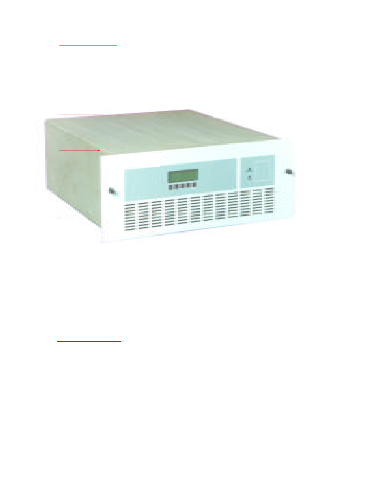
Table of Contents
INTRODUCTION
SYSTEM
Unpacking/Installation ............................................................................
System Description ................................................................................
Specifications .......................................................................................
System Block Diagram and Interconnect .................................................
Front Panel ...........................................................................................
Rear Panel ............................................................................................
OPERATION
Initial Turn On .......................................................................................
Status Screens .....................................................................................
Setup Screens ......................................................................................
MODULES
Module Replacement
How to replace a module.........................................................................
Backplane Board
Description ...........................................................................................
Modulator Module (optional)
Description ...........................................................................................
Power Supply Module
Description ...........................................................................................
Power Amplifier Module
Description ...........................................................................................
LO/Upconverter Module
Description ...........................................................................................
If Processor Module
Description ..........................................................................................
Control And Monitoring Module
Description ...........................................................................................
LCD Display
Description ...........................................................................................
INDEX/APPENDIX
Typical Transmitter Site ..........................................................................
Troubleshooting .....................................................................................
Material Return Procedure/Exchanges........................................................
Telephone Technical Support ...................................................................
First Aid Procedures ...............................................................................
Proper Packing of Materials......................................................................
Warranty ..............................................................................................
Abbreviations and Acronyms ....................................................................
June 1, 2004

INTRODUCTION
The 5720 series product line is designed with the user in mind.
With the implementation of modular component technology, it is
no longer necessary to perform component level repairs at the
site. By simply replacing an entire module the unit is quickly ready
to return to normal operation.
The unique hinged front panel eliminates the need to remove the
unit from the cabinet for routine inspection and maintenance.
5720 series products can also be upgraded just by making a few
simple adjustments and changing specific modules.
With additional features such as ability to connect to external amplifiers, change output power, and an optional spectral shaping filter, 5720 series products are versatile as well as cost effective.
This manual covers all power levels of the 5720 including the 5721,
5722, 5723, and 5724.
3

Unpacking
Axcera certifies that upon leaving our facility all equipment
was undamaged and in proper working order. It is imperative that all packages be inspected immediately when received to verify that no damage occurred in transit to the
site.
SYSTEM
· Inspect all packages for exterior damage and
make note of any dents, broken seals, or
other indications of improper handling.
· Carefully open each package and inspect the
contents for damage. Verify that all materials are enclosed as listed on the packing slip.
Report any shortages to Axcera.
· In the event any in transit damage is discovered report it to the carrier. Axcera is not
responsible for damage done by the carrier.
· If the equipment is not going to be installed
immediately, return all items to their original
packaging for safe storage.
Installation
All 5720 series products are designed for simple installation
with comprehensive instructions. Expensive test equipment
is not required to keep a system operational, installation,
and set up. Prior to installing the product review the checklist that follows.
· Save all packing material for future use. If
equipment is ever removed from the site, the
original packaging will ensure the safe transport of it. Keep at least one copy of all documentation including this manual at the site in
a safe place.
4

· Is the building structure where the equipment is
to be placed properly prepared ? Listed below are
systems and specifications that need to be operational prior to installation of transmission equipment.
Heating and Air Conditioning
Electrical Systems
Building Structure
Antenna
Satellite Dish
Transmission Line
· Have all the systems listed above been tested and/
or inspected ?
· Is the space provided for equipment racks sufficient ? Will an additional devices that extend out
above or to the side of the unit have sufficient
clearance space ? Refer to the system custom racking plan for detailed specifications.
Input Connections for Analog Operation:
Connect the Baseband Video Signal Input to J2, a 75 ohm BNC
connector located on the rear of the tray.
Connect either the Baseband Balanced Mono Audio Signal Input
to J11, a 600 ohm 3 terminal block connector located on the
rear of the tray, or the Unbalanced Composite Stereo Audio Signal Input to J3, a 75 ohm BNC connector also located on the rear
of the tray.
Input Connections for Digital Operation:
Connect the Digital IF Signal Input to J14, a 75 ohm BNC connector located on the rear of the tray.
NOTE: For connections using Scientific Atlanta and Pac-Mono
scrambling, refer to that section which follows.
Output Connections for Typical Operation:
Connect RF Output of the tray at J8, a 50 ohm N connector,
located on the rear of the tray, to the designated Channel Combiner or Spectral Shaping Filter for your system.
Check that CB1 the AC circuit breaker, located on the rear of the
tray near the AC input Jack, is Off.
Connect the AC power cord the J1 on the rear of the tray and
the plug end to an appropriate AC outlet.
5
System Description
5720 series transmitters are available in various power levels from 2.5 to 100
watts average power or 10 to 230 watts peak analog. Units can be factory set to a
specific channel in the 2076-2700 MHz range. QAM signals up to M=256 as well as
NTSC and PAL modulation can be processed by the unit. A center frequency of
either 44 MHz or 36 MHz can be set at the factory prior to shipment.
All 5720 series transmitters are compatible with SCADA . Using SCADA allows
operators to monitor and control systems from remote locations.
6

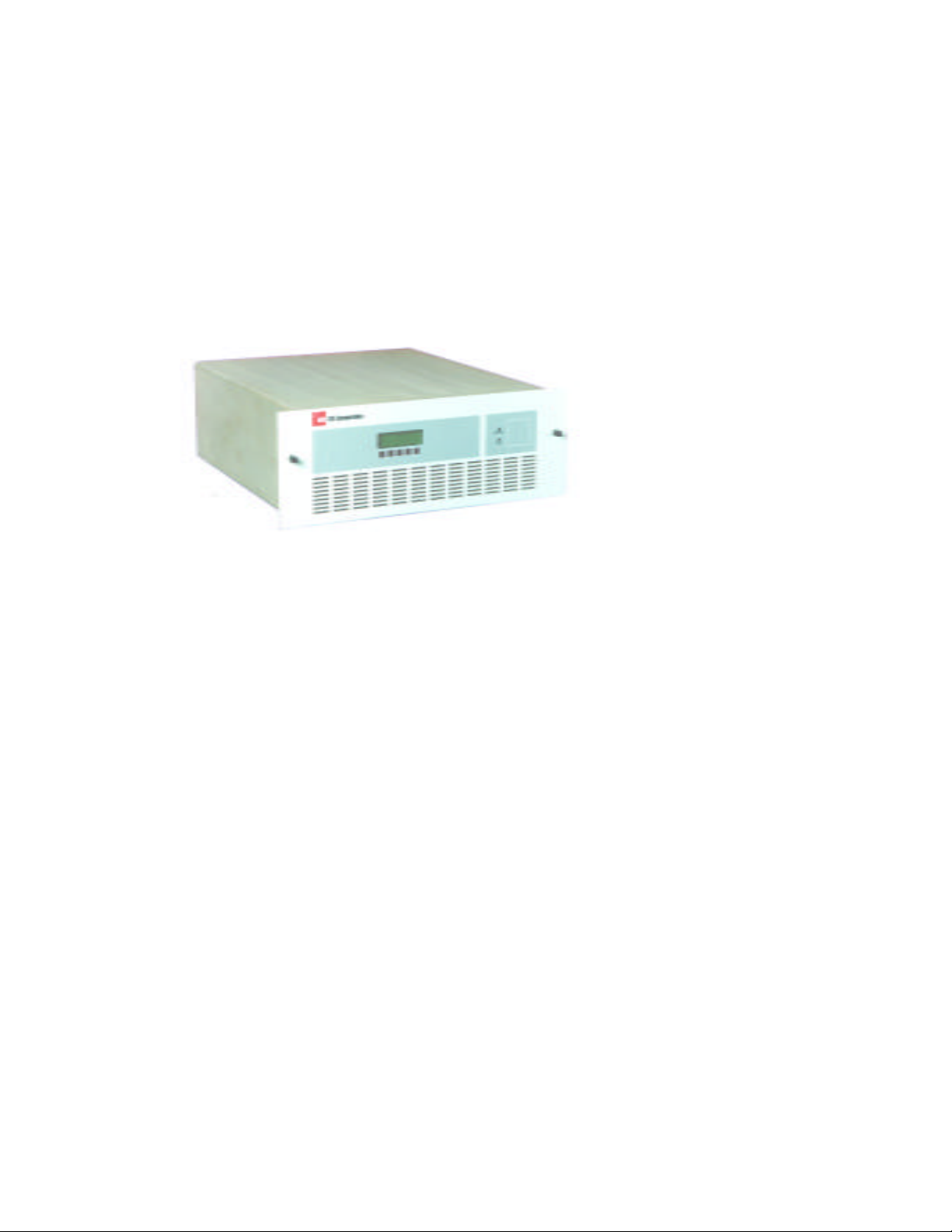
Digital / Analog
MMDS Transmitter
Compatible with digital and analog
modulation including 256 QAM, NTSC, and
PAL
Broad power range of 2.5 to 100 watts
average digital power and 10 to 280 watts
peak sync analog power
Modular design simplifies installation, field
service, and upgrades
Hot-replaceable modules improve system
availability
Redundant design enables system to stay
on the air even if an amplifier module fails
Broadband amplifier design simplifies repairs
and minimizes inventory
High efficiency GaAsFETs reduce operating
expenses and save space
User friendly diagnostics with English,
Portuguese, and Spanish text
Adjacent and non-adjacent channel
combining systems available
SNMP Network Management System
Automatic and manual backup systems
available
5720
The new 5720 series transmitters are the
result of a global design strategy. All aspects
of the product design, from frequency range
to modularity, reflect a long term commitment
to our global partners. These transmitters
provide a platform which allows for simplified
installation, field service and system
upgrades. Axcera has taken significant steps
to reduce system operating costs and size,
while providing a solution that works for
either analog or digital transmission.
Compatible with Digital and Analog Modulation
The 5720 series transmitters are compatible
with digital and analog modulation including
256 QAM, NTSC, and PAL. An internal NTSC/
PAL modulator is available to save rack
space.
5720 Series Provides Broad Power Range
Operators can select from 2.5 to 100 watts
of average power, or 10 to 280 watts of peak
sync analog power. Transmitters can be set
for any channel in the 2076-2700 MHz
frequency range.
Modular, Reliable Design
Modular design simplifies installation, field
service, and upgrades. Modulator, IF, LO/
upconverter, amplifier, power supply, and
transmitter control modules can be replaced
in seconds. Each slide into a backplane with
plug-in connectors. Surface mount technology
improves system MTBF.
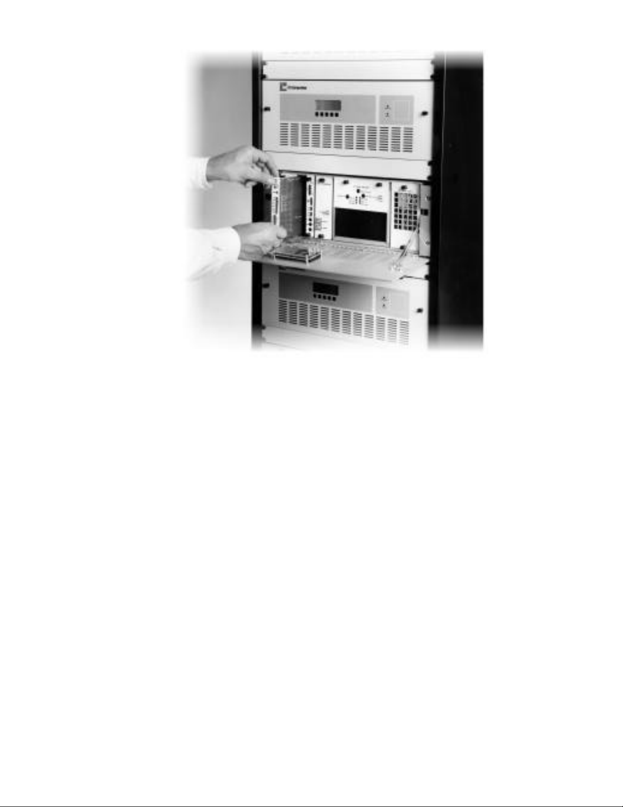
Modular design
simplifies
installation,
field service,
and system
upgrades.
High Efficiency, Broadband Amplifiers
Axcera has selected the newest, most efficient
GaAsFETs for the 5720 series. Redundant
amplifier modules enable the system to stay on
the air in the event of a failure. Amplifier
modules are hot-replaceable so they can be
removed and installed while the system is
operating. Amplifiers are tuned broadband to
simplify repair and reduce spares inventory.
Feedforward and advanced equalization
techniques are employed to meet
the FCC spectrum mask for out-of-band
performance specifications while minimizing power
consumption.
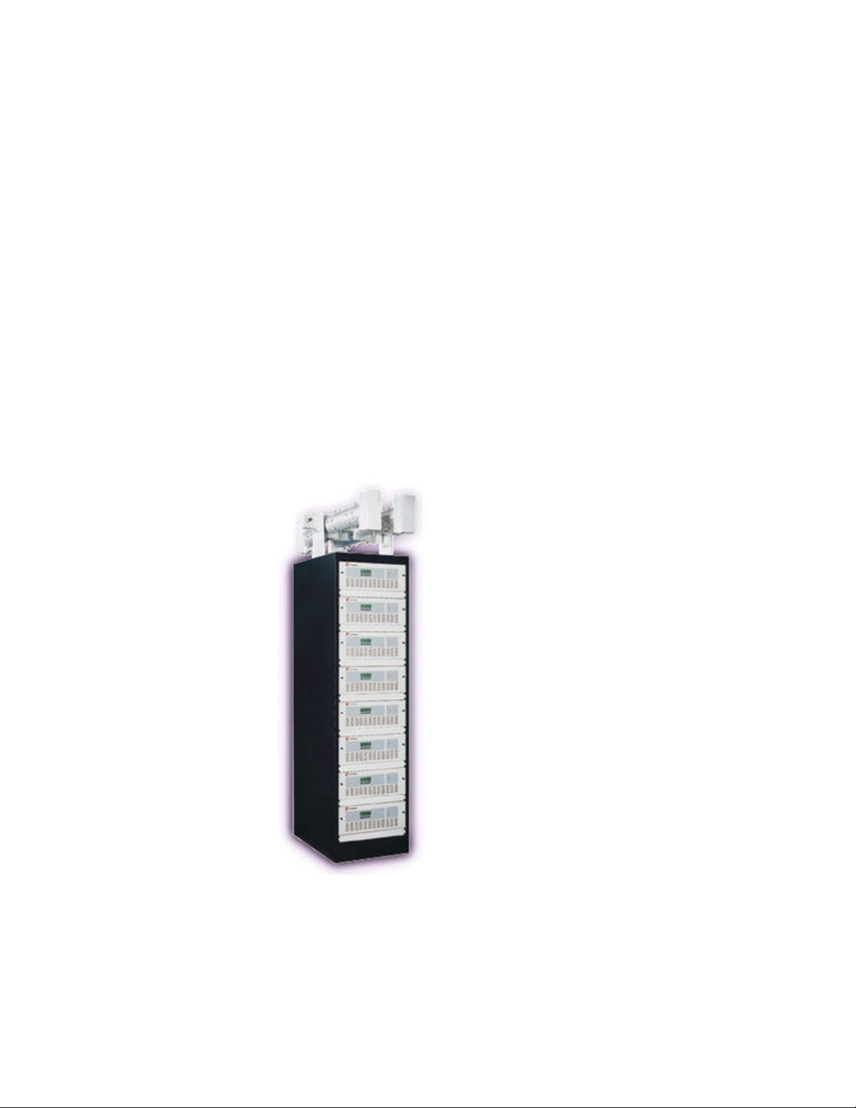
Compact Size
A complete 31 channel system for 50W peak
operation fits into just four racks. Even the new
8770 Filterplexer combiner can be configured for
eight channels per rack. The 8770 Filterplexer is
available for both adjacent and non-adjacent,
analog or digital applications. Adjacent combining
reduces the system purchase price because only
one antenna and waveguide run are required.
Anytime, Anywhere Communication and Backup
With the SCADA system operators have real time
remote and local control of the transmitter
system and site. Graphic user interfaces simplify
integration with Windows or UNIX based SNMP
network management systems. Axcera ’s
automatic backup system permits a scaleable
number of channels to be backed up per agile
transmitter.
Turnkey Solutions and 24-Hour Support
At Axcera our transmitters, amplifiers, and
channel combiners are manufactured and tested
as a system to achieve the ultimate in
performance and value. Our system integration
group can document, install, and commission
your entire digital MMDS transmitter system.
Axcera field engineers are available to oversee
analog to digital system conversions and provide
on-site training. We offer a comprehensive range
of support services that are designed to keep
your transmitter system producing revenue year
after year.

5720 Series
Specifications
Subject to change without notice
RF Performance 5721 5722 5723 5724 5725 5726 5727
RF Output Power (PEP Watts) 20 40 50 70 120 220 400
RF Output Power Digital (Avg. Watts) 2.5 5 10 15 25 50 100
RF Output Power Analog 10 20 30 50 100 160 280
(Pk Sync Watts with -15dB Aural)
RF Output Frequency .............................. Any 6, 7, or 8 MHz channel, 2076-2700 MHz
RF Output Impedance ............................. 50 Ohms
Frequency Translation Stability2................ ± 500 Hz standard (Precise ± 1 Hz optional)
Signal to Noise Ratio (6 MHz Bandwidth) ... 52 dB
Discrete Inband Spurious and Harmonic Products -60 dB relative to average digital power or to analog carrier
Out of Band Spurious Products3................ Per FCC digital spectral mask; per FCC or CCIR system analog
Digital Performance
Phase Noise4 (1 Hz Bandwidth 10 kHz from Carrier) £-110 dBc (single sideband measurement)
Frequency Response .............................. ± 0.25 dB
Group Delay .......................................... 40 nsec peak-peak (Measured with 1 MHz delay aperture)
Gain Linearity (AM-AM5) ........................... 0.2 dB /dB
Phase Linearity (AM-PM5)......................... 1°/dB
IF Input Frequency ................................. 41-47 MHz or 32-40 MHz
IF Input Impedance ................................ 75 or 50 Ohms (specify)
IF Input Level ........................................ +20 to +40 dBmV (-28 to -8 dBm) average
Analog Visual Performance
Frequency Response .............................. ± 1.0 dB
Differential Gain ..................................... 5%
Differential Phase ................................... ± 3°
ICPM .................................................... ± 3°
Envelope Delay ...................................... Per FCC or CCIR system
Video Input Impedance ........................... 75 Ohms
Video Input Level ................................... 1 V p-p
Emission Designator ............................... 5M75C3F or per CCIR
Analog Aural Performance
Output Power ........................................ -15 dB relative to visual power
Frequency Deviation Capability ................ Up to ±75 kHz
Harmonic Distortion ................................ 0.5%
FM Noise ............................................... -55 dB FCC TYPE ACCEPTED
Frequency Response .............................. ± 1 dB 50 Hz-15 kHz Baseband Input
Pre-emphasis (Baseband Input) ............... 50 or 75 msec (defeatable)
Audio Input Impedance ........................... 600 Ohms balanced Baseband Input
Audio Input Level ................................... 0 to 10 dBm Baseband Input
Emission Designator ............................... 250KF3E or per CCIR
1. These devices have not been approved by the Federal Communications Commission. These devices are not, and
may not be offered for sale or sold in the United States until the approval of the FCC has been obtained.
2. When interfaced with 5060 10 MHz system reference or GPS precise reference.
3. Measured at output of the Channel Combiner or optional spectral shaping filter.
4. Measured with optional LPN oscillator.
5. Specified at 6dB above digital average power.
6. Measured with optional internal analog modulator.
6
6
± 1 dB 50 Hz-100 kHz Composite Input
75 Ohms unbalanced Composite Input
1V p-p Composite Input
 Loading...