

Page 1
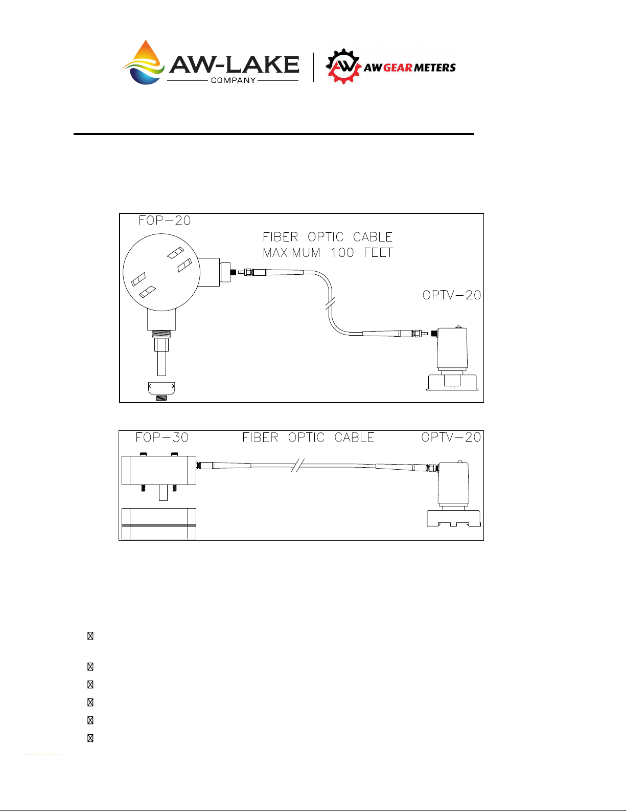
FOP-20 & FOP-30 Fiber Optic Pickup Systems
-
X
-
X
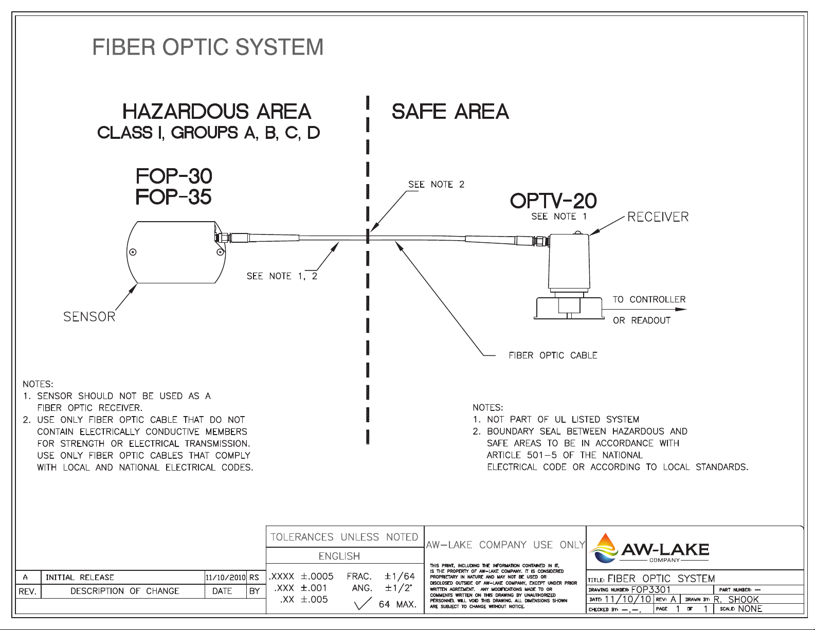
The fiber optic pickup system consists of a FOP 20 or FOP-30 Reluctance Pickup with a Fiber Optic
Transmitter, Fiber Optic Cable and OPTV-20 Fiber Optic Receiver. The FOP-20 is in an Explosion
Proof Housing for use with HPM, JVM, or JVS series flow meters. The FOP-30 is in an intrinsically
safe housing for use with HPM-SLG or JVS-SLG series.
The fiber optic cable is sold in standard length of 30, 45, 60 and 100 feet.
JVS-XXSLG, JVS
HPM-XXSLG, HPM
FOP-20 and FOP-30 Fiber Optic Transmitters
The FOP-20 and FOP-30 fiber optic pickups are designed with the following criteria:
MAXIMUM 100 FEET
XSLGF
XSLGF
To transmit a safe fiber optic signal. This allows the incorporation of flow meters into fully
charged electrostatic paint systems (35 - 120 Kilo Volts.)
User friendly in respect to initial hookup and maintenance.
Swivel connector to flow meter for easy installation/removal. (FOP-20 only)
Single, sealed, extra long life battery and electronic module.
Simple industrial technology that is easy for maintenance personnel to understand.
CMOS technology for long battery life.
N
2440 W. Corporate Preserve Dr. #600, Oak Creek, WI 53154 | www.aw-lake.com | Rev. 07/2017
Page 2
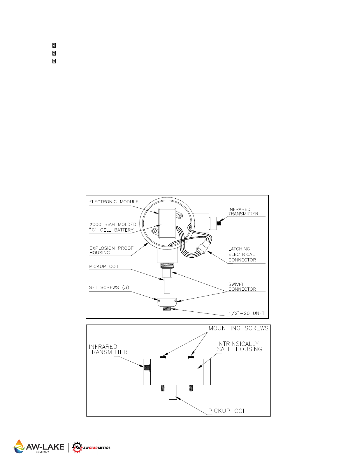
The FOP-20 and FOP-30 consist of the following stages:
Pickup coil
Battery/electronic Module
Infrared transmitter
The pickup coil is the sensing device. The coil is a low ohm, low inductance device embedded in a
stainless steel housing. Embedded in the pickup is a small magnet which will generate pulses to a
coil when the magnetic field in front of the pickup changes. The infrared wave length from the
transmitter is approximately 820 nm and the pulse lasts no longer than 30 μs. By producing this
very short pulse, the life of the internal DC power source can be greatly enhanced.
The power source is a heavy duty 7000 mAH Lithium “C” cell battery. By utilizing CMOS technology
in the FOP amplifier/transmitter, the quiescent current is below 10μA and
approximately 60μA when the gears are turning at 100Hz. Due
battery, a life expectancy of the battery/electronic module is between 5 and 10 years depending
upon the flow rates and time of use. When the battery is installed by AW Gear Meters, a label with
the installation date is taped to the battery. Do NOT remove this label! As preventive maintenance
we recommend keeping a log with the installation dates of all FOP’s in use. These may be
scheduled for replacement at a convenient time after 5 years of operation. This will ensure
uninterrupted service during production operations.
to the very low drainage on the
increases to
FOP-20
FOP-30
2440 W. Corporate Preserve Dr. #600, Oak Creek, WI 53154 | www.aw-lake.com | Rev. 07/2017
l
Page 3
OPTV-20 Fiber Optic Receiver
The fiber optic cable coming from the FOP-20 or FOP-30 terminates in the OPTV-20 receiver. This
receiver consists of an infrared photo-diode, pulse shaper and an amplifier built into a Potter &
Brumfield polycarbonate casing which plugs into an 8 pin Octal style socket.
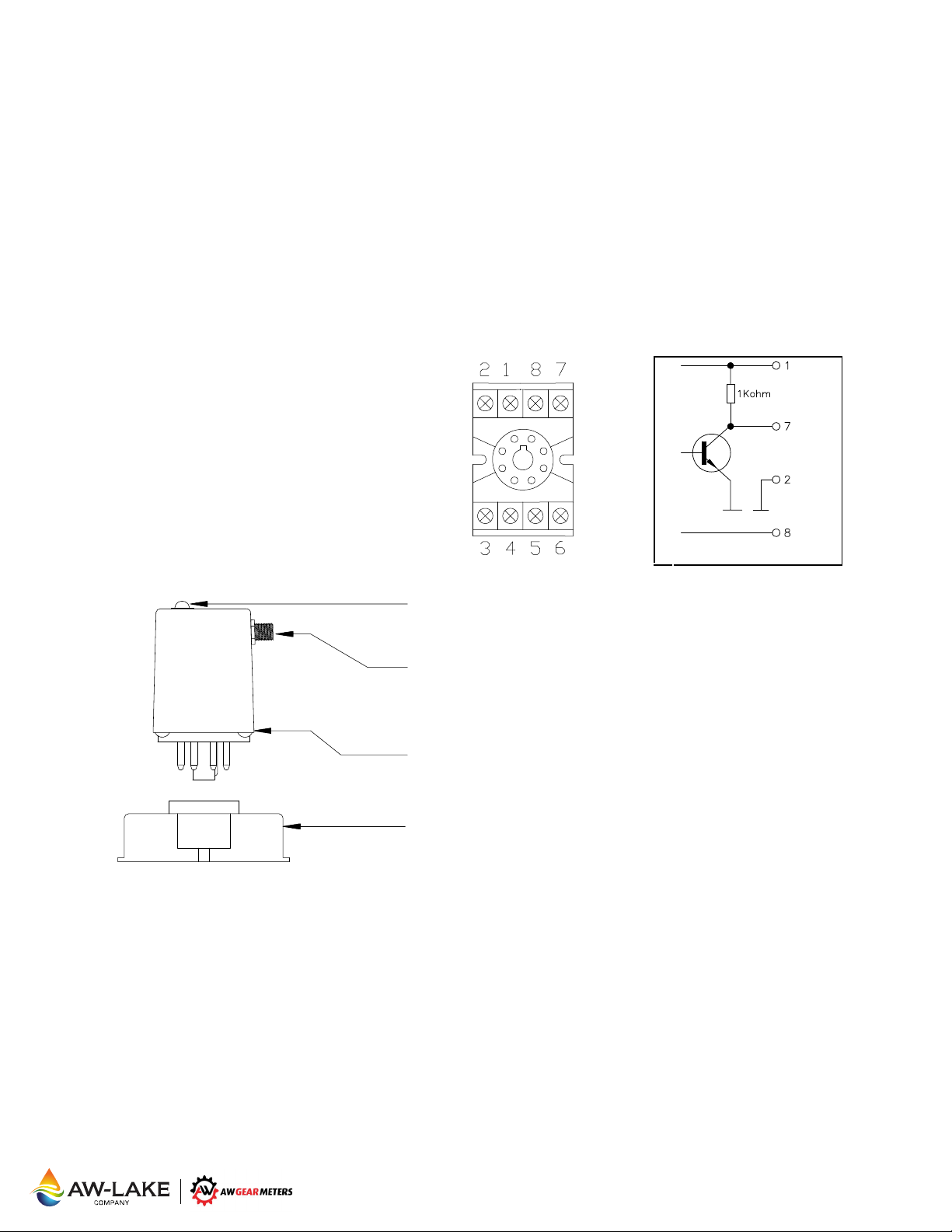
On the top of the module, a red LED is mounted which will blink when a frequency signal is
detected at the fiber optic receiver. It is recommended that the unit be mounted to allow operator
observation of the LED. The output from the OPTV-20 is a square wave frequency which is
proportional to the flow through the flow meter on which the FOP-20 or FOP-30 is mounted.
The maximum frequency should not be over 500 Hz. The output from the OPTV-20 is a
collector amplifier with a 1 KΩ pull-up resistor.
NPN open-
OPTV-20 Connections:
1 - +7 to 20 Volt DC Supply
2 - Ground for supply and signal
3 - Not used
4 - Not used
5 - Not used
6 - Not used
7 - Frequency Signal Output
8 - Fiber Optic Receiver Housing ground
RED LED - Blinks when a pulse is detected
FIBER OPTIC RECEIVER - Cable connection
HOUSING - Potter & Brumfield polycarbonate
BASE - 8 pin Octal style socket
Installation Note: To reduce the chance of noise causing the OPTV-20 to emit false signals, it is
recommended that terminal 8 be connected to either panel (earth) ground or terminal 2 on the
OPTV-20. Panel ground is the preferred choice of connection.
The OPTV-20 has a fixed pulse length of approximately 1 millisecond. As the frequency increases,
the time elapsed between each pulse will decrease resulting in eventual saturation at approximately
1000Hz.
An alternate model OPTV-CM is
OPTV-CM pulse length is approximately 6 milliseconds which saturates at approximately 150Hz.
available for cases where a longer pulse length is required. The
2440 W. Corporate Preserve Dr. #600, Oak Creek, WI 53154 | www.aw-lake.com | Rev. 07/2017
m
Page 4
The Fiber Optic Cable
The fiber optic cable has a dual reinforced PVC outer jacket covering a layer of Kevlar® yarn for
extra strength surrounding a Hytrel
cable is pre-assembled with AMP SMA905 industrial use connector by the manufacturer and is
available in 30, 45, 60 and 100 foot standard lengths. For special length requirements contact
AW-Lake Company. Cables can be joined for extra length or pass through a bulkhead using a
Mating-Sleeve-FOC-Connector AW P.N. CO85040. The end-connectors are installed with
special tools and for this reason NEVER cut the cable.
If the fiber optic cable needs to pass through walls or panels, a hole with a diameter of 3/8" is
needed so the connector can pass through.
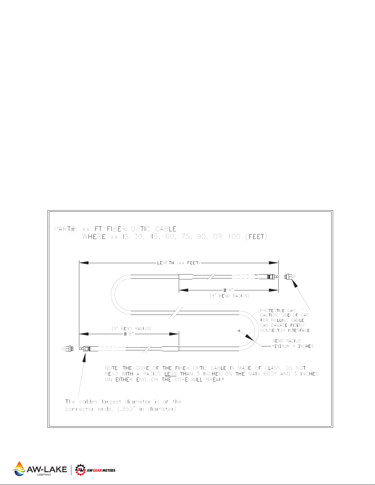
The core of the cable is made of glass, so any sharp bends MUST be avoided or the core could
break. The MINIMUM bend radius for each cable should never be exceeded (see drawing
below).
Always be very careful not to damage the
protective cap MUST be kept on at all times.
FIBER OPTIC CABLE
®
tight buffered optical fiber by Spectran®. The fiber optic
ends of the fiber optic cable. During installation the
2440 W. Corporate Preserve Dr. #600, Oak Creek, WI 53154 | www.aw-lake.com | Rev. 07/2017
n
Page 5

Troubleshooting
If there are any problems during operation or installation, first check all wiring and fiber optic cable
connectors for loose or faulty connections.
1. Wiring Check:
Set up the flow indicator unit in Totalizer mode, so any impulses to the indicator can be registered
as an increased count. Disconnect the wire to terminal 7 on the OPTV-20. Repeatedly touch the
wire to terminal 1 (+15 Volt) on the socket. If the wiring and the flow indicator are OK, there should
be impulses registering on the display.
2. OPTV-20 Check:
The OPTV-20 can be checked by inserting the fiber optic cable from another working system and
see if any impulses are registered at the flow indicator.
3. Fiber Optic Cable Check:
If the OPTV-20 checks out OK
known to be in working order. Connect cable between good FOP and good OPTV-20 and wave a
screwdriver or other ferrous object in front of
good.
4a. FOP-20 Check:
Loosen the 3 set screws on the FOP-20 swivel connector with a 1/16" Hex key wrench and remove
the FOP-20 from the flow meter. With all wires and fiber optic cables connected, move a piece of
ferrous metal rapidly and repeatedly very close to the tip. If all is OK, impulses should be read on
the display on the indicator. The problem then could be that the FOP-20 is not all the way into the
flow meter. The end of the
sure the end of the pickup is seated on the bottom of the hole in the flow meter, and secure the
FOP-20 with the set screws again.
4b. FOP-30 Check:
Remove the FOP-30 pickup sensor from the flow meter body by removing the hex bolts using a 3
mm key wrench. With all wires and fiber optic cables connected, move a piece of ferrous metal in
front of the tip of the pickup sensor. If all is OK, impulses should be read on the display on the
indicator. The problem then could be that the FOP-30 is not all the way into the flow meter. Make
sure the body of the pickup is seated flush against the flo
30 with the hex bolts. The bolts should only be lightly tightened to prevent sensor damage.
5. Erratic Readings in a Charged High Voltage System
If you are experiencing erratic readings when operating in a charged high voltage system it could be
due to a small transient voltage carried on the surface of the fiber optic cable. By
terminal 8 on the OPTV-20 to terminal 2, the metal housing on the fiber optic receiver will be
grounded, and the leakage will be routed to ground. If this does not help, try to connect terminal 8 to
a solid chassis ground by the OPTV-20.
6. Grounding the Flow Meter in a Charged High Voltage System
If using an electrostatic system - if possible, i
base mount of the flow meter body.
If the problem still can not be found, please call AW Gear Meters for technical assistance or return
authorization.
- the fiber optic cable can be checked with an FOP and OPTV-20
FOP pickup nose. If OPTV-20 LED blinks, cable is
pickup must be touching the bottom of the hole in the flow meter. Make
w meter housing before securing the FOP-
connecting
t is recommended to run a grounding wire to the
2440 W. Corporate Preserve Dr. #600, Oak Creek, WI 53154 | www.aw-lake.com | Rev. 07/2017
o
Page 6
2440 W. Corporate Preserve Dr. #600
Oak Creek, WI 53154
Phone: 414.574.4300
Fax: 414.574.4301
 Loading...