


A800MMX
1/10-SCALE TOURING CAR
INSTRUCTION MANUAL
INTRODUCTION
C Awesomatix !
T A800 X as b UAB A x c
T A800 X s q , v
BEFORE YOU START
T
A800M X is
the -q , v v / - b b b v
x b R/C
T b v b , k b
R b b b I v b
q A x @ x I , ,
Y
A800M X
A800M X
b UAB A x xchan b
b b
b
This kit is a radio controlled model racing product and could cause harm and personal injury.
The
A800M X
is designed for use on r/c car race tracks. It should not be used in general public areas.
Awesomatix accept no responsibility for any injuries caused by making or using this kit.
velopment the exact specifications of the kit may vary.
Awesomatix do reserve all rights to change any specifications without prior notice. All rights reserved.
ASSEMBLY NOTES
b - k ve q z b - T
b
A800M X
v - z small
k y correct iz / You can find the useful tips and pictures of A800M X
assembling on the Internet site:
http://site.petitrc.com/reglages/awesomatix/SetupSheetsAwesomatixA800.html
GENERAL PRECAUTIONS
• Many of the items in this kit are small enough to be accidentally swallowed and are therefore potential choking hazards, making them potentially fatal.
Please ensure that when assembling the kit you do so out of the reach of small/young children.
• Take care when building, as some parts may have sharp edges.
• Please read this manual carefully to understand which ancillary items (tools, electrics, electronics etc) are used with this kit.
• Never touch rotating parts of the car as this may cause injury.
• Do not run your car in poor light or if it goes out of sight. Any impairment to your vision may result in damage to your car or, worse, injury to others
• As a radio controlled device, your car is subject to radio interference from things beyond your control. Any such interference may cause a loss of
Awesomatix accept no responsibility for the operation of any such ancillary items.
Exercise care when using tools and sharp instruments.•
Follow the operating instructions for the radio equipment at all times.•
Keep the wheels of the model off the ground when checking the operation of the radio equipment.•
To prevent any serious personal injury and/or damage to property, be responsible when operating all remote controlled models.•
The model car is not intended for use on roads or areas where its operation can conflict with or disrupt pedestrian or vehicular traffic.•
or their property.
control of your car so please consider this possibility at all times.
When not using RC model, always disconnect and remove battery.•
Insulate any exposed electrical wiring to prevent dangerous short circuits.•
Take maximum care in wiring, connecting and insulating cables. Make sure cables are always connected securely.
Check connectors for if they become loose and if so reconnect them securely. Never use R/C models with damaged wires.
A damaged wire is extremely dangerous and can cause short-circuits resulting in fire.
EQUIPMENT RECOMMENDED NOT INCLUDED
Radio Transmitter•
Radio Receiver•
Electronic Speed Control•
Steering Servo
•
Servo Horn•
• Electric Motor
Pinion Gear (64 or 48 Pitch)•
Spur Gear (64 or 48 Pitch)•
7.4 V Li-Po Battery•
• 190mm Body Shell
Touring Car Wheels, Tires, Inserts•
TOOLS RECOMMENDED NOT INCLUDED
1.5mm, 2.0mm Hex Driver•
• 5.5mm, 9mm, 10mm Wrench
• Callipers
Hobby Knife•
Camber Gauge•
Ride Height Gauge•
•
Thin CA Glue
Thread Lock
•
Diff Silicone Oil•
450cst Silicone Shock Oil•
• Joint Grease
2
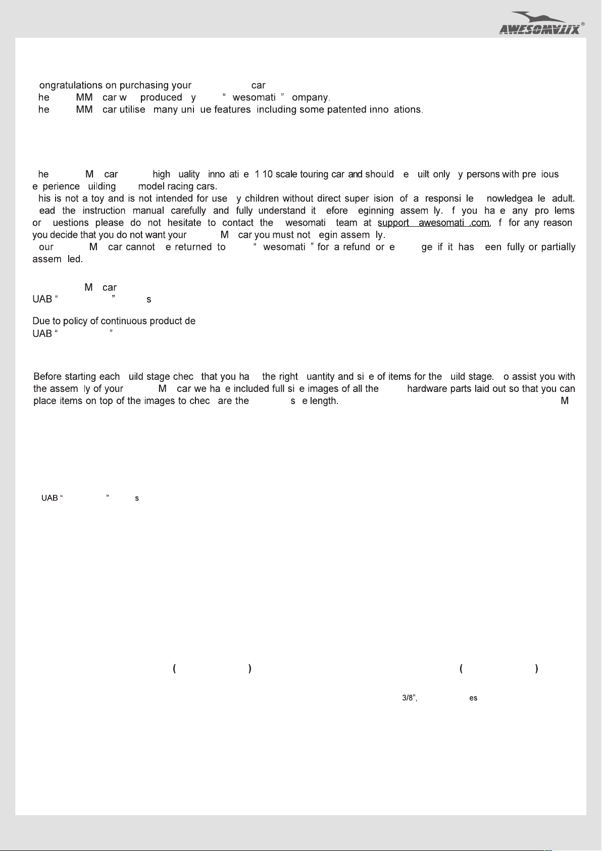
STEP 1
ST03
SB3X5
AM14LS
AM06WL
ST03
SH1.75
AT21ST-A
SH1.0
SB3X6
ST03
SH1.75
SH1.75
ST24
SB3X5
AM23-1
AM06WL
ST03
SH1.75
SH1.75
SH1.0
SH1.0
ST24
ST03
Note the difference between
ST03 and ST24 all tuds!
STEP 1
FINISHED
ST24
Note: The last turns of the lower ST03 all tuds and
SB3X5 screws can be tight. rew them with for e.
SB3X5 M3x5 Button Head Screw x4
SB3X6 M3x6 Button Head Screw x2
6x3x1mm Spacer (Gray) x6
SH1.0
SH1.75 6x3x1.75mm Spacer (Black) x10
AT21ST-A
Pivot Ball x2
ST03 Ball Stud x8
AM06WL Steering Block x4
AM14LS Steering Arm x2
AM23-1 Rear Steering Arm x2
ST24 4,8mm Ball Stud x4
Note: se other combinations of SH0.5, SH1.0 a d SH1.75 acers nder a propr a e
Pivot Balls and Ball Studs to adjust your car set-up to better suit different track conditions.
Make Rear Right
and Rear Left.
Make Front Right
and Front Left.
3
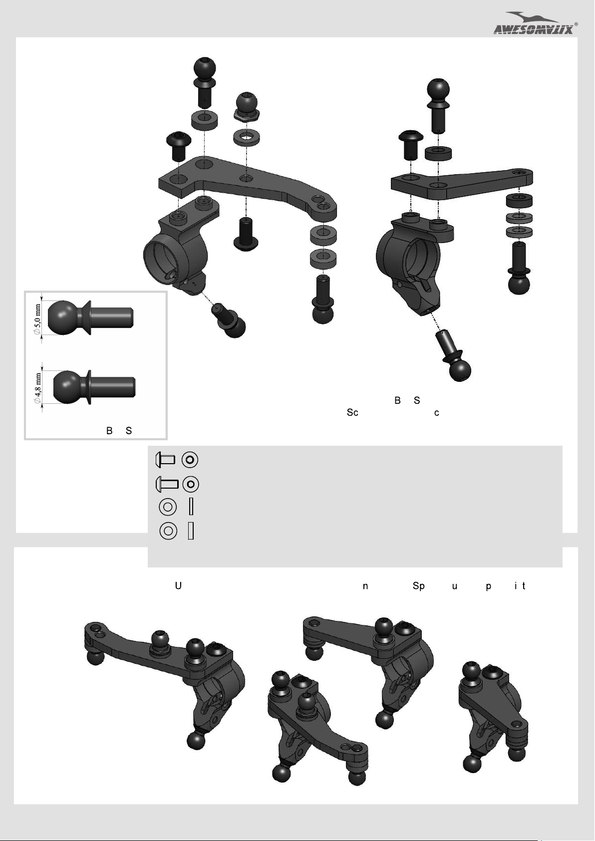
STEP 2
Thread Lock
SPR07
B415
ST116
B415
PIN01
SPR07
Attention!
Note the mutua orientation of ST16 at
rewing of ST38
The pins of both ST16 hou d be ara e
to each other The recommended wrench
for screwing of ST38 is 3/8 US standard
wrench (~9,53 mm).
Apply Joint Grease to
the rubbing surfaces.
ST113
ST38
Version of the front Universals
ST16
ST17-1
PIN01
for US-spec kits.
S 17
ST16
ST113
PIN01
ST01
ST16
P20
ST01
ST16
PIN01
PIN01
1. Insert a 2.5mm flat screwdriver tip
into ST17 Universal Ring slot, bend of
the lug and turn screwdriver through 90 deg.
2. Take out/insert ST16 U-Joint Cross from/
into unclamped ST17 Universal Ring.
ST38
S 17
STEP 2
FINISHED
Make 2 Front Universals.
PIN01 1.5x7.8 Pin x6
SPR07 E-Ring x4
B415 ea ing x4
ST116 IFJ/IRJ Cross
Front Universals for US-spec kits.
x2
ST01 Front Axle x2
ST16 U-Joint Cross
ST17-1 Universal Ring
x4
x2
ST113 Front Universal Bone x2
ST38 Universals Nut x4
4
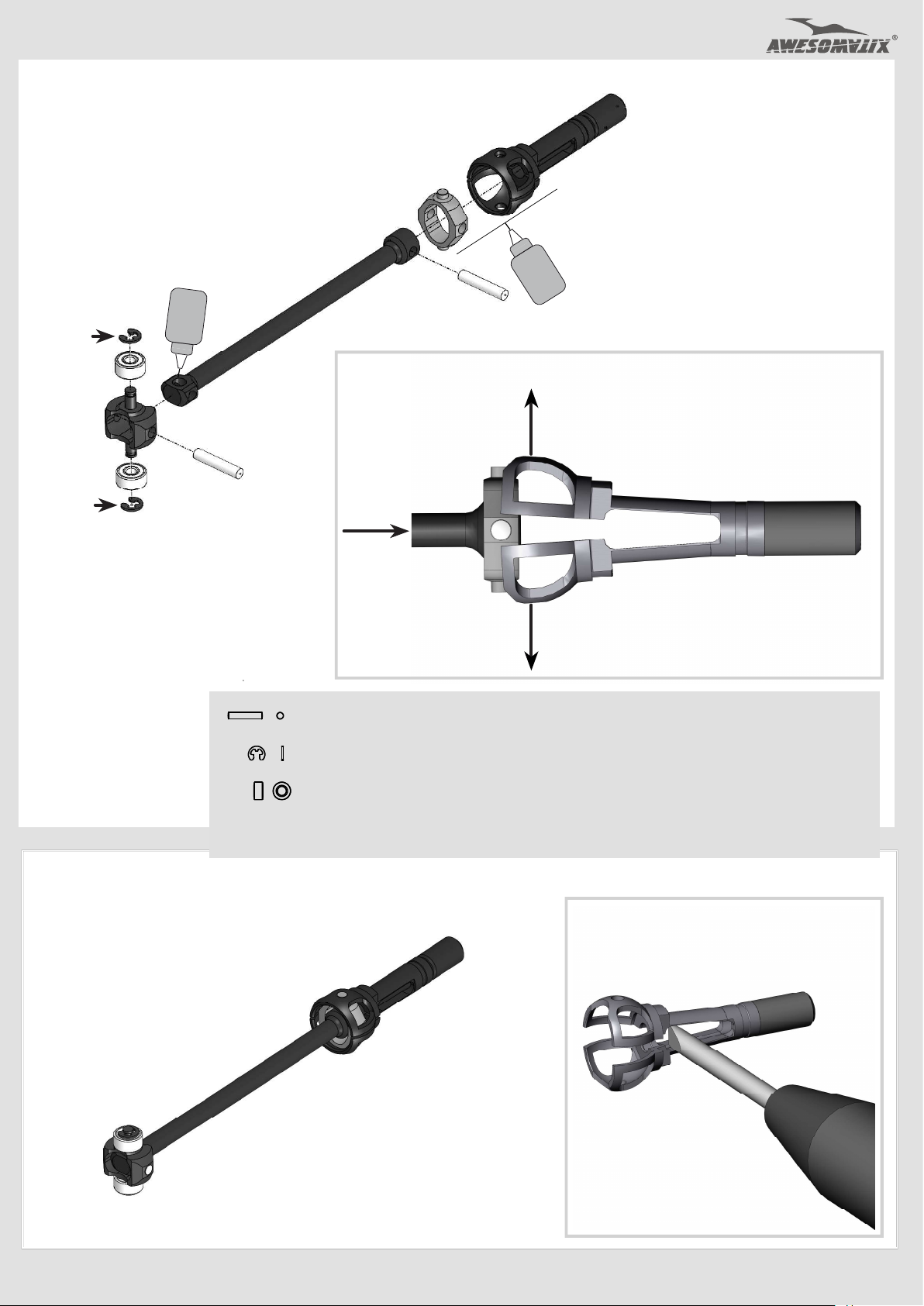
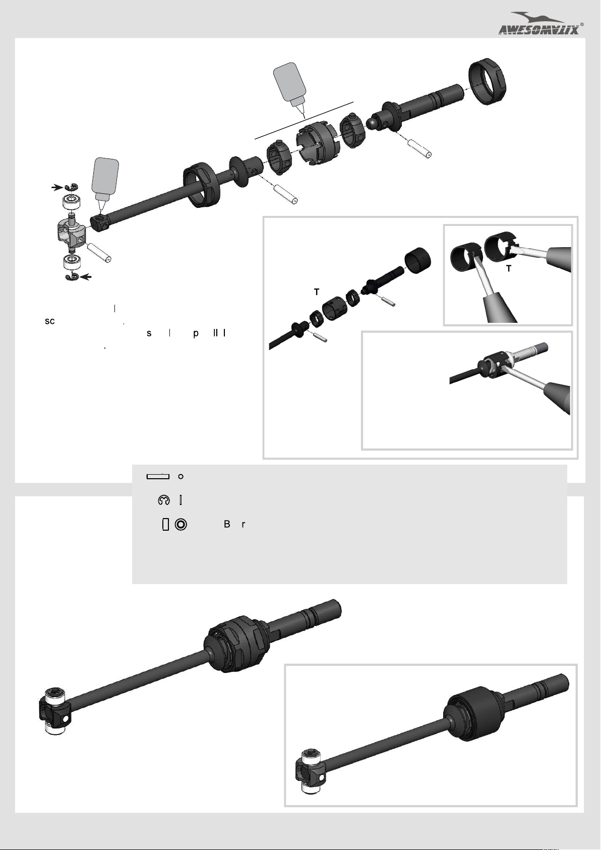
STEP 3
SPR07
Thread Lock
ST114
ST02
ST16
Apply Joint Grease to
the rubbing surfaces.
PIN01
B415
ST116
B415
SPR07
PIN01
PIN01 1.5x7.8 Pin x4
SPR07 E-Ring x4
B415 Bearing x4
Assembling/disassembling method
1. Unclamp ST02 Rear Axle a bit.
2. Take out/insert ST16 U-Joint Cross
from/into unclamped ST02 Rear Axle.
ST02 Rear Axle x2
ST16 U-Joint Cross x2
ST114 Rear Universal Bone x2
STEP 3
FINISHED
ST116 IFJ/IRJ Cross x2
Tip:
Use a 2.5mm flat screwdriver
to unclamp ST02 Rear Axle.
Make 2 Rear Universals.
5

STEP 4
Note: We recommend to install SC2X6 screws
only at high traction conditions.
STEP 4
FINISHED
B106RS
SC2X6
B106RS
SH0.1
AT13
P16
B106RS MR106RS Bearing x8
SC2X6 M2x6 Ca Head Screw x4
P16 Lock Ring x4
Make 2 Rear.
B106RS
SC2X6
B106RS
SH0.1
AT13
A
T13 Wheel Hex x4
SH0.1 6x8x0.1mm Shim x4
P16
Make 2 Front.
Note: Rear Universals may be a bit tight at this
stage. But don t worry Rear Universals take
its true position after the wheels .
STEP 5
C04M1+9.0
Note the difference!
C04M1+8.0
Note:
P04 have the tight fit in the C04M1+8.0 and C04M1+9.0 arms.
SB25X8 ST03 b
Achieve a free action of the ball joint with a minimal backlash.
SB25X8 M2.5x8 Button Head Screw x8
C04M1+8.0 Suspension Arm x2
C04M1+9.0 Suspension Arm x2
P04 Arm Hasp x4
P04
C04M1+9.0 for front !
C04M1+8.0 for rear !
SB25X8 x2
P16
Note: Press P16 Lock Ring on the Axle to fix it.
For disassembly hit the of the Axle
or press .
STEP 5 FINISHED
Make Front Right
and Front Left.
Make Rear
Right and Rear Left.
6
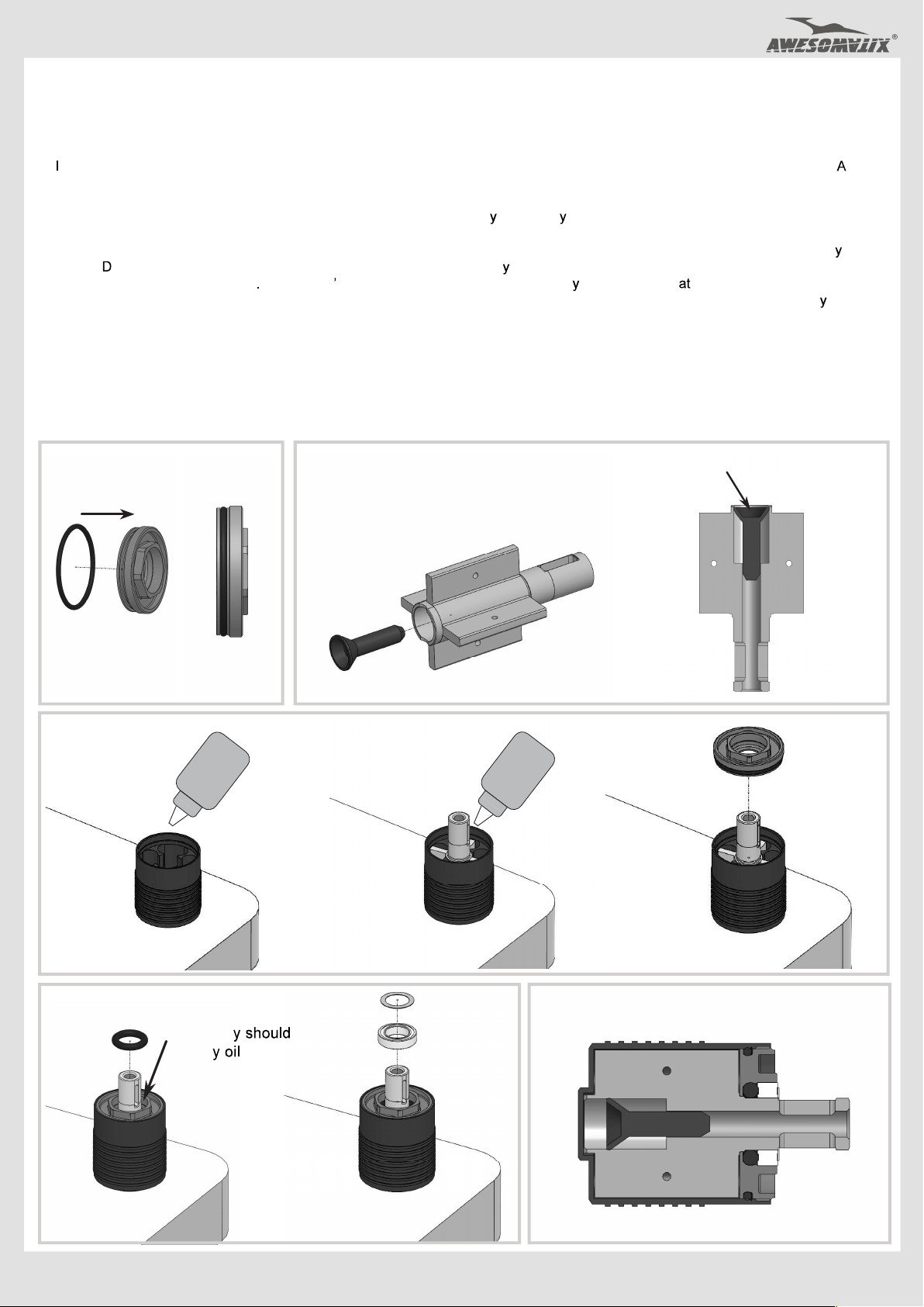
Assembling of the Dampers
Note: We recommend to use 450 cst pure silicone oil for D2.2-S-P dampers of this kit.
1) Stretch and place OR18V O-ring in the groove of the AT40-1 Cup.
2) nsert P63 Piston into AT41-2 Vane cavity. Align the outer face of P63 Piston with the outer edge of AT41-2 Vane cavity. Keep T41-2
in vertical position and add a drop of oil into outer conical hollow of P63 Piston to fill this hollow fully.
3) Stand AT42-1 Case up and fill ~1/2 of volume with the desirable silicone oil. Insert AT41-2 Vane into AT42-1 Case slowly full way down.
4) Add more silicone oil. The oil should cover the AT41-2 Vane completel . It is highl recommended the damper should be placed into a
shock air remover. Otherwise let the damper sit for 30m+ to allow air bubbles to escape.
5) With the damper still exactly vertical (important !), screw AT40-1 Cup into the AT42-1 Case with a 9mm socket wrench until full
threaded. o not force the AT40-1 Cup - once aligned, it will screw on easil . The excessive oil should go out through the gap
between AT40-1 and AT41-2 Vane Please don t remove this oil from the bearing cavit of AT40-1 Cup this stage!
6) Place OR155V O-ring into AT40-1 Cup. You can use a piece of an appropriate tube to press o-ring slowly and fully into cavit .
7) Place B85 bearing and one SH5X7X0.1 shim onto AT41-2 Vane output shaft.
8) Clean up oil off the outer surface of damper.
For disassembling please do all steps in the reverse order.
1)
OR18V
3)
AT42-1
AT40-1
2)
P63
P45R
4)
OIL OIL
AT41-2
P45
Put a drop of the silicone oil into
conical hollow of P63 piston.
AT41-2
5)
AT40-1
6)
OR155V
This cavit be
filled b before
o-ring installation.
7)
SH5X7X0.1
B85
7
CUTAWAY VIEW

STEP 6
SC2X6
SRS
SPR03
P46R
D2.2-S-P
AM17XL/R
Note: P46R ball should be placed
between SRS screw and ST69-00 screw.
SC2X6 M2x6 Ca Head Screw x4
STEP 6
cont d
Attention! fter installation of SPR02X rotate the complete D2.2-S-P damper within AM17XR/L
until the maximum up travel is reached ecure SC2X6 screw in the AM17X/RL after that.
SPR02X AM17X/RL !!!
SRS Spring Rating Screw x4
SS3X3 Set Screw x4
SPR03
AT119
ST69-00
O ST69-15 and ST69-25 screw
Shock Pointer x4
SPR02X
SS3X3
are .
AM17XR Damper Holder Right x2
AM17XL Damper Holder Left x2
D2.2-S-P Damper x4
SPR01 STD Shock pring x4
SPR02X Shock Rod Guide x4
ST69-00 Ride ght crew x4
AT119 Spring crew older x4
P46R Ball Piston x4
STEPS 6
FINISHED
Up travel position of SPR02X.
SPR01
Assemble 2 Right hocks
and 2 Left hocks.
Note:
Initial position of ST69-0 crew is ~0,6mm.
8

STEP 7
Note: C01B-X-MM2 Carbon Lower Deck is used in A800MMX kit.
C01B-X-MMA Alloy Lower Deck is used in A800MMXA kit.
SH1.75 x4
SF3X6 x4
REAR
STEP 7 FINISHED
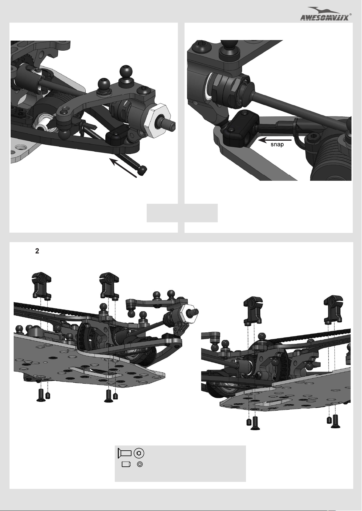
Snap P03 Ball Cups gently on AT21ST-A Balls.
P03 x4
ST-A x4
D SF3X6
AT21ST-A
SF3X6 M3x6 Flat Head Screw x8
SH1.75
SH1.75 x4
SF3X6 x4
6x3x1.75mm Spacer (Black) x8
P03 x4
Crimp P03
if
ST-A x4
FRONT
P03 rm Ball Cap x8
AT21ST-A Pi ot Ball x8
Note: se other combinations of SH0.5, SH1.0 a d SH1.75
acers nder a propr a e AT21ST-A balls to adjust your car set-up.
STEP 8
Install two ST24 all Studs
on two rear AM78X1 Bulkheads.
AM78X1 x2
ST24 x2
SF3X5 M3x6 Flat Head Screw x14 ST24 4,8mm Ball Stud x2
AM177 Motor Mount x1
AM78X1 Bulkhead x4
P56 Antenna Holder x1
SF3X5
5 4 3 2 1
Motor mount screws designation for setup sheet
AM78X1 x2
AM177
P56
AM78X1 x2
FRONTREAR
SF3X5 x4
SF3X5 x6
SF3X5 x4
9

STEP 9 STEP 10
P39
G07
WA02
G07
WA02
G07
WA02
G07
WA02
G08
ST31-1
ST31-1
P46R
P46R
G08
WA03
hread Lock
ttention!
SC X4
STEP 11
WA03
P138
t
P 38
hread Lock
B85
OR05
SC2X4 x3
OR13
AT124B
B106RS
OR05M
OR13
B106RS MR106RS Bearing x2
B85 MR85 Bearing x2
OR05 O-Ring
OR06 O-Ring
x2
x2
P46R Piston x2
PIN02 1,5x5,8 Pin
x2
SC2X4 M2x4 Cap Head screw x3
B85
OR05
AT123B
B106RS
OR06
ST23X
PIN02
AT123B GD2B Case1 x1
AT124B GD2B Case2 x1
P138 38T Pulley x1
ST23X IRJ Outdrive x2
ST31-1 GD2 Output Axle x2
P39 GD2 Cross Pin x1
OR13 13 mm -Ring x1
G07 GD2 Satellite Gear x4
G08 GD2 Bevel Gear x1
WA02 3.5x9.5x0.2 Washe x4
WA03 5x15.5x0.3 Washer x2
Fill with desirable silicone oil (not included).
Screw
The excessive oil will go out through the
AT123B
Diff Oil
oil level
GD2B Case with 10mm wrench slowly.
ST31-1
Note the initial position
of
P46R
piston in this
ST31-1
axle.
axial hole.
STEP 12
PIN02
ST23X
OR06
P46R
B106RS
10
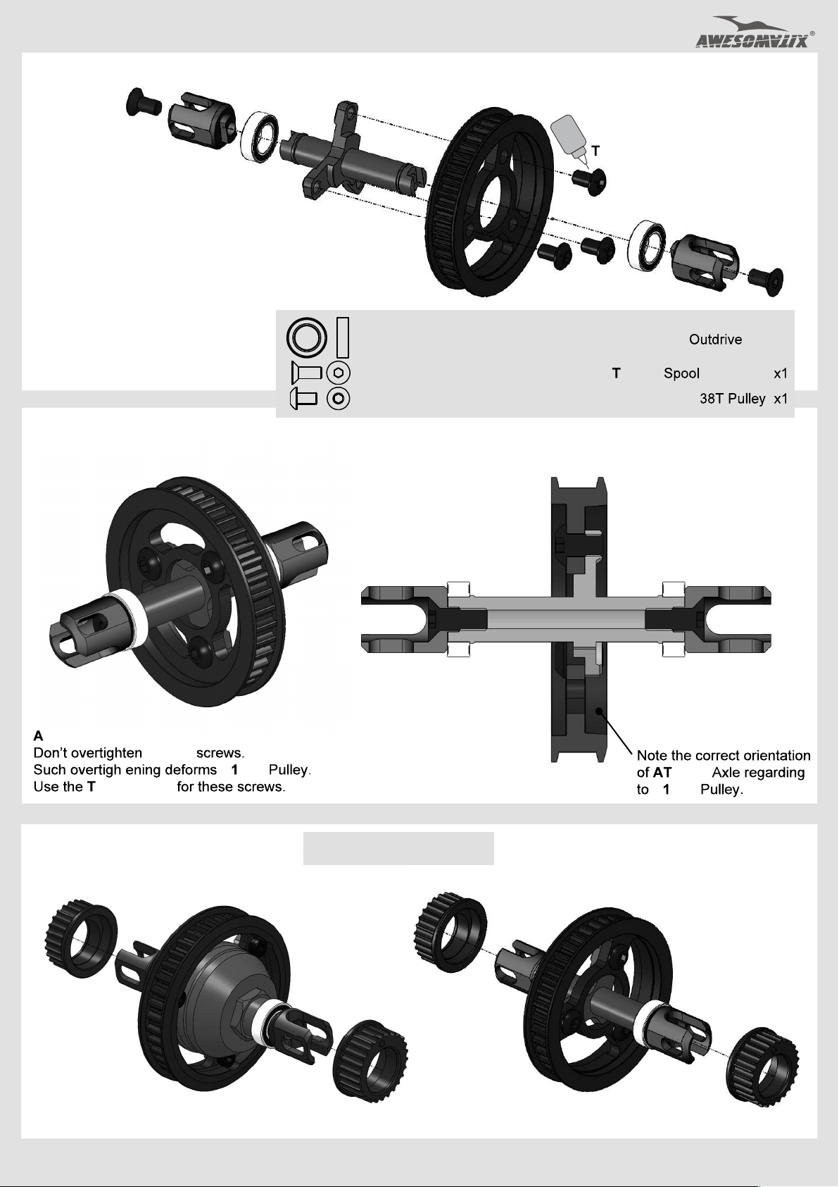
STEP 13
SF3X8
ST37X
STEP 13 FINISHED
B106RS
AT03BX
P138S
SB3X5 x3
B106RS MR106RS Bearing x2
SF3X8 M3x8 Flat Head Screw x2
SB3X5 M3x5 Button Head Screw x3
hread Lock
B106RS
ST37X
SF3X8
ST37X Spool x2
A 03BX Axle
P138S Spool
ttention!
hread Lock
STEP 14
P110
t
SC3X5
P 38S
P110 Bearing Housing x4
P110
P110
03BX
P 38S
P110
11

STEP 15
STEP 16
Attention! Note orientation
of this chamfer on DT22.
DT22
SB3X8
AM88L
REAR
Attention!
Don’t tighten SB3X8
screws on this stage.
STEP 17
SB3X5 x4
AM88R
AT120XB
AT62-5M
SB3X8
B106RS
SB3X5 M3x5 Button Head Screw x8
SB25X8 M2.5x8 Button Head Screw x1
SB3X8 M3x8 Button Head Screw x2
SB3X5 x4
AM19-FX x2
SB25X8
AT120-5
B84RS
AT120XB
Note: AT120XB is fully factory
assembled for your kit.
AM88R Shock Holder R x1
AM88L Shock Holder R x1
AT120XB 20T Alloy Pulley x1
AM19-FX Upper Arm Holder x4
BEL351B Belt 351 mm x2
AM19-FX x2
Note order of belts!
Front belt
BEL351B
BEL351B
B73SS all bearing x2
SH0.5 6x3x0.5mm Spacer (Silver) x2
ST59 LS2 Long Screw x1
Initial position of rear
P110
B73SS x2
SH0.5
SH0.5
Initial position of front
ST59
P110
Rear belt
12

STEP 18
SB3X5AL
ST24
SB3X10
SH1.0
STEP 19
ST118
SH0.5
AM 52
AT21ST-A x2
ST24
AM180
SF3X5 x2
Use SB3X5AL s re as a steering
imiter (usually on carpet tracks).
AM180 Be ran position an e
changed via shi t ng of ST118 Axle
ithin 1mm range or a justing of
the Ackermann setting. We recommend the rearward
position for carpet and the forward position for asphalt tracks.
SFX5 M3x5 Flay Head Screw x4
SB3X10 M3x10 Button Head Screw x1
SF3X10 M3x10 Flat Head Screw x4
SH0.5 6x3x0.5mm Spacer (Silver) x1
SH1.0 6x3x1mm Spacer (Gray) x1
Attention!
Tighten SB3X8 screws of
AM88L/R with 2mm ball
hex driver after tightening
of SF3X10 screws.
SF3X5 x2
ST118
AM180 SB Bellcrank x1
AM152 SB Stan x1
ST118 SB Be ran Ax e x1
ST24 4,8x6mm Ball Stud x1
AT21ST-A Pi ot Ba x2
FRONT
SF3X10
REAR
STEP 19 FINISHED
REAR
The pins of AM17 should e covered
y AM88R/L Shock Holders.
13
SF3X10
FRONT

STEP 20
M05C
SB3X6 x2
Note: C127S Top Decks are used in A800MMXA kit.
C127 Top Decks are used in A800MMX kit.
ST019
ST019 x2
SB3X5 x4
C127
C127
ST019
SB3X5 x4
ST019
FRONT
op decks
holes designation
for setup sheet
A
B
C
D
E
F
STEP 21
REAR
C127 Top Deck x2
AM05C Rear Holder x1
ST24 4
recess
Note the orientation of recesses
on the C127/C127S Top e ks.
SH1.0 x4
SH1.75 x4
6x3x1mm Spacer (Gray) x12
SH1.0
REAR
SB3X5 M3x5 Button Head Screw x8
SB3X6 M3x6 Button Head Screw x2
ST019 Top Deck Screw x3
ST24 4
SH1.0 x8
SH1.75 x4
FRONT
ST24 4,8 6 Ball St d x8
SH1.75
6x3x1.75mm Spacer (Black) x8
STEP 22 STEP 22 FINISHED
P07
P07
P07 Arm Clip x8
T SF3X6
AT21ST-A
14
STEP 23 STEP 23 FINISHED
ST05L
STEP 4
P12X
P12X
ST05L Shock Rod x4
P12X
P12X
SF3X8
SS3X5
SF3X8
SS3X5
SS3X5
SF3X8 M3x8 Flat head Screw x4
SS3X5 M3x5 Set Screw x4
P12X Sway Bar Holder x4
15
SF3X8
SS3X5
SF3X8

STEP 25
Attention!
The deflected tips of Sway Bar
should be directed downwards.
SWB10...SWB12
Cut upper leg of P12X
high roll
centers setups.
re ove
SS3X3
AT142
STEP 25 cont d
P05
B63SS
SWB10...SWB12
U igger hole for
SB1 Sway Bars.
maller hole for
SB10 and SB11
Sway Bars.
Note:
SWB12 - two strips
SWB11 - one strip
SWB10 - no strip
SS3X3 M3x3 Set Screw x4
B63SS MR63ZZ Bearing x4
B63SS
Note:
Don t tighten SS3X3 Set Screws at this stage.
SS3X3
AT142
SWB10....SWB12 Sway Bar x2
P05 Sway Bar Joint x4
AT142 Sway Bar Stopper x4
STEP 25 FINISHED
REAR
FRONT
Adjust AT142 Stoppers disposal to reach the centered position
of the Sway Bars and tighten SS3X3 Set Screws after that.
16

STEP 26
Servo rod or lon
servo l nk la out
9,8 mm
P13-4
Front left
upper arm
P02
P01
P13-4
Make 4
30,5 mm 30,5 mm
AT25-44
AT14
snap
Front left rod
P13-4
P13-4
AT14
Make 2 rear rods
P13-4 AT25
Front right rod
P13-4
P13-4
Turnbuckle x9
AT14
18,3 mm
AT25-44
AT14
AT25 Turnbuckle x2
AT25-44 Turnbuckle x2
P01 Ball Joint 1 x4
P02 Ball Joint 2 x4
P13-4 Ball End x18
P13-4
P13-4
P13-4
Front right
upper arm
AT14
AT14
AT14
Rear right
upper arm
Rear left
upper arm
AT14
AT14
AT14
P13-4
P13-4
P13-4
P13-4
P13-4
P13-4
Notes: The given rods and arms sizes are approximately for 4° front caster and 0° rear caster, 2° both front and rear
cambers, 3,0° rear toe-in and 1° front toe out angles. Use a setup station or angles gauge for further precise suspension
geometry setting. See our recommendations on page #23 for quick and easy suspension geometry change.
Snap all upper arms, front and rear rods.
17

STEP 27
SB3X10
Note:
Use the appropriate combination of
SH
spacers for sufficient gap between
battery and
P25
SB3X10
Cla ps.
SF3X10 x2
P25
SH0.5...SH1.0
AM15-3
P23
SF3X6
SH0.5
SB3X8
SH1.75 x2
BATTERY
AT12
P25
SH0.5...SH1.75
P23
AM15-1
SH0.5
SB3X8
SH0.5...SH1.75
SF3X6
SH1.75 x2
SB3X10
P25
AM15-3
P23
SF3X10 x2
P25
AM15-3
Battery Holders adjustment:
Choose the desirable battery position.
Tighten up
P23
Adjust
SF3X10
Battery Holders.
SF3X6
screws to achieve ~0.5mm
screws to fix
clearance between them and the battery.
ST110
and
ST105 Round Weights
should e used for adjusting
of the final weight and the weight distribution of the car.
ST105
SF3X10 M3x10 Flat Head Screw x4
SF3X6 M3x6 Flat Head Screw x2
SB3X10 M3x10 Button Head Screw x2
SB3X8 M3x8 Button Head Screw x2
s
ST110
and
ST105
The en raved sides of
The opposite sides are chamfered.
P23 Outer atter Holder x2
P25 atter Cla p x2
AM15-3 Battery Nut x2
SH0.5 SH1.0 SH1.75 Spacers
ST110 or ST105
.
ST110
and
ST105
are flat.
ST110
ST110
18
ST110 10g
Round Weight
ST105 5g
Round Weight

STEP28
Servo (not included)
AM24-8
SB3X5 x2
SH0.5 x2
SB3X5
SH1.75 x3..4
AT21ST-A
SB3X5
SB3X12
For lon servo l nk la out
Note: Recommended length of the servo horn at the lon servo l nk la out 6 .
Recommended length of the servo horn at the hort servo l nk la out ~ .
Attention! Neutral servo arm position
at lon servo l nk la out.
SH0.5
SB3X12 M3x12 Button Head Screw x1
SF3X5
SB3X5
M3x Flat Head Screw x3
M3x5 Button Head Screw x4
S H0.5 6x3x0.5mm Spacer (Silver) x3
S H1.75 6x3x1.75mm Spacer (Black) x4
Short servo link layout
SF3X5 x3
AT 2 1 S T - A Pi vo t B a l l x1
AM 2 4 - 8 S er v o H o l de r x 1
15mm servo horn
Long servo link layout
Snap servo rod.
Use th s hole o AM180
and SH0.5+SH1.75 s a ers
19
Cut two P13-4 and use
SS3X12 as a turnbuckle.

STEP 9
SPR05
SH1.75
P14-2
OR06
SB3X6 x2
OR06
P14-2
SH1.75
P14-5
SPR05
~1 7m m
OR06
SPR05
P14-2
Attention!
ke e
P14-1 b k e e e e
e e e e
OR06
SPR05
STEP 30
SB3X12
SF3X8
AM05-2
P15L
P14-1X
SB3X12
OR06
or
OR18 dependin of the
spur gear thickness
P14-2
SB3X8
SB3X12 M3x12 Button Head Screw x2
SF3X8 M3x8 Flat Head Screw x3
SB 3X 8 M3x8B ut ton Head Screw x2
SB3X6 M3x6 Button Head Screw x2
OR06 5mm O-Ring x4
Motor
(not included)
T55M
SB3X8
P14-1X L ower B umper x1
P14-2 Body Post x4
P14-5 U e u e x1
P15L Foam Bumper x1
SPR05 Body Clip x4
Pinion Gear
(not included)
Spur Gear
(not included)
STEP 31
FINAL ASSEMBLY
Install:
Speed controller (not included),
Receiver (not included),
Battery (not included)
Wheels (not included)
T55
+OR06
or OR18
T55M
OR06
or
OR18 dependin of the spur
ear thickness
ST110 1 g and ST105 5g Round Weights can
be installed to achieve the desirable car weight
and the center of gravit position.
20
SH0.5 x2
SB3X10 x2

Optional parts and sets
AT22M Rear Body Holder
Use the extra clipped
P14-2 bars for additional
support of body s tail.
clipped P14-2
clipped P14-2
AM105, AM105 Stiffener
SF3X5
A 22M
SB3X8
SB3X6
HRB Horizontal Rear Bodypost Set
SB3X10
AT139 Fan Holder
C05-H
P14-2
M126
SB3X6 x2
SH0.5 x2
SB3X6 x2
C26 Top Stiffener
P14-2
SB3X10
AM105 or AM105
SF3X5
BW7, BW8, BW10 Weights
SB 5X8
SB 5X8
BW 0
SB3X8
SH1.75 x
SB3X12
Fan (not included)
AM111 Belt Anti Skip
SB3X5
B73SS
SB3X6 x2
C26
AT139
SB3X10
BC1 Battery Clamp Set
AM12 , AT144
SB3X6
P21
AT26 or AT144
AM111
SH0.5...SH1,75
BW7
SB3X8
BW8
SB 5X8
SB 5X8
SS3X12
SB 5X6
AM111
AM12
AT139 Fan Holder (optional)
21

SUSPENSION SETTING TECHNIQUE
Camber adjustment rule: both
i dds °
o amber at onstant aster
Caster measuring:
C ° =
(H1-H2)*1.5 for front
(H1-H2)*2.2 for rear
Caster adjustment rule: front
and rear u er rod 0.5mm i
dds ° of aster at constant camber
Reactive Caster setting is ossible.
H1
Roll Center adjustment:
se combinations of SH0.5, SH1.0 a d SH1.75 acers
nder a propr a e Pivot Balls and Ball Studs or
this adjustment
H2
Adjust these spacers for
Bump Steer control.
se SS3X4 screws
for Upstop and
Downstop setting.
Wheelbase adjustment:
se rear sus ension aster ange for this adjustment.
Adding 4°caster shortens wheelbase by 1mm.
Use Ride Height Gauge for U
&
22

SHOCK SETTING TECHNIQUE
Attention!
D
1. Damping and Shock Spring rate setting
Increase A-distance ( lide hock outward) to increase
Dampin and prin rates simultaneously and concor y
to each other. A-distance range is 0 - 4.0mm.
Use SF3X10 Screw to unlock Shock and to lock it at the
desirable position.
Decrease B distance (slide AT119 pring crew Holder outward)
to increase Spring rate at the fixed Damping rate value.
Use SRS (Spring Rating Screw) to unlock AT119 pring crew
Holder and to lock it at the desirable position.
2. Shock Spring preload setting
Spring preload and the ride height of the car is adjusting
via
RHS
(Ride Height Screw).
Attention!
In this kit
Turn IN (CW)
Turn OUT (CCW)
Use prin preload settin to adjust ri he value.
ST69-00
RHS
screw to increase sprin preload.
RHS
screw to decrease prin preload.
screw is us as
RHS screw.
SF3X10
3. SRS/RHS Screws arrangements change
The reverse arrangement of these screws is possible also.
B
SRS/RHS Screws arrangement I SRS/RHS Screws arrangement II
4. Using of DG1X Damper Gauge
RHS
RHS
SRS
SRS
obes (4 s)
2
obes (5 s)
Sa le o 3 4
size A setting
DG1X
23
Sa le o 1 4
size B setting
DG1X

GRAPHS OF THE SUSPENSION STIFFNESS DEPENDING ON THE POSITION
OF THE DAMPER SIZE A AND SHOCK SCREW HOLDER SIZE B
Suspension rate, gF/mm (vertical force / vertical displacement of the wheel)
200
190
180
170
160
150
140
130
120
110
100
90
FOR SPR01 SPRINGS
80
70
60
50
0 1 2 3 4 5 6 7
SRS/RHS Screws arrangement I
0
15
0 1 2 3 4
SRS/RHS Screws arrangement II
FOR SPR01S SOFT SPRINGS
140
130
120
110
100
B, mm
5
4
3
2
1
0
A, mm
90
80
70
60
50
40
0
1 2 3 4 5 6 7
SRS/RHS Screws arrangement I
B, mm
0 1 2 3 4
SRS/RHS Screws arrangement II
24
5
4
3
2
1
0
A, mm

FINAL DRIVE RATIO CHART
dp
dp
25
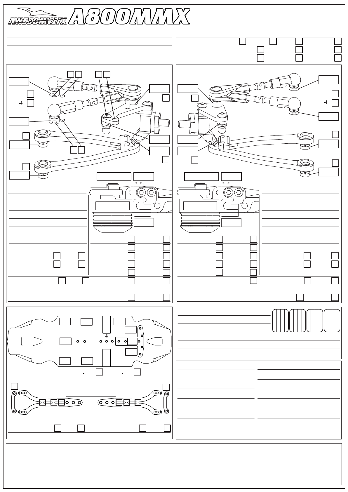
A800MMX
SETUP SHEET
NAME
COUNTRY
RACE
TRACK
DATE TEMP. °C AIR / TRACK /
ASPHALT OUTDOOR INDOOR CARPET
TRACK CONDITION TECHNICAL MIXED FAST
TRACTION LOW MEDIUM HIGH
FRONT REAR
MM
AM19-2
AM19 X
MM
AT21
MM
AT21
MM
CAMBER ANGLE / °
CASTER ANGLE / °
TOE ANGLE / °
RIDE HEIGHT / MM
DOWNSTOP / MM
UPWNSTOP / MM ROTOR STD
STABILIZER Ø / MM SPRING STD S
LOW ARM C04M1+9.0 DAMPER D2.2
STEER. ARM AM14LS SRS/RHS ARR. I II
WHEEL SPACER / MM
FRONT DRIVE SPOOL GB2B LOW
DIFF. OIL
DIFF WASHERS
OIL OIL
PSS SETUP 25% 15%
WHEELHUB AM06WL
GF/MM MM GF/MM MM
AT13W
SC2X6
MM MM
SHOCKS SET SHOCKS SET
HIGH
MM
MM
MM
MM
AT13W
MM
MM
SC2X6
CAMBER ANGLE / °
CASTER ANGLE / °
TOE ANGLE / °
RIDE HEIGHT / MM
DOWNSTOP / MM
ROTOR STD UPWNSTOP / MM
SPRING STD S STABILIZER Ø / MM
DAMPER D2.2 LOW ARM C04M1+8.0
SRS/RHS ARR. I II STEER. ARM AM23-1
PSS SETUP 25% 15%
REAR DRIVE GB2B
DIFF. OIL DIFF WASHERS
WHEEL SPACER / MM
WHEELHUB AM06WL
AM19 X
LOW
MM
AM19-2
MM
AT21
MM
AT21
MM
HIGH
CHASSIS FLEX AND WEIGHT SETTINGS
g
g
g
LOWE R D ECK C01B-X MM2 C01B-X MMA
C26
g
1 2 3 5
MOTORMOUNT SCREWS
g
A B C D E F
FRONT REAR
TOP DECK CUTS
FRO NT TOP DECK C12 7 C127S
COMMENTS:
ST019
REA R TOP D ECK C127 C12 7S
Editable setup sheet can be downloaded from:
g
g
g
g
AM105 SCREWS
TOP DECK CUTS
http://site.petitrc.com/reglages/awesomatix/SetupSheetsAwesomatixA800.html
TIRES
INSERTS
WHEELS
ADDITIVE TIME - FR RR
TOTAL W EIG HT WEI GHT DIS TRIBUTION F % R %
NOTES:
MOTOR LATERAL SH IFT / MM
MOTOR SERV O
C26
SPUR PINION RATIO STEER TRAVEL IN OUT
BODY BATTERY
WING RECEIVER
ESC RADIO
ESC SETTING
BEST LAPTI ME QUALIF./FINAL POSITION /
ACKERMA NN SHIMS / MM
Standard Spare Parts
Optional Parts
Parts# Description
AM05C Rear Holder
AM06WL Steerin Block
AM08-3 Shocks Holder
AM14LS Steerin Arm
AM15-3 Batter Nut
AM17XL amper Holder L
AM17XR amper Holder R
AM19-
AM23-1
AM24-8
AM78X1 Bulkhead
AM88R Shock Holder R
AM88L Shock Holder L
AM152 S Stand
AM177 Motor Mount
AM180 SB Bellcrank
AT03BX Spool Axle
AT13 Wheel Hex
AT14 Turnbuckle
AT21ST-A Pivot Ball Steel
AT25
AT25-44
AT40-1 Damper Cup
AT41-2 Damper Vane
AT42-1 Damper Case
AT55M Spur Nut
AT119 Spring Screw Holder
AT120XB 20T Allo Pulle
AT123B G 2B Case1
AT124B G 2B Case2
AT142 Sway Bar Stopper
ST01 Front Axle
ST02 Rear Axle
ST03 Ball Stud
ST05L Shock Rod
ST113 IFJ Universal Bone
ST114 IRJ Universal Bone
ST116 IFJ/IRJ Cross
ST16 U-Joint Cross
ST17-1 Universal Rin
ST019 Top Deck Screw
ST23X IRJ Outdrive
ST24 4,8x6mm Ball Stud
ST31-1 G 2 Output Axle
ST37X IFJ Outdrive
ST38 Universal Nut
ST59 LS2 Long Screw
ST69-00 Linear Spring Screw
ST105 5g Round Wei ht
ST110 10g Round Wei ht
ST118 SB Bellcrank Axle
G07 G 2 Satellite Gear
G08 G 2 Bevel Gear
P01 Ball Joint-1
P02 Ball Joint-2
P03 Arm Ball Cap
P04 Arm Hasp
P05 Sway Bar Joint
P07 Arm Clip
P12X
P13-4
P14 Bumper Set
Upper Arm Holder
Rear Steerin Arm
Central Servo Holder
Turnbuckle Lon
Turnbuckle 44mm
S a Bar Holder
Ball End
Parts# Description
P15L Lightweight Foam Bumper
P16 Lock Rin
P23 Outer Batter Holder
P25 Batter Clamp
P39 G 2 Cross Pin
P46R Diff Piston
P56 Antenna Holder
P58 Belt Tensioner
P63 Damper Piston
P110 Bearin Housin
P138 38T Pulle
P138S Spool 38T Pulle
C01B-X-MM2 Lo er eck Carbon
C01B-X-MMA Lo er eck Allo
C04M1+8.0 Suspension Arm
C04M1+9.0
C127
C127S
SWB10
SWB11
SWB12
SPR01
SPR02X
SPR03
SPR05
SPR07
SH0.5
SH1.0
SH1.75
SH0.1
WA02
WA03
PIN01
PIN02
OR13
OR05V
OR06
OR155V
OR18V
B106RS
B85
B84 S
B63SS
B73 S
B415
SRS
SC2X4
SC2X6
SB2.5X8
SS3X3
SS3X5
SB3X5AL
SB3X5 M3x5 Button Head Scre
SB3X6 M3x6 Button Head Scre
SB3X8 M3x8 Button Head Scre
SB3X10 M3x10 Button Head Scre
SB3X12 M3x12 Button Head Scre
SF3X5 M3x5 Flat Head Scre
SF3X6 M3x6 Flat Head Scre
SF3X8 M3x8 Flat Head Scre
SF3X10 M3x10 Flat Head Scre
BEL351 Belt 351mm Bando
G1X amper Gua e Set
STS-A800MMX A800MMX Stickers Sheet
Suspension Arm
Top eck
Top eck
S a Bar 1.0mm
S a Bar 1.1mm
S a Bar 1.2mm
Shock Sprin
Shock Rod Guide
Shock Pointer
Bod Clip
E-Rin
6x3x0.5mm Spacer (Silver)
6x3x1.0mm Spacer (Gra )
6x3x1.75mm Spacer (Black)
6x8x0.1mm Shim
3x5x0.2 Washer
5x15x0.3 Washer
1.5x7.8 Pin
1.5x5.8 Pin
1x13 mm O-rin
G O-Rin
5.5mm O-ring
Damper Output O-Ring
1x8mm Damper O-rin
B106RS Ball Bearin
B85 Ball Bearing
B84 S Ball Bearin
B63ZZ Ball earin
B73 Ball earin
B415ZZ Ball Bearing
Sprin Ratin Scre
M2x4 Cap Head Scre
M2x6 Cap Head Scre
M2.5x8 Button Head Scre
M3x3 Set Scre
M3x5 Set Scre
M3x5 Alloy Screw
Parts# Description
C04M1+1.5 Suspension Arm Long
C04AL1+0.5 Alloy Suspension Arm
C04AL1+1.5 Alloy Suspension Arm
C04AL+8.0 Alloy Suspension Arm
C04AL+9.0 Alloy Suspension Arm
C05-H HRB Post Holder
C07A Carbon bumper
C25 Steerin Sti ener
C26 Top Stiffener
ST17 Universal Ring
ST24M 4,8x8mm Ball Stud
ST24L 4.8x10mm Ball Stud
ST69-15 Progressive Spring Screw
ST69-25 Progressive Spring Screw
ST121 Damper Screw
AT06 Alloy Antenna Holder
AT13W Wheel Hex Wide
AT15 Bearing Spacer
AT18 BSSX Steering Limiter
AT21 Pivot Ball
AT22M
AT40-M8
AT78
AT139
AT144
AT158
AM06M
AM12
AM14A
AM19-4X
AM19-2
AM24-20
AM87
AM105
AM105
AM111
AM126
BW7
BW8
BW10L
BW22
BW52
DT10-2-1
T10-3
OR152S
OR155
P20
P40F
P40K
P45
P138LF
P138LFS Spool 38T Pulle Lo Friction
SH3X5X0.1 3x5x0.1mm Shim
SH3X5X0.5 3x5x0.5mm Shim
SH0.25 6x3x0.25mm Spacer
SPR01S Shock Sprin Soft
SPR08 Body Support Set
SS3X4 M3x4 Set Scre
SS3X12
SWB13
T01
2.2- P
FCB
BC1 Batter Clamp Set
ABS Adjustable Body Shift Set
LS2 Linear Steering Set
BSSX Bellcrank Steering Set
HRB Horizontal Rear Bodypost Set
Rear Bod Holder
Damper Cup
Damper Piston
Fan Holder
ULCG Battery Clamp
Damper Wrench
Steering Block
Allo Batter Holder
Steering Arm
Upper Arm Holder
Upper Arm Holder
Servo Holder
Bumper Brace
Rear Stiffener 10g
Rear Stiffener 30g
Belt Anti Skip
HRB Mount
Weight 7g
Weight 8g
Weight 10g
Battery Holder 22g
Battery Holder 52g
Bearing Housing
Bearin Housin
U-Ring
Damper O-Ring
Front Universal Rin
Servo Arm (Futaba)
Servo Arm (KO)
Sponge Piston
38T Pulle Lo Friction
M3x12 Set Scre
S a Bar 1.3mm
5.5/4 mm Wrench
amper
Flexible Caster Block Set
27

WWW.AWESOMATIX.COM
UA AWESOMATIX
Email: support@awesomatix.com
All rights reserved. Copyright UA Awesomatix 2019.
 Loading...