

TM
155TM Single and 255
Dual
Cartridge Seals
Patented
n Global acceptance and satisfaction across a variety of industrial applications
n Exclusive face design for superior emissions control capability
n Stable, secure sealing under fluctuating conditions
n Patented features assure precision alignment from start-up
n Versatile and cost-effective
ISO 9001
CERTIFIED
Delivering the best value
in cartridge sealing today
CHESTERTON
®
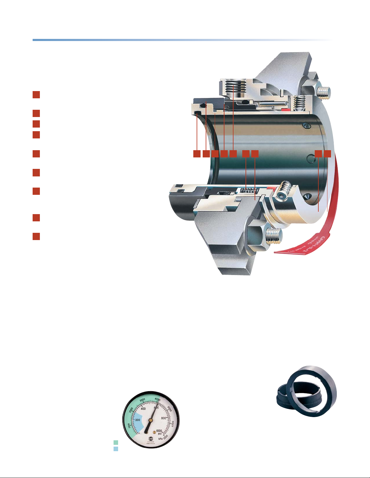
155TM
Cartridge Single Seal
Construction Details
1
All O-rings are either static or move on
non-metallic, non-fretting surfaces.
2
Seal face support shoulder is precisely square.
3
Integral drive pads cannot fall out.
4
Hydraulically balanced faces
for low frictional heat.
5
Flush port can be rotated 360° for ease
of piping as required.
6
Stationary springs, isolated from fluid
to prevent clogging.
7
Patented Adjustable Gland™
fits common bolt arrangements
without modification.
8
Self- Centering Lock Ring™
for superior concentricity.
9
Centering strap for simple installation.
1•2•3•4•5•6•7
8•9
•
•
Self-Centering Lock Ring™
ensures reliability
The patented Self-Centering Lock Ring
makes installation precise for correct face mating
and sustainable sealing. Cloverleaf 3- point
contact ensures concentricity to the shaft.
Faces start out square and stay square to prevent
the intrusion of contaminants or abrasives.
Also, constant face squareness reduces
opportunities for fluid leakage and uneven wear.
Superior reliability
during system variations
Pressure surges at start-up and
shut- down can create seal reliability
problems. The 155 seal can handle
50% to 100% greater transient
pressure than conventional seals
and provides a “margin of safety”
during normal surges.
CHESTERTON 155 Seal
Conventional Seal
Dynamic stress relief keeps faces closed
Variances in temperature or pressure, fluid phase changes,
or water hammer can create dynamically changing
stresses on the seal faces. Common face geometries
distort at the mating surface under such conditions
and create drastic wear. Chesterton face geometry
compensates for stresses in the body of the seal ring,
away from the critical face mating surfaces.
Face material
interchangeability
With the 155, the interchanging is
a fast and easy process, with seal
function and reliability assured.
Standard face materials are
silicon carbide or carbon.
The carbon can be swapped for
silicon carbide, tungsten carbide or
Duplex Carbide™, which provides the utility
of two hard faces but with lower frictional heat.
All faces are interchangeable with the
225 and 255 dual seals.
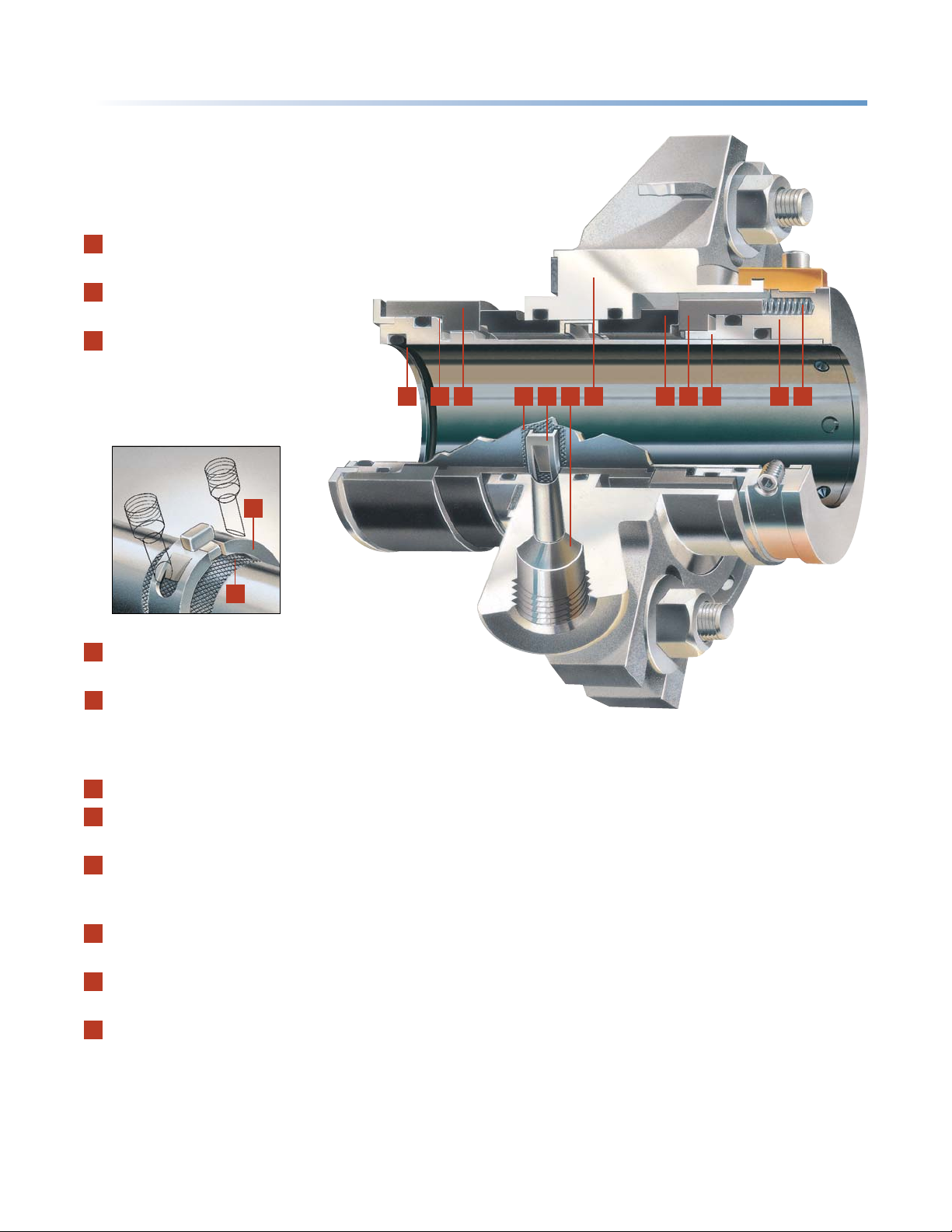
255TM
Cartridge Dual Seal
Construction Details
1
Every O-ring is either static or moves on
a non-fretting, non-metallic surface.
2
Precision seal ring support shoulder
maintains rotary alignment.
3
Inboard rotary and stationary faces.
Dynamic stress-relieving seal rings,
mated over a narrow cross-section
for low heat generation.
5
1•2•3
CHESTERTON
®
•
•
•
•
4•5•6
7
8•8• 9
10• 11
•
•
4
4
Profiled sleeve provides positive
pumping of barrier fluid.
5
Patented shuttle slides within gland to
decouple faces from gland misalignment,
channel barrier fluid, and provide anti-rotation
for stationary seal rings.
6
Barrier fluid ports provide high capacity cooling.
7
Universal gland fits majority of pumps.
ANSI oversize and API glands available.
8
Outboard stationary and rotary faces,
identical to inboard set for simple assembly,
low replacement inventory.
9
Inboard and outboard integral drive pads
cannot loosen or fall out.
10
Patented Self-Centering Lock Ring™
for superior concentricity.
11
Revolutionary Unified Seal Alignment™
requires only one set of springs to provide
constant loading of all four faces.
Springs are isolated from process and
barrier fluids.
•
Built for the future of emissions control
The Chesterton 255 seal is designed to meet
environmental regulations for emissions control.
Advanced technology for applications flexibility
The exclusive design of the 255 enables it to operate
in double-mode (barrier fluid pressure higher than
stuffing box pressure) or tandem-mode (barrier fluid
pressure lower than stuffing box pressure).
Staying cool in operation and under pressure
The 255 handles 50% to 100% more pressure than
typical seals, providing users with a “margin of safety”
at start-up and shut-down when transient surges
often occur. The 255 features an internal positive
barrier fluid pumping system with wide flow channels
for efficient removal of heat. To test the 255’s cool
running, the 255 and a widely used competitive double
seal were run under identical conditions with repeated
shutoffs. Test conditions: 1.875” (48 mm) shaft, water
barrier fluid room temperature, 1750 RPM, closed
convection system. Results: 255 ran cool and steady
while the conventional seal overheated and flashed.

CHESTERTON
®
155 STANDARD – Dimensional Data/Inch
SHAFT
SIZE
1.000 4.65 1.75 2.00 0.63 1.89 2.88 3.01 3.13 –
1.125 4.69 1.88 2.03 0.63 1.89 2.92 3.05 3.17 –
1.125*** 4.69 1.88 2.03 0.63 1.89 2.92 3.05 3.17 –
1.250 4.90 2.00 2.26 0.63 1.89 3.13 3.26 3.38 –
1.375 5.04 2.13 2.42 0.63 1.89 3.27 3.40 3.52 –
1.375*** 5.04 2.00 2.42 0.63 1.89 3.27 3.40 3.52 –
1.500 5.23 2.25 2.62 0.63 1.89 3.46 3.59 3.71 –
1.625 5.29 2.38 2.68 0.63 1.89 3.52 3.65 3.77 –
1.750 5.41 2.50 2.80 0.63 1.89 3.64 3.77 3.89 –
1.875 5.53 2.63 2.93 0.63 1.89 3.76 3.89 4.01 –
2.000 5.74 2.75 3.18 0.63 1.89 3.97 4.10 4.22 –
2.125 6.04 2.88 3.43 0.63 1.89 4.27 4.40 4.53 –
2.250 6.14 3.00 3.55 0.63 1.89 4.38 4.51 4.63 –
2.375 6.29 3.13 3.59 0.63 1.89 4.52 4.65 4.77 –
2.500 6.41 3.25 3.80 0.63 1.89 4.65 4.78 4.90 –
2.625 7.63 3.63 4.00 0.88 2.50 – 5.35 5.48 5.60
2.750 7.76 3.75 4.13 0.88 2.50 – 5.48 5.60 5.73
2.875 7.88 3.88 4.25 0.88 2.50 – 5.60 5.73 5.85
3.000 8.01 4.00 4.44 0.88 2.50 – 5.73 5.85 5.98
3.125 8.13 4.13 4.55 0.88 2.50 – 5.85 5.98 6.10
3.250 8.26 4.25 4.69 0.88 2.50 – 5.98 6.10 6.23
3.375 8.38 4.38 4.80 0.88 2.50 – 6.10 6.23 6.35
3.500 8.51 4.50 4.94 0.88 2.50 – 6.23 6.35 6.48
3.625 8.63 4.63 5.05 0.88 2.50 – 6.35 6.48 6.60
3.750 8.76 4.75 5.14 0.88 2.50 – 6.48 6.60 6.73
3.875 8.88 4.88 5.26 0.88 2.50 – 6.60 6.73 6.85
4.000 9.01 5.00 5.44 0.88 2.50 – 6.73 6.85 6.98
4.125 9.13 5.13 5.55 0.88 2.50 – 6.85 6.98 7.10
4.250 9.18 5.25 5.69 0.88 2.50 – 6.89 7.02 7.14
4.375 9.30 5.38 5.81 0.88 2.50 – 7.02 7.14 7.27
4.500 9.43 5.50 5.94 0.88 2.50 – 7.14 7.27 7.39
4.625 9.56 5.63 6.06 0.88 2.50 – 7.27 7.39 7.52
4.750 9.76 5.75 6.22 0.88 2.50 – 7.47 7.60 7.72
GLAND
OD
B
MAX
STUFFING BOX
BORE
C
MIN
MAX
C
SB
DEPTHOBLENGTH
MIN
E
F G/ MIN
BOLT CIRCLE
BY BOLT SIZE
3/8” 1/2” 5/8” 3/4”
155 STANDARD – Dimensional Data/Metric
SHAFT
SIZE
25 118 44 51 16 48 70 72 74 –
28 118 47 52 16 48 70 72 74 –
30 124 49 57 16 48 76 78 80 –
32 124 51 58 16 48 77 79 81 –
33 124 52 59 16 48 76 78 80 –
35 128 54 62 16 48 80 82 84 –
38 133 57 67 16 48 85 87 89 –
40 134 59 68 16 48 86 88 90 –
43 134 62 69 16 48 86 88 90 –
45 140 64 73 16 48 92 94 96 –
48 139 67 74 16 48 91 93 95 –
50 145 69 78 16 48 97 99 101 –
55 150 74 83 16 48 102 104 106 –
60 160 79 91 16 48 112 114 116 –
65 194 92 102 22 64 – 132 134 138
70 197 95 105 22 64 – 135 137 141
75 203 100 113 22 64 – 141 143 147
80 207 105 116 22 64 – 144 146 150
85 213 110 122 22 64 – 151 153 157
90 216 115 125 22 64 – 154 156 160
95 222 120 131 22 64 – 160 162 166
100 229 127 138 22 64 – 167 169 173
110 236 136 148 22 64 – 174 176 180
120 248 145 158 22 64 – 186 188 192
GLAND
OD
B
MAX
STUFFING BOX
BORE
C
MIN
MAX
C
SB
DEPTHOBLENGTH
MIN
E
F G/ MIN
BOLT CIRCLE
BY BOLT SIZE
8 mm 10 mm 12 mm 16 mm
G
B
155 – Standard Version
C
E
F
STANDARD MATERIALS**
Rotary Faces:
n
Silicon Carbide
n Tungsten Carbide
Stationary Faces:
n Duplex Carbide™
n Carbon
n Silicon Carbide
n Tungsten Carbide
All Metal Parts:
n
316SS
Springs:
n Hastelloy C*
O-Rings:
n Fluorocarbon installed;
EPR included
n FEPM installed;
No spares
OPERATING LIMITS
Speed Limits:
n To 4000 fpm
Temperature Limits:
n To 300°F
Ethylene Propylene
n To 400°F (205°C
Fluorocarbon, FEPM
n To 500°F
Perfluoroelastomer
Pressure Limits:
n To 600 psig
* Haynes International, Inc
Registered Trademark.
** Other materials available upon request.
*** 155T Sizes.
(
150°C
(
260°C
(
(
20 mps
)
)
)
40 bar g
)
)

155 CAST – Dimensional Data/Inch
SHAFT
SIZE
1.000 4.13 1.75 2.00 0.47 1.98 2.88 3.01 –
1.125 4.13 1.88 2.03 0.47 1.98 3.01 3.13 –
1.250 4.13 2.00 2.26 0.47 1.98 3.13 3.26 –
1.500 5.01 2.25 2.62 0.47 1.98 3.38 3.51 –
1.625 5.01 2.38 2.66 0.47 1.98 3.51 3.64 –
1.750 5.51 2.50 2.80 0.47 1.98 3.63 3.76 –
1.875 5.51 2.63 2.93 0.47 1.98 3.76 3.88 –
2.000 5.51 2.75 3.18 0.47 1.98 4.01 4.13 –
2.125 6.01 2.88 3.28 0.47 1.98 4.26 4.38 4.51
2.250 6.01 3.00 3.55 0.47 1.98 4.38 4.51 4.63
2.375 6.01 3.13 3.59 0.47 1.98 4.42 4.55 4.67
2.500 6.52 3.25 3.80 0.47 1.98 4.64 4.76 4.89
GLAND
OD
B
MAX
STUFFING BOX
BORE
C
MIN
C
MAX
SB
DEPTHOBLENGTH
MIN
E
F G/MIN
BOLT CIRCLE
BY BOLT SIZE
1/2”3/8” 5/8”
CHESTERTON
G
B
®
155 CAST – Dimensional Data/Metric
SHAFT
SIZE
25 105 44 51 12 50 72 74 76
28 105 47 52 12 50 75 77 79
30 105 49 57 12 50 76 78 80
32 105 51 58 12 50 78 80 82
33 114 52 59 12 50 79 81 83
38 127 57 67 12 50 84 86 88
40 127 59 68 12 50 86 88 90
43 127 62 69 12 50 89 91 93
45 140 64 73 12 50 90 92 94
48 140 67 74 12 50 93 95 97
50 140 69 78 12 50 95 97 99
55 153 74 83 12 50 100 102 104
60 153 79 91 12 50 111 113 115
GLAND
OD
B
MAX
STUFFING BOX
BORE
C
MIN
C
MAX
SB
DEPTHOBLENGTH
MIN
E
F
BOLT CIRCLE
BY BOLT SIZE
G/MIN
10 mm8 mm 12 mm
155 OVERSIZE – Dimensional Data/Inch
SIZE
GLAND
OD
MAXCMIN
SHAFT
1.125 5.29 2.50 2.75 0.63 1.89 3.59 3.72 3.84 – –
1.375 5.57 2.68 3.00 0.63 1.89 3.86 3.99 4.11 – –
1.750 6.64 3.37 3.75 0.63 1.89 4.93 5.06 5.18 – –
1.875 6.58 3.42 3.81 0.63 1.89 4.88 5.01 5.13 – –
2.125 7.31 3.75 4.25 0.63 1.89 5.60 5.73 5.85 – –
2.500 8.14 4.37 4.75 0.63 1.89 6.43 6.56 6.68 – –
2.625 8.04 4.38 4.78 0.88 2.50 – 5.83 5.96 6.08 6.21
2.750 8.04 4.28 4.78 0.88 2.50 – 5.83 5.96 6.08 6.21
3.000 8.65 4.75 5.39 0.88 2.50 – 6.44 6.57 6.69 6.82
3.375 8.54 4.78 5.27 0.88 2.50 – 6.33 6.46 6.58 6.71
3.750 9.63 5.78 6.40 0.88 2.50 – 7.41 7.54 7.66 7.79
4.125 9.54 5.78 6.27 0.88 2.50 – 7.33 7.46 7.58 7.71
4.750 11.25 7.03 7.65 0.88 2.50 – 9.04 9.17 9.29 9.42
B
STUFFING BOX
BORE
C
MAX
SB
DEPTHOBLENGTH
MIN
E
F G/MIN
BOLT CIRCLE
BY BOLT SIZE
5/8”3/8” 1/2” 3/4” 7/8”
155 – Cast Version
C
E
G
B
155 – Oversize Version
F
CONFIGURATIONS TO FIT YOUR APPLICATION NEEDS
155T:
All of 155 features in a compact
configuration suited for Duriron Mark II
Group I, Goulds 319ST and similar pumps.
CPI Gland:
Quench and drain ports,
plus floating throttle bushing,
in a slotted, universal gland.
ANSI Oversized Gland:
Patented Adjustable Gland™
available for large bore seal
chambers.
155A API:
155 with factory installed glands
having piloting, quench, drain
and floating carbon throttle
bushing to meet API 610.
155V:
Specially designed to fit Viking Pumps.
155P:
Specially designed for flushless
sealing of paper stock up to 3%.
C
E
F

CHESTERTON
®
255 STANDARD – Dimensional Data/Inch
SHAFT
SIZE
1.000 4.12 1.75 1.81 1.36 2.16 2.81 2.94 –
1.125 4.12 1.88 1.94 1.36 2.16 2.95 3.08 –
1.250 4.12 2.00 2.06 1.36 2.16 3.08 3.21 –
1.375 4.37 2.13 2.31 1.36 2.16 3.21 3.34 –
1.500 4.50 2.25 2.44 1.36 2.16 3.33 3.46 –
1.625 5.00 2.38 2.56 1.36 2.16 3.45 3.58 –
1.750 5.50 2.50 2.81 1.36 2.16 3.66 3.79 –
1.875 5.50 2.63 2.94 1.36 2.16 3.78 3.91 –
2.000 5.50 2.75 3.19 1.36 2.16 4.03 4.16 –
2.125 6.01 2.88 3.44 1.36 2.16 4.29 4.42 4.54
2.250 6.01 3.00 3.56 1.36 2.16 4.41 4.54 4.66
2.375 6.01 3.13 3.59 1.36 2.16 4.44 4.57 4.69
2.500 6.51 3.25 3.81 1.36 2.16 4.66 4.79 4.91
GLAND
OD
B
MAX
STUFFING BOX
BORE
C
MIN
C
MAX
SB
DEPTHOBLENGTH
MIN
E
F G/MIN
BOLT CIRCLE
BY BOLT SIZE
1/2”3/8” 5/8”
255 STANDARD – Dimensional Data/Metric
SHAFT
SIZE
25 105 44 46 35 55 70 72 74
28 105 47 49 35 55 73 75 77
30 105 49 51 35 55 76 78 80
32 105 51 52 35 55 77 79 81
33 114 54 58 35 55 78 80 82
35 111 54 59 35 55 80 82 84
38 114 57 62 35 55 83 85 87
40 127 59 61 35 55 86 88 90
43 127 64 69 35 55 89 91 93
45 140 64 66 35 55 93 95 97
48 140 69 74 35 55 94 96 98
50 140 69 71 35 55 98 100 102
55 153 74 76 35 55 – 103 105
60 153 79 85 35 55 – 113 115
GLAND
OD
B
MAX
STUFFING BOX
BORE
C
MIN
C
MAX
SB
DEPTHOBLENGTH
MIN
E
F G/MIN
BOLT CIRCLE
BY BOLT SIZE
10 mm8 mm 12 mm
G
255 – Standard Version
E
C
B
F
255 ADAPTER VERSION – Dimensional Data/Inch
SHAFT
SIZE
1.000 4.12 1.75 1.81 1.18 2.35 2.81 2.94 –
1.125 4.12 1.88 1.94 1.18 2.35 2.95 3.08 –
1.250 4.12 2.00 2.06 1.18 2.35 3.08 3.21 –
1.375 4.37 2.13 2.31 1.18 2.35 3.21 3.34 –
1.500 4.50 2.25 2.44 1.18 2.35 3.33 3.46 –
1.625 5.00 2.38 2.56 1.18 2.35 3.45 3.58 –
1.750 5.50 2.50 2.81 1.18 2.35 3.66 3.79 –
1.875 5.50 2.63 2.94 1.18 2.35 3.78 3.91 –
2.000 5.50 2.75 3.19 1.18 2.35 4.03 4.16 –
2.125 6.01 2.88 3.44 1.18 2.35 4.29 4.42 4.55
2.250 6.01 3.00 3.56 1.18 2.35 4.41 4.54 4.67
2.375 6.01 3.13 3.59 1.18 2.35 4.44 4.57 4.70
2.500 6.51 3.25 3.81 1.18 2.35 4.66 4.79 4.92
GLAND
OD
B
MAX
STUFFING BOX
BORE
C
MIN
C
MAX
SB
DEPTHOBLENGTH
MIN
E
F G/MIN
BOLT CIRCLE
BY BOLT SIZE
1/2”3/8” 5/8”
G
255 – Adapter Version
C
B
E
F

CHESTERTON
255 LARGE – Dimensional Data/Inch
SHAFT
SIZE
2.625 6.45 3.63 3.69 1.64 2.52 5.02 5.15 –
2.750 7.71 3.75 4.19 1.64 2.52 5.42 5.55 –
2.875 7.83 3.88 4.32 1.64 2.52 5.50 5.63 –
3.000 7.94 4.00 4.44 1.64 2.52 5.65 5.78 –
3.125 7.99 4.13 4.57 1.64 2.52 5.80 5.93 –
3.250 8.19 4.25 4.69 1.64 2.52 5.93 6.06 –
3.375 8.31 4.38 4.82 1.64 2.52 6.00 6.13 6.26
3.500 8.44 4.50 4.94 1.64 2.52 6.16 6.29 6.42
3.625 8.49 4.63 5.07 1.64 2.52 6.29 6.42 6.55
3.750 8.72 4.75 5.19 1.64 2.52 6.36 6.49 6.62
3.875 8.84 4.88 5.32 1.64 2.52 6.50 6.63 6.76
4.000 8.96 5.00 5.44 1.64 2.52 6.64 6.77 6.90
4.125 8.99 5.13 5.57 1.64 2.52 6.76 6.89 7.02
4.250 8.99 5.25 5.69 1.64 2.52 6.89 7.02 7.15
4.375 9.34 5.38 5.82 1.64 2.52 7.01 7.14 7.27
4.500 9.49 5.50 5.94 1.64 2.52 7.16 7.29 7.42
4.625 9.49 5.63 6.07 1.64 2.52 7.26 7.39 7.52
4.750 10.49 5.75 6.19 1.64 2.52 7.38 7.51 7.64
GLAND
OD
B
MAX
STUFFING BOX
BORE
C
MIN
C
MAX
255 LARGE – Dimensional Data/Metric
SHAFT
SIZE
65 164 92 93 42 64 127 131 –
70 196 95 105 42 64 137 141 –
75 202 102 112 42 64 143 147 –
80 203 105 115 42 64 147 151 –
85 211 111 121 42 64 152 156 160
90 214 114 124 42 64 156 160 164
95 221 121 131 42 64 161 165 169
100 228 127 137 42 64 168 172 176
110 237 137 147 42 64 177 181 185
120 266 146 156 42 64 187 191 195
GLAND
OD
B
MAX
STUFFING BOX
BORE
C
MIN
C
MAX
255 OVERSIZE – Dimensional Data/Inch
SHAFT
SIZE
1.125 4.49 2.63 2.94 1.48 1.98 3.77 – –
1.375 5.40 2.82 2.99 1.48 1.98 4.02 – –
1.750 6.64 3.51 3.74 1.30 2.16 5.21 5.34 5.46
1.875 5.99 3.57 3.80 1.30 2.16 – 4.94 –
2.125 6.99 3.89 4.24 1.30 2.16 – – 5.89
2.500 7.77 4.51 4.74 1.30 2.16 – – 6.70
GLAND
OD
B
MAX
STUFFING BOX
BORE
C
MIN
C
MAX
SB
DEPTHOBLENGTH
E
MIN
SB
DEPTHOBLENGTH
E
MIN
SB
DEPTHOBLENGTH
E
MIN
F G/MIN
F G/MIN
F G/MIN
BOLT CIRCLE
BY BOLT SIZE
1/2”3/8” 5/8”
BOLT CIRCLE
BY BOLT SIZE
16 mm12 mm 20 mm
BOLT CIRCLE
BY BOLT SIZE
1/2”3/8” 5/8”
G
255 – Large Version
E
C
G
®
B
F
B
STANDARD MATERIALS **
Rotary Faces:
n
Silicon Carbide
n Tungsten Carbide
Stationary Faces:
n Duplex Carbide™
n Carbon
n Silicon Carbide
n Tungsten Carbide
All Metal Parts:
n
316SS
Springs:
n Hastelloy C*
O-Rings:
n Fluorocarbon installed;
EPR included
n FEPM installed;
No spares
OPERATING LIMITS
Speed Limits:
n To 4000 fpm
Temperature Limits:
n To 300°F
Ethylene Propylene
n To 400°F (205°C
Fluorocarbon, FEPM
n To 500°F
Perfluoroelastomer
Pressure Limits:
n To 600 psig
n To 250 psig
* Haynes International, Inc
Registered Trademark.
** Other materials available upon request.
*** 155T Sizes.
(
)
20 mps
(
)
150°C
)
(
)
260°C
(
40 bar g) inboard
(
17 bar g) outboard
255 – Oversize Version
E
C
F

CHESTERTON
®
155TM Single and 255
Cartridge Seals
TM
Dual
155
Highly effective
emissions control
The advanced design of the 155 and the ability
to keep faces square and flat ensures superior
emissions control capability.
The 155 has been proven in
independent tests to meet or
exceed the most stringent
USA emissions standards.
Of course, for total emissions
control or hazardous fluids,
use Chesterton new generation
dual seals.
Ancillary Products
Seal Support System
Mechanical seal support systems
are the lifeline to dual,
liquid-lubricated mechanical
seals. By providing a dedicated
lubrication system, mechanical
seal performance will be
optimized. Other, less efficient
systems will compromise seal
performance and reliability goals.
ASME Section VIII DIV. 1 and
Section IX. PED 97/23/EC.
Fluid Flow Control
Chesterton DualFlow™ is the
advanced regulator for dual
seal barrier fluid arrangements.
Exclusive, no-maintenance,
non- clog design and two -way
flow rate detection increase
reliability. Ideal for reducing
unnecessary water consumption
in flow through barrier systems.
Contact your local CHESTERTON Sealing
Specialist for precise system recommendations
Let us help you identify opportunities for cost- savings and greater
efficiency at your plant. Distributors can be found at our distributor
locator on our website (www.chesterton.com).
The following are trademarks of A.W.Chesterton Company: 155, 255, Self-Centering Lock Ring,
Adjustable Gland, Duplex Carbide, Unified Seal Alignment, and DualFlow.
Chesterton ISO certificates available on www.chesterton.com/corporate/iso
DISTRIBUTED BY:
860 Salem Street
Groveland, MA 01834 USA
Telephone: 781-438-7000
Fax: 978-469-6528
www.chesterton.com
© A.W. Chesterton Company, 2012. All rights reserved.
Registered trademark owned and licensed by A.W. Chesterton Company
®
in USA and other countries, unless otherwise noted.
FORM NO. 073018 PRINTE D 10/12
 Loading...