


MECHANICAL SEAL
INSTALLATION INSTRUCTIONS
15 5™
CARTRIDGE SINGLE SEAL
SEAL INSTALLATION
Preparation
Determine if the pump is in
good condition.
A. Check the shaft or sleeve.
1. Remove all burrs and sharp corners,
especially in areas where the O-ring
has to slide. Cover threads and
keyway slots with a thin tape to
prevent cutting the O-ring. The
distance from the face of the stuffing
box to the center of the O-ring
groove is .47" (12 mm). For shaft
sizes larger than 2.5" (60 mm),
this distance is .68" (17 mm).
2. The shaft finish should be no rougher
than 32 microinches (0,8 microns)
AA. It should feel smooth if you run
your fingernail along the shaft in the
axial direction.
3. Make sure the shaft or sleeve
diameter is within tolerance
(no more than +/- .002"
[0,05 mm] from nominal).
Example: 1.750" (50 mm) shaft
should not be larger than 1.752"
(50,05 mm) or smaller than 1.748"
(49,95 mm).
4. Use a dial indicator to measure the
shaft runout in the area where the
seal is to be installed. Readings
should not exceed .001" TIR per
inch (0,001 mm TIR per millimeter)
of shaft diameter.
5. Place the dial indicator on the end
of the shaft and alternately push and
pull the shaft in the axial direction to
measure end play. If the bearings are
in a good condition, end play should
not exceed .005" (0,13 mm) TIR.
6. Protect the sleeve O-ring by
lubricating the shaft with a clean
silicone based lubricant. A sufficient
quantity is provided with the seal.
B. Check the stuffing box face.
1. The stuffing box face must be
smooth enough for a gasket to
seal; maximum 125 microinches
(3,2 microns) AA.
2. Split case pumps will sometimes
cause a step (misalignment) to
occur on the stuffing box face.
This step must be machined flat.
3. Make sure the stuffing box is clean
and clear along its entire length.
4. If possible, attach the base of a
dial indicator to shaft and rotate
shaft and indicator slowly while
reading the runout of the stuffing box
face. Misalignment of the stuffing
box relative to the shaft should
not exceed .005" TIR per inch
(0,005 mm TIR per millimeter)
of shaft diameter.
Installation
1. Check the chemical listing to determine
if the FKM O-rings installed in this seal
are compatible with the fluid being
sealed. If it is necessary to change
the O-ring material, disassemble the
seal as shown in the instructions and
replace it with suitable O-rings. A spare
set of Ethylene Propylene O-rings is
supplied with the seal.
2. For 155 Small Seal (1" to 2.5"
[25 mm to 60 mm] shaft/sleeve):
The flat head socket screws (covered
with yellow dots) hold the lock ring
in place. These socket screws go
through the smaller holes on the
sleeve. Do not loosen the flat head
socket screws when positioning
the seal. The three cup point screws
next to the flat head socket screws
press on the sleeve. Their loading
configuration assists in centering the
sleeve on the shaft. The three cup
point screws further away from the
flat head socket screws go through
the larger holes on the sleeve. Make
sure these are engaged through the
sleeve but do not protrude into the
sleeve I.D. bore.
For 155 Large Seal (larger than
2.5" [60 mm] shaft/sleeve): The
flat head socket screws (covered
with yellow dots) hold the lock ring
in place. These socket screws go
through the smaller holes on the
sleeve. Do not loosen the flat head
socket screws when positioning
the seal. The three hybrid dog/cup
point screws press on the sleeve.
Their loading configuration assists
in centering the sleeve on the shaft.
The six cup point screws go through
the larger holes on the sleeve. Make
sure these are engaged through the
sleeve but do not protrude into
the sleeve I.D. bore.
3. CAUTION: If the 155 seal is
operating at a stuffing box
pressure of over 300 psig (20 Bar)
or if the shaft is case hardened,
replace the three 316 stainless
steel set screws that go through
the larger holes on the sleeve
with the hardened steel set
screws supplied with the seal.

SEAL INSTALLATION
4. For 155 Small Seal (1" to 2.5"
[25 mm to 60 mm] shaft/sleeve):
Attaching the 478 or any other
gland or re-attaching the tabs.
A. When using the 478 or any other
gland instead of the tabs, remove
the tabs by removing the tab
retaining snap ring and pressing the
tabs towards the center of the hub
gland and then sliding them out.
Slide the 478 or other gland over
the hub gland until it bottoms out.
B. If the tabs need to be re-attached:
UÊ *>ViÊÌiÊÃi>]ÊVÊÀ}ÊÃ`iÊ
up, on a flat surface.
UÊ 7iÊÃÌ>}Ê>ÊÌ>LÊëÀ}ÊÊ
a tab, apply a small amount of
silicone grease to the bottom
of the spring. This will help the
spring stay in the hole. To install
a tab, compress the tab spring
by pressing the tab against the
hub gland surface and slide the
tab till it bottoms out on the hub
gland. Place the desired number
of tabs, in pairs, at the required
orientation. As a minimum two
pairs of tabs must be used.
When the 155 seal is operating
at a stuffing box pressure of
over 300 psig (20 Bar), four
pairs of tabs must be used.
UÊ ÃiÀÌÊÌiÊÃ>«ÊÀ}ÊÊÌiÊÕLÊ
gland groove. The snap ring
will prevent the tabs from falling
off, but can be removed at
any time without affecting the
performance of the seal. Make
sure that the gap between the
ends of the snap ring is aligned
with the slot in the hub gland
for the centering strap.
5. Slide the seal onto the shaft,
by pushing on the lock ring.
6. Reassemble the pump and make
necessary shaft alignments and
impeller adjustments.
7. Orientate the flush connection to the
location required. The port is plugged
prior to shipping. Removal of the
plug will require 25 lbs.-ft. (33,9 Nm)
of torque.
8. Piping connections should not
be made prior to tightening the
gland bolts.
9. Tighten the gland nuts evenly.
IMPORTANT: The gland nuts must
be tightened before tightening
set screws onto the shaft.
10. The seal has been designed to
promote self-centering of the sleeve
on the shaft. Following the set screw
tightening procedure outlined
below will lead to the maximum
self-centering possible.
For 155 Small Seal (1" to 2.5"
[25 mm to 60 mm] shaft/sleeve):
Tighten the three cup point set
screws, that are closer to the flat
head screws, evenly. If necessary,
tighten the three flat head socket
screws with the hex keys provided.
Then tighten the three cup point set
screws, that are further away from
the flat head screws, evenly. After
these three cup point screws have
been tightened with the hex key,
tighten them again with a torque
wrench to 50-60 lbs.-in. (5,7-6,
8 Nm). Pull out the centering strap,
and save the strap. If the strap is
lost after seal installation, a standard
wire wrap, .054" thick by .187" wide
(1,37 mm thick by 4,75 mm) can
be used.
For 155 Large Seal (larger than 2.5"
[60 mm] shaft/sleeve): Tighten the
three hybrid dog/cup point set screws
evenly. If necessary, tighten the three
flat head socket screws with the hex
keys provided. Then tighten the six
cup point set screws evenly. After
these three cup point screws have
been tightened with the hex key,
tighten them again with a torque
wrench to 50-60 lbs.-in. (5,7-6,8 Nm).
Pull out the centering strap, and save
the strap. If the strap is lost after seal
installation, a standard wire wrap,
.068" thick by .300" wide (1,73 mm
thick by 7,62 mm) can be used.
11. IMPORTANT: It is important to
make sure that the gland is properly
centered over the sleeve. To do this,
turn the shaft by hand to make sure
the seal turns freely. If you hear metal
to metal contact within the seal, it
was improperly centered.
For 155 Seal:
UÊ -Ì>ÀÌÊÌiÊViÌiÀ}ÊÃÌÀ>«ÊÌÀÕ}Ê
the slot in the hub gland.
UÊ ÃiÊÌiÊ}>`ÊLÌðÊ
UÊ ÃiÊÌiÊÃiÌÊÃVÀiÜðÊ
(Do not loosen the flat head
socket screws as this will allow
the lock ring to come off).
UÊ *ÕÃÊÌiÊÃÌÀ>«ÊÊÕÌÊÌÊV«iÌiÞÊ
surrounds the seal sleeve. It will
pilot between the hub gland, seal
sleeve and lock ring.
UÊ ,iÌ}ÌiÊÌiÊ}>`ÊLÌð
UÊ ,iÌ}ÌiÊÌiÊÃiÌÊÃVÀiÜð
UÊ ,iÛiÊÌiÊViÌiÀ}ÊÃÌÀ>«°
If metal to metal contact still exists
check the centering of the stuffing box.
Take all necessary precautions and
follow normal safety procedures
before starting equipment.
CAUTIONS
These instructions are general in nature. It is assumed that the installer is familiar with seals
and certainly with the requirements of their plant for the successful use of mechanical seals.
If in doubt, get assistance from someone in the plant who is familiar with seals or delay the
installation until a seal representative is available. All necessary auxiliary arrangements for
successful operation (heating, cooling, flushing) as well as safety devices must be employed.
These decisions are to be made by the user. The chemical listing is intended as a general
reference for this seal only. The decision to use this seal or any other Chesterton seal in a
particular service is the customer's responsibility.
2
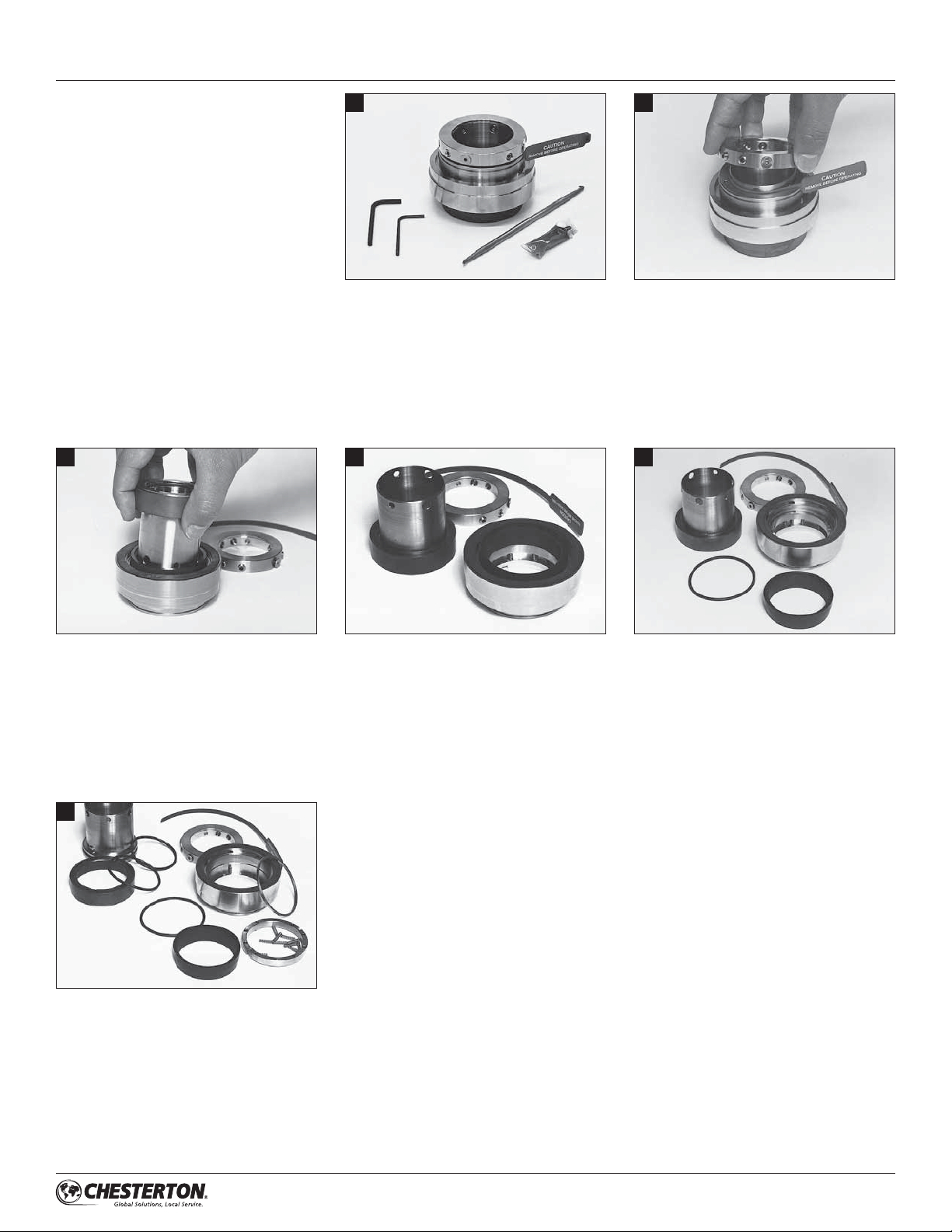
DISASSEMBLY (1-6) – SMALL (1" to 2.5" [25 mm to 60 mm] shaft/sleeve)
For 155 seal, remove the tabs or the 478
or other gland before disassembling the
seal. Remove the tabs by removing the
tab retaining snap ring and pressing the
tabs towards the center of the hub gland
and then sliding them out. To remove
the 478 or other gland just pull the gland
away from the hub gland.
3
1
You will need the hex keys provided with
the seal, and an O-ring extractor or paper
clip to disassemble the seal.
4
2
Place the seal, lock ring side up, on a flat
surface. Back out all the screws from the
sleeve. Remove the lock ring. Remove the
centering strap.
5
While holding the sleeve and gland together,
turn the seal assembly over and lift out
the rotary and the sleeve, separating the
stationary face from the rotary face with your
fingers. Turn the faces in opposite directions
if it becomes difficult to separate them.
6
Remove the back-up washer and
stationary drive with the springs. Remove
the springs from the stationary drive.
Remove the rotary, rotary O-ring and
shaft O-ring from the sleeve.
Place the rotary and the sleeve next to
the gland assembly.
vÌÊÕÌÊÌiÊÃÌ>Ì>ÀÞÊ>`ÊÀiÛiÊÌiÊ
dynamic O-ring.
3
ASSEMBLY (7-14) – SMALL (1" to 2.5" [25 mm to 60 mm] shaft/sleeve)
7
ÕLÀV>ÌiÊÌiÊÃiiÛiÊ°°Ê"À}ÊÜÌÊÌiÊ
silicone grease provided and install it in
ÌiÊÃiiÛiÊ°°Ê}ÀÛi°ÊÕLÀV>ÌiÊÌiÊ
rotary O-ring and install it in the sleeve
O.D. groove.
10
8
Slide the rotary onto the sleeve, aligning
the drive tabs with the rotary slots. Slide
the rotary over the O-ring until the rotary
bottoms out. Check to make sure the
drive tabs are properly engaged.
11
9
Place a spring in each hole in the stationary
drive. A small amount of silicone grease can
be applied to the bottom of each spring.
This will help the springs stay in the holes.
12
Place the hub gland assembly with the
gasket side up, on a flat surface. Align the
slots in the stationary drive with the tabs
in the hub gland. Slide the stationary drive
in until the springs touch the hub gland.
Place the back-up washer in the hub
gland. It will rest on the stationary drive
until the seal is compressed.
13
ÕLÀV>ÌiÊÌiÊ`Þ>VÊ"À}ÊvÀÊÌiÊ
stationary. Slide the O-ring onto the
stationary. Slide the stationary into the
hub gland until it engages the stationary
drive. Be sure to line-up the drive tabs
with the stationary slots.
Turn the assembly over and place with
the lock ring side of the sleeve up, on
a flat surface. Place the lock ring over
the sleeve, lining up the flat head socket
screws with the smaller holes and the cup
point set screws with the larger holes.
Press down on the lock ring and tighten
the flat head socket screws and the cup
point set screws. Check to ensure that
the sleeve is not deformed while tightening
the set screws. Make sure the screws do
not protrude into the sleeve I.D. bore.
Wipe the stationary and rotary faces clean
with a lint free cloth. Place the hub gland,
with the stationary installed, stationary side
up on a flat surface. Place the stuffing box
face gasket in the hub gland. Slide the
sleeve, with the rotary installed, downwards
into the hub gland. Pick up the hub gland
and sleeve and continue to push them
together until the faces contact each other.
14
Press down on the hub gland and push
the centering strap through the slot in
the hub gland. Push the strap in until it
completely surrounds the seal sleeve.
It will pilot between the hub gland, seal
sleeve and lock ring.
4

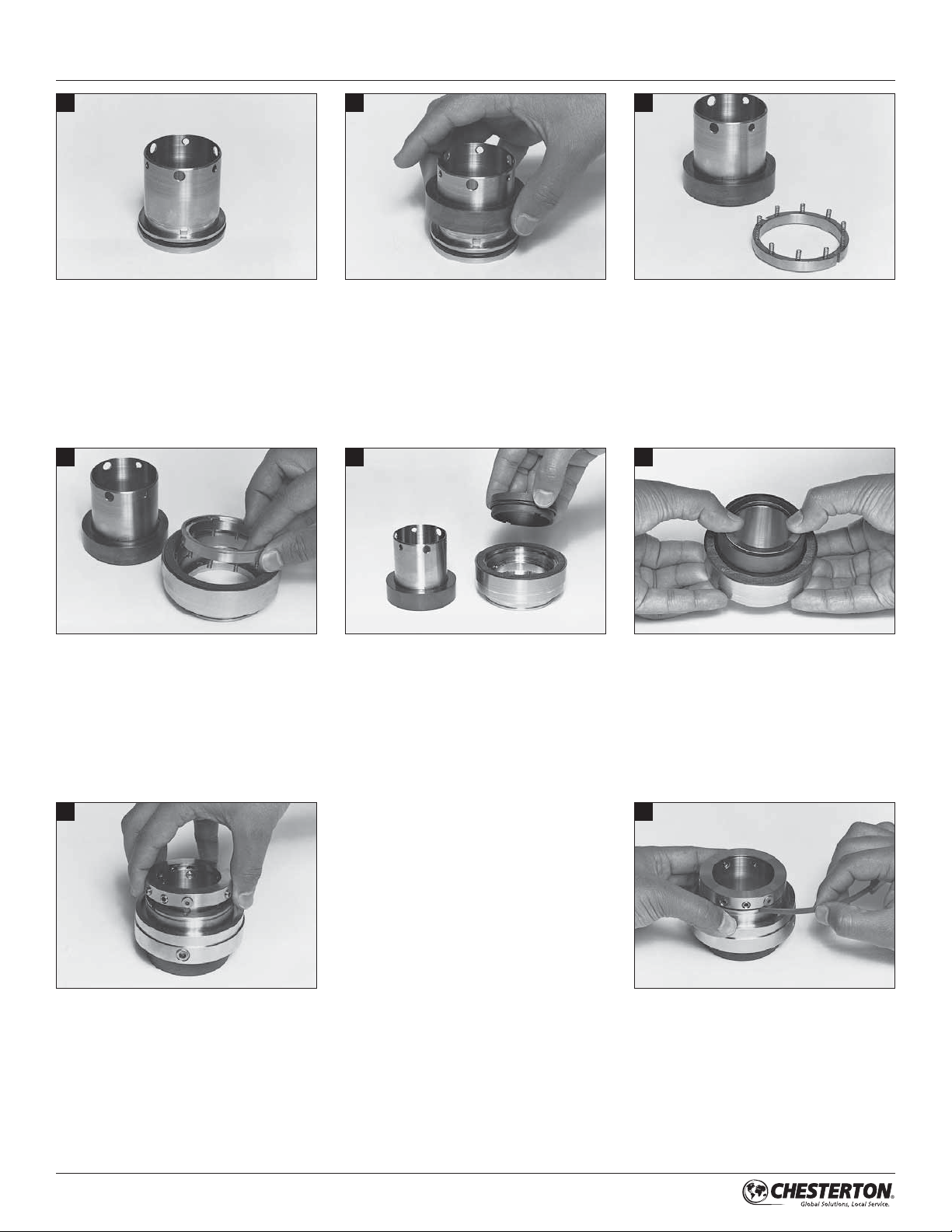
DISASSEMBLY (1-8) – LARGE (larger than 2.5" [60 mm] shaft/sleeve)
1
You will need the hex keys provided with
the seal, and an O-ring extractor or paper
clip to disassemble the seal.
4
2
For 155 large seal, remove the tabs or the
478 or other gland before disassembling
the seal. Remove the tabs by removing the
tab retaining snap ring and pressing the
tabs towards the center of the hub gland
and then sliding them out. To remove the
478 or other gland just pull the gland away
from the hub gland.
5
3
Place the seal, lock ring side up, on a flat
surface. Back out all the screws from the
sleeve. Remove the lock ring. Remove the
centering strap.
6
While holding the sleeve and gland
together, turn the seal assembly over
and lift out the rotary and the sleeve,
separating the stationary face from the
rotary face with your fingers.
7
Remove the stationary and the adapter
together. Separate them and remove the
dynamic O-ring.
Place the rotary and the sleeve next to the
gland assembly.
8
Remove the stationary drive with the
springs. Remove the static O-ring from
inside the hub gland. Remove the springs
from the stationary drive.
Remove the rotary, rotary O-ring and shaft
O-ring from the sleeve.
5

ASSEMBLY (9-19) – LARGE (larger than 2.5" [60 mm] shaft/sleeve)
9
ÕLÀV>ÌiÊÌiÊÃiiÛiÊ°°Ê"À}ÊÜÌÊ
the silicone grease provided and install
ÌÊÊÌiÊÃiiÛiÊ°°Ê}ÀÛi°ÊÕLÀV>ÌiÊÌiÊ
rotary O-ring and install it in the sleeve
O.D. groove.
12
10
Slide the rotary onto the sleeve, aligning the
drive tabs with the rotary slots. Slide the
rotary over the O-ring until the rotary bottoms
out. Check to make sure the drive tabs are
properly engaged.
13
11
Place a spring in each hole in the stationary
drive. A small amount of silicone grease can
be applied to the bottom of each spring.
This will help the springs stay in the holes.
14
Place the hub gland assembly with the
}>ГiМКГ`iКХ«]КК>Кv>МКГХАv>Vi°КХLАV>МiК
the static O-ring and install it in the hub
gland. Align the slots in the stationary drive
with the tabs in the hub gland. Slide the
stationary drive in until the springs touch
the hub gland. Place the back-up washer
in the hub gland.
ÕLÀV>ÌiÊÌiÊ`Þ>VÊ"À}ÊvÀÊÌiÊ
stationary and slide it in the adapter I.D.
groove. Place the stationary face down
on a flat surface and press the adapter
onto the stationary.
Slide the stationary and adapter assembly
into the hub gland until it engages the
stationary drive. Be sure to line-up the drive
tabs with the stationary slots.
6

ASSEMBLY (9-19
) –
LARGE (larger than 2.5" [60 mm] shaft/sleeve)
15
Wipe the stationary and rotary faces clean
with a lint free cloth. Place the hub gland,
with the stationary installed, stationary side
up on a flat surface. Place the stuffing box
face gasket in the hub gland.
18
16
Slide the sleeve, with the rotary installed,
downwards into the hub gland. Pick up
the hub gland and sleeve and continue
to push them together until the faces
contact each other.
19
17
Press down on the hub gland and push the
centering strap through the slot in the hub
gland. Push the strap in until it completely
surrounds the seal sleeve. It will pilot
between the hub gland, seal sleeve and
lock ring.
Turn the assembly over and place with
the lock ring side of the sleeve up, on a flat
surface. Place the lock ring over the sleeve,
lining up the flat head socket screws and
hybrid dog/cup point set screws with the
smaller holes. Also, line up the cup point
set screws with the larger holes. Press
down on the lock ring and tighten the flat
head socket screws, hybrid dog/cup point
set screws and the cup point set screws.
Check to ensure that the sleeve is not
deformed while tightening the set screws.
Make sure the screws do not protrude
into the sleeve I.D. bore.
Replace the tabs by pressing the tabs
toward the center of the hub gland and
then sliding them in. Reinstall the tab
retaining snap ring. The assembly is
now complete.
7

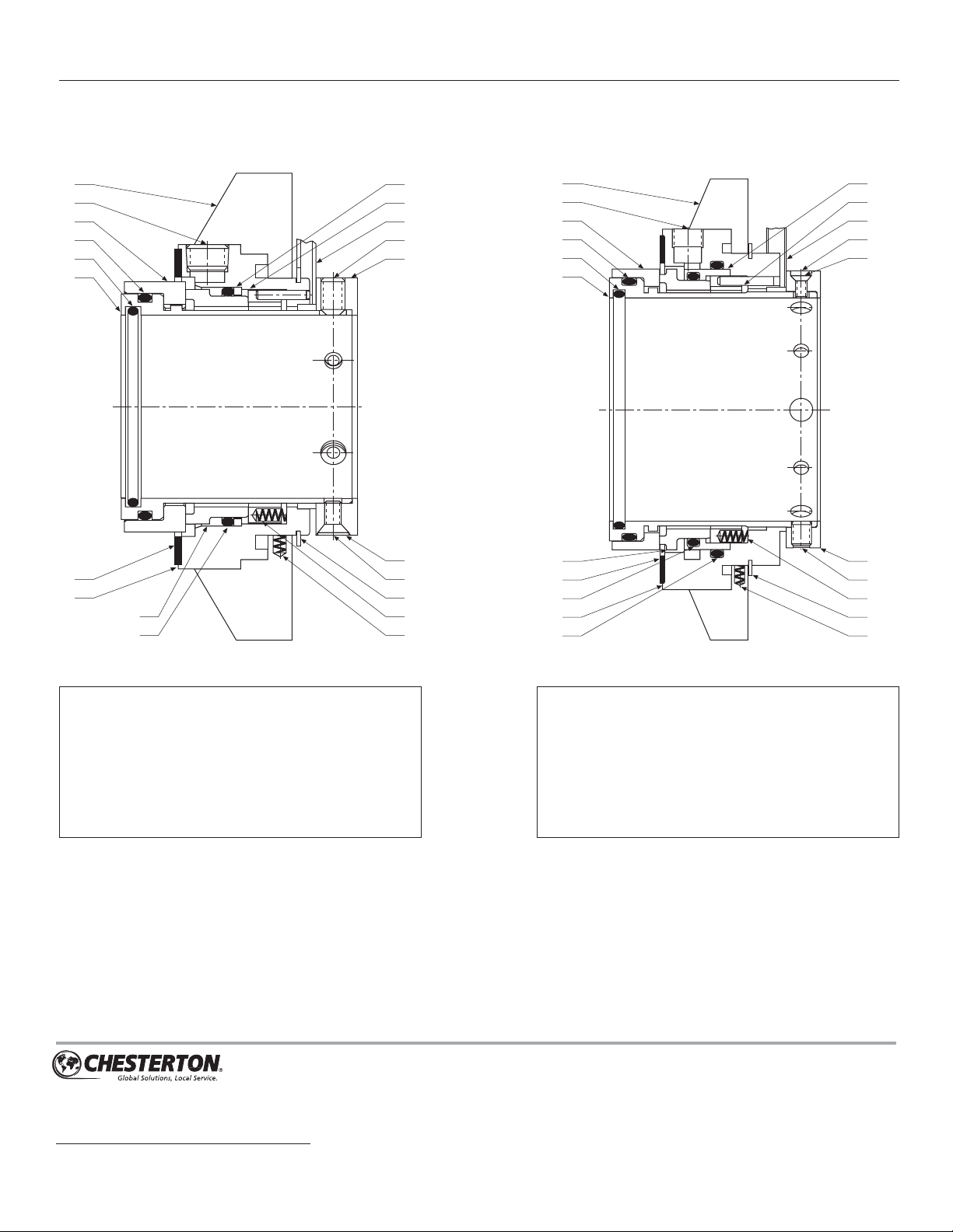
DIMENSIONAL DATA (DRAWINGS) – SMALL
E MIN
F
V
UTS
D A
N M
1/16" Spring Gap
(Typical)
K
L P RC
J
478 GLAND TABS
H
CAUTION:
REMOVE BEFORE OPERATING
G MIN
B MAX
CAUTION:
REMOVE BEFORE OPERATING
G MIN
B MAX
8

DIMENSIONAL DATA (INCH) – SMALL
STUFFING
SHAFT BOX BORE
SIZE DASH B MAX B MAX C C E
A SIZE TABS 478 MIN MAX D MIN F
1.000 8 4.65 4.24 1.75 2.00 1.69 0.63 1.89
1.125 9 4.69 4.24 1.88 2.03 1.82 0.63 1.89
1.250 10 4.90 4.49 2.00 2.26 1.94 0.63 1.89
1.375 11 5.04 4.99 2.13 2.42 2.07 0.63 1.89
1.500 12 5.23 4.99 2.25 2.62 2.19 0.63 1.89
1.625 13 5.29 4.99 2.38 2.68 2.32 0.63 1.89
1.750 14 5.41 5.49 2.50 2.80 2.44 0.63 1.89
1.875 15 5.53 5.49 2.63 2.93 2.57 0.63 1.89
2.000 16 5.74 5.99 2.75 3.18 2.69 0.63 1.89
2.125 17 6.04 5.99 2.88 3.43 2.82 0.63 1.89
2.250 18 6.14 6.24 3.00 3.55 2.94 0.63 1.89
2.375 19 6.29 6.24 3.13 3.59 3.07 0.63 1.89
2.500 20 6.41 6.49 3.25 3.80 3.19 0.63 1.89
G MIN G MIN
TABS 478
3/8" 1/2" 5/8" 3/8" 1/2" 5/8"
BOLTS BOLTS BOLTS BOLTS BOLTS BOLTS
2.88 3.01 3.13 2.90 – –
2.92 3.05 3.17 2.90 – –
3.13 3.26 3.38 3.21 – –
3.27 3.40 3.52 3.52 – –
3.46 3.59 3.71 3.52 – –
3.52 3.65 3.77 3.51 3.63 –
3.64 3.77 3.89 3.74 3.86 –
3.76 3.89 4.01 3.90 4.02 –
3.97 4.10 4.22 4.15 4.27 –
4.27 4.40 4.52 4.53 4.66 4.78
4.38 4.51 4.63 4.56 4.69 4.81
4.52 4.65 4.77 4.56 4.69 4.81
4.65 4.78 4.90 4.79 4.92 5.04
DIMENSIONAL DATA (METRIC) – SMALL
STUFFING
SHAFT BOX BORE
SIZE B MAX B MAX C C E
A TABS 478 MIN MAX D MIN F
25 118 108 44 51 43 16 48
28 118 108 47 52 46 16 48
30 124 111 49 57 48 16 48
32 124 114 51 58 50 16 48
33 124 114 52 59 51 16 48
35 128 127 54 62 52 16 48
38 133 127 57 67 56 16 48
40 134 127 59 68 58 16 48
43 134 127 62 69 61 16 48
45 140 139 64 73 63 16 48
48 139 139 67 74 66 16 48
50 145 139 69 78 68 16 48
55 150 158 74 83 73 16 48
60 160 158 79 91 78 16 48
G MIN G MIN
TABS 478
8 mm 10 mm 12 mm 8 mm 10 mm 12 mm
BOLTS BOLTS BOLTS BOLTS BOLTS BOLTS
70 72 74 71 73 –
70 72 74 71 73 –
76 78 80 77 79 –
77 79 81 78 80 –
76 78 80 78 80 –
80 82 84 86 88 –
85 87 89 86 88 –
86 88 90 86 88 90
86 88 90 86 88 90
92 94 96 92 94 96
91 93 95 92 94 96
97 99 101 96 98 100
102 104 106 112 114 116
112 114 116 113 115 117
NPT
478 SIZE
H J K L M N P R S T U GLAND V
0.44 0.93 0.37 1.76 1.58 0.47 2.25 2.45 120 124 126 9 1/8"
0.44 0.93 0.37 1.89 1.58 0.47 2.25 2.48 122 126 128 9 1/8"
0.44 0.93 0.37 2.01 1.58 0.47 2.43 2.70 124 128 130 11 1/8"
0.44 0.93 0.37 2.14 1.58 0.47 2.75 2.84 126 130 132 12 1/8"
0.44 0.93 0.37 2.26 1.58 0.47 2.75 3.03 128 132 134 12 1/8"
0.58 0.93 0.37 2.39 1.58 0.47 2.87 3.08 130 134 136 13 1/8"
0.58 0.93 0.37 2.51 1.58 0.47 3.12 3.21 132 136 138 14 1/8"
0.58 0.93 0.37 2.64 1.58 0.47 3.25 3.33 134 138 140 15 1/8"
0.58 0.93 0.37 2.76 1.58 0.47 3.50 3.54 136 140 142 16 1/8"
0.69 0.93 0.37 2.89 1.58 0.47 3.75 3.84 138 142 144 18 1/8"
0.69 0.93 0.37 3.01 1.58 0.47 3.87 3.94 140 144 146 19 1/8"
0.69 0.93 0.37 3.14 1.58 0.47 3.90 4.08 142 146 148 19 1/8"
0.69 0.93 0.37 3.26 1.58 0.47 4.12 4.21 144 148 150 20 1/8"
NPT
478 SIZE
H J K L M N P R S T U GLAND V
11 24 9 44 40 12 57 62 120 124 126 9 1/8"
11 24 9 47 40 12 57 62 121 126 128 9 1/8"
11 24 9 49 40 12 60 68 123 127 129 10 1/8"
11 24 9 51 40 12 62 69 124 128 130 11 1/8"
11 24 9 52 40 12 62 69 125 129 131 11 1/8"
11 24 9 54 40 12 70 72 126 130 132 12 1/8"
11 24 9 57 40 12 70 77 128 132 134 12 1/8"
15 24 9 59 40 12 73 78 129 134 135 13 1/8”
15 24 9 62 40 12 73 78 131 135 137 13 1/8"
15 24 9 64 40 12 79 84 132 136 138 14 1/8"
15 24 9 67 40 12 79 84 134 139 140 14 1/8"
15 24 9 69 40 12 82 89 136 140 142 15 1/8"
17 24 9 74 40 12 94 94 139 143 145 18 1/8"
17 24 9 80 40 12 99 104 142 146 148 19 1/8"
KEY (drawings & charts)
A – Shaft Size
B – Maximum Gland Tab Diameter
C – Stuffing Box Inside Diameter
D – Seal Diameter in Stuffing Box
E – Minimum Stuffing Box Depth
Ê qÊ "ÕÌL>À`Ê-i>Êi}Ì
G – Minimum Bolt Circle by Bolt Size
H – Slot Width
J – Hub Gland Flange Width
K – Hub Gland Sot Width
Ê qÊ VÊ,}Ê>iÌiÀ
M – Distance from Stuffing Box Face to Set Screws
N – Distance from Stuffing Box Face to Shaft O-Ring
P – Hub Gland Slot Diameter
R – Hub Gland Diameter
S – Shaft O-Ring
T – Rotary O-Ring
U – Stationary O-Ring
V – NPT Size
9

DIMENSIONAL DATA (DRAWINGS) – LARGE & OVERSIZE
LARGE
E
MIN
D A
N M
F
W
3/32" Spring Gap
(Typical)
U VTS
J
TABS
CAUTION:
REMOVE BEFORE OPERATING
L RC
B MAX
G MIN
K
OVERSIZE – SMALL
(1.13" to 2.50" shaft/sleeve)
E
MIN
D A
N M
F
W
UTS
OVERSIZE – LARGE
(2.63" to 4.75" shaft/sleeve)
E MIN
L RC
D A
N M
F
W
U VTS
L RC
10
1/16" Spring Gap
J
(Typical)
K
J
K
3/32" Spring Gap
(Typical)

DIMENSIONAL DATA (INCH) – LARGE
STUFFING
SHAFT BOX BORE G MIN
SIZE DASH B C C E 1/2" 5/8" 3/4"
A SIZE MAX MIN MAX D MIN F BOLTS BOLTS BOLTS
2.625 21 7.63 3.63 4.00 3.54 0.88 2.50 5.35 5.48 5.60
2.750 22 7.76 3.75 4.13 3.67 0.88 2.50 5.48 5.60 5.73
2.875 23 7.88 3.88 4.25 3.79 0.88 2.50 5.60 5.73 5.85
3.000 24 8.01 4.00 4.44 3.92 0.88 2.50 5.73 5.85 5.98
3.125 25 8.13 4.13 4.55 4.04 0.88 2.50 5.85 5.98 6.10
3.250 26 8.26 4.25 4.69 4.17 0.88 2.50 5.98 6.10 6.23
3.375 27 8.38 4.38 4.80 4.29 0.88 2.50 6.10 6.23 6.35
3.500 28 8.51 4.50 4.94 4.42 0.88 2.50 6.23 6.35 6.48
3.625 29 8.63 4.63 5.05 4.54 0.88 2.50 6.35 6.48 6.60
3.750 30 8.76 4.75 5.14 4.67 0.88 2.50 6.48 6.60 6.73
3.875 31 8.88 4.88 5.26 4.79 0.88 2.50 6.60 6.73 6.85
4.000 32 9.01 5.00 5.44 4.92 0.88 2.50 6.73 6.85 6.98
4.125 33 9.13 5.13 5.55 5.04 0.88 2.50 6.85 6.98 7.10
4.250 34 9.18 5.25 5.69 5.17 0.88 2.50 6.89 7.02 7.14
4.375 35 9.30 5.38 5.81 5.29 0.88 2.50 7.02 7.14 7.27
4.500 36 9.43 5.50 5.94 5.42 0.88 2.50 7.14 7.27 7.39
4.625 37 9.56 5.63 6.06 5.54 0.88 2.50 7.27 7.39 7.52
4.750 38 9.76 5.75 6.22 5.67 0.88 2.50 7.47 7.60 7.72
DIMENSIONAL DATA (METRIC) – LARGE
STUFFING
SHAFT BOX BORE G MIN
SIZE B C C E 10 mm 12 mm 16 mm
A MAX MIN MAX D MIN F BOLTS BOLTS BOLTS
65 194 92 102 90 22 64 132 134 138
70 197 95 105 93 22 64 135 137 141
75 203 100 113 99 22 64 141 143 147
80 207 105 116 103 22 64 144 146 150
85 213 110 122 109 22 64 151 153 157
90 216 115 125 113 22 64 154 156 160
95 222 120 131 118 22 64 160 162 166
100 229 127 138 125 22 64 167 169 173
110 236 136 148 134 22 64 174 176 180
120 248 145 158 144 22 64 186 188 192
O-RINGS NPT
SIZE
J K L M N R S T U V W
1.08 1.33 3.49 2.22 0.68 4.79 231 234 236 239 1/4"
1.08 1.33 3.61 2.22 0.68 4.92 232 235 237 240 1/4"
1.08 1.33 3.74 2.22 0.68 5.04 233 236 238 241 1/4"
1.08 1.33 3.86 2.22 0.68 5.17 234 237 239 242 1/4"
1.08 1.33 3.99 2.22 0.68 5.29 235 238 240 243 1/4"
1.08 1.33 4.11 2.22 0.68 5.42 236 239 241 244 1/4'
1.08 1.33 4.24 2.22 0.68 5.54 237 240 242 245 1/4"
1.08 1.33 4.36 2.22 0.68 5.67 238 241 243 246 1/4"
1.08 1.33 4.49 2.22 0.68 5.79 239 242 244 247 1/4"
1.08 1.33 4.61 2.22 0.68 5.92 240 243 245 248 1/4"
1.08 1.33 4.74 2.22 0.68 6.04 241 244 246 249 1/4"
1.08 1.33 4.86 2.22 0.68 6.17 242 245 247 250 1/4"
1.08 1.33 4.99 2.22 0.68 6.29 243 246 248 251 1/4"
1.08 1.33 5.11 2.22 0.68 6.33 244 247 249 252 1/4"
1.08 1.33 5.24 2.22 0.68 6.46 245 248 250 253 1/4"
1.08 1.33 5.36 2.22 0.68 6.58 246 249 251 254 1/4”
1.08 1.33 5.49 2.22 0.68 6.71 247 250 252 255 1/4"
1.08 1.33 5.61 2.22 0.68 6.91 248 251 253 256 1/4"
O-RINGS NPT
SIZE
J K L M N R S T U V W
34 89 56 17 122 231 234 236 239 1/4"
27
27 34 92 56 17 125 232 235 237 240 1/4"
27 34 98 56 17 131 234 237 239 242 1/4"
27 34 102 56 17 134 236 238 240 243 1/4"
27 34 108 56 17 141 237 240 242 245 1/4"
27 34 112 56 17 144 239 241 243 246 1/4"
27 34 117 56 17 150 240 243 245 248 1/4"
27 34 123 56 17 157 242 245 247 250 1/4"
27 34 133 56 17 164 245 248 250 253 1/4"
27 34 142 56 17 176 248 251 253 256 1/4"
DIMENSIONAL DATA (INCH) – OVERSIZE
STUFFING
SHAFT BOX BORE G MIN
SIZE DASH B C C E 3/8" 1/2" 5/8" 3/4" 7/8"
A SIZE MAX MIN MAX D MIN F BOLTS BOLTS BOLTS BOLTS BOLTS
1.125 9 5.29 2.50 2.75 1.82 0.63 1.89 3.59 3.72 3.84 – –
1.375 11 5.57 2.68 3.00 2.07 0.63 1.89 3.86 3.99 4.11 – –
1.750 14 6.64 3.37 3.75 2.44 0.63 1.89 4.93 5.06 5.18 – –
1.875 15 6.58 3.42 3.81 2.57 0.63 1.89 4.88 5.01 5.13 – –
2.125 17 7.31 3.75 4.25 2.82 0.63 1.89 5.60 5.73 5.85 – –
2.500 20 8.14 4.37 4.75 3.19 0.63 1.89 6.43 6.56 6.68 – –
2.625 21 8.04 4.38 4.78 3.54 0.88 2.50 – 5.83 5.96 6.08 6.21
2.750 22 8.04 4.28 4.78 3.67 0.88 2.50 – 5.83 5.96 6.08 6.21
3.000 24 8.65 4.75 5.39 3.92 0.88 2.50 – 6.44 6.57 6.69 6.82
3.375 27 8.54 4.78 5.27 4.29 0.88 2.50 – 6.33 6.46 6.58 6.71
3.750 30 9.63 5.78 6.40 4.67 0.88 2.50 – 7.41 7.54 7.66 7.79
4.125 33 9.54 5.78 6.27 5.04 0.88 2.50 – 7.33 7.46 7.58 7.71
4.750 38 11.25 7.03 7.65 5.67 0.88 2.50 – 9.04 9.17 9.29 9.42
KEY (drawings & charts)
A – Shaft Size
B – Maximum Gland Tab Diameter
C – Stuffing Box Inside Diameter
D – Seal Diameter in Stuffing Box
E – Minimum Stuffing Box Depth
Ê qÊ "ÕÌL>À`Ê-i>Êi}Ì
G – Minimum Bolt Circle by Bolt Size
J – Hub Gland Flange Width
K – Distance from Stuffing Box Face to Back of Tab
Ê qÊ VÊ,}Ê>iÌiÀ
M – Distance from Stuffing Box Face to Set Screws
N – Distance from Stuffing Box Face to Shaft O-Ring
R – Hub Gland Diameter
S – Shaft O-Ring
T – Rotary O-Ring
U – Stationary O-Ring
V – Gland O-Ring
(applies only to large size and large oversize seal)
W – NPT Size
O-RINGS NPT
SIZE
J K L M N R S T U V W
0.93 1.18 1.89 1.58 0.47 3.15 122 126 128 – 1/4"
0.93 1.18 2.14 1.58 0.47 3.43 126 130 132 – 1/4"
0.93 1.18 2.51 1.58 0.47 4.49 132 136 138 – 1/4"
0.93 1.18 2.64 1.58 0.47 4.44 134 138 140 – 1/4"
0.93 1.18 2.89 1.58 0.47 5.17 138 142 144 – 1/4"
0.93 1.18 3.26 1.58 0.47 6.00 144 148 150 – 1/4”
1.08 1.33 3.49 2.22 0.68 5.27 231 234 236 239 1/4"
1.08 1.33 3.61 2.22 0.68 5.27 232 235 237 240 1/4"
1.08 1.33 3.86 2.22 0.68 5.88 234 237 239 242 1/4"
1.08 1.33 4.24 2.22 0.68 5.77 237 240 242 245 1/4"
1.08 1.33 4.61 2.22 0.68 6.86 240 243 245 248 1/4"
1.08 1.33 4.99 2.22 0.68 6.77 243 246 248 251 1/4"
1.08 1.33 5.61 2.22 0.68 8.48 248 251 253 256 1/4"
11
PARTS IDENTIFICATION
(1" to 2.5" [25 mm to 60 mm] shaft/sleeve)
1
2
3
4
4
5
6
7
8
4
9
10
11
12
13
14
15
16
17
18
1
2
3
4
4
5
6
7
4
8
4
(larger than 2.5" [60 mm] shaft/sleeve)
SMALL
LARGE
9
10
11
12
13
14
15
16
17
18
KEY
1 – Bolt Tab
2 – Pipe Plug
3 – Rotary Seal Ring
4 – O-Ring
5 – Sleeve
6 – Gasket
7 – Hub Gland Assembly
8 – Stationary Seal Ring
9 – Back-up Washer
155 is a trademark of A.W. Chesterton Company.
860 Salem Street
Groveland, MA 01834 USA
Telephone: 781-438 -7000 Fax: 978-469- 6528
www.chesterton.com
© A.W.Chesterton Company, 2014. All rights reserved.
® Registered trademark owned and licensed by
A.W. Chesterton Company in USA and other countries.
10 – Stationary Drive
11 – Centering Strap
12 – Cup Point Set Screw
£ÎÊqÊ VÊ,}
14 – Dot
15 – Flat HD Socket Screw
16 – Snap Ring
17 – Spring
18 – Bolt Tab Spring
KEY
1 – Bolt Tab
2 – Pipe Plug
3 – Rotary Seal Ring
4 – O-Ring
5 – Sleeve
6 – Stationary Seal Ring
7 – Gasket
8 – Hub Gland Assembly
9 – Adapter
Chesterton ISO certificates available on www.chesterton.com/corporate/iso
FORM NO. 071379 REV. 5 PRINTED IN USA 04/14
10 – Stationary Drive
11 – Centering Strap
12 – Flat HD Socket Screw
13 – Dot
£{ÊqÊ VÊ,}
15 – Cup Point Set Screw
1/4 Dog Point Set Screw (not shown)
16 – Spring
17 – Snap Ring
18 – Bolt Tab Spring
 Loading...