

Page 1
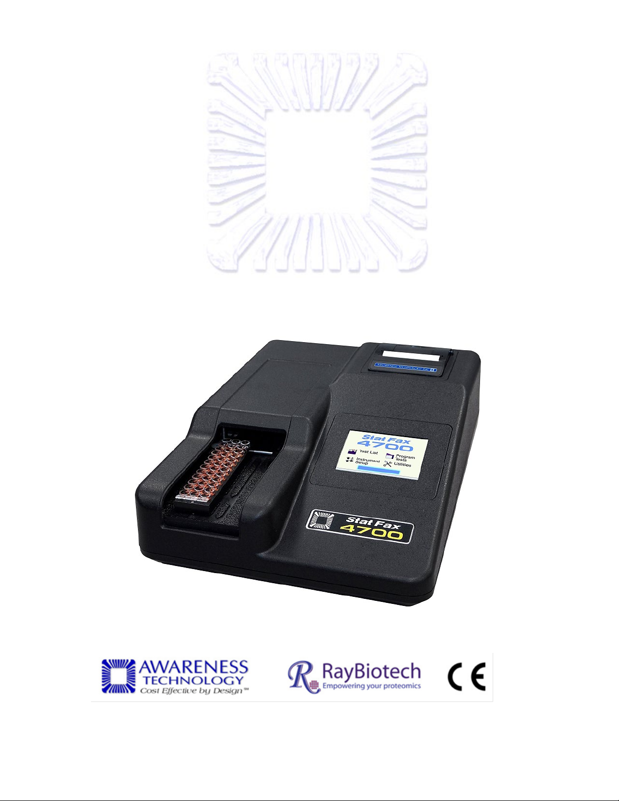
Stat Fax 4700
®
MICROSTRIP READER
OPPEE
O
RAATT
R
O
O
R
R
’
SS M
’
MAA
N
UAALL
N
U
© Awareness Technology Inc. 2010 Doc. 4700 Revised 2018 Rev. G
Page 2

Page 3

TABLE OF CONTENTS
1. Introduction ...................................................................................................... 1
1.1 Applications .............................................................................................................................. 1
1.1.1 Intended Use ..................................................................................................................... 1
1.1.2 Summary of the Instrument ............................................................................................... 1
1.1.3 Principles of Operation ...................................................................................................... 2
1.2 Warning Markings Inscriptions d’avertissement ..................................................................... 3
1.2.1 Safety Symbols Le Symboles de Sûreté ........................................................................... 3
1.2.2 Safety Terms Terminologie de Sûreté .............................................................................. 3
1.3 Safety Precautions ................................................................................................................... 4
1.4 Specifications ........................................................................................................................... 6
1.5 Installation ................................................................................................................................ 8
1.5.1 General .............................................................................................................................. 8
1.5.2 Installation/Preparation...................................................................................................... 9
1.5.3 Touch Screen Description ............................................................................................... 10
1.5.4 Load Paper ...................................................................................................................... 11
1.6 Parts and Controls ................................................................................................................. 12
1.6.1 Strip Carrier Loading and Positioning ............................................................................. 13
1.6.2 Auto-Track ....................................................................................................................... 14
1.7 Checkout Procedure .............................................................................................................. 17
2. Operating Procedures ................................................................................... 18
2.1 Operating Precautions ........................................................................................................... 18
2.2 General Selections ................................................................................................................. 18
2.3 Main Display Menu Options ................................................................................................... 19
2.3.1 Run Test .......................................................................................................................... 20
2.3.2 Settings ........................................................................................................................... 21
2.3.2.1 External Output ....................................................................................................... 22
2.3.2.2 Mouse Connection .................................................................................................. 22
2.3.3 Manage Tests .................................................................................................................. 23
2.3.4 Utilities ............................................................................................................................. 24
2.4 General Operation ................................................................................................................. 25
2.4.1 Bichromatic Differential Operation .................................................................................. 25
2.4.2 Unit of Measurement Codes (Unit Code) ........................................................................ 26
2.5 Modes of Operation ............................................................................................................... 27
2.5.1 Absorbance Mode ........................................................................................................... 29
2.5.1.1 Filter Selection ........................................................................................................ 29
2.5.1.2 Offset Absorbance .................................................................................................. 30
2.5.1.3 Blank ....................................................................................................................... 30
2.5.1.4 Lamp Saver ............................................................................................................ 31
2.5.2 Factor Mode .................................................................................................................... 31
2.5.3 Single Standard Mode ..................................................................................................... 34
2.5.4 Multi-Point Modes (Point-to-Point, Regression and Cubic Spline) ................................. 36
2.5.5 Cut Off Mode ................................................................................................................... 42
3. Cleaning and Maintenance ............................................................................ 48
3.1 Cleaning ................................................................................................................................. 48
3.1.1 Exterior ............................................................................................................................ 48
3.2 Maintenance........................................................................................................................... 48
3.2.1 Calibration and Linearity.................................................................................................. 48
3.2.2 Storage ............................................................................................................................ 49
Page 4

4. Troubleshooting ............................................................................................. 50
4.1 Messages and Flags .............................................................................................................. 50
4.2 Error Messages ...................................................................................................................... 53
5. References...................................................................................................... 55
6. Optional Accessories .................................................................................... 55
6.1 Thermal Printer Paper ............................................................................................................ 55
6.2 Dri-Dye® Check Strips ........................................................................................................... 55
7. Information ..................................................................................................... 56
8. Appendix A – SF_Capture ............................................................................. 57
9. Appendix B - Installing new software .......................................................... 58
10. Appendix C – Touchpad Alignment ........................................................... 58
Page 5

1. Introduction
1.1 Applications
1.1.1 Intended Use
®
The Stat Fax
system designed to read and calculate the results of assays, which are read in microtiter
strips or break apart wells.
The Stat Fax
open system with selectable strip formatting, alphanumeric test naming, automatic
interpretation options, duplicate well options, curve plotting and editing, and flags and error
messages.
It is a general purpose instrument intended to be used by trained laboratory professionals
who are capable of selecting the appropriate features and options for each specific clinical
application. Contact your company’s instrument service provider to arrange for training if the
information in this manual is not sufficient.
1.1.2 Summary of the Instrument
The Stat Fax
is also capable of monochromatic reading using four standard filters (405, 450, 492, and 630
nm) Special models are available with either six VIS (405, 450, 492, 545, 600, and 630 nm)
or six UV (340, 405, 450, 492, 545, and 630 nm). Alternate filters are available from 340 to
700 nm.
4700 is a compact, microprocessor-controlled, multi-purpose photometer
®
4700 may be used for in-vitro diagnostic testing. It is a user-programmable
FOR IN-VITRO DIAGNOSTIC USE
POUR L'USAGE DIAGNOSTIQUE IN VITRO
®
4700 is specifically designed for bichromatic absorbance reading, however it
This instrument is programmed with many keypad-selectable general purpose programs.
Each mode is self-prompting, to reduce error and simplify operation. The general purpose
programs include relative light unit, multi-point linear and log-logit regressions, and point-topoint connections.
These calculation modes have been selected to facilitate the performance of Elisa
immunoassays.
Convenience features include automatic blanking options, the ability to indicate the locations
of positive and negative controls, and to enter control acceptance criteria for automatic
comparisons, to select positive and negative interpretations based on concentration value,
and to edit out discrepant duplicates with automatic re-calculation. In addition, userprogrammable memory allows the operator to store test protocols, recall tests by number,
and delete unwanted tests from a user-generated test menu. Instructions for each of these
modes and convenience features are provided in this manual.
Besides quick, accurate, and reproducible results, the instrument offers maintenance-free
and easy operation, versatility, and economy. A stable, factory-calibrated durable design
assures the reliability of the instrument.
Stat Fax® 4700 Operator’s Manual Doc. 4700 Rev. G 1
Page 6

Summary of the Instrument (Continued)
The Auto-Track feature enables all three strips to be read automatically, rather than having
to read each strip individually. The Stat Fax
®
4700 uses a specialized strip carrier. Be sure
to use only this carrier. Starting from Position A (home position), the Auto-track feature
transports the carrier such that all of the wells in all strips in the carrier are read; user is
prompted to place the carrier into position by changing the background color and emitting a
sound.
• Features
Store up to 120 tests Starting from the home position, the Auto-track feature transports
the carrier such that all of the wells in all strips in the carrier are read; sounds and
colorful displays guide the user. Transmit and capture data via USB to PC connectivity
using SF_Capture
software (see External Output section).
Pre-programmed Modes
In addition to reading absorbance, this instrument can be programmed to calculate
concentrations based on stored formulas using absorbance readings of one or more
calibrators. The basic calculations are permanently stored in memory and include
several single and multi-point equations. Provisions are made in certain cases for
reading specimens in duplicate and/or using the mean reading in calculations. Each
calculation mode is described in detail in Section 2.5-Modes of Operation. The following
calculation modes are offered: Single point calibration by standard or factor, multi-point
calibration with point-to-point curve fit, linear regressions with log, linear, and log-logit
selections, cubic spline and cutoff mode selections.
User-programmable Memory
The instrument’s software allows the operator to create, edit and store a menu of assay
programs. Standard curves are also stored in this memory. Test protocols remain
stored until either changed or deleted by the user.
1.1.3 Principles of Operation
The strip carrier precisely positions each well into the optical path for reading. Light energy
from a lamp is focused by an integral lens, directed through an aperture, and then passed
vertically through the sample. A wheel below the sample positions the filters so that
readings can be taken very quickly at both the operating and differential wavelengths.
(Using bichromatic differential absorbance values improves precision by correcting for
optical imperfections in the plastic wells and removes the effects of meniscus and turbidity.)
A photo detector converts transmitted light energy into electrical signals, which are amplified
and interpreted.
2 Stat Fax® 4700 Operator’s Manual Doc. 4700 Rev. G
Page 7

1.2 Warning Markings Inscriptions d’avertissement
Risk of Shock
Risque de Choc
(Earth) Terminal
Prise de Terre
Refer to Manual
Se Rapportent a Manuel
Risk of Infection
Risque d’infection
These terms may appear on the product: Les marques sur le produit:
DANGER”
CAUTION statements identify conditions or practices that could result
autre propriété.
BIOHAZARDS are biological agents that can cause disease in
agents.
1.2.1 Safety Symbols Le Symboles de Sûreté
Symbols that may appear on the product:
Les symboles de sûreté peuvent apparaitre sur le produit:
WARNING
AVERTISSEMENT
Protective Ground
La Terre Electrique
1.2.2 Safety Terms Terminologie de Sûreté
These terms may appear in this manual: Les marques dans l’opérateur manuel:
DANGER
DANGER Le “de marque:
WARNING
AVERTISSEMENT! Le “de
marque: WARNING”
CAUTION
L’ATTENTION “Le de marque:
CAUTION”
Indicates an injury immediately accessible as you read this marking
Indique le risque immédiat de dommages (assessible tandis que vous
lisez la marque)
WARNING statements identify conditions or practices that could
result in injury or loss of life. WARNING indicates an injury hazard not
immediately accessible as you read this marking.
Ces rapports identifient les conditions ou les pratiques qui pourraient
avoir comme conséquence les dommages ou les pertes humaines.
in damage to this product or other property.
Ces rapports identifient les conditions ou les pratiques qui pourraient
avoir comme conséquence les dommages a ce produit ou a toute
CAUTION
L’ATTENTION
BIOHAZARD
BIOHAZARD
BIOHAZARD
Stat Fax® 4700 Operator’s Manual Doc. 4700 Rev. G 3
humans. Lab workers handling potentially infectious materials must
use universal precautions to reduce the risk of exposure to these
Page 8

1.3 Safety Precautions
below.
Refer any questions to your instrument service provider.
so may void the warranty.
this instrument.
Instructions
manual, or the protection provided by the instrument may be impaired.
the country of use.
making connections to the instrument.
be free of vibrations.
(1/2”).
Do Not Operate Without
Protective Covers
WARNING: Do not operate this instrument with covers and panels removed.
Avoid Exposed Circuitry
WARNING: Do not touch exposed connections and components when power
is present.
Avoid Excessive Dust
Do not operate in an area with excessive dust.
To assure operator safety and prolong the life of your instrument, carefully follow all instructions outlined
Read Instructions Take time to read this manual carefully before using this instrument. Review
the following safety precautions to avoid injury and prevent damage to this
instrument or any products connected to it. To avoid potential hazards, use
this instrument only as specified. For best results, familiarize yourself with the
instrument and its capabilities before attempting any clinical diagnostic tests.
Servicing There are no user-serviceable parts inside the instrument. Refer servicing to
qualified service personnel. Use only factory-authorized parts. Failure to do
Wear Protective Apparel Many diagnostic assays utilize materials that are potential biohazards.
WARNING: Always wear protective apparel and eye protection while using
Follow Operating
Use Proper Power Cord WARNING: Use only the power cord specified for this product and certified for
Observe All Terminal
Ratings
Install as Directed The instrument should be installed on a sturdy, level surface capable of safely
Provide Proper
Ventilation
WARNING: Do not use this instrument in a manner not specified by the
WARNING: To avoid fire or shock hazard, observe all ratings and markings on
the instrument. Consult this manual for further ratings information before
supporting the instrument’s weight 5 lbs (2.3kg). The mounting surface should
Refer to the installation instructions for details on installing the product so it
has proper ventilation. The instrument should be surrounded by the following
clearances: 8cm (3”) around perimeter of unit, 8cm on top, and 1.27cm bottom
4 Stat Fax® 4700 Operator’s Manual Doc. 4700 Rev. G
Page 9
Wet/Damp Conditions
Safety Precautions (Continued)
Do Not Operate With
Suspected Failures
Do Not Operate in
WARNING: If you suspect there is damage to this instrument, have it
inspected by a qualified service person.
WARNING: Do not operate instrument in wet/damp conditions.
Do Not Operate In An
Explosive Atmosphere
Operating Precautions Be sure to run a sufficient number of controls in each assay. If controls are not
Keep Instrument
Surfaces Clean and Dry
WARNING: Do not operate instrument in an explosive atmosphere.
within their acceptable limits, disregard test results.
CAUTION: Solvents such as acetone or paint thinner will damage the
instrument.
• Do not use solvents to clean the unit. Avoid abrasive cleaners; the display
overlay is liquid-resistant, but easily scratched.
• Clean the exterior of the instrument with a soft cloth using plain water. If
needed, a mild all-purpose or nonabrasive cleaner may be used.
• Use as a disinfectant a 10% solution of chlorine bleach (5.25% Sodium
Hypochlorite) or 70% isopropyl alcohol
• Take special care not to spill liquid inside the instrument
CAUTION! L’ATTENTION!
WARNING: If any materials are overturned during operation, immediately set the
power switch to OFF. This material should be treated as potentially biohazardous.
Appropriate cleanup and disposal of biohazardous waste should be used.
Avertissement! Lors du fonctionnement, si on renverse des matériaux, coupez
immédiatement le courant. Placez le commutateur électrique a AU LOIN(0).
Traitez le matériel comme biohazardous, utilisant approprie nettoient et des
méthodes de disposition.
Stat Fax® 4700 Operator’s Manual Doc. 4700 Rev. G 5
Page 10

1.4 Specifications
Photometric
Linear Measurement Range: ............ 0.00 to 3.0 Absorbance Units (A)
Photometric Accuracy: ..................... +/- (1% +/- 0.010) 0.0 through 1.5 ABS
.......................................................... +/- (2% +/- 0.010) 1.5 through 3.0 ABS
Stability: ............................................ Drift of no more than 0.005A in 8 hours bichromatic
Light Source: .................................... Tungsten-Xenon lamp with lamp saver feature
Standard Wavelengths: .................... Standard: 405, 450, 492, and 630nm Six Filter VIS: 405,
450, 492, 545, 600, and 630nm.Six Filter UV: 340, 405,
450, 492, 545, and 630nm
Filter Type: ........................................ IAD hardcoat interference, 10nm half bandpass
Carrier Format: ................................. Strip carrier can hold three break apart 12-well strips or
three 8-well
Vessel: ............................................ Single, or break apart and non-break apart strips up to 12
wells long, 3 strip loading capacity. 1 – 36 well loading
capacity. User can select Number of Samples to be read
non-break apart strips.
.
Electronic
Display: ............................................. Interactive touch screen 3.5” (8cm) LCD, color graphic
display
Printer: .............................................. Thermal with graphic capability, approximately 29
characters per line
Power Requirements: ....................... 100-240 VAC, 1.2 A MAX universal input (no user
replaceable fuse)
Microprocessor: ................................ 50MHz eZ80, 64K EEPROM
Memory: ............................................ 2MB bytes Flash Memory, 1MB static RAM Memory
Interface Options .............................. USB mouse; USB port used for thumb drive interface for
firmware updates (mouse not
included). PC connectivity via SF_Capture software and
USB cable (cable not included)
Software
Speed: .............................................. Reads, calculates and prints results, 30 seconds per 12-
well strip
included; thumb drive not
6 Stat Fax® 4700 Operator’s Manual Doc. 4700 Rev. G
Page 11

Calculation Modes: ........................... Single point calibration by standard or factor, multi-point
NOTE: Although it may be safe to operate in these conditions, it may not be
suitable for the performance of your tests. Check with your reagent supplier.
calibration with point-to-point curve fit, linear regressions
with log, linear, and log-logit selections, cubic spline and
cut off mode selections
Test Storage: .................................... Total of 120 open channels to store tests. Stores all
parameters including wavelengths, calculations, unit
codes, ranges, interpretations, calibrator values, test
names, and previous curve
Other
Enclosure: ......................................... Flame-retardant ABS plastic cover and base
Dimensions: ...................................... Approximately 9”x13”x5” (24x34x13cm) weight: 5 lbs
(2.3kg)
Certifications: .................................... CE, ETL listed, NRTL listed (USA/CAN)
Recommended Environmental Condition:
Indoor Use
Mains supply voltage: Fluctuations not to exceed ±10% of the nominal
voltage
Operating Temperature: 18-35°C recommended
Operating Humidity: Less than 85% recommended
Storage Temperature: 10 to 50°C
Accessories sold separately: ............... Thermal paper (contact your dealer)
Stat Fax® 4700 Operator’s Manual Doc. 4700 Rev. G 7
Page 12

1.5 Installation
QTY
PART
NO.
DESCRIPTION
QTY
PART
NO.
DESCRIPTION
1
47XX
Microstrip Reader
*Spare Parts Kit
1
993085
8-Way Carrier
2
150006
Printer Paper
1
993086
12-Way Carrier
1
112007
Lamp 6V 1amp
(Prepared)
1
US or Euro Power Cord
1
OM4700
Operator’s Manual
1
004245
Stylus Pen Clip
47010
*Spare Parts Kit
1
954715
Lamp Replacement
Instructions
1 Declaration of Conformity
1
Certificate of Quality
1.5.1 General
Carefully unpack the instrument, removing it from its plastic bag. Report any damage to your
freight carrier at once. Retain the original packing material for future use in the event that the
instrument is shipped to another location or returned for service. The operator’s manual,
stylus, thermal printer paper, power supply module, and a spare parts kit will be packed with
the instrument. Please locate each item now before continuing.
Packing List
101245
or
101246
1 004245 Stylus Pen
8 Stat Fax® 4700 Operator’s Manual Doc. 4700 Rev. G
Page 13

Instrument Placement
Place the instrument on a flat working surface capable of safely
Assure Clean Power
The circuit used should be substantially free of large voltage
Power Switch Position
The ON/OFF switch is on the back of the instrument. The power
Power Cord
With the power switch in the OFF [down] position, insert the DC
1.5.2 Installation/Preparation
and Use
Availability
Requirements
supporting the weight of the instrument, approximately 2.3kg (5 lbs.).
A clearance of at least 8cm (3”) around the instrument is required to
assure optimal ventilation.
transients (Kilovolt amp loads) such as large pumps, large
centrifuges, refrigerators and freezers, air conditioners, large
autoclaves, ovens, and dryers. The instrument may fail to operate
normally if the power supply is interrupted. If this occurs, turn the
instrument off for a moment. When the instrument is turned back on,
it will resume normal operation, but data that was not stored in
nonvolatile memory will be lost. If power fluctuations or loss are
frequent, an uninterruptible power supply (UPS) is recommended.
switch should be in the OFF position (down) before connecting the
power cord to the power supply.
connector attached to the end of the power supply module cable to
the instrument. Insert the mating end of the AC power cord to the
inlet of the power supply module, and plug the other end of the AC
power cord into an AC outlet. Use only the power cord and supply
module specified for this product and certified for the country of use.
For 110-120 V used in the United States, use a UL listed cord set
consisting of an 18 AWG, Type SPT-1 two conductor cord maximum
3 meters (10 feet) in length, rated 7 A, 125 V, with a polarized
parallel blade type attachment plug.
For 220-240 V used inside the United States, use a UL listed cord as
above, except rated 250V.
For other locations, use the power cord certified for the country of
use.
Stat Fax® 4700 Operator’s Manual Doc. 4700 Rev. G 9
Page 14

1.5.3 Touch Screen Description
®
The Stat Fax
between the conductive and resistive layers. The touch screen provides the following
advantages:
• High touch resolution
• Pressure sensitive, works with any stylus
• Not affected by dirt, dust, water or light
• Durable technology
Excessive pressure can damage the touch screen. Use of the stylus provided is
recommended for easy, accurate use and long life of the touch screen.
4700 touch screen responds to touch pressure which causes electrical contact
10 Stat Fax® 4700 Operator’s Manual Doc. 4700 Rev. G
Page 15

1.5.4 Load Paper
Locate the roll of thermal printer paper P/N 150006.
Lift the printer paper compartment lid at the tab location to open.
Caution: Be gentle lifting the latch on the printer. Once it is slightly open, release the latch
and lift it from the sides of the lid
.
Figure 1.5.4-1 Paper compartment lid
location
Insert finger and lift tab to open lid. Place
the paper roll in the well (A) such that the
leading edge of the paper feeds upward
from the front of the printer from the
bottom of the paper roll.
.
Pull up at least 1 inch of paper and then press
the compartment cover down until it snaps
closed.
Turn the power switch ON and the wake up
Figure 1.5.4-2 Printer paper
compartment lid open
routine will follow. Sounds will play during the
brief initialization process. The printer will print
several lines. Wait until it has stopped.
If there is no printing, the internal printer is disabled (reference Section 2.3.2 Settings).
NOTE: The printer manufacturer strongly recommends the use of thermal paper part number
150006 to reduce lint and extend printer life. Contact your dealer for replacement rolls.
Stat Fax® 4700 Operator’s Manual Doc. 4700 Rev. G 11
Page 16

1.6 Parts and Controls
The following terms are used in this manual to describe parts and controls of the Stat Fax® 4700
A
Carrier Track
B
Printer and
C
Touch Screen
D
Alignment
E
Power supply
F
Power switch
G
Power
H
USB Type B
I
USB Type A
J
Stylus
J
E F G H I
Lead Pin
Groove for Carrier Bar
Well Position A1
A C B
D
Microstrip Reader. More details on the operation of each feature are provided in Section 2Operating Procedures.
Printer Paper
Compartment
Display
Arrow
Figure 1.6-2 Alignment
arrow
Figure 1.6-1 Front view
Figure 1.6-3 Carrier designed for non-break apart wells
module
connection
port
port: mouse
and thumb
drive
12 Stat Fax® 4700 Operator’s Manual Doc. 4700 Rev. G
Figure 1.6-4 Back of instrument
Page 17

1.6.1 Strip Carrier Loading and Positioning
Groove
Right
Front
Left
Groove for Carrier
Well Position A1
Lead Pin
The Strip Format must be selected before programming a new assay. Use the instructions
from the table that follows to set the strip format, load, and properly position the strip carrier
into the instrument. Place the carrier in the instrument as instructed; for proper alignment
utilize the alignment arrow located inside the cover of the instrument (Figure 1.6.1-2).
Figure 1.6.1-1 Strip Carrier
To format an 8 well (A-H) or 12 well strip type:
from the Settings menu, select the ‘Strip
Format’ option. 8 and 12 well strip types will
display. Make a selection and press Save. The
printer will print out the enabled strip format.
Ensure that the wells are pushed down and
seated firmly into the tray so that they will not
cause the plate to jam on entry. Use care that
well tabs do not extend over other wells. Use
caution when attaching labels so they do not
jam in reader or interfere with read path. Be
sure to place the tabbed strip ends at the back
of the carrier, well position 8 or 12.
Before installing the strip carrier, note the
location of the lead pin and groove on the
carrier; note the location of the alignment
arrow inside the cover of the instrument
(Figure 1.6.1-2).
WARNING: To prevent sample misidentification, use care when placing strips and
wells into the strip carrier. Ensure the strips
are not reversed so that the last patient ID is
not read first. Wells are read in the direction in
which they are loaded.
Front
bar
Figure 1.6.1-2 Strip Carrier with Well A1 in
position
CAUTION: Place the end of the strip carrier with
the lead pin into the instrument first and place
the groove over the groove bar. Slide the carrier
into position all the way to left side so that
position A1 on the strip is aligned with the
instrument’s alignment arrow (Figure 1.6.1-2).
Stat Fax® 4700 Operator’s Manual Doc. 4700 Rev. G 13
Page 18

Strip Carrier Loading and Positioning (Continued)
Place the plate into
UNLOAD
QUIT
START
Select and confirm a stored test, or create a new test. The display will show the strip carrier,
indicating where Blanks, Standards and Controls are located.
Two carriers are supplied with the instrument. The one without posts is for use with 3 strip,
non-break apart wells configuration. (Refer to Figure 1.6-3.)
If fewer than three strips are to be read, select the #Samples button.
Once the wells have been read, (Accept, followed by OK), absorbance readings will be on
the display for each well. The message “Press CONTINUE for Next Carrier” will appear. The
user can choose whether or not to read more samples, using the same standard curve or
calibration.
1.6.2 Auto-Track
The Auto-Track feature enables all three strips to be read automatically, rather than having
to read each strip individually. The Auto-Track feature uses a specialized strip carrier (see
Section 1.6.1 Strip Carrier Loading and Positioning). Be sure to use only approved carriers
the instrument with
well A-1 at the right
rear so that row 1 is
going into the reader
first.
.
14 Stat Fax® 4700 Operator’s Manual Doc. 4700 Rev. G
Figure 1.6.2-1 Well Strip
Page 19

Auto Track (continued)
C B A
1
2
3 4 5 6 7
8
9
10
11
12
START
UNLOAD
QUIT
The carrier must always be placed in the left-most position, so that A1 is the first well to be
read.
• The footprint for most 8 and 12 well, single and break apart strips are similar and non-break
apart strips will fit the Auto Track carrier. Be sure that all wells are seated firmly and
evenly.
• For best results, do not fill wells completely; 200-250µl depending on well total volume is
the maximum fill recommended. Use caution when attaching labels to the carrier so they do
not jam in the reader or interfere with the read path.
• Auto Eject feature - The software provides a “Load” and “Unload” option that will appear on
the Main Screen. These options move the carrier bar in for reading, and out for ease of
removing the strip carrier.
• Next, enter the number of samples, and then press ‘Accept’. A layout of the strip will display
and prompt:
Set carrier to first strip, press START
Figure 1.6.2-2 On Screen Layout
Choose from the following options when prompted:
Option: Function:
Start The reader will begin to read the strip once ‘START’ is pressed.
Unload Extends the carrier out for ease of removal.
Quit Returns the user to the Main Menu.
Stat Fax® 4700 Operator’s Manual Doc. 4700 Rev. G 15
Page 20
If more wells/strips are to be read following the first selection, two additional buttons are
.
B
A
1 2 3 4 5
6
7
8
9
10
11
12
UNLOAD
REPEAT
QUIT
CONTINUE
added to the display - ‘CONTINUE’ and ‘REPEAT’.
Figure 1.6.2-3 Options to Continue or to Repeat
Choose from the following options when prompted:
Option: Function:
Continue
Repeat
If more wells/strips are to be read following the first selection, “Continue”
will allow the user to select additional numbers of Samples to be read.
This allows the user to reread blank(s), standards, any controls and any
samples over again without having to restart the test.
16 Stat Fax® 4700 Operator’s Manual Doc. 4700 Rev. G
Page 21

1.7 Checkout Procedure
Checkout Procedure
Visually confirm the following items:
Power supply is connected to the unit and the power plug is inserted into an AC outlet.
Power switch is set to OFF.
The instrument is now ready for power-up. Confirm that the instrument responds as
Set the power switch on the instrument to the ON position.
Loading …
Stat Fax 4700-1001
Follow this procedure to verify that the instrument is ready for use.
described.
The power up screen will display
(Figure 1.7-1).
The instrument will play its “wakeup” sound track when powered on.
The Stat Fax® 4700 logo will display
as the program loads.
The printer will print the instrument
model and serial number, laboratory
name (if defined under the Settings
menu Laboratory Name option; the
default is no laboratory name),
firmware version, revision level, date
and time (Figure 1.7-2).
Caution: Run the carrier empty at
least once to verify mechanical parts
before reading a real strip. (Refer to
Section 1.6.1)
If the instrument produces results
other than those described here, set
the power switch to OFF. Refer to
Section 1.5 Installation and review
all steps carefully. If the instrument
still produces results other than
those described here, refer to
Section 4. Troubleshooting, or
contact your distributor for
assistance.
Stat Fax
Figure 1.7-1 Power up Screen Display
Ver: Eng-00.44.00
Serial Number: 1234
Laboratory Name (if defined)
03-11-2018 11:23:56
Representation of power up print out
4700
Figure 1.7-2
Stat Fax® 4700 Operator’s Manual Doc. 4700 Rev. G 17
Page 22
2. Operating Procedures
CAUTION! Verify mode selection matches with the test kit package insert
2.1 Operating Precautions
• Avoid lifting, leaning or turning the instrument over when a strip carrier is in place.
• Be sure to run a sufficient number of controls in each assay. If controls are not within their
acceptable limits or if incomplete, disregard test results
.
or manufacturer’s instructions before reporting test results! Always
include normal and abnormal controls.
CAUTION! L’ATTENTION!
2.2 General Selections
Every test requires a mode selection and filter combination. Thereafter, only those options
pertaining to the mode selected will be asked. In the Absorbance Mode, for example, there are
no further selections required, although additional options are provided. Review the following
questions before beginning a test (refer to the reagent kit insert or kit manufacturer for required
information):
1. How will absorbance readings be converted into a final result?
2. Is a Blank required? Which filters are optimal? (primary and differential wavelengths)
3. How many calibrators will be used? NOTE: For the purpose of this manual, the terms
calibrator and standard are used interchangeably to designate reference materials of
known concentrations.
4. What is the calibrator value or values?
5. Will calibrators and /or specimens be read in duplicate, or singly? NOTE: For the purpose
of this manual, the terms specimen and sample are used interchangeably to mean
materials of unknown concentrations.
6. Will locations of one or more controls be marked? Controls are automatically placed in the
location of the first empty well following Blank(s) and or Standards.
7. Will acceptance cutoffs or ranges for controls be entered for automatic comparison? If so,
what cutoffs or ranges are to be used for each?
8. Will a cutoff value be used to label positive samples? If so, the value that begins the
positive range will be required.
9. Will a cutoff value be used to label negative samples or define an equivocal zone? If so,
results less than which cutoff should be labeled as negative?
10. Will only partial strips be read?
18 Stat Fax® 4700 Operator’s Manual Doc. 4700 Rev. G
Page 23
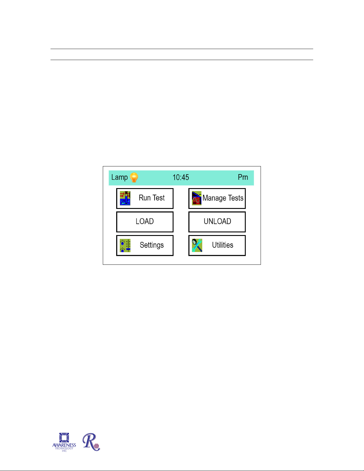
2.3 Main Display Menu Options
Lamp status
Time
Reprint button
The Main display menu options are:
• Run Test explained in Section 2.3.1
• Settings explained in Section 2.3.2
• Manage Tests explained in Section 2.3.3
• Utilities explained in Section 2.3.4
• Load - the reader positions the carrier in the Home position.
• Unload - the reader positions the carrier for ease of removal.
indicator
Figure 2.3-1 Representation of the Main Screen
The status line displays the Lamp status (OFF or ON) and the time. The printer button (Prn) has
two options: 1. to advance the paper, 2. to reprint the last 64 lines of data. NOTE: Prn does not
print graphs, only data.
Stat Fax® 4700 Operator’s Manual Doc. 4700 Rev. G 19
Page 24
2.3.1 Run Test
1 – T3
2 – T4
3 - TSH
4 – TFSH/FSH
5 – T3-Uptake
6 – LH/LH
7 - PRL
8 - hCG
9 - Digoxin
By #
Allows the user to enter a specific test number to recall.
Cancel
Returns to the main power on display screen
By #
Cancel
<<
>>
^
V
Select
SAMPLE
Select Test to RUN
The Run Test feature allows the operator to recall user tests that have been stored in the
instrument’s memory. The instrument stores up to 120 complete test setups in nonvolatile
memory, making it easy for the user to recall complete test configurations.
Select Run Test from the Main display. If no assays have been programmed yet, the
instrument will open to the Create Test screen automatically (see Section 2.3.3 Manage
Tests). Otherwise, tests programmed and saved on the instrument will display sorted by their
test number. When the test is recalled, the user has the option of using the previous saved
curve or reading a new one.
Figure 2.3.1-1 Sample - User Stored Tests
Feature Function
Arrows Use the ^ UP and V DOWN arrow keys to highlight selection; use the
>> side arrows to advance to the next screen; use << arrows for
previous screen
Select The highlighted test is executed once the Select key is pressed
20 Stat Fax® 4700 Operator’s Manual Doc. 4700 Rev. G
Page 25

2.3.2 Settings
Printer Setup
Enables/disables the internal printer. Allows the contrast to be adjusted
Adjust Date
Provides access to the Set Time option Hours, Minutes, Seconds as well
Lamp
Lamp idle feature will automatically turn off the lamp; the default setting is
seconds (45 seconds is the default setting).
Laboratory
Allows a laboratory named to be entered; laboratory name will print out
Strip Format
Allows the user to select 8 Well (A-H) or 12 Well (1-12) format. Note: Test
Strip Carrier Loading and Positioning).
Sound
Provides access to and status of touch screen sound settings (ON or
External
Allows external output to be turned ON or OFF. (Reference the External
Arrow Keys: Utilize the arrow
^
v
Select
Done
Select the Settings option on the main display screen and the Unit Settings will display:
Printer Setup
Adjust Date and Time
Lamp Control
Laboratory Name
keys to scroll up and down
the list of options or press the
option directly from the list;
the option will highlight
Strip Format
Select: The high-lighted
Sound Settings
option is executed once the
Select key is pressed
External Output
Figure 2.3.2-1 Unit Settings
The functions of the Unit Settings features are:
Feature Function
light to dark. Text height options are small, medium and large.
Note Graphs can be printed when the internal printer is set to OFF.
and Time
Control
Name
Settings
Output
Note: It is advisable to print at contrast level set at 3. Higher contrast levels
may degrade after several lengthy printouts.
as Month, Day, Year (MM/DD/YY) or Day, Month, Year (DD/MM/YY)
format.
600 seconds (10 minutes). Lamp Warm up range is between 45 to 120
(reference Checkout Procedure in Section 1.7).
programs may be stored in either format but the strip format setting must
be selected before programming a new assay. (Reference Section 1.6.1
OFF), and sound volume (1=low to 8=high). Sound options are: start up
sound, key press & release and other sounds (i.e. sound when the Quit
button is selected).
Output Section 2.3.2.1 for setup instructions).
Stat Fax® 4700 Operator’s Manual Doc. 4700 Rev. G 21
Page 26

2.3.2.1 External Output
To enable output to be sent to a personal computer, a user must have a USB cable
with Type A and Type B end connections, and use a software application such as
SF_Capture to transmit and store data from the instrument. (Refer to Section 8,
Appendix B for SF_Capture software setup
.)
• Power on the instrument and set the External Output to “ON” by: (a) selecting Settings
from the main display, (b) highlight External Output on the Unit Settings display, (c)
press the Select button, (d) on the External Output Setup display select the ON button
and ensure that the Status field displays ON, (e) select the Save button, and then, (f)
select the Done button.
• Connect the type B end of the USB cable to the type B port of the instrument.
• With the personal computer (PC) powered on, connect the type A end of the USB
cable to a USB port on the PC. (Cable is not supplied with instrument.)
Type A
Figure 1 USB Type A port and connector
Type B
Figure 2 USB Type B port and connector
2.3.2.2 Mouse Connection
®
To use a USB mouse with the Stat Fax 4700
, be sure that the mouse is connected to the
USB port A on the instrument before the instrument is powered on. If the mouse is
plugged in after the instrument is on, it will not be operational.
22 Stat Fax® 4700 Operator’s Manual Doc. 4700 Rev. G
Page 27

2.3.3 Manage Tests
Create Tes t
Edit Test Clone Test
Delete Test
Print Tes t List Exit
Create Test
Depending upon the mode, Create Test allows user to:
Edit Test
Used to change test programming. Editing a test will erase any
stored blank or standard values for that test.
Clone Test
Delete Test
Provides option to delete a test from the user’s stored menu.”
Detailed descriptions of the Modes of Operation may be found in Section 2.5. Select
Manage Tests on the Main display screen and the following options will display
:
Figure 2.3.3-1 Manage Tests options
Feature Function
CAUTION! To
avoid confusion
due to carry over of
test settings, it is
recommended that
users save tests
once they are
created, or exit the
Create Test option
properly before
accessing another
mode. This
ensures that the
instrument’s
memory has been
cleared of all
settings before
creating the next
test or performing
the next operation.
• Name the test
• Select the Mode (Absorbance, Factor, Single Standard, Point-
to-Point, Regression, Cubic Spline, Cutoff)
• Select the Primary Filter
• Select the Differential Filter
• Enable/Disable Blank (Yes or No) Note: Default is ‘yes’ for
Single Standard Mode.
• Set number of blank replicates
• Interpretation Criteria (Positive and Negative interpretation, or
Normal and Valid Ranges)
• Select Units
• Input Decimals
• Enable % Absorbance (Yes or No)
• Input number of Standards, number of replicates
• Input number of Sample Replicates
• Select Axes
• Controls management (Enable; name; number of replicates;
input low/high ranges; input action to take (i.e. warn, continue
or end test); record Lot Number; input expiration date).
Allows user to duplicate an existing test; assigns the next available
test slot number allowing for the test to be stored. The cloned test
can then be edited. This feature provides a programming short cut
when assays with similar programming are needed.
Stat Fax® 4700 Operator’s Manual Doc. 4700 Rev. G 23
Page 28

Manage Tests (Continued)
Change Access Level
Show Version Details
Erase All Tests
Recall Calibration
Print Unit Settings
Filter Voltages
Arrow Keys: Utilize the
^
v
Select
Done
Feature Function
Restore Tests (OEM
models only)
User can choose to restore just one of the pre-programmed
tests, or to restore all of the pre-programmed tests.
Print Test List Prints out the list of stored tests (maximum 120 tests)
Exit Returns to the Main display screen
2.3.4 Utilities
Select Utilities from the Main display screen and Utility Menu options used for diagnostic
troubleshooting purposes will display. The arrow keys control movement up and down the
list of options as well as using the edge of the list to scroll up and down. To select an option
from the list, press the Select button. Press the Done button when finished.
Utility Menu
arrow keys to scroll up and
down the list of options or
press the option directly
from the list; the option will
highlight..
Select: The high-lighted
option is executed once
the Select key is pressed.
Done: Returns to the Main
display screen.
Figure 2.3.4-1 Utility Menu options
Feature Function
Change Access Level Display prompts to ‘Enter Pass Code’. Contact Technical
Support for pass code.
Show Version Details Displays current firmware version, model, serial number, build
date, current time.
Erase All Tests “Please Confirm: Erase All Tests?”
CAUTION: Selecting ‘OK’ will delete ALL stored tests.
Recall Calibration Allows user to restore the original factory settings, including
calibration.
Print Unit Settings Prints all information about an individual instrument’s
calibration settings and other information.
Filter Voltages Displays real time filter wheel voltages; provides option to print
them out
24 Stat Fax® 4700 Operator’s Manual Doc. 4700 Rev. G
Page 29

2.4 General Operation
2.4.1 Bichromatic Differential Operation
The option to operate this instrument using differential absorbance readings is available for
every mode. The absorbance readings at the differential wavelength are subtracted from the
absorbance readings at the operating (primary) wavelength. Use of the bichromatic
differential absorbance values corrects for optical imperfections in the plastic wells and
removes the effects of meniscus and turbidity.
Whenever possible, differential reading is recommended because precision is significantly
improved.
In order to preserve sensitivity, it is important not to choose a differential wavelength where
the chromophore being assayed exhibits substantial absorbance. To test your chromophore,
read a darkly colored solution in the Absorbance Mode at the operating wavelength with no
differential filter, and again at the operating wavelength with the differential filter selection. If
the two absorbance readings are within 10% of each other, then bichromatic differential
reading is beneficial. If the difference between the absorbance readings with and without a
differential wavelength is greater than 25%, then the chromophore is absorbing at or near
the differential wavelength and bichromatic reading at this wavelength is probably not
desirable.
If no bichromatic wavelength is selected, exercise every measure to enhance repeatability
such as checking that well bottoms are not wet, dirty or scratched. Use a blank in the assay
to remove meniscus effect, and cover wells during incubation to prevent dust.
Stat Fax® 4700 Operator’s Manual Doc. 4700 Rev. G 25
Page 30

2.4.2 Unit of Measurement Codes (Unit Code)
Exit
Pos/Neg
Conc ^
1 v
1
Edit
<<
Save Run
Print
Decimals
# Sample Replicates
TEST DEFINITION Final page
Interpretation Mode
Units
SELECT UNITS
To access the list of Unit Codes, select Manage Tests, select Create Test select any mode
except Absorbance, and advance to the Test Definition Final Page. Check the container for
the calibrator(s) to determine the units for results. Select the Units field and the list will
display. Seven units of measurement designations are stored for labeling the concentration
column heading on the printed results plus a blank customizable selection
.
Figure 2.4.2-1 Example – Interpretation Mode
Test Definition - Final page
Conc
IU/mL
g/dL
mmol/L
umol/L
ppm
ppb
Customize
Figure 2.4.2-2 Example –
Option to add a unit of
measure
Create a customized label for the concentration column by selecting the option ‘customize’
from the list of units available. A keyboard will display, enter the desired label name and
press Enter. The custom Unit label will display in the Unit field.
CAUTION: Be sure to use the same units for the calibrators, control criteria and
interpretation criteria within a test.
26 Stat Fax® 4700 Operator’s Manual Doc. 4700 Rev. G
Page 31

lowest absorbance values.
2.5 Modes of Operation
Mode Function
Absorbance Section 2.5.1 - Absorbance mode reads and prints the monochromatic or
bichromatic differential absorbance at the user-selected wavelengths.
Blanking is optional. Most Assays require a mode other than Absorbance
Mode. In this mode, no calculations are made - only absorbance values are
reported.
Factor Section 2.5.2 – In Factor Mode, the endpoint absorbance readings will be
multiplied by a user-entered factor to calculate a result.
Single
Standard
Point-toPoint
Section 2.5.3 – Single Standard mode reads a calibrator, and then
calculates concentrations based on a single-point standard curve passing
through the point (0,0). A blank is required to determine the (0,0) point. A
factor (equal to the concentration of calibrator ÷ the absorbance of
calibrator) is generated in this mode, and then multiplied by subsequent
absorbance readings to determine concentrations.
Section 2.5.4 – The microstrip reader accepts a number of calibrators and
calculates concentrations based on the point-to-point calibration curve. The
resulting calibrator curve is a series of line segments connecting the
calibrator points, which may be entered in ascending or descending order of
absorbance. The direction of slope between the first and second calibrators
determines the direction of the curve. If the direction of the curve changes,
the curve will be flagged as being “invalid” and no interpretations will be
printed.
Unknown samples are calculated as follows:
The unknown sample’s absorbance is read and then compared to the
absorbance of the calibrators. Its concentration is calculated on the segment
connecting the closest points above and below it.
An unknown Sample, with absorbance higher than the calibrator with the
highest absorbance value, is calculated using a line that passes through the
two Calibrator points with the highest absorbance value. An unknown
Sample with absorbance lower than the lowest Calibrator absorbance is
calculated from the line that passes through the two Calibrators with the
Stat Fax® 4700 Operator’s Manual Doc. 4700 Rev. G 27
Page 32

overshoot.
SELECT MODE
Absorbance
Cancel
Factor
Single Standard
^
Point to Point
Regression
v
Cubic Spline
Cut Off
Select
Regression Section 2.5.4 Regression mode accepts a number of calibrators and
calculates concentration values based on a best-fit curve (linear regression).
Cubic Spline Section 2.5.4 – Cubic Spline Mode accepts a minimum of 3 to a maximum of
8 calibrators and calculates concentrations based on the Cubic Spline
(constrained) calibration curve.
Calibrator materials of known concentrations are used to calibrate the
analyzer so that concentrations of unknown Samples are calculated from the
generated curve. The resulting calibrator curve is a smooth curve connecting
the Calibrator points, which may be entered in ascending or descending
order of absorbance. A constraining algorithm is applied to prevent curve
Mode options are located under Manage Tests on the Main display screen. Select Create Test and
the Test Definition screen will display; select the Mode field and the list of Mode options will
display.
Each of the seven (7) modes follow the
same basic pattern of options, with other
variables available for selection dependent
upon the mode being used.
Figure 2.5-1Available Modes
28 Stat Fax® 4700 Operator’s Manual Doc. 4700 Rev. G
Page 33
2.5.1 Absorbance Mode
1st page
Name Exit
Mode
^
Primary Filter 405 v
Differential Filter 630
Blank YES Edit
Print Save >>
TEST DEFINITION
Absorbance
NOTE: Every user should begin by learning to use the Absorbance Mode.
Absorbance mode will read and print sample absorbance values at user selected
wavelengths. Press Manage Tests, press Create Test, and the Test Definition window will
display.
Figure 2.5.1-1 Initial Test Definition display
Note: All of the other modes function the same way but use the measured absorbance to
calculate final results.
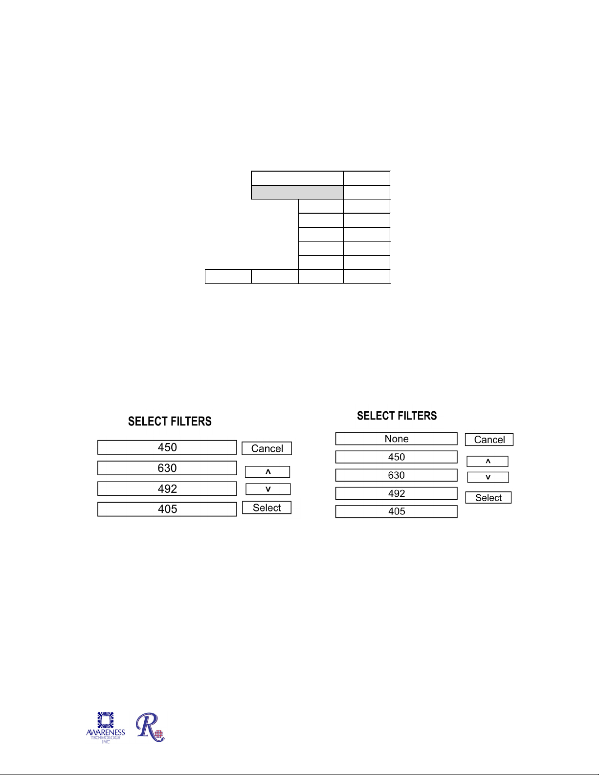
2.5.1.1 Filter Selection
To edit the Primary or Differential Filter wavelength fields, use the arrow keys to advance
to the desired field, and then press the Edit key. The Select Filters screen will display the
available filter options; make a selection and press the Select button.
Primary Filter display Differential Filter display
Stat Fax® 4700 Operator’s Manual Doc. 4700 Rev. G 29
Page 34

2.5.1.2 Offset Absorbance
Name Exit
Mode
^
Primary Filter 405 v
Differential Filter None
Blank NO Edit
Offset Absorbance 0.000
Print Save Run
TEST DEFINITION
Absorbance
^
Enabled YES v
# Replicates 1.0
Range Low Edit
Range High Done
TEST DEFINITION Blank
If Differential Filter is set to "None", then the Offset Absorbance field is displayed.
Figure 2.5.1.2-1Test Definition – Offset Absorbance field displayed
The user should determine the value of the Offset Absorbance. This value will be
subtracted from the absorbance readings to correct for the meniscus effect for the test that
is being run. Select the Offset Absorbance field and enter the user-determined offset
absorbance value. Press the Save button to save the settings.
Offset Absorbance feature is only needed when both of these conditions occur:
• Monochromatic reading
• No blank well
It is a mathematical blank to correct for the differential between air and liquid with a
meniscus.
To determine the user-entered value, pipette a volume of wash buffer into a well that is
equal to the total volume in test wells at the read time.
For example, if the well has 100µl of Substrate Part A per 100 µl of Substrate Part B, plus
50µl of stop solution, the total volume in the test wells at the read time is 250µl. Therefore
read the absorbance of 250µl of colorless wash buffer to determine the correct value for
the Offset Absorbance. Typical values are from .250 to .400A.
2.5.1.3 Blank
The Test Definition Blank screen will display when the Blank field is selected. This screen
allows for the Blank setting to be enabled (Yes or No); and for inputting the number of
Replicates. Press the Done button when editing is completed.
30 Stat Fax® 4700 Operator’s Manual Doc. 4700 Rev. G
Figure 2.5.1.3-1 Test Definition Blank display
Page 35

2.5.1.4 Lamp Saver
Exit
Factor
^
Control 1
v
Control 3 Edit
<< Save Run >>
10
Disabled
TEST DEFINITION 2nd page
Disabled
Disabled
Ten minutes after reading the last sample, the Lamp Idle Timeout feature will
automatically turn off the lamp. 600 seconds (ten minutes) is the default setting. The
Minimum Lamp Warmup will occur (45 seconds is the default setting), and then operation
will resume where it left off. Refer to Settings to access the Lamp Control feature.
2.5.2 Factor Mode
The Factor Mode Test Definition first page will display the available options: Name, Mode
(Factor), Primary Filter, Differential Filter, and Blank. Enter each as done in Absorbance
Mode Section 2.5.1.
After pressing the advance arrows ‘>>’ in the first screen, the Test Definition second page
will display and allow editing of Factor and Controls. Use the arrow keys to advance through
the options; press the Edit key to change the values displayed on the screen.
NOTE: The Factor comes from the assay package insert or from a previous assay in the
Single Standard Mode.
Selecting any of the Control fields will open a Test Definition Control screen with options to
enable the Control (Yes or No), input the number of Replicates, Name the Control, input a
Low and a High Range, set the Action to Take (Warn, Continue or End Test), input a Lot
Number, and input an Expiration Date. Press the Done button when finished with editing
fields.
Stat Fax® 4700 Operator’s Manual Doc. 4700 Rev. G 31
Figure 2.5.2-1 Factor Mode Test Definition – 2
nd
Page
Page 36

Factor Mode (continued)
TEST DEFINITION Control 1
Enabled
YES
# Replicates 1
Name ^
Range Low v
Range High
Action Edit
Lot Number Done
Expiration [mm.yyyy]
Location
Control 1
Warn, Co ntinue
Exit
Pos/Neg
Conc ^
1 v
1
Edit
<< Save Run Print
Units
Decimals
# Sample Replicates
TEST DEFINITION Final page
Interpretation Mo de
When Controls are read in duplicate, the mean of the duplicates can be calculated and that
one value used, or, each Control can be required to fall within the ranges individually. The
instrument will prompt ‘Check Mean?’ once duplicate Controls are selected.
Figure 2.5.2-2 Test Definition Control screen
The Factor Mode Test Definition Final Page will display and allow editing of Interpretation
Mode, Units, Decimals, and number of Sample Replicates. Selecting the Units field on the
Factor Mode Test Definition – Final Page will display a list of seven measurement
designations including a customizable selection, which are stored for labeling the
concentration column (see Section 2.4.2 Unit of Measurement Codes). Use the arrow keys
to advance through the options and press the Edit key to change the values of the selections
on the screen. Press Save to save the selections.
Figure 2.5.2-3 Factor Mode Test Definition - Final Page
“Decimals” refers to the number of places after the decimal point that will be displayed in a
result. For example, a user has select that results should report out to 2 decimal places. The
calculated result is 0.235. Rounding will result in this being reported as 0.24. If the calculated
result is 0.234, the result will be reported as 0.23.
32 Stat Fax® 4700 Operator’s Manual Doc. 4700 Rev. G
Page 37

Factor Mode (Continued)
TEST DEFINITION Interpretation
Interpretation Pos/Neg ^
v
NO Edit
Done
Pos >=
Neg <
Reversed
Interpretation ^
Normal Range Low v
Normal Range High
Valid Range Low Edit
Valid Range High Done
TEST DEFINITION Interpretation
Normal
NOTE: Double check
Selecting the Interpretation Mode field will open the Test Definition Interpretation screen for
editing the Interpretation controls. Use the arrow keys to advance through the options, press
the Edit key to change the value of the selection.
Editing the Interpretation Pos/Neg field will display the Interpretation Normal option for
inputting Normal Range Low, Normal Range High, Valid Range Low, or Valid Range High.
Press the Done button when editing is completed.
that the interpretation
information you entered
is correct.
Figure 2.5.2-4 Factor Mode Test Definition –Pos/Neg Interpretation
Figure 2.5.2-5 Factor Mode Test Definition –Normal Interpretation
Press the Done button when editing is completed.
Stat Fax® 4700 Operator’s Manual Doc. 4700 Rev. G 33
Page 38

2.5.3 Single Standard Mode
1st page
Name Exit
Mode
^
Primary Filter 405 v
Differential Filter 630
Blank YES Edit
Print Save >>
TEST DEFINITION
Single Standard
^
Enabled
1.0 v
# Replicates
Range Low Edit
Range High Done
TEST DEFINITION Blank
Figure 2.5.3-1 Single Standard Mode Test
Figure 2.5.3-2 Blank options
Exit
Standard Conc
# Std Replicates ^
Control 1
Control 2 v
Control 3 Edit
<< Save Run >>
Disabled
Disabled
TEST DEFINITION 2nd page
10
Disabled
To operate in Single Standard Mode, select Manage Tests and then select Create Test. The
Test Definition screen will display. Select the mode field and the Select Mode screen will
display the list of modes. Use the arrow keys to scroll through the mode selections to the
desired selection and press Select, or use the stylus to highlight Single Standard.
The Single Standard Mode Test Definition first page will display the available options: Name,
Mode (Single Standard), Primary Filter, Differential Filter, and Blank. These operate the
same as in the Absorbance Mode except that the Blank is required, therefore ‘YES’ will
automatically appear in the Blank enabled field.
Definition – 1st Page
The Single Standard Mode Test Definition second page will display and allow editing of
Standard Concentration, Controls, and number of Standard Replicates. Use the arrow keys
to advance through the options and press the Edit key to change the values of the selections
on the screen.
Figure 2.5.3-3 Single Standard Mode Test Definition –2
Selecting any of the Control fields will open a Test Definition Control screen with options to
enable the Control (Yes or No), input the number of Replicates, Name the Control, input a
Low and a High Range, set the Action to Take (Warn, Continue or End Test), input a Lot
Number, and input an Expiration Date. Press the Done button when finished with editing
fields.
34 Stat Fax® 4700 Operator’s Manual Doc. 4700 Rev. G
nd
Page
Page 39

Single Standard Mode (Continued)
Enabled NO
# Replicates 1
Name ^
Range Low v
Range High
Action Edit
Lot Number Done
Expiration [mm.yyyy]
Location
Control 1
Warn, Co ntinue
TEST DEFINITION Control 1
Exit
Pos/Neg
Conc ^
1 v
1
Edit
<<
Save Run Print
Decimals
# Sample Replicates
TEST DEFINITION Final page
Interpretation Mo de
Units
TEST DEFINITION Interpretation
Interpretation Pos/Neg ^
v
NO Edit
Done
Pos >=
Neg <
Reversed
NOTE: Double check
is correct.
When Controls are read in duplicate, the mean of the duplicates can be calculated and that
one value used, or, each Control can be required to fall within the ranges individually. The
instrument will prompt ‘Check Mean?’ once duplicate Controls are selected
Figure 2.5.3-4 Test Definition Control screen
The Single Standard Mode Test Definition Final page will display and allow editing of
Interpretation Mode, Units, Decimals, and number of Sample Replicates. Use the arrow keys
to advance through the options; press the Edit button to change the values of the selections
on the screen. Press Save to save the selections.
Figure 2.5.3-5 Single Standard Mode Test Definition - Final Page
Selecting the Interpretation Mode field will open the Test Definition Interpretation screen for
editing Interpretation controls. Use the arrow keys to advance through the options, press the
Edit key to change the value of the selection. Press the Done button when editing is
complete.
Figure 2.5.3-6 Single Standard Mode Test Definition - Interpretation
Stat Fax® 4700 Operator’s Manual Doc. 4700 Rev. G 35
that the interpretation
information you entered
Page 40
2.5.4 Multi-Point Modes (Point-to-Point, Regression and Cubic Spline)
Absorbance
Cancel
Factor
Single Standard ^
Point to Point
Regression v
Cubic Spline
Cut Off Select
SELECT MODE
1st page
Name Exit
Mode
^
Primary Filter 405 v
Differential Filter 630
Blank NO Edit
Print Save >>
Point to Point
TEST DEFINITION
MULTI-POINT
®
The Stat Fax
Cubic Spline.
In Point-to-Point and Cubic Spline modes, the standard concentrations must be read in
either increasing or decreasing order.
All of the Test Definition screens, use of Controls, and items related to Interpretations work
the same for each type of multi-point. Use the arrow keys to scroll through the mode
selections to the desired selection and press Select or use the stylus to highlight selections.
The Test Definition first page displays the available options.
4700 offers three varieties of multi-point modes: Point-to-Point, Regression and
Figure 2.5.4-1 Select Mode
36 Stat Fax® 4700 Operator’s Manual Doc. 4700 Rev. G
Figure 2.5.4-2 Point to Point Mode – 1
st
page
Page 41

Multi-Point Modes (Continued)
% Absorbance
NO Exit
Standards 5
# Std Replicates 1 ^
Axes
Control 1 Disabled v
Control 2 Disabled
Control 3 Disabled Edit
<< Save Run >>
Y=Abs X=Conc
TEST DEFINITION 2nd page
Standards
Exit
Number of Standards 3 ^
Std1 Concentration 10.0 v
Std2 Concentration 20.0
Std3 Concentration 30.0 Edit
Done
The Test Definition second page will display and allow use of % Absorbance, editing of the
number of Standards and to enable the use of Controls. Note: The number of Standards
must be at least two for Point-to-Point and Regression. Cubic Spline mode requires at least
three Standards.
The Test Definition second page options include use of % Absorbance, Standards, number
of Standard Replicates, selection of Axes, and Controls.
Note: Point-to-Point and Regression require at least two Standards. Cubic Spline mode
requires at least three.
Figure 2.5.4-3 Test Definition – 2
nd
Page
% Absorbance assigns a value of 100% to the first Standard, which must be the Standard
with the greatest absorbance. Then the % absorbance relative to the first Standard is
calculated for each Standard and Sample, in addition to a concentration value. The %Abs
value is displayed in the Interpretation field of the report. This mode does not support ln, logit
or log scales for the absorbance axis. Upon recall of a % Absorbance mode test, the user
will be asked whether to reread the highest value Standard.
Select the Standards field and the Standards Test Definition screen will open.
After entering or editing the number of standards, a dialog box will open prompting the user
for a Yes or No response to ‘Off Curve OK?’ “Off Curve” allows the user to determine
whether concentration results are reported when an absorbance is greater than or less than
the Standards that make up the curve. Select ‘Yes’ to report the results that are ‘off curve’
otherwise select ‘No’.
Stat Fax® 4700 Operator’s Manual Doc. 4700 Rev. G 37
Figure 2.5.4-4 Standards Test Definition Screen
Page 42

Multi-Point Modes (Continued)
Dup#
Dupl 1
Dupl 2 1 X
2
3
Using Edited Curve
S1 = .789 Deleted
r=0.999
v=1.2077
Re-calculating……
Y = Logit(Abs) X = Log(Conc)
Y = Ln(1000*Abs) X = Ln(Conc)
When Duplicate Standards are used, the curve may be edited by deleting one of a pair of
standards. Once the curve has been read, before the ‘Accept’ or ‘Print’, select ‘Edit’. Using
the stylus, select the duplicate standard to be deleted. As shown below, they are labeled as
‘Dupl I’ and ‘Dupl II’.
X
m=0.738
Figure 2.5.4-5 Duplicate Standards Screen
An “X” will appear in the location on the display that is to be deleted. The curve will be
recalculated and the options to Accept, Edit, Print or Quit will be available.
Axes selections include linear-linear, ln (= natural log)-linear, linear-ln, or ln-ln calculations. A
logit-log calculation is also available. Absorbance, or ln of (1000 * absorbance), is always on
the “Y” axis. Concentration, or ln of concentration, is always on the “X” axis.
When using Regression mode, the standard curve, y-intercept (y), slope (m) and Correlation
coefficient ® will be printed. Printing the graph is also optional.
SELECT AXES
Figure 2.5.4-6 Axis Selection Screen
38 Stat Fax® 4700 Operator’s Manual Doc. 4700 Rev. G
Page 43

Multi-Point Modes (Continued)
SELECT AXES
Cancel
Y=Ln(1000*Abs) X=Conc ^
v
Y=Ln(1000*Abs) X=Ln(Conc) Select
Y=Logit(Abs) X=Lo g(Conc)
Y=Abs X=Ln(Conc)
Y=Abs X=Conc
The program
Calculation Explanation
“Y= ABS, X=CONC” Both the absorbance data (y) and the concentration
data (x) are linear.
“Y=Ln (1000*ABS), X=Conc” The natural log of the absorbance is plotted against
the concentration. The absorbance values are
multiplied by 1000 before taking the logs.
“Y=ABS, X=Ln(Conc)” Absorbance is plotted against the natural log of the
concentration.
“Y= Ln (1000*ABS), X=Ln(Conc)” The natural log of the absorbance is plotted against
the natural log of the concentration.
“Y= Logit(Abs), X= Log(Conc)” Select to calculate unknowns using the equation:
Abs Logit = Ln [(sample/0 cal) / 1-(sample/0 cal)]
Refer carefully to the Reagent Kit product insert for correct selection.
NOTE: Remember log of 0 is undefined so do not set concentration to 0 (zero) on a
logarithmic scale.
For Point-to-Point and Regression modes, number of standards can be between two and
eight. Cubic Spline mode requires at least three standards.
The Log / Logit option is available under the Point to Point Mode, Regression Mode, and the
Cubic Spline Mode. Concentrations must be greater than zero in this axes mode..
automatically
increases the
number of
Standards by
one
When using a non-linear axis:
• If absorbance of a Sample is > than the highest calibrator's absorbance, “ ****** “ is
reported for the Concentration
• Standards must be read in descending absorbance order
• If no Standard programmed has a 0.0 concentration assigned to it, an additional Standard
is forced, and the concentration for that Standard is replaced with a series of stars [ **** ]
Stat Fax® 4700 Operator’s Manual Doc. 4700 Rev. G 39
Figure 2.5.4-7 Log/Logit Options
Page 44

Multi-Point Modes (Continued)
TEST DEFINITION Control 1
Enabled YES
# Replicates 1
Name ^
Range Low v
Range High
Action Edit
Lot Number Done
Expiration [mm.yyyy]
Location
Control 1
Warn, Co ntinue
Exit
Pos/Neg
Conc ^
1
v
1
Edit
<< Save Run Print
Units
Decimals
# Sample Replicates
TEST DEFINITION Final page
Interpretation Mo de
Selecting any of the Control fields will open a Test Definition Control screen with options to
enable the Control (Yes or No), input the number of Replicates, Name the Control, input a
Low and a High Range, set the Action to Take (Warn, Continue or End Test), input a Lot
Number, and input an Expiration Date. Press the Done button when finished with editing
fields.
When Controls are read in duplicate, the mean of the duplicates can be calculated and that
one value used, or, each Control can be required to fall within the ranges individually. The
instrument will prompt ‘Check Mean?’ once duplicate Controls are selected.
The Test Definition Final page will display Interpretation Mode, Units, Decimals, and number
of Sample Replicates.
40 Stat Fax® 4700 Operator’s Manual Doc. 4700 Rev. G
Figure 2.5.4-8 Test Definition Control screen
Figure 2.5.4-9 Test Definition – Final Page
Page 45

Multi-Point Modes (Continued)
Interpretation ^
Normal Range Low v
Normal Range High
Valid Range Low Edit
Valid Range High
Done
TEST DEFINITION Interpretation
Normal
Interpretation ^
v
NO Edit
Done
Neg <
Reversed
TEST DEFINITION Interpretation
Pos/Neg
Pos >=
NOTE: Double check
is correct.
Selecting the Interpretation Mode field will open the Test Definition Interpretation screen for
editing the Interpretation controls.
that the interpretation
information you entered
2.5.4-10 Test Definition –Pos/Neg Interpretation
Editing the Interpretation Pos/Neg field will display the Interpretation Normal option for
inputting Normal Range Low, Normal Range High, Valid Range Low, or Valid Range High.
Press the Done button when editing is completed.
Figure 2.5.4-11 Test Definition – Normal Interpretation
Stat Fax® 4700 Operator’s Manual Doc. 4700 Rev. G 41
Page 46

2.5.5 Cut Off Mode
Absorbance Cancel
Factor
Single Standard ^
Point to Point
Regression v
Cubic Spline
Cut Off Select
SELECT MODE
1st
Primary Filter
405
v
Differential
Blank
NO
Print
Save
>>
Figure 2.5.5-2 Sample of Cut Off Mode Test
Many qualitative assays interpret results based on a pre-determined, or cut off, absorbance
such that a sample absorbance greater than the cut off absorbance is interpreted as positive
(or negative) and samples with absorbance less than the cutoff be interpreted as negative
(or positive). Companies that manufacture these assays use a variety of means of obtaining
(reading or calculating) the essential cut off point. Stat Fax
®
4700 employs a universal
equation that can be adapted to fit most commercially available kits by inserting user-entered
factors ‘X’ and/or ‘Y’ as well as a coefficient ‘F’. The equation is (X)(mNC) + (Y)(mPC)+F =
COV (Cut Off Value).
In the Cut Off Mode, ‘X ‘is multiplied by the mean of the negative controls. ‘Y’ is multiplied by
the mean of the positive controls, and each of these two numbers is added to ‘F’ to arrive at
the Cut Off Value (COV). The ‘X’, ‘Y’ and ‘F’ factors can be positive or negative numbers,
one or zero, or decimals such as 0.5 to fit the test requirements provided in the Kit package
insert or as instructed by the Kit manufacturer. In this mode be careful to enter all QC
parameters completely and correctly. They are usually provided as Absorbance limits.
To operate in Cut Off Mode, select Manage Tests and then select Create Test. The Test
Definition screen will display. Select the Mode field and the Select Mode screen will display
the list of modes. Use the arrow keys to scroll through the mode selections to the desired
selection and press Select or use the stylus to highlight Cut Off.
Figure 2.5.5-1 Initial Test Definition
display
TEST DEFINITION
Name
page
Exit
Mode Cut Off ^
Filter
630
Definition 1st page
42 Stat Fax® 4700 Operator’s Manual Doc. 4700 Rev. G
Page 47

Cut Off Mode (Continued)
COV= Exit
X=
1
Y= 1 ^
F= 0 v
Neg Ctrl Enabled
Pos Ctrl Enabled Edit
QC Criteria
<< Save
Run >>
TEST DEFINITION Cutoff
X*mNC+Y*mPC+F
COV, mNC, mPC
TEST DEFINITION Control 1
Enabled YES
# Replicates 1
Name ^
Range Low 0.2 v
Range High 0.4
Action Edit
Lot Number Done
Expiration [mm.yyyy] 03.2016
Neg Ctrl
Warn, Co ntinue
122
The Cut Off Mode Test Definition first page displays the available options: Name, Mode (Cut
Off), Primary Filter, Differential Filter, and Blank.
The Test Definition Cut Off second page allows editing of Cut Off Value (COV), values of X,
Y, and F; Negative Control; Positive Control; and QC Criteria.
Figure 2.5.5-3 Sample of Cutoff Mode Test Definition 2nd page
Selecting any of the Control fields will open a Test Definition Control screen with options to
enable the Control (Yes or No), input the number of Replicates, input a Low and a High
Range, set the Action to Take (Warn, Continue or End Test), input a Lot Number, and input
an Expiration Date. Press the Done button when finished editing fields.
Stat Fax® 4700 Operator’s Manual Doc. 4700 Rev. G 43
Figure 2.5.5-4 Test Definition Control screen
Page 48

Cut Off Mode (Continued)
X*mNC+Y*mPC+F
X*mNC+F
^
Y*mPC+F
v
X*mCC+F
Cancel
Select
See explanation
Note: When Cut Off Controls are read in multiples (replicates), the mean of the replicates can
be calculated and that value used, or each Control can be required to fall within the ranges
set. “Check Mean?” will display if replicate Controls are selected.
Selecting the ‘COV =’ field will open the Select COV Formula screen. In addition to the
universal equation, Stat Fax
When COV is the Cut Off Absorbance Value, mNC is the mean of the Negative Controls;
mPC is the mean of the Positive Controls. X, Y, and F are user-entered coefficients that can
have any positive or negative numerical value including zero and 1.
Highlight the desired formula from the list and press the Select button.
of choices in the
table on the next
page.
®
4700 offers three optional formulas.
Figure 2.5.5-5 Cut Off Formula Screen
.
44 Stat Fax® 4700 Operator’s Manual Doc. 4700 Rev. G
Page 49
Cut Off Mode (Continued)
X*mean(NC) + Y*mean(PC) + F
Universal equation, used to calculate the cut off value
X* mean(NC) + F
Use this equation if only negative controls are used to
Y * mean(PC) +F
Use this equation if only positive controls are used to
X*mean(CC) + F
COV = cut off value for positive or negative interpretation
COV Formula Explanation
based upon readings of positive and/or negative controls.
In this equation, NC and PC are used to determine the
COV (cut off value).
Enter the variables provided in the package insert.
This will calculate the mean of the positives and the mean
of the negatives.
determine the COV.
determine the COV.
For interpretation, you may choose either the Regular Cut
Off Mode (positive >= cutoff, negative < cutoff), or the
Reverse Cut Off Mode. With the Reverse Cut Off option,
the Samples with values lower than the cut off are labeled
as “positive”. If you choose this option, be careful to follow
the < and > signs in the prompts for entering cut offs and
ranges.
Stat Fax® 4700 Operator’s Manual Doc. 4700 Rev. G 45
X = a variable provided in the Assay Kit package insert.
NOTE: X will equal 1 if no value of variable provided.
mCC = the calculated mean of the absorbance values of
the cut off controls when test is run
Blanking is optional, dependent upon the Assay Kit
F = factor added to the mCC. If needed, this value is
provided in the Assay Kit package insert. If none provided,
use zero for the value of F.
Positive and/or negative controls may be used for QC
criteria.
Page 50
Cut Off Mode (Continued)
TEST DEFINITION Cutoff Quality
Minimum COV
^
Maximum COV
v
(mPC/mNC).=
(mPC-mNC).= Edit
Reversed
NO Done
Note: ‘Reversed’ field is ‘YES’ when low absorbances are positive and high absorbances are
negative, ‘Blank’ is not subtracted.
Exit
Pos/Neg
Abs/COV ^
3 v
1
Edit
<< Save Run Print
TEST DEFINITION Final page
Interpretation Mo de
Decimals
# Sample Replicates
Units
TEST DEFINITION Interpretation
Interpretation Pos/Neg ^
v
NO
Edit
Done
Pos >=
Neg <
Reversed
Figure 2.5.5-7 Cut Off Mode Test
Figure 2.5.5-8 Cut Off Mode Test
Selecting the QC Criteria field opens the Test Definition Cutoff Quality screen:
(mPC / mNC): Enter the lowest acceptable
ratio for the mean of the positive controls to the
mean of the negative controls
(mPC – mNC): Enter the lowest acceptable
difference for the mean absorbance of the
Figure 2.5.5-6 Cut Off Mode – Quality
Criteria screen
If the Reversed field reads ‘YES’ the samples with values lower than the cutoff are labeled
as positive. In addition, the Blank is not subtracted in the Reverse Cut Off option. Pay close
attention to “<” less than and “>” greater than symbols when entering control limits in this
case.
The Cut Off Mode Test Definition final page displays Interpretation Mode, Units, Decimals,
and number of Sample Replicates.
positive controls minus the mean absorbance
of the negative controls.
Definition - Final page
NOTE: Double check that the COV
calculations and interpretation information
you entered is correct.
Definition – Interpretation
46 Stat Fax® 4700 Operator’s Manual Doc. 4700 Rev. G
Page 51

Cut Off Mode (Continued)
Interpretation
^
Normal Range Low
v
Normal Range High
Valid Range Low
Edit
Valid Range High
Done
TEST DEFINITION Interpretation
Normal
Figure 2.5.5-9
By selecting Pos/Neg, Positive and Negative Interpretations can be entered. It is not
necessary to enter both Positive and Negative. These can also be set to be evaluated in the
reverse, where Positive is LESS than or equal to (<=) the value entered.
From the Interpretation screen for Pos/Neg, selecting the Interpretation Pos/Neg field will
display the Normal option for inputting Normal Range Low, Normal Range High, Valid Range
Low, or Valid Range High.
Press the Done button when finished
editing.
Test Definition - Interpretation
Stat Fax® 4700 Operator’s Manual Doc. 4700 Rev. G 47
Page 52
3. Cleaning and Maintenance
3.1 Cleaning
3.1.1 Exterior
CAUTION: Solvents such as acetone or paint thinner will damage the
instrument! Use only water and recommended cleaners! Avoid abrasive
cleaners. The display area is liquid-resistant, but is easily scratched.
The exterior of the instrument may be cleaned with a soft cloth using plain water. If needed,
a mild all-purpose (nonabrasive) cleaner may be used. A 10% solution of chlorine bleach
(5.25% Sodium Hypochlorite) or 70% isopropyl alcohol may also be used as a disinfectant.
Take special care not to spill any liquid into the read well.
3.2 Maintenance
3.2.1 Calibration and Linearity
Each instrument is calibrated during manufacturing using standards that are traceable to the
National Institute for Standards and Testing (NIST), and is tested to verify its linearity to 3A.
This preset calibration is very stable. Absolute calibration can be verified with the use of
NIST filters, or by periodic comparison to a reference instrument that is known to be
calibrated to NIST filters.
Absolute calibration can be verified using a specifically designed product called DRI-DYE
Check Strips, available from your instrument supplier.
®
The best way to assure quality instrument performance is to include a sufficient number of
controls in each assay to cover the entire operational range.
In vertical photometry, the fill volume and degree of meniscus determine the pathlength; and
absorbance is proportional to pathlength. Since lab test results are typically based upon
standards rather than upon absolute absorbances, the linearity of the instrument is the more
critical indicator of instrument performance.
A reduction in linearity may be indicative of filter deterioration. In this event, filter
replacement is required for continued reliable operation. A monthly verification of instrument
linearity is generally required to comply with regulatory agencies.
DRI-DYE® Check Strips can also be used to verify linearity.
Alternately, the degree of linearity can be checked by reading a 1:2 serial dilution of a
material having a peak absorbance at or near one of the wavelengths, and observing a 1:2
ratio in the absorbance readings.
If you prepare dilutions to verify linearity, uniform pipetting (pathlength) and minimal transfer
error are important, since the tolerance limits which you will establish must take into
consideration the sources of error that are not due to the instrument.
Pipetting errors can be identified by comparing duplicate readings. The instrument should
give the expected value ± (1% of the expected value + .01A).
48 Stat Fax® 4700 Operator’s Manual Doc. 4700 Rev. G
Page 53

Calibration and Linearity (Continued)
For example, if the 1/4 dilution reads .520 A, then you can expect your 1/2 dilution sample to
read twice as much or 1.04 A ± [(1% of 1.04) +0.01 A], which is ± .02.
A good working instrument would then give a result between 1.02 A and 1.06 A. You will
know that your filters are deteriorating when darkly colored solutions consistently read lower
than expected.
Since the procedures for verifying the calibration and linearity of a vertical photometer are
quite cumbersome and not conducive to stringent criteria, the best way to assure quality
instrument performance is with DRI-DYE
3.2.2 Storage
The instrument may be stored under the following recommended environmental conditions:
• Temperature: 10 to 50°C
• Humidity: Less than 80% relative humidity, non-condensing.
Store the instrument using original packaging if possible.
Perform the following steps before storing:
• Place the instrument in the original packaging material.
®
Check Strips.
• When returning the instrument to service from storage, it is recommended that
functional tests be performed as if setting up the instrument for the first time.
Stat Fax® 4700 Operator’s Manual Doc. 4700 Rev. G 49
Page 54

4. Troubleshooting
If the factory default settings, which include stored calibration,
4.1 Messages and Flags
Messages are displayed to alert the operator when certain limits are approached. After displaying
the warning the instrument will continue to function normally.
Flags are displayed, for example, when an invalid range is entered. They are intended to help the
user correct the problem. Some error messages appear as dialog boxes that require action in order
to clear; others appear on the display screen and appear on the printout.
Message/Flag Explanation
“>10**6” Appears in Concentration Column when Concentration is
greater than 10**6 (column only prints six characters
maximum)
“******”
“>3” Prints in ABS column if an absorbance is greater than the
“%Absorbance Mode should
not be used with negative
absorbances!”
“Assay Cannot Be Edited!” User has tried to edit an OEM preprogrammed test that has
“Cannot match test
wavelength with filters
currently installed on device!
• A sample has exceeded the absorbance of the reference
well in a log-logit test. Curve Axes is Y=Logit(Abs),
X=Log(Conc) and Absorbance >reference(zero)
absorbance value.
• Will print if a curve with a log axis tries to log a zero, a
negative number, or an invalid curve has been read.
• Prints in Concentration column whenever an error occurs
while calculating the concentration.
maximum readable absorbance for the device.
This message will display if the user is in %Absorbance Mode
and a standard is read which has a negative absorbance.
flag set to prevent it from being edited.
Indicates that a filter has been changed and a test has been
recalled that was stored before the filter change. Create and
store a new test with the new filter(s).
“Carrier out of position” This message will be posted if the carrier is not loaded in the
correct beginning position, with A1 the first well to be read.
“Default settings loaded.”
do not load, then default parameters are used.
50 Stat Fax® 4700 Operator’s Manual Doc. 4700 Rev. G
Page 55

Differential filters.
Messages and Flags (Continued)
Message/Flag Explanation
“Do not select the same filter
for primary and differential”
Appears on Page 1 of Test Definition when the same
wavelengths are entered for both the Primary and the
“EQ” This is reported when a Sample is less than the POS cutoff
and greater than the NEG cutoff concentration. (If it is
reversed, then the sample is > value POS cutoff and < value
NEG cutoff.)
“Factory Settings Restored””
OR
“User Settings Restored “
One of these messages can be triggered when the operator
chooses to restore parameters or could be seen at startup if
the unit is forced to recover from bad settings.
“Invalid Curve!” This message indicates that readings for standards cannot be
used to obtain a valid curve for the calculation mode being
used. If duplicate standards are used, the user has the option
to edit the curve if there are enough points (minimum 3 for
Point-to-Point and Regression; minimum 4 for Cubic Spline).
“Invalid Curve – Log Error” An error in the creation of a curve or readings of a negative
absorbance will result in this message, followed by Test
Ended.
”log(<=0)” Prints in Interpretation column whenever a curve axis mode
with a log tries to log a zero or negative number.
“LOW”, “HIGH” Prints in Interpretation column whenever a value is lower or
higher than the range of values entered to create the test.
“Mechanism Error”
“Mechanism Jam
Indicates that the mechanism is not receiving any updated
position information from the sensors.
• Be sure you use the correct carrier.
• Check for incorrectly placed carrier and free the jam,
otherwise notify Technical Support
“NEG” Negative – prints if a Sample is <NEG value (or if reversed,
sample is >NEG value).
“Not enough wells selected to
run assay as defined”
This indicates that the “# Wells” selected were too few to run
the Blanks/Standards/Controls as defined in the test.
Stat Fax® 4700 Operator’s Manual Doc. 4700 Rev. G 51
Page 56

Messages and Flags (Continued)
Message/Flag Explanation
“OUT” Blank is outside min/max range or sample is outside low/high
valid range values It also appears in Cubic Spline mode, when
the sample is outside the range of valid standards
“POS” Sample is >= POS value (or if reversed, sample is <=POS
value.
“Pos must be greater than or
equal to Neg!”
“Range Error” This indicates there is a limit to the range of numbers that can
>Ref Prints when a sample exceeds the absorbance of the
Test Data Corrupted!
OR
Test Definition Corrupted!
This message appears during test definition when the user is
defining positive/negative interpretations. A value was entered
for both the positive and negative, but the positive value is less
than the negative value entered.
be entered.
reference well in a log-logit test. This is usually due to the
calibrator concentrations being entered incorrectly or the
calibrators being pipetted into the strip incorrectly. The first, or
"Zero" calibrator must have the highest absorbance (darker)
and the remaining calibrators must be of descending
absorbance and increasing concentration.
Test (assay) Data (including calibration data) does not match
what was stored.
OR
Test Definition does not match the data stored.
Once a test shows that it is corrupted, there is no way to edit
the test. It must be reprogrammed.
“When reversed, pos must be
less than neg!”
“Wrong date format
(mm.yyyy)!”
52 Stat Fax® 4700 Operator’s Manual Doc. 4700 Rev. G
If using both positive and negative interpretations during test
definition, AND if the positive value is greater than the
negative value, AND Reverse has been selected, this
message will be posted.
This message indicates the expiration date for a control is not
entered in the correct format.
Page 57

"i2c Bus error, 0xNN. Unit
If restarting the instrument does not clear this message,
"BAD" next to a filter
This message will be posted if an assay was previously
“Calibration Checksum Faulty”
Contact Technical Support
“Check unit calibration”
In the event calibration has become corrupted. Recall
“Default settings loaded”
Retrieval of unit parameters changed since the instrument was
“Error: Offset value out of
Offset value is not in the range of 20 – 250 – contact technical
Error Saving Assay Data!
This indicates the instrument is not able to store assay
4.2 Error Messages
Error Messages are displayed when the instrument fails to operate. They are intended to help the
user locate the problem. Some error messages require action in order to clear them. Most require
help from technical support.
Error Message Explanation
may need service. Try poweroff, wait, power-on"
Or
“Check Calibration”
range”
“Factory Data Not Saved” Contact Technical Support
contact technical support.
programmed with a filter that is no longer in the instrument.
Delete or Edit the filters. If this is not the problem, contact
technical support.
Calibration from the Utility Menu can be used to restore the
Factory Calibration.
first shipped from the factory could not be completed – the
original factory unit parameters were restored.
support
information into memory. If less than 120 assays have already
been stored, contact technical support.
“Factory Settings Invalid”
or
“User Settings Invalid “
“Home Sensor Malfunction” This occurs when the mechanism travels to the front and then
“Lamp/Filter Volts Low” This can indicate the use of a faulty or wrong type of carrier.
Stat Fax® 4700 Operator’s Manual Doc. 4700 Rev. G 53
Contact Technical Support
travels back, searching for home, and finds that it has gone too
far. Contact technical support.
If the error message appears when the instrument is turned on,
but before attempting to read a strip, be sure that the light is
on. If not, check the voltage to the lamp and replace the lamp if
necessary. If problem continues, contact Technical Support.
Page 58

“Mechanism Error”
"Mechanism Timeout"
Indicates that the motor appears to be turning but no
Contact technical support.
“Updating internal firmware”
If the system finds an old version of FTDI firmware, flag
turn off the unit until the update is complete.
“Abnormal filter index cnt=x”
During startup, if the filter wheel index count does not get
Error Messages (Continued)
Error Message Explanation
“Mechanism Jam”
Indicates that the mechanism is not receiving any updated
position information from the sensors.
Be sure to use the correct carrier.
Check for badly placed carrier and free the jam. 3.
Contact Technical Support.
response is received from the sensors.
message displays and it is updated automatically. Do not
“Please turn instrument off, pause,
then back on. Call service if
problem persists.”
OR
Filter Wheel Error, cnt = “x”
FTDI initialization error
===========================
Hardware Init Error (#10)
“Wheel Speed out of range”
“Wheel not spinning properly” This message will be posted if the ‘Wheel Speed out of
3 consecutive readings that are either 4, 6, or 8, this error
message will show on the display.
When starting an assay, if the filter count does not match
the count determined at startup, this error message will
show on the display. “x” = the last count.
This message will be seen if the FTDI startup initialization
fails, tries again, but then fails a second time.
=======================================
If the FTDI initialization fails again, the user will see this
message. If turning the instrument off and then back on
does not resolve the error, there is a Troubleshooting
button which requires contacting Technical Support for a
passcode.
This message indicates a change in filter wheel speed.
This is usually temporary. If it becomes persistent it
indicates a need for service.
range’ message is displayed more than 3 times.
“Wheel not spinning properly. Fix the issue and restart the
unit' will be displayed and all screen functions will be
disabled.
Check that filter wheel and filter wheel motor belts are
properly installed. Check rotation of filter wheel motor, jack
shaft and filter wheel for possible binding. Check that the
filter wheel motor is plugged into its connector.
54 Stat Fax® 4700 Operator’s Manual Doc. 4700 Rev. G
Page 59

5. References
1. Engineering data supplied by Awareness Technology, Inc. Palm City, Florida (1987 to
current date)
2. Data on DRI-DYE
Florida (1989 to current date)
®
Check Strips, provided by Awareness Technology, Inc. Palm City,
6. Optional Accessories
6.1 Thermal Printer Paper
Reorder replacement Thermal Printer Paper Roll P/N 150006. NOTE: The printer manufacturer
strongly recommends the use of thermal paper part number 150006 to ensure the best print quality
and the effective operation of the print head. Contact your distributor for replacement rolls.
6.2 Dri-Dye® Check Strips
DRI-DYE
• Dri-Dye® Check Strips offer an easy method of verifying proper calibration and linearity on
a routine basis. The charts provided allow simple interpretation of results. If a strip reader
can repeatedly obtain acceptable results with this kit, then the instrument demonstrates
linearity, calibration, filter integrity, repeatability, and lack of stray light.
• Proper use of the Dri-Dye® Check Strips, along with good record keeping, will constitute
compliance with most quality control and licensing agency requirements for instrument
performance verification.
®
CHECK STRIPS
• Dri-Dye® Check Strips allow the instrument owner to perform testing that is very similar to
the Q.A./Q.C. testing initially done by the instrument manufacturer. Dye absorbance
values are determined by a reference instrument that is routinely calibrated with materials
traceable to the National Institute of Standards and Technology (NIST, formerly NBS).
Dyes are then precisely dispensed into the wells, dried, and packaged.
• Using pre-dispensed dyes reduces the degree of pipetting precision required to
reconstitute the check set strips. Since the readers look through the samples from top to
bottom, volume is proportional to pathlength, and hence, to absorbance. If a well is
reconstituted with too much water, the decrease in concentration will be corrected by the
increase in pathlength. Simply stated, the system is self-correcting for random pipetting
errors up to 10%.
• DRI-DYE® Check Strips can be ordered from your dealer.
The charts provided with these kits are designed to replace the normal calculations with easy
to visualize, built-in acceptance ranges. Kits are available for the following wavelengths:
o DRI-DYE® Check Strips-405 - for 405nm
o DRI-DYE® Check Strips-450 - for 450nm
o DRI-DYE® Check Strips-492 - for 492nm
Stat Fax® 4700 Operator’s Manual Doc. 4700 Rev. G 55
Page 60

7. Information
Awareness Technology, Inc.
In the unlikely event that a problem occurs with the instrument, please consult your Instrument
supplier first. If you continue to have problems after consulting your instrument supplier, contact the
factory.
Factory Information:
Telephone: USA 772-283-6540
Fax: USA 772-283-8020
E-mail: support@awaretech.com
Mailing Address:
1935 SW Martin Highway
Palm City FL 34990 USA
Important: When contacting us, please have the Model and Serial Number of the Stat Fax® 4700 in
question. Have a description of the problem with as much detail as possible. Save any relevant jobs or
logs and send or e-mail us the information.
Model:______________
Serial #___________
WARNING: Instruments to be returned must be accompanied by a decontamination
certificate completed by the responsible laboratory manager. If a decontamination
certificate is not supplied, the returning laboratory will be responsible for charges resulting
from non-acceptance of the instrument by the servicing center or from any authority’s
intervention.
56 Stat Fax® 4700 Operator’s Manual Doc. 4700 Rev. G
Page 61

8. Appendix A – SF_Capture
SF_Capture is a software program for use with this reader. Contact your dealer for a copy of
the program.
Install the program by double clicking on the setup.exe file found in the SF_Capture folder.
The installation process is the same as other software – follow the prompts until it is done.
Power on the instrument, connect the serial port to USB cable from the reader to the PC.
Verify that External Export has been switched to ON from the instrument's Settings menu
NOTE: An installation of drivers will need to be done the first time SF_Capture is installed
on a PC.
Once the cable connection is made between the reader and the PC, Windows® will pop up a
message box stating that the VNC1-A as Slave is not installed and that drivers will need to be
found.
Correct response is to let Windows
®
look for the appropriate driver this one time.
First, it will search for and install USB Serial Converter driver(s).
The same window will open again. Windows
®
will search for and install USB Serial Port
driver(s).
The cables can be connected and the instrument's power up can be done in any sequence. If
the instrument is OFF, but SF_Capture is open and the cable is connected to the instrument,
select ReConnect.
Select Settings. This will open a dialog box where you select the instrument type and the COM
port connected to on the PC side.
Data is exported to both .xls and.txt files, and to a Log file each time QUIT/Test Ended occurs.
The default location for these files is C:\4700. This can be changed from the default by using
the Browse option for the Device Root Folder.
Stat Fax® 4700 Operator’s Manual Doc. 4700 Rev. G 57
Page 62

9. Appendix B - Installing new software
Adjustment
Touch Pad Align
1. Erase/delete anything that is on the USB pen drive (or any USB drive).
2. If the software is received in a zip file, double click the zip file to see the romimage.47x
folder. The romimage.47x folder will have 2 files inside of it. Do not remove them.
3. Copy and paste the folder “romimage.47x” on to the USB drive.
4. Turn off the instrument and insert the USB into the back of it.
5. Place a finger on the display and then power up the 4700.
6. After the instrument begins to beep you can remove your finger from the screen.
7. The update process will take about 3-5 minutes. To determine the version installed, go to
Utilities – Show Version Details.
10. Appendix C – Touchpad Alignment
The ‘TouchPad Align’ feature is enabled via pass code from your Administrator. This feature
provides the ability to adjust the touchpad ranges by using the stylus or the mouse.
Selection of each of the eight squares should produce numbers on the display. If an area outside of
the acceptable range is pressed with the stylus or mouse, a sound will be produced. Each of the
pairs (top, left, bottom and right) must have a difference between them of not more than 3 points,
such as on the left, 17 and 20 are good, whereas 17 and 24 are not. The SAVE button will not
appear until acceptable points have been selected. It is necessary to select SAVE in order to store
the new values.
Please carefully use a stylus to touch each of
the 8 small squares on the edges to help
adjust the touchpad ranges. Touch as closely
square
to the outside
for best results. If the points are not close
enough (3 points apart), some pairs may be
reset.
edge of the screen as possible
58 Stat Fax® 4700 Operator’s Manual Doc. 4700 Rev. G
 Loading...