

Page 1

MI945AF
Intel ® CoreTM 2 Duo/GM45
Mini-ITX Motherboard
USER’S MANUAL
Version 1.0
Page 2

ii
MI945AF User’s Manual
Acknowledgments
Award is a registered trademark of Award Software International,
Inc.
PS/2 is a trademark of International Business Machines
Corporation.
Intel and Intel® Core 2 Duo and Intel® Celeron processors are
registered trademarks of Intel Corporation.
Microsoft Windows is a registered trademark of Microsoft
Corporation.
Winbond is a registered trademark of Winbond Electronics
Corporation.
All other product names or trademarks are properties of their
respective owners.
Page 3

MI945AF User’s Manual iii
Table of Contents
Introduction ....................................................... 1
Product Description............................................................. 1
Checklist .............................................................................. 2
MI945 Specifications .......................................................... 3
Board Dimensions ............................................................... 4
Installations ....................................................... 5
Installing the CPU ............................................................... 6
Installing the Memory ......................................................... 7
Setting the Jumpers ............................................................. 8
Connectors on MI945 ........................................................ 12
BIOS Setup ....................................................... 23
Drivers Installation ...................................... 45
Intel Chipset Software Installation Utility ........................ 46
VGA Drivers Installation .................................................. 48
Realtek Audio Driver Installation ..................................... 50
LAN Drivers Installation................................................... 51
Intel® Management Engine Interface ............................... 53
Intel® AMT SOL Driver Installation ............................... 55
Appendix ............................................................ 57
A. I/O Port Address Map .................................................. 57
B. Interrupt Request Lines (IRQ) ...................................... 58
C. Watchdog Timer Configuration ................................... 59
Page 4

iv
MI945AF User’s Manual
IMPORTANT NOTE: When the system boots without the CRT being
connected, there will be no image on screen when you insert the
CRT/VGA cable. To show the image on screen, the hotkey must be
pressed (CTRL-ALT-F1).
Remarks: The IDE connector on board does not support OS
installation in hard drive. A system hard drive connected to this IDE
cannot be booted up to OS.
Page 5

INTRODUCTION
MI945AF User’s Manual 1
Introduction
Product Description
The MI945 Mini ITX board incorporates the Mobile Intel® GM45 Express
Chipset for Embedded Computing, consisting of the Intel® GM45 Graphic
Memory Controller Hub (GMCH) and Intel® I/O Controller Hub (ICH9-M), an
optimized integrated graphics solution with a 1066MHz and 800MHz front-side
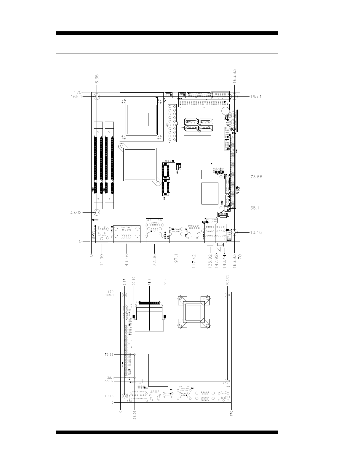
bus. Dimensions of the board are 170mm x 170mm.
The integrated powerful 3D graphics engine, based on Intel® Graphics Media
Accelerator X3500 (Intel® GMA4500MHD) architecture, operates at core
speeds of up to 533 MHz. It features a low-power design, is validated with the
Intel® Core 2 Duo processors on 45nm process. With dual channel DDR2
800MHz two SoDIMM sockets on board, the board supports up to 4GB of
DDR2 system memory.
Intel® Graphics supports a unique intelligent memory management scheme
called Dynamic Video Memory Technology (DVMT). DVMT handles diverse
applications by providing the maximum (384MB) availability of system memory
for general computer usage, while supplying additional graphics memory when a
3D-intensive application requests it. The Intel GMA4500MHD graphics
architecture also takes advantage of the high-performance Intel processor. Intel
GMA4500MHD graphics supports Dual Independent Display technology.
The main features of the board are:
Supports Intel® CoreTM 2 Duo (Penryn 1066MHz)
Supports up to 2.53GHz, 1066MHz/800MHz FSB
Two DDR2 SoDIMM, Max. 4GB memory
Onboard Gigabit PHY and Intel PCI-Express Gigabit LAN
Intel® GM45 Express VGA for CRT / LVDS
4x SATA, 8x USB 2.0, 4x COM, Watchdog timer
1x Mini PCI-E (Mini Card), 1x PCI, 1xPCI-E(x1) slots
Optional daughter cards:
ID390: Chrontel 7308, supports 24 bit single or dual LVDS channel
ID390C: Chrontel 7021, supports CRT
ID391: Chrontel 7307C, single DVI (connector on cable)
ID391D: Chrontel 7307C, dual DVI (connector on cable)
ID392D: Chrontel 7307C, dual DVI (one connector on card and one on cable)
Page 6

INTRODUCTION
2
MI945AF User’s Manual
Checklist
Your MI945 package should include the items listed below.
The MI945 Mini-ITX motherboard
This User’s Manual
1 CD containing chipset drivers and flash memory utility
Cable kit (IDE, Serial port, Serial ATA)
Page 7

INTRODUCTION
MI945AF User’s Manual 3
MI945 Specifications
CPU Supported
Intel® CoreTM 2 Duo (Penryn), mobile processors
CPU Voltage
0.700V ~ 1.5V (IMVP-6)
System Speed
Up to 2.53GHz or above
CPU FSB
667MHz/800MHz/1066MHz FSB
Cache
1MB/2MB/4MB
Green /APM
APM1.2
CPU Socket
mPGA Socket 478
Chipset
Intel GM45 Chipset
GMCH: GM45 1329-pin Micro-FCBGA
ICH9M: 82801IBM 678-pin mBGA
BIOS
Award BIOS, supports ACPI function
Memory
DDR2 667/800 SoDIMM x2 (w/o ECC function), Max. 4GB
VGA
GM45 built-in, supports CRT
SDVO (Dual CH)
Through ID390 card (Chrontel 7308, 24+24 bits single/dual channel
LVDS, Chrontel 7021, CRT)
Through ID391 card (Chrontel 7307C, DVI single or Dual)
LVDS LCD Panel
GM45 built-in, supports 24-bit, single or dual channel LVDS
LAN
1. ICH9M 10/100/gigabit MAC + PHY
Intel 82567L 10/100/1000
2. Intell 82574L PCI-e Gigabit LAN controller x1 (MI945AF)
USB
ICH9M built-in USB 2.0 host controller, support 8 ports
Serial ATA Ports
ICH9M built-in SATA controller, supports 4 ports
Parallel IDE
JMicron JM368 (PCI-e to PATA) x1 for 1 PATA channel for IDE & CF
Audio
ICH9M built-in audio controller + AC97 Codec ALC888 w/ 7.1
channels, SPDIF-OUT
LPC I/O
W83627DHG: COM1, COM2 (RS232/RS422/RS485), hardware
monitor (3 thermal, 4 voltage monitor inputs, 2 fan headers)
- Fintek 81216G for COM3 and COM4
Digital IO
4 in & 4 out
Keyboard/Mouse
Supports PS/2 keyboard/mouse connector
Expansion Slots
PCI slot x1, PIC-E (x1) slot x1 and Mini PCIE socket x1
AMT
PCI slot x1, PIC-E (x1) slot x1 and Mini PCIE socket x1
Edge Connector
PS/2 connector x1 for keyboard/mouse
Gigabit LAN RJ-45 + dual USB stack connector
Gigabit LAN RJ45
Dual USB stack connector
DB9 x1 for COM 1; DB15 x1 for VGA
RCA Jack 3x2 for Audio (Front-Out, Line-In, Mic, Center/LFE,
Surround & Surround Back)
Onboard Header/
Connector
40 pins box-header x1 for IDE1
CF connector x1 @ solder side
10-pin headerx1 for Digital I/O; 10-pin header x1 for COM2
10-pin header x 2 for USB 5,6;7,8
DF13 connector x2 for LVDS;
10-pin header x1 for audio Line-Out & Mic
4-pin header x1 for CD in, SPDIF-out connector x1
SATA connector x4 for SATA ports
Watchdog Timer
Yes (256 segments, 0, 1, 2…255 sec/min)
System Voltage
+5V, +3.3V, +12V, -12V, 5VSB (2A)
Others
Modem Wakeup, LAN Wakeup
Board Size
170mm x 170mm (Mini ITX)
Page 8
INTRODUCTION
4
MI945AF User’s Manual
[
Board Dimensions
Page 9

INSTALLATIONS
MI945AF User’s Manual 5
Installations
This section provides information on how to use the jumpers and
connectors on the MI945 in order to set up a workable system. The topics
covered are:
Installing the CPU .................................................................................. 6
Installing the Memory ............................................................................ 7
Setting the Jumpers ................................................................................ 8
Connectors on MI945 .......................................................................... 12
Page 10
INSTALLATIONS
6
MI945AF User’s Manual
Installing the CPU
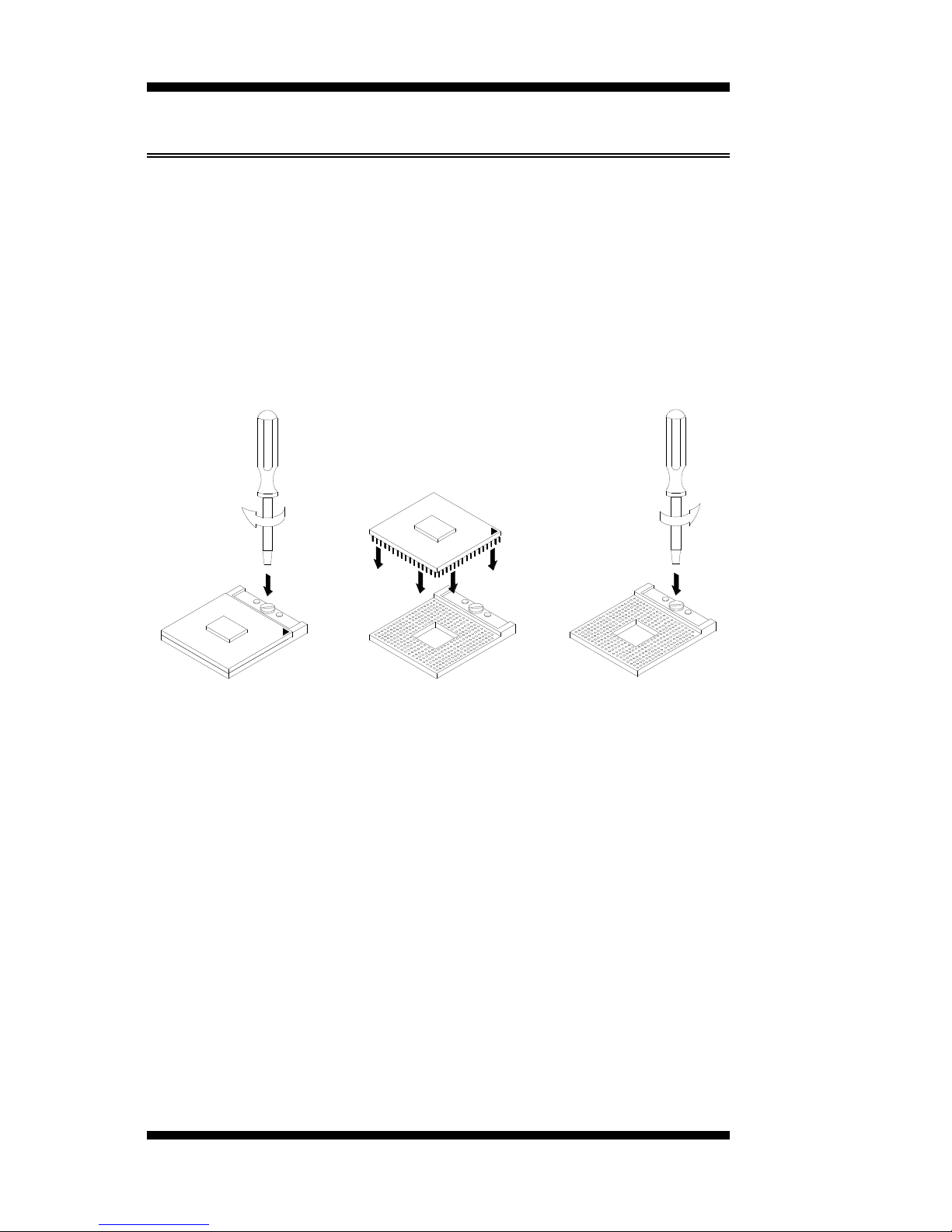
The MI910 board supports a Socket 478MN (Merom) processor socket
for Intel® CoreTM 2 Duo, Intel® Celeron mobile processors.
The processor socket comes with a screw to secure the processor. As
shown in the left picture below, loosen the screw first before inserting the
processor. Place the processor into the socket by making sure the notch
on the corner of the CPU corresponds with the notch on the inside of the
socket. Once the processor has slide into the socket, fasten the screw.
Refer to the figures below.
NOTE:
Ensure that the CPU heat sink and the CPU top surface are in
total contact to avoid CPU overheating problem that would
cause your system to hang or be unstable.
Page 11
INSTALLATIONS
MI945AF User’s Manual 7
Installing the Memory
The MI945 board supports two DDR2 memory socket for a maximum
total memory of 4GB in DDR2 memory type.
Installing and Removing Memory Modules
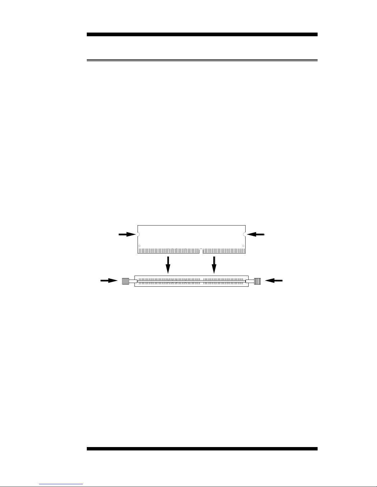
To install the DDR2 modules, locate the memory slot on the board and
perform the following steps:
1. Hold the DDR2 module so that the key of the DDR2 module aligned
with that on the memory slot.
2. Gently push the DDR2 module in an upright position until the clips of
the slot close to hold the DDR2 module in place when the DDR2
module touches the bottom of the slot.
3. To remove the DDR2 module, press the clips with both hands.
DDR2 Module
Lock Lock
Lock Lock
Page 12

INSTALLATIONS
8
MI945AF User’s Manual
Setting the Jumpers
Jumpers are used on MI945 to select various settings and features
according to your needs and applications. Contact your supplier if you
have doubts about the best configuration for your needs. The following
lists the connectors on MI945 and their respective functions.
Jumper Locations on MI945 .................................................................. 9
JP1: Keyboard/Mouse Power Selection ............................................... 10
JP2: LCD Panel Power Selection ......................................................... 10
JP5, JP6, JP7: RS232/422/485 (COM2) Selection .............................. 10
JP9: CompactFlash Slave/Master Selection ......................................... 11
JP10: PCI/PCIE Riser Card Selection .................................................. 11
JBAT1: Clear CMOS Setting ............................................................... 11
IMPORTANT NOTE: When the system boots without the CRT being
connected, there will be no image on screen when you insert the
CRT/VGA cable. To show the image on screen, the hotkey must be
pressed.
Page 13
INSTALLATIONS
MI945AF User’s Manual 9
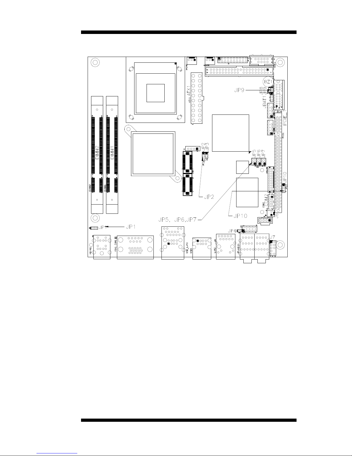
Jumper Locations on MI945
Jumpers on MI945 ............................................................................ Page
JP1: Keyboard/Mouse Power Selection ............................................... 10
JP2: LCD Panel Power Selection ......................................................... 10
JP5, JP6, JP7: RS232/422/485 (COM2) Selection .............................. 10
JP9: CompactFlash Slave/Master Selection ......................................... 11
JP10: PCI/PCIE Riser Card Selection ................................................. 11
JBAT1: Clear CMOS Setting .............................................................. 11
Page 14
INSTALLATIONS
10
MI945AF User’s Manual
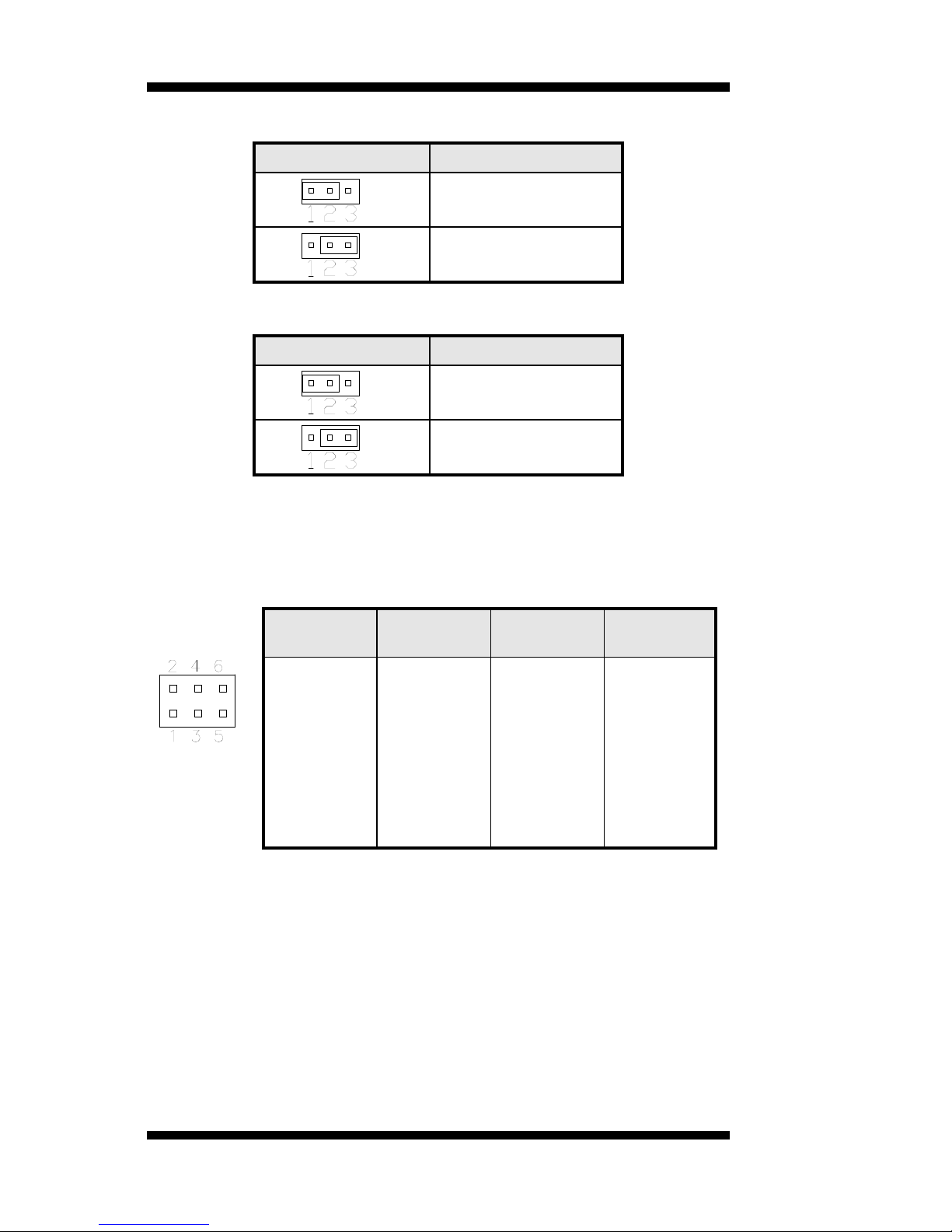
JP1: Keyboard/Mouse Power Selection
JP1
KB/MS Power
5V
5VSB(Standby)
JP2: LCD Panel Power Selection
JP2
LCD Panel Power
3.3V
5V
JP5, JP6, JP7: RS232/422/485 (COM2) Selection
COM1 is fixed for RS-232 use only.
COM2 is selectable for RS232, RS-422 and RS-485.
The following table describes the jumper settings for COM2 selection.
COM2
Function
RS-232
RS-422
RS-485
Jumper
Setting
(pin closed)
JP5:
1-2
JP6:
3-5 & 4-6
JP7:
3-5 & 4-6
JP5:
3-4
JP6:
1-3 & 2-4
JP7:
1-3 & 2-4
JP5:
5-6
JP6:
1-3 & 2-4
JP7:
1-3 & 2-4
Page 15
INSTALLATIONS
MI945AF User’s Manual 11
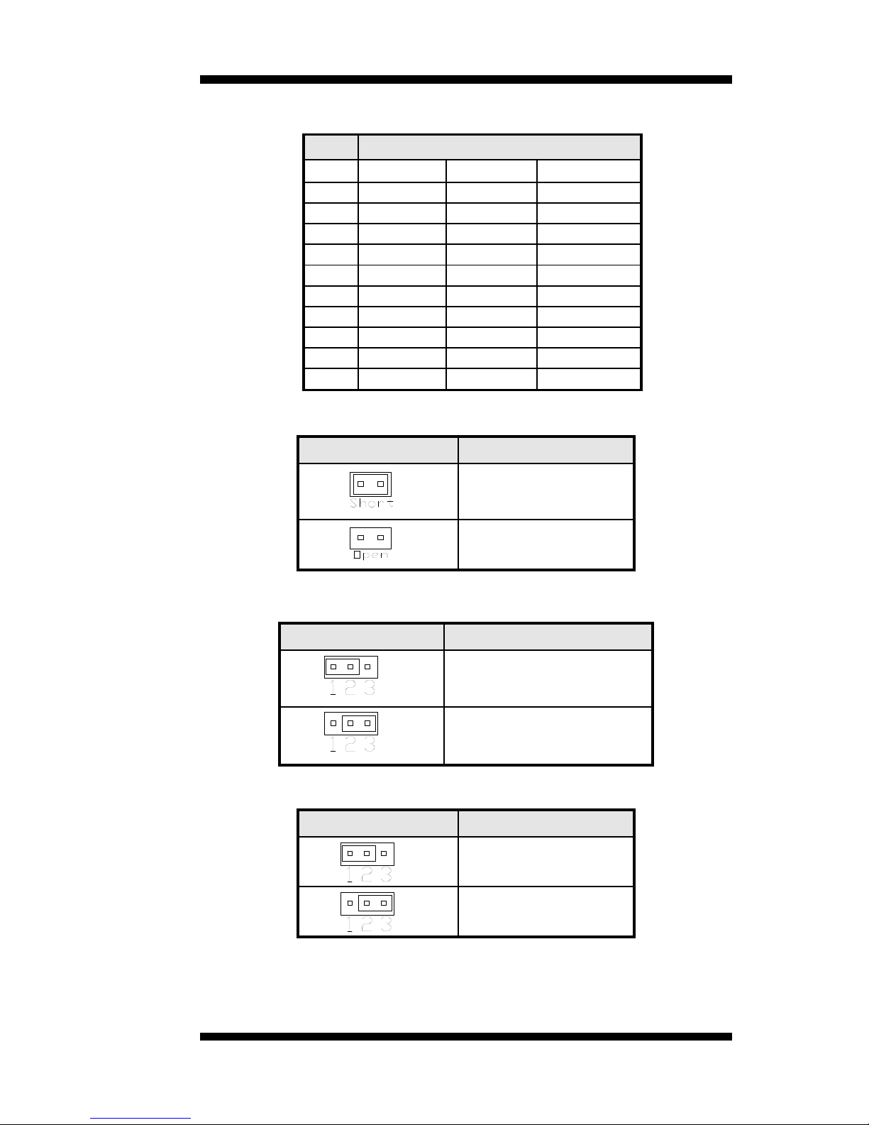
COM2 is jumper selectable for RS-232, RS-422 and RS-485.
Pin #
Signal Name
RS-232
R2-422
RS-485
1
DCD
TX-
DATA-
2
RX
TX+
DATA+
3
TX
RX+
NC
4
DTR
RX-
NC
5
Ground
Ground
Ground
6
DSR
RTS-
NC
7
RTS
RTS+
NC
8
CTS
CTS+
NC
9
RI
CTS-
NC
10
NC
NC
NC
JP9: CompactFlash Slave/Master Selection
JP9
CF Setting
Master
Slave
[
JP10: PCI/PCIE Riser Card Selection
JP10
Riser Card
IP390 Riser Card
Install
IP151, IP240 Riser Card
Install
JBAT1: Clear CMOS Setting
JBAT1
Setting
Normal
Clear CMOS
Page 16

INSTALLATIONS
12
MI945AF User’s Manual
Connectors on MI945
Connector Locations on MI945 ........................................................... 13
CN1: PS/2 Keyboard and PS/2 Mouse Connectors.............................. 14
CN2, CN3: COM1 and VGA Connector ............................................. 14
USB_LAN1: 10/100/1000 RJ-45 (MI945) and USB1/2 Ports
CN4: GbE RJ-45 (MI945AF) .............................................................. 15
USB1: USB3/4 Ports ........................................................................... 15
J6: SPDIF Out Connector .................................................................... 15
CN5: Audio Connector ........................................................................ 15
SYS_FAN1: System Fan Power Connector ......................................... 15
CPU_FAN1: CPU Fan Power Connector ............................................ 15
IDE1: IDE Connector .......................................................................... 16
COM3_COM4: COM3, COM4 Serial Port ......................................... 16
ATX1: ATX Power Supply Connector ................................................ 17
J2 (F_PANEL): System Function Connector ................................ ....... 17
F_USB1: USB5/USB6 Connector ....................................................... 19
COM2: COM2 Serial Port ................................................................... 19
LVDS1, LVDS2: LVDS Connectors (1st channel, 2nd channel) ......... 19
J1: LCD Backlight Connector .............................................................. 20
JMINI: Mini PCIE Connector .............................................................. 20
SATA1, SATA2, SATA3, SATA4: SATA Connectors ....................... 20
J3: Digital I/O ...................................................................................... 20
J5: CD-In Pin Header ........................................................................... 20
J4: SPI Flash Connector (factory use only) .......................................... 20
J7: Front Audio Connector ................................................................... 20
J8: PCI-E(x1) Slot ................................................................................ 20
F_USB2: USB7/USB8 Connector ....................................................... 21
J9: Compact Flash Connector .............................................................. 21
PCI1: PCI Slot (supports 2 Master) ..................................................... 21
CON1: SDVO Port Connector ............................................................. 21
Headers and Connectors on MI910 Daughter Cards ............................ 22
ID390 – JP4 LCD Panel Power Selection ................................ 22
ID390 – J1 LCD Backlight Setting ......................................... 22
ID390 – J3 and J2 1st/2
nd
LVDS Channel Connectors ............... 22
Page 17
INSTALLATIONS
MI945AF User’s Manual 13
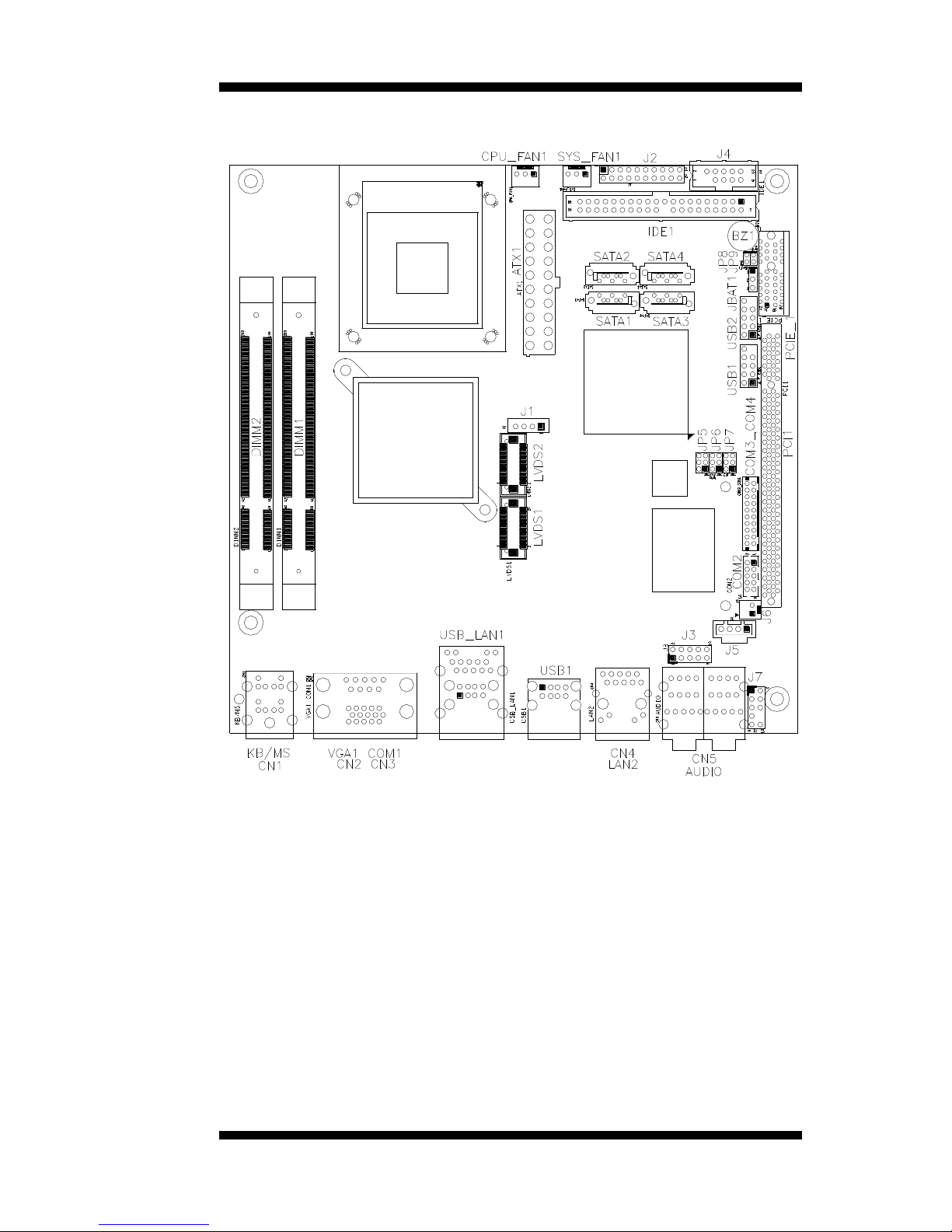
Connector Locations on MI945
Page 18
INSTALLATIONS
14
MI945AF User’s Manual
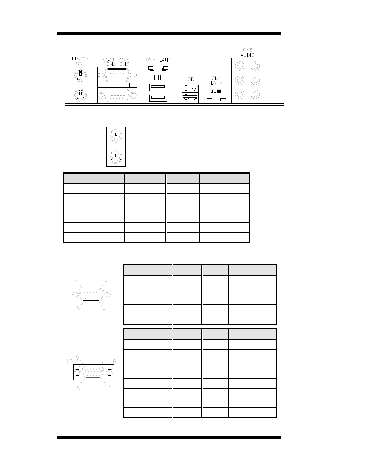
CN1: PS/2 Keyboard and PS/2 Mouse Connectors
PS/2 Mouse
PS/2 Keyboard
Signal Name
Keyboard
Mouse
Signal Name
Keyboard data
1
1
Mouse data
N.C.
2 2 N.C.
GND
3 3 GND
5V
4 4 5V
Keyboard clock
5
5
Mouse clock
N.C.
6 6 N.C.
CN2, CN3: COM1 and VGA Connector
[
Signal Name
Pin #
Pin #
Signal Name
DCD
1 6 DSR
RXD
2 7 RTS
TXD
3 8 CTS
DTR
4 9 RI
GND
5
10
Not Used
[[[[
Signal Name
Pin #
Pin #
Signal Name
Red
1 2 Green
Blue
3 4 N.C.
GND
5 6 GND
GND
7 8 GND
N.C.
9
10
GND
N.C.
11
12
N.C.
HSYNC
13
14
VSYNC
NC
15
Page 19
INSTALLATIONS
MI945AF User’s Manual 15
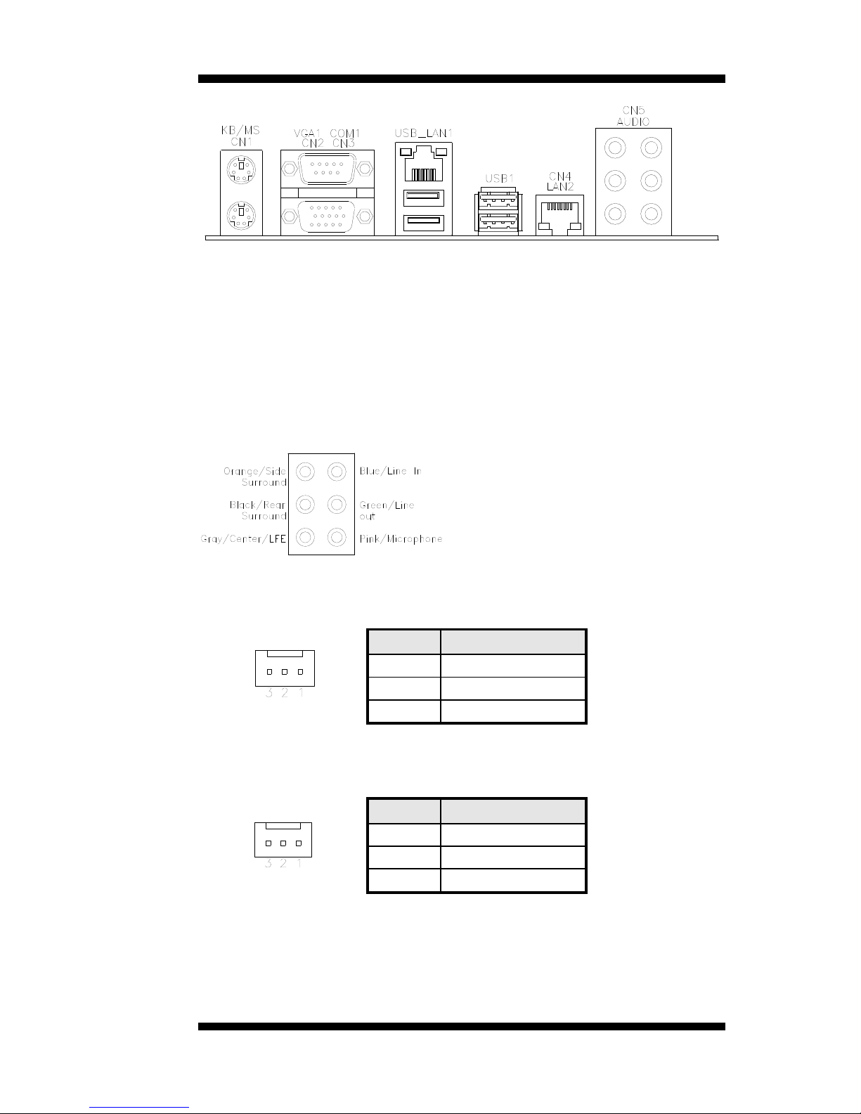
USB_LAN1: 10/100/1000 RJ-45 (MI945) and USB1/2 Ports
CN4: GbE RJ-45 (MI945AF)
USB1: USB3/4 Ports
J6: SPDIF Out Connector
CN5: Audio Connector
SYS_FAN1: System Fan Power Connector
This is a 3-pin header for system fans. The fan must be a 12V (500mA).
Pin #
Signal Name
1
Ground
2
+12V
3
Rotation detection
CPU_FAN1: CPU Fan Power Connector
This is a 3-pin header for the CPU fan. The fan must be a 12V fan.
Pin #
Signal Name
1
Ground
2
+12V
3
Rotation detection
Page 20
INSTALLATIONS
16
MI945AF User’s Manual
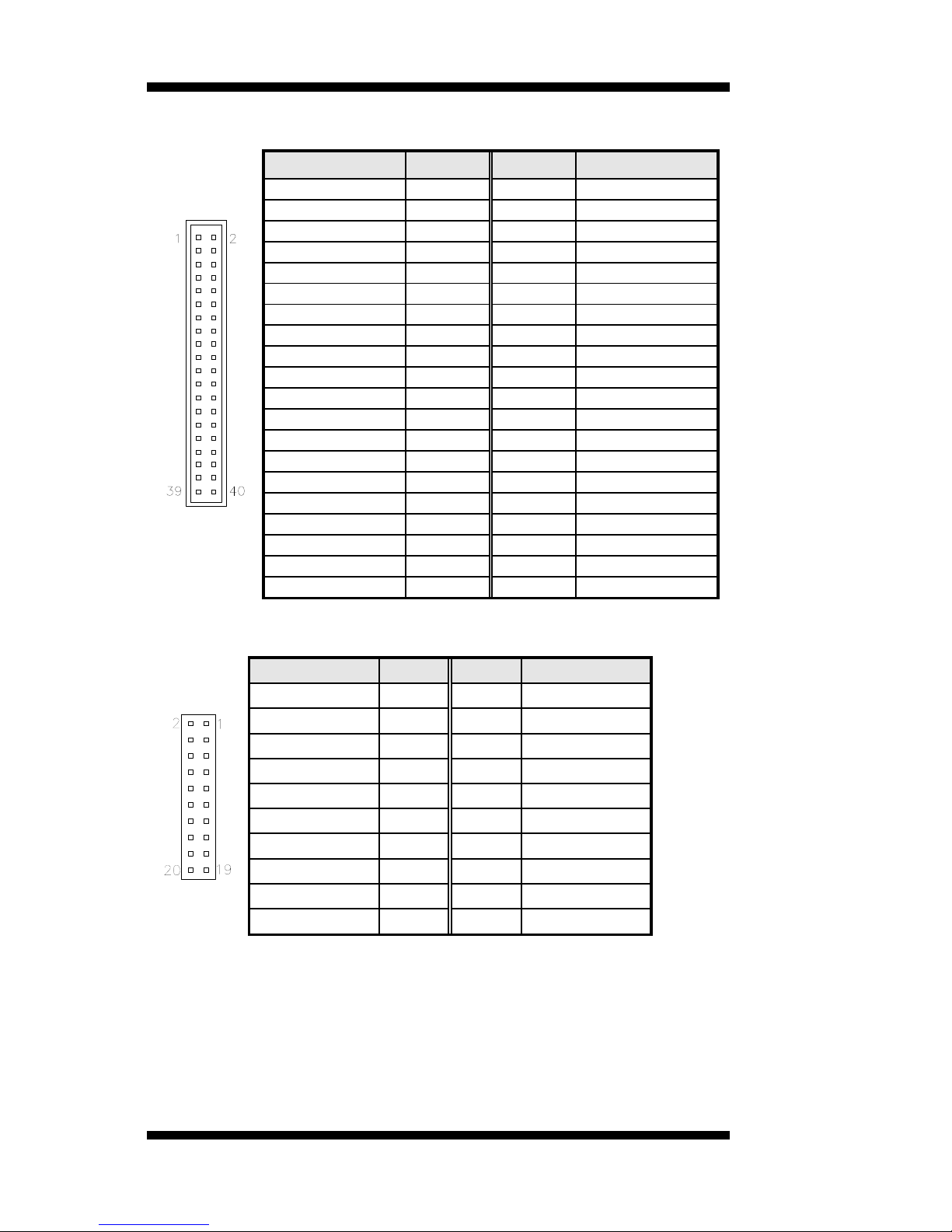
IDE1: IDE Connector
Signal Name
Pin #
Pin #
Signal Name
Reset IDE
1 2 Ground
Host data 7
3 4 Host data 8
Host data 6
5 6 Host data 9
Host data 5
7
8
Host data 10
Host data 4
9
10
Host data 11
Host data 3
11
12
Host data 12
Host data 2
13
14
Host data 13
Host data 1
15
16
Host data 14
Host data 0
17
18
Host data 15
Ground
19
20
Protect pin
DRQ0
21
22
Ground
Host IOW
23
24
Ground
Host IOR
25
26
Ground
IOCHRDY
27
28
Host ALE
DACK0
29
30
Ground
IRQ14
31
32
No connect
Address 1
33
34
No connect
Address 0
35
36
Address 2
Chip select 0
37
38
Chip select 1
Activity
39
40
Ground
COM3_COM4: COM3, COM4 Serial Port
Signal Name
Pin #
Pin #
Signal Name
DSR
2 1 DCD
RTS
4 3 RXD
CTS
6 5 TXD
RI
8 7 DTR
NA
10 9 Ground
DSR
12
11
DCD
RTS
14
13
RXD
CTS
16
15
TXD
RI
18
17
DTR
NA
20
19
Ground
Page 21
INSTALLATIONS
MI945AF User’s Manual 17
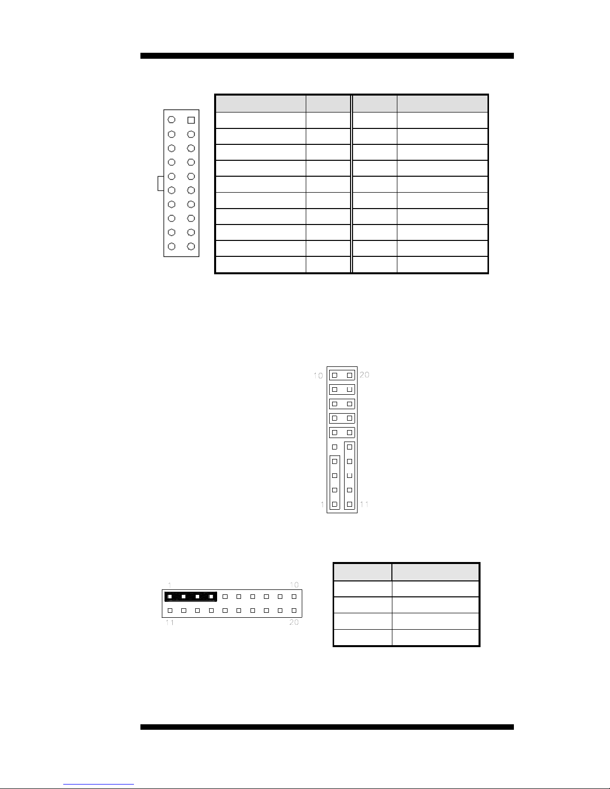
ATX1: ATX Power Supply Connector
11 1
20 10
Signal Name
Pin #
Pin #
Signal Name
3.3V
11 1 3.3V
-12V
12 2 3.3V
Ground
13 3 Ground
PS-ON
14 4 +5V
Ground
15 5 Ground
Ground
16 6 +5V
Ground
17 7 Ground
-5V
18 8 Power good
+5V
19 9 5VSB
+5V
20
10
+12V
J2 (F_PANEL): System Function Connector
J2 provides connectors for system indicators that provide light indication
of the computer activities and switches to change the computer status. J2
is a 20-pin header that provides interfaces for the following functions.
Hard Disk Drive LED
Reset Switch
Not Defined
ATX Power On Switch
Not Defined
Power LED
Speaker
Speaker: Pins 1 - 4
This connector provides an interface to a speaker for audio
tone generation. An 8-ohm speaker is recommended.
Pin #
Signal Name
1
Speaker out
2
No connect
3
Ground
4
+5V
Page 22
INSTALLATIONS
18
MI945AF User’s Manual
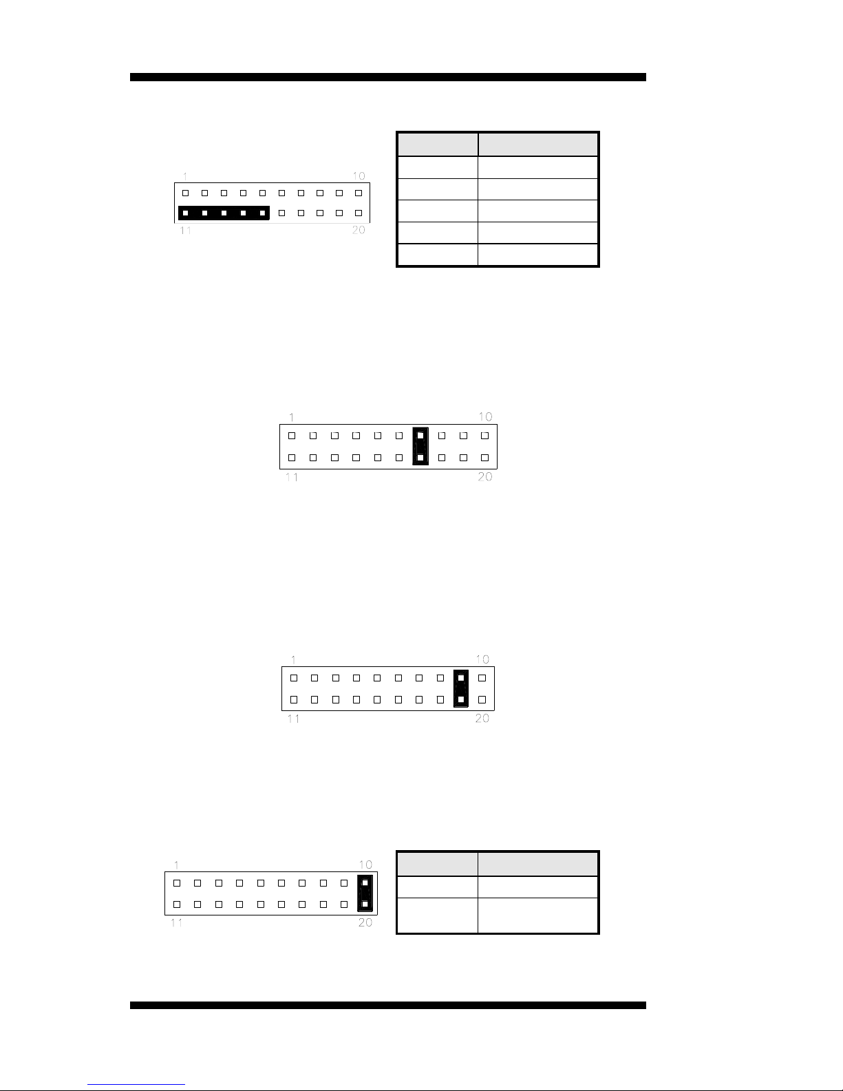
Power LED: Pins 11 - 15
Pin #
Signal Name
11
Power LED
12
No connect
13
Ground
14
No connect
15
Ground
ATX Power ON Switch: Pins 7 and 17
This 2-pin connector is an “ATX Power Supply On/Off
Switch” on the system that connects to the power switch on
the case. When pressed, the power switch will force the
system to power on. When pressed again, it will force the
system to power off.
Reset Switch: Pins 9 and 19
The reset switch allows the user to reset the system without
turning the main power switch off and then on again.
Orientation is not required when making a connection to this
header.
Hard Disk Drive LED Connector: Pins 10 and 20
This connector connects to the hard drive activity LED on
control panel. This LED will flash when the HDD is being
accessed.
Pin #
Signal Name
10
HDD Active
20
5V
Page 23
INSTALLATIONS
MI945AF User’s Manual 19
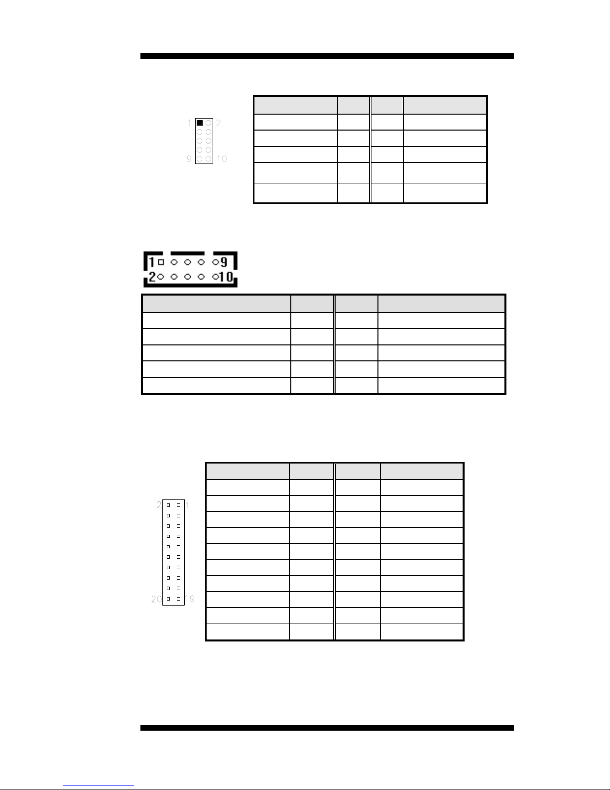
F_USB1: USB5/USB6 Connector
Signal Name
Pin
Pin
Signal Name
Vcc
1 2 Vcc
D0-
3 4 D1-
D0+
5 6 D1+
Ground
7 8 Ground
NC
9
10
Ground
COM2: COM2 Serial Port
Signal Name
Pin #
Pin #
Signal Name
DCD, Data carrier detect
1 6 DSR, Data set ready
RXD, Receive data
2 7 RTS, Request to send
TXD, Transmit data
3 8 CTS, Clear to send
DTR, Data terminal ready
4 9 RI, Ring indicator
GND, ground
5
10
Not Used
LVDS1, LVDS2: LVDS Connectors (1st channel, 2nd channel)
The LVDS connectors on board consist of the first channel (LVDS1) and
second channel (LVDS2).
Signal Name
Pin #
Pin #
Signal Name
TX0-
2 1 TX0+
Ground
4 3 Ground
TX1-
6 5 TX1+
5V/3.3V
8 7 Ground
TX3-
10 9 TX3+
TX2-
12
11
TX2+
Ground
14
13
Ground
TXC-
16
15
TXC+
5V/3.3V
18
17
ENABKL
+12V
20
19
+12V
Page 24
INSTALLATIONS
20
MI945AF User’s Manual
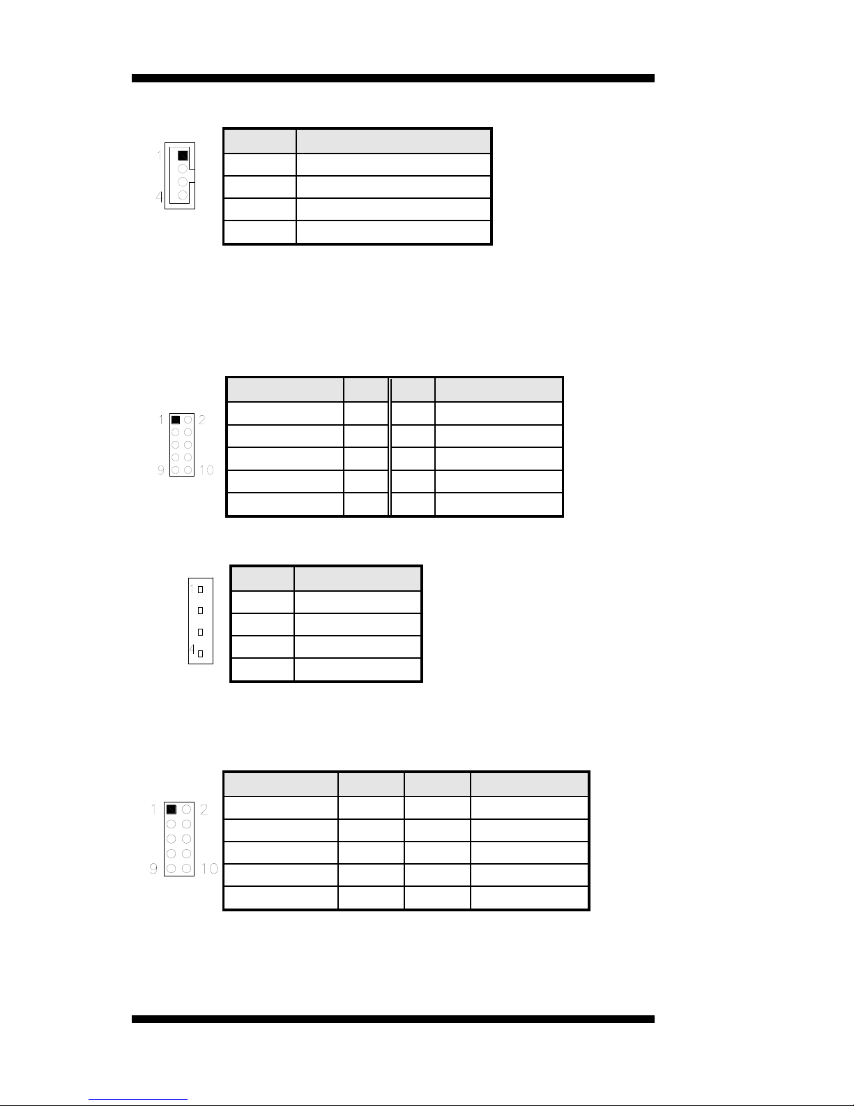
J1: LCD Backlight Connector
Pin #
Signal Name
1
+12V
2
Backlight Enable
3
Brightness Control
4
Ground
JMINI: Mini PCIE Connector
SATA1, SATA2, SATA3, SATA4: SATA Connectors
J3: Digital I/O
Signal Name
Pin
Pin
Signal Name
GND
1 2 VCC
OUT3
3 4 OUT1
OUT2
5 6 OUT0
IN3
7 8 IN1
IN2
9
10
IN0
J5: CD-In Pin Header
Pin #
Signal Name
1
CD Audio R
2
Ground
3
Ground
4
CD Audio L
J4: SPI Flash Connector (factory use only)
J7: Front Audio Connector
Signal Name
Pin #
Pin #
Signal Name
MIC2_L
1 2 Ground
MIC2_R
3 4 Presence#
Line2_L
5 6 MIC2_ID
Sense
7 8 NC
Line2_R
9
10
Line2_ID
J8: PCI-E(x1) Slot
Page 25

INSTALLATIONS
MI945AF User’s Manual 21
F_USB2: USB7/USB8 Connector
Signal Name
Pin
Pin
Signal Name
Vcc
1 2 Vcc
D0-
3 4 D1-
D0+
5 6 D1+
Ground
7 8 Ground
NC
9
10
Ground
J9: Compact Flash Connector
PCI1: PCI Slot (supports 2 Master)
CON1: SDVO Port Connector
Signal Name
Pin #
Pin #
Signal Name
+12V
A1
B1
+12V
+12V
A2
B2
+12V
+5V
A3
B3
+5V
3.3V
A4
B4
3.3V
RESET
A5
B5
GND
GND
A6
B6
GND
SDVOC_CLK+
A7
B7
SDVOC_CLK-
SDVOC_Blue+
A8
B8
SDVOC_Blue-
GND
A9
B9
GND
SDVOC_Green+
A10
B10
SDVOC_Green-
SDVOC_Red+
A11
B11
SDVOC_Red-
GND
A12
B12
GND
SDVO TVClkIn+
A13
B13
SDVO TVClkIn-
SDVOB Int+
A14
B14
SDVOB Int-
GND
A15
B15
GND
SDVO CtrlData
A16
B16
SDVO CtrlClk
SDVOB Clk+
A17
B17
SDVOB Clk-
GND
A18
B18
GND
SDVOB Blue+
A19
B19
SDVOB Blue-
SDVOB Green+
A20
B20
SDVOB Green-
GND
A21
B21
GND
SDVOB Red+
A22
B22
SDVOB Red-
SDVO Stall+
A23
B23
SDVO Stall-
GND
A24
B24
GND
Page 26
INSTALLATIONS
22
MI945AF User’s Manual
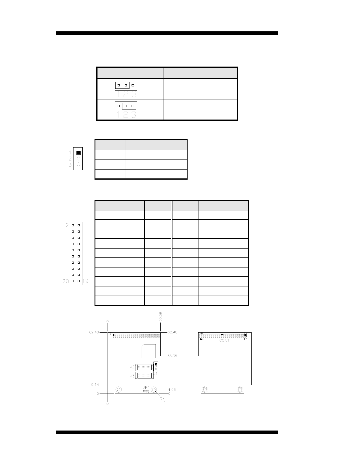
Headers and Connectors on MI910 Daughter Cards
ID390 – JP4 LCD Panel Power Selection
JP4
Voltage
3.3V
5V
ID390 – J1 LCD Backlight Setting
Pin #
Signal Name
1
+12V
2
Backlight Enable
3
Ground
ID390 – J3 and J2 1st/2nd LVDS Channel Connectors
Signal Name
Pin #
Pin #
Signal Name
TX0-
2 1 TX0+
Ground
4 3 Ground
TX1-
6 5 TX1+
5V/3.3V
8 7 Ground
TX3-
10 9 TX3+
TX2-
12
11
TX2+
Ground
14
13
Ground
TXC-
16
15
TXC+
5V/3.3V
18
17
ENABKL
+12V
20
19
+12V
Page 27

BIOS SETUP
MI945AF User’s Manual 23
BIOS Setup
This chapter describes the different settings available in the Award BIOS
that comes with the board. The topics covered in this chapter are as
follows:
BIOS Introduction ........................................................................................ 24
BIOS Setup .................................................................................................... 24
Main BIOS Setup .......................................................................................... 25
Advanced Settings ........................................................................................ 26
PCIPnP Settings ............................................................................................ 36
Boot Settings ................................................................................................. 37
Security Settings ........................................................................................... 38
Advanced Chipset Settings .......................................................................... 39
Exit Setup ....................................................................................................... 43
Load Optimal Defaults ................................................................................. 43
Load Failsafe Defaults ................................................................................. 43
Page 28

BIOS SETUP
24
MI945AF User’s Manual
BIOS Introduction
The BIOS (Basic Input/Output System) installed in your computer
system’s ROM supports Intel processors. The BIOS provides critical
low-level support for a standard device such as disk drives, serial ports
and parallel ports. It also adds virus and password protection as well as
special support for detailed fine-tuning of the chipset controlling the
entire system.
BIOS Setup
The BIOS provides a Setup utility program for specifying the system
configurations and settings. The BIOS ROM of the system stores the
Setup utility. When you turn on the computer, the BIOS is immediately
activated. Pressing the <Del> key immediately allows you to enter the
Setup utility. If you are a little bit late pressing the <Del> key, POST
(Power On Self Test) will continue with its test routines, thus preventing
you from invoking the Setup. If you still wish to enter Setup, restart the
system by pressing the ”Reset” button or simultaneously pressing the
<Ctrl>, <Alt> and <Delete> keys. You can also restart by turning the
system Off and back On again. The following message will appear on the
screen:
Press <DEL> to Enter Setup
In general, you press the arrow keys to highlight items, <Enter> to select,
the <PgUp> and <PgDn> keys to change entries, <F1> for help and
<Esc> to quit.
When you enter the Setup utility, the Main Menu screen will appear on
the screen. The Main Menu allows you to select from various setup
functions and exit choices.
Page 29

BIOS SETUP
MI945AF User’s Manual 25
Main BIOS Setup
This setup allows you to record some basic hardware configurations in
your computer system and set the system clock.
BIOS SETUP UTILITY
Main Advanced PCIPnP Boot Security Chipset Exit
Use[ENTER], [TAB]
or [SHIFT-TAB] to
select a field.
Use [+] or [-] to
configure system Time.
<- Select Screen
↑↓ Select Item
+- Change Field
Tab Select Field
F1 General Help
F10 Save and Exit
ESC Exit
Processor
Intel(R) Core(TM)2 Duo CPU
T9400 @ 2.53GHz
Speed : 2533MHz
Count : 1
System Memory
Size : 3995MB
System Time
[02:29:50]
System Date
[Fri 01/02/2009]
Note:
If the system cannot boot after making and saving system
changes with Setup, the Award BIOS supports an override to
the CMOS settings that resets your system to its default.
Warning:
It is strongly recommended that you avoid making any
changes to the chipset defaults. These defaults have been
carefully chosen by both Award and your system
manufacturer to provide the absolute maximum performance
and reliability. Changing the defaults could cause the system
to become unstable and crash in some cases.
Page 30

BIOS SETUP
26
MI945AF User’s Manual
Advanced Settings
This section allows you to configure and improve your system and allows
you to set up some system features according to your preference.
BIOS SETUP UTILITY
Main Advanced PCIPnP Boot Security Chipset Exit
Advanced Settings
Configure CPU.
<- Select Screen
↑↓ Select Item
+- Change Field
Tab Select Field
F1 General Help
F10 Save and Exit
ESC Exit
WARNING: Setting wrong values in below sections
may cause system to malfunction.
► CPU Configurations
► IDE Configuration
► SuperIO Configuration
► Hardware Health Confguration
► Secondary SuperIO Configuration
► ACPI Configuration
► AHCI Configuration
► APM Configuration
► Event Log Configuration
► Intel AMT Configuration
► Intel VT-d Configuration
► MPS Configuration
► USB Configuration
The Advanced BIOS Settings contains the following sections:
► CPU Configurations
► IDE Configuration
► SuperIO Configuration
► Hardware Health Confguration
► Secondary SuperIO Configuration
► ACPI Configuration
► AHCI Configuration
► APM Configuration
► Event Log Configuration
► Intel AMT Configuration
► Intel VT-d Configuration
► MPS Configuration
► USB Configuration
The fields in each section are shown in the following pages, as seen in the
computer screen. Please note that setting the wrong values may cause the system
to malfunction. If unsure, please contact technical support of your supplier.
Page 31

BIOS SETUP
MI945AF User’s Manual 27
BIOS SETUP UTILITY
Main Advanced PCIPnP Boot Security Chipset Exit
Configure advanced CPU settings
Module Version: 3F.15
Configure CPU.
<- Select Screen
↑↓ Select Item
+- Change Field
Tab Select Field
F1 General Help
F10 Save and Exit
ESC Exit
Manufacturer: Intel
Intel® Core(TM)2 Duo CPU
T9400 @ 2.53GHz
Frequency : 2.53GHz
FSB Speed : 1066MHz
Cache L1 : 64KB
Cache L2 : 6144KB
Ratio Actual Value: 9.5
Max CPUID Value Limit
Disabled
Intel(R) Virtualization Tech
Enabled
Execute-Disable Bit Capability
Enabled
Core Multi-Processing
Enabled
Intel(R) SpeedStep(tm) tech
Enabled
The CPU Configuration menu shows the following CPU details:
Manufacturer: the name of the CPU manufacturer
Brand String: the brand name of the CPU being used
Frequency: the CPU processing speed
FSB Speed: the FSB speed
Cache L1: the CPU L1 cache size
Cache L2: the CPU L2 cache
Page 32

BIOS SETUP
28
MI945AF User’s Manual
BIOS SETUP UTILITY
Main Advanced PCIPnP Boot Security Chipset Exit
IDE Configuration
Options:
Disabled
Compatible
Enhanced
<- Select Screen
↑↓ Select Item
+- Change Field
Tab Select Field
F1 General Help
F10 Save and Exit
ESC Exit
Mirrored IDER Configuration
[Enabled]
SATA#1 Configuration
[Compatible]
Configure SATA#1 as
[IDE]
SATA#2 Configuration
► Primary IDE Master
: [Not Detected]
► Primary Slave Master
: [Not Detected]
► Secondary IDE Master
: [Hitachi HDS72]
► Secondary IDE Slave
: [Not Detected]
► Third IDE Master
: [Not Detected]
► Fourth IDE Master
: [Not Detected]
► Primary IDE Master
: [Not Detected]
► Fifth IDE Master
: [Not Detected]
► Fifth IDE Slave
IDE Detect Time Out (Sec)
ATA(PI) 80Pin Cable Detection
: [Not Detected]
[35]
[Host & Device]
The IDE Configuration menu is used to change and/or set the
configuration of the IDE devices installed in the system. SATA#1 can be
configured as IDE, Raid or AHCI.
BIOS SETUP UTILITY
Main Advanced PCIPnP Boot Security Chipset Exit
Hardware Health Configuration
Configure CPU.
<- Select Screen
↑↓ Select Item
+- Change Field
Tab Select Field
F1 General Help
F10 Save and Exit
ESC Exit
System Temperature
:45°C/113°F
CPU Temperature
:45°C/113°F
Chassi Temperature
:33°C/102°F
SYSTEM Speed
:0 RPM
CPUFAN Speed
:5400 RPM
Vcore(V)
:1.160 V
AVCC
:3.392 V
3VCC
12V
:3.392 V
:12.196 V
1.8V
:1.856 V
5V
: 5.273V
VSB
: 3.392V
VBAT (V)
:3.21 V
ACPI Shut down Temperature
95°C/203°F
The Hardware Health Configuration menu is used to show the operating
temperature, fan speeds and system voltages.
Page 33

BIOS SETUP
MI945AF User’s Manual 29
BIOS SETUP UTILITY
Main Advanced PCIPnP Boot Security Chipset Exit
Configure Win627DHG Super IO Chipset
<- Select Screen
↑↓ Select Item
+- Change Field
Tab Select Field
F1 General Help
F10 Save and Exit
ESC Exit
Serial Port1 Address
[3F8/IRQ4]
Serial Port2 Address
[Disabled]
Configure SATA#1 as
[Disabled]
Parallel Port Address
[Disabled]
Restore on AC Power Loss
[Power Off]
Power On Function
[None]
Main Advanced PCIPnP Boot Security Chipset Exit
<- Select Screen
↑↓ Select Item
+- Change Field
Tab Select Field
F1 General Help
F10 Save and Exit
ESC Exit
Serial Port3 Address
[Disabled]
Serial Port4 Address
[Disabled]
Onboard Serial Port/Parallel Port
These fields allow you to select the onboard serial ports and their
addresses. The default values for these ports are:
Serial Port 1 3F8/IRQ4
Serial Port 2 Disabled
Serial Port 3 Disabled
Serial Port 4 Disabled
Page 34

BIOS SETUP
30
MI945AF User’s Manual
Restore on AC Power Loss
This field sets the system power status whether on or off when power
returns to the system from a power failure situation.
Power On Function
This field is related to how the system is powered on . The options are
None, Mouse Left, Mouse Right, and Any Key.
BIOS SETUP UTILITY
Main Advanced PCIPnP Boot Security Chipset Exit
ACPI Settings
General ACPI
Configuration settings
<- Select Screen
↑↓ Select Item
+- Change Field
Tab Select Field
F1 General Help
F10 Save and Exit
ESC Exit
►General ACPI Configuration
►Chipset ACPI Configuration
BIOS SETUP UTILITY
Main Advanced PCIPnP Boot Security Chipset Exit
General ACPI Configuration
General ACPI
Configuration settings
<- Select Screen
↑↓ Select Item
+- Change Field
Tab Select Field
F1 General Help
F10 Save and Exit
ESC Exit
Suspend mode
[Auto]
Repost Video on S3 Resume
[No]
Suspend Mode
The options of this field are S1, S3 and Auto.
Page 35

BIOS SETUP
MI945AF User’s Manual 31
BIOS SETUP UTILITY
Main Advanced PCIPnP Boot Security Chipset Exit
South Bridge ACPI Configuration
General ACPI
Configuration settings
<- Select Screen
↑↓ Select Item
+- Change Field
Tab Select Field
F1 General Help
F10 Save and Exit
ESC Exit
High Performance Event Timer
[Enabled]
HPET Memory Address
[FED00000h]
BIOS SETUP UTILITY
Main Advanced PCIPnP Boot Security Chipset Exit
AHCI Settings
AHCI BIOS Support [Enabled]
General ACPI
Configuration settings
<- Select Screen
↑↓ Select Item
+- Change Field
Tab Select Field
F1 General Help
F10 Save and Exit
ESC Exit
► AHCI Port0 [Not Detected]
► AHCI Port1 [Not Detected]
► AHCI Port2 [Not Detected]
► AHCI Port3 [Not Detected]
► AHCI Port4 [Not Detected]
► AHCI Port5 [Not Detected]
BIOS SETUP UTILITY
Main Advanced PCIPnP Boot Security Chipset Exit
APM Configuration
Disable/Enable
RI to generate
a wake event.
<- Select Screen
↑↓ Select Item
+- Change Field
Tab Select Field
F1 General Help
F10 Save and Exit
ESC Exit
Resume On Ring
Disabled
Resume On PME#
Disabled
Resume On RTC Alarm
Disabled
Page 36

BIOS SETUP
32
MI945AF User’s Manual
Resume on Ring
This option is used to enable activity on the RI (ring in) modem line to
wake up the system from a suspend or standby state. That is, the system
will be awakened by an incoming call on a modem.
Resume on PME#
This option is used enable activity on the PCI PME (power
managementevent) controller to wake up the system from a suspend or
standby state
Resume On RTC Alarm
This option is used to specify the time the system should be awakened
from a suspended state
Page 37

BIOS SETUP
MI945AF User’s Manual 33
BIOS SETUP UTILITY
Main Advanced PCIPnP Boot Security Chipset Exit
Event Logging details
View all unread events
on the Event Log. CPU.
<- Select Screen
↑↓ Select Item
+- Change Field
Tab Select Field
F1 General Help
F10 Save and Exit
ESC Exit
View Event Log
Mark all events as read
Clear Event Log
BIOS SETUP UTILITY
Main Advanced PCIPnP Boot Security Chipset Exit
Configure Intel AMT Parameters
Options:
Disabled
Enabled
<- Select Screen
↑↓ Select Item
+- Change Field
Tab Select Field
F1 General Help
F10 Save and Exit
ESC Exit
Intel AMT Support
[Disabled]
Unconfigure AMT/ME
[Disabled]
The Intel AMT Configuration configures the Intel Active Management
Technology (AMT) options.
Page 38

BIOS SETUP
34
MI945AF User’s Manual
BIOS SETUP UTILITY
Main Advanced PCIPnP Boot Security Chipset Exit
Options:
Disabled
Enabled
<- Select Screen
↑↓ Select Item
+- Change Field
Tab Select Field
F1 General Help
F10 Save and Exit
ESC Exit
Intel VT-d
[Disabled]
VT-d
Virtualization solutions allow multiple operating systems and
applications to run in independent partitions all on a single computer.
Using virtualization capabilities, one physical computer system can
function as multiple "virtual" systems.
BIOS SETUP UTILITY
Main Advanced PCIPnP Boot Security Chipset Exit
MPS Configuration
Select MPS
Revision
<- Select Screen
↑↓ Select Item
+- Change Field
Tab Select Field
F1 General Help
F10 Save and Exit
ESC Exit
MPS Revision VT-d
[1.4]
MPS Version Control for OS
This option is specifies the MPS (Multiprocessor Specification) version
for your operating system. MPS version 1.4 added extended
configuration tables to improve support for multiple PCI bus
configurations and improve future expandability. The default setting is
1.4.
Page 39

BIOS SETUP
MI945AF User’s Manual 35
BIOS SETUP UTILITY
Main Advanced PCIPnP Boot Security Chipset Exit
USB Configuration
Enables support for
legacy USB. AUTO
option disables
legacy support if
no USB devices are
connected.
<- Select Screen
↑↓ Select Item
+- Change Field
Tab Select Field
F1 General Help
F10 Save and Exit
ESC Exit
Module Version – 2.24.3.13.4
USB Devices Enabled:
1 Drive
Legacy USB Support
[Enabled]
BIOS EHCI Hand-Off
[Enabled]
► USB Mass Storage Device Configuration
The USB Configuration menu is used to read USB configuration
information and configure the USB settings.
Legacy USB Support
This option is used to enable the USB mouse and USB keyboard support.
This option is enabled by default.
USB Mass Storage Device Configuration
This option is used to configure USB mass storage class devices.
Page 40

BIOS SETUP
36
MI945AF User’s Manual
PCIPnP Settings
This option configures the PCI/PnP settings.
BIOS SETUP UTILITY
Main Advanced PCIPnP Boot Security Chipset Exit
Advanced PCI/PnP Settings
Size of memory block
to reserve for legacy
ISA devices.
<- Select Screen
↑↓ Select Item
+- Change Field
Tab Select Field
F1 General Help
F10 Save and Exit
ESC Exit
WARNING: Setting wrong values in below sections
may cause system to malfunction.
Clear NVRAM
[No]
Plug & Play O/S
[No]
PCI Latency Timer
[64]
Allocate IRQ to PCI VGA
[Yes]
Palette Snooping
[Disabled]
PCI IDE BusMaster
[Enabled]
IRQ3
[Available]
IRQ4
[Available]
IRQ5
[Available]
IRQ7
[Available]
IRQ9
[Available]
IRQ10
IRQ11
IRQ14
IRQ15
DMA Channel 0
DMA Channel 1
DMA Channel 3
DMA Channel 5
DMA Channel 6
DMA Channel 7
Reserved Memory Size
[Available]
[Available]
[Available]
[Available]
[Available]
[Available]
[Available]
[Available]
[Available]
[Available]
[Disabled]
Clear NVRAM
This item is used for clearing NVRAM during system boot.
Plug & Play O/S
This lets BIOS configure all devices in the system or lets the OS
configure PnP devices not required for boot if your system has a Plug and
Play OS.
PCI Latency Timer
This item sets value in units of PCI clocks for PCI device latency timer
register. Options are: 32, 64, 96, 128, 160, 192, 224, 248.
Page 41

BIOS SETUP
MI945AF User’s Manual 37
Allocate IRQ to PCI VGA
This assigns IRQ to PCI VGA card if card requests IRQ or doesn't assign
IRQ to PCI VGA card even if card requests an IRQ.
Palette Snooping
This informs the PCI devices that an ISA graphics device is installed in
the system so the card will function correctly.
PCI IDE BusMaster
This uses PCI busmastering for BIOS reading / writing to IDE devices.
IRQ#
Use the IRQ# address to specify what IRQs can be assigned to a
particular peripheral device.
Boot Settings
This option configures the settings during system boot including boot
device priority and HDD/CD/DVD drives.
BIOS SETUP UTILITY
Main Advanced PCIPnP Boot Security Chipset Exit
Boot Settings
Configure Settings
during System Boot.
<- Select Screen
↑↓ Select Item
+- Change Field
Tab Select Field
F1 General Help
F10 Save and Exit
ESC Exit
► Boot Settings Configuration
► Boot Device Priority
► Hard Disk Drives
► CD/DVD Drives
Page 42

BIOS SETUP
38
MI945AF User’s Manual
Security Settings
This setting comes with two options set the system password. Supervisor
Password sets a password that will be used to protect the system and
Setup utility. User Password sets a password that will be used exclusively
on the system. To specify a password, highlight the type you want and
press <Enter>. The Enter Password: message prompts on the screen.
Type the password and press <Enter>. The system confirms your
password by asking you to type it again. After setting a password, the
screen automatically returns to the main screen.
To disable a password, just press the <Enter> key when you are prompted
to enter the password. A message will confirm the password to be
disabled. Once the password is disabled, the system will boot and you can
enter Setup freely.
BIOS SETUP UTILITY
Main Advanced PCIPnP Boot Security Chipset Exit
Security Settings
Install or Change the
Password.
<- Select Screen
↑↓ Select Item
+- Change Field
Tab Select Field
F1 General Help
F10 Save and Exit
ESC Exit
Supervisor Password : Not Installed
User Password : Not Installed
Change Supervisor Password
Change User Password
Boot Sector Virus Protection [Disabled]
Page 43

BIOS SETUP
MI945AF User’s Manual 39
Advanced Chipset Settings
This setting configures the north bridge, south bridge and the ME
subsystem. WARNING! Setting the wrong values may cause the system
to malfunction. -
BIOS SETUP UTILITY
Main Advanced PCIPnP Boot Security Chipset Exit
Advanced Chipset Settings
Configure North Bridge
features.
<- Select Screen
↑↓ Select Item
+- Change Field
Tab Select Field
F1 General Help
F10 Save and Exit
ESC Exit
WARNING: Setting wrong values in below sections
may cause system to malfunction.
► North Bridge Configuration
► South Bridge Configuration
► ME Subsystem Configuration
BIOS SETUP UTILITY
Main Advanced PCIPnP Boot Security Chipset Exit
North Bridge Chipset Configuration
Disabled
15MB-16MB
<- Select Screen
↑↓ Select Item
+- Change Field
Tab Select Field
F1 General Help
F10 Save and Exit
ESC Exit
Memory Hole [Disabled]
Boots Graphic Adapter Priority [PEG/PCI]
Internal Graphics Mode Select [Enabled, 32MB]
Max TOLUD [3G Bytes]
PEG Port Configuration
PEG Port [Auto]
► Video Function Configuration
Memory Hole
This option is used to reserve memory space between 15MB and 16MB
for ISA expansion cards that require a specified area of memory to work
properly.
Boots Graphics Adapter Priority
This option is used to select the graphics controller used as the primary
boot device. Select either an integrated graphics controller (IGD) or a
combination of PCI graphics controller, a PCI express (PEG) controller
or an IGD.
Page 44

BIOS SETUP
40
MI945AF User’s Manual
Internal Graphics Mode Select
This option is used to specify the amount of system memory that can be
used by the Internal graphics device.
Main Advanced PCIPnP Boot Security Chipset Exit
Video Function Configuration
DVMT Mode
<- Select Screen
↑↓ Select Item
+- Change Field
Tab Select Field
F1 General Help
F10 Save and Exit
ESC Exit
DVMT Mode Select [DVMT Mode]
DVMT/FIXED Memory [256MB]
Boot Display Device [Enabled]
Flat Panel Type [1024 x 768]
TV Standard [Auto]
Active LVDS Device [Integrated LVDS]
Integrated LVDS Protocol [18bit]
SDVO Device Setting [None]
Video Function Configuration
This option is used to configure the video device connected to the system.
Boot Display Device
This option is used to select the display device used by the system when it
boots.
Flat Panel Type
This option is used to select the type of flat panel connected to the system.
Options include: 640x480 18b / 800x600 18b / 1024x768 18b /
1024x768 24b / 1280x1024 24b / 1600x1200 24b
Active LVDS Device
This option is set to Integrated LVDS, by default.
Page 45

BIOS SETUP
MI945AF User’s Manual 41
BIOS SETUP UTILITY
Main Advanced PCIPnP Boot Security Chipset Exit
South Bridge Chipset Configuration
Enabled
Disabled
<- Select Screen
↑↓ Select Item
+- Change Field
Tab Select Field
F1 General Help
F10 Save and Exit
ESC Exit
GbE LAN Boot [Disabled]
GbE Wake Up From S5 [Disabled]
HDA Controller [Enabled]
SLP_S4# Min. Assertion Width [1 to 2 seconds]
PCIE Port 0 [Auto]
PCIE Port 1 [Auto]
PCIE Port 2 [Auto]
PCIE Port 3 [Auto]
PCIE Port 4 [Auto]
PCIE High Priority Port [Disabled]
PCIE Port 0 IOxAPIC Enable [Disabled]
PCIE Port 1 IOxAPIC Enable [Disabled]
PCIE Port 2 IOxAPIC Enable [Disabled]
PCIE Port 3 IOxAPIC Enable [Disabled]
PCIE Port 4 IOxAPIC Enable [Disabled]
PCIE Port 5 IOxAPIC Enable [Disabled]
GbE LAN Boot
This option is disabled by default. The system, then, will not boot using
the Gigabit LAN interface.
GbE Wake Up From S5
This option is disabled by default.
HDA Controller
This option is used to enable the Southbridge high definition audio
controller.
Page 46

BIOS SETUP
42
MI945AF User’s Manual
BIOS SETUP UTILITY
Main Advanced PCIPnP Boot Security Chipset Exit
ME Subsystem Configuration
Disabled
Enabled
<- Select Screen
↑↓ Select Item
+- Change Field
Tab Select Field
F1 General Help
F10 Save and Exit
ESC Exit
BootBlock HECI Message [Enabled]
HECI Message [Enabled]
End Of Post S5 HECI Message [Enabled]
ME HECI Configuration
ME-HECI [Enabled]
ME-IDER [Disabled]
ME-KT [Disabled]
BootBlock HECI Message
This option allows you enable or disable HECI message when booting up
the system..
HECI Message
This option allows you to enable or disable the HECI message.
End Of Post S5 HECI Message
This option allows you to enable or disable HECI message when the
system is in the off (S5) state.
ME-HECI
This option is enabled by default and cannot be changed.
ME-IDER
This option is used to enable or disable the IDE-Redirection (IDE-R)
function on an AMT-capable system.
ME-KT
This option is used to enable or disable the Keyboard and Text
redirection (KT) function on an AMT-capable system. KT is also known
as Serial-Over-Lan (SOL). When enabled, the KT function allows a
management system to control an IntelR AMT clientsystem remotely.
The keyboard interface of a managed client system, such as BIOS menu,
is displayed through the management system.
Page 47

BIOS SETUP
MI945AF User’s Manual 43
Exit Setup
The exit setup has the following settings which are:
BIOS SETUP UTILITY
Main Advanced PCIPnP Boot Security Chipset Exit
Exit Options
Exit system setup
after saving the
changes.
<- Select Screen
↑↓ Select Item
+- Change Field
Tab Select Field
F1 General Help
F10 Save and Exit
ESC Exit
Save Changes and Exit
Discard Changes and Exit
Discard Changes
Load Optimal Defaults
Load Failsafe Defaults
Save Changes and Exit
This option allows you to determine whether or not to accept the
modifications and save all changes into the CMOS memory before exit.
Discard Changes and Exit
This option allows you to exit the Setup utility without saving the changes
you have made in this session.
Discard Changes
This option allows you to discard all the changes that you have made in
this session.
Load Optimal Defaults
This option allows you to load the default values to your system
configuration. These default settings are optimal and enable all high
performance features.
Load Failsafe Defaults
This option allows you to load the troubleshooting default values
permanently stored in the BIOS ROM. These default settings are
non-optimal and disable all high-performance features.
Page 48

BIOS SETUP
44
MI945AF User’s Manual
This page is intentionally left blank.
Page 49

DRIVERS INSTALLATION
MI945AF User’s Manual 45
Drivers Installation
This section describes the installation procedures for software and
drivers under Windows XP. The software and drivers are included with
the motherboard. If you find the items missing, please contact the vendor
where you made the purchase. The contents of this section include the
following:
Intel Chipset Software Installation Utility ........................................... 46
VGA Drivers Installation ..................................................................... 48
Realtek Audio Driver Installation ........................................................ 50
LAN Drivers Installation ..................................................................... 51
Intel® Management Engine Interface .................................................. 53
Intel® AMT SOL Driver Installation .................................................. 55
IMPORTANT NOTE:
After installing your Windows operating system (Windows XP), you
must install first the Intel Chipset Software Installation Utility before
proceeding with the drivers installation.
Page 50
DRIVERS INSTALLATION
46
MI945AF User’s Manual
Intel Chipset Software Installation Utility
The Intel Chipset Drivers should be installed first before the software
drivers to enable Plug & Play INF support for Intel chipset components.
Follow the instructions below to complete the installation.
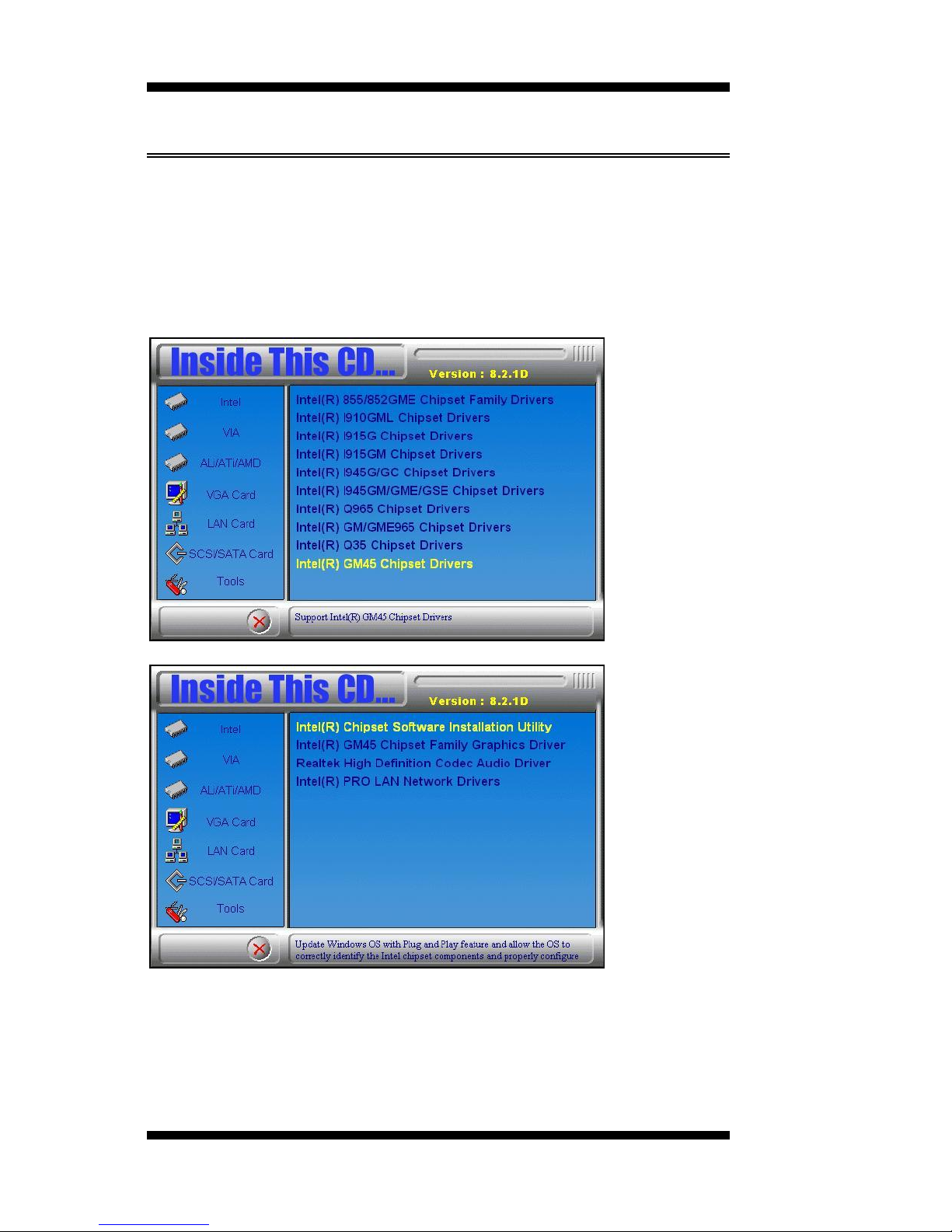
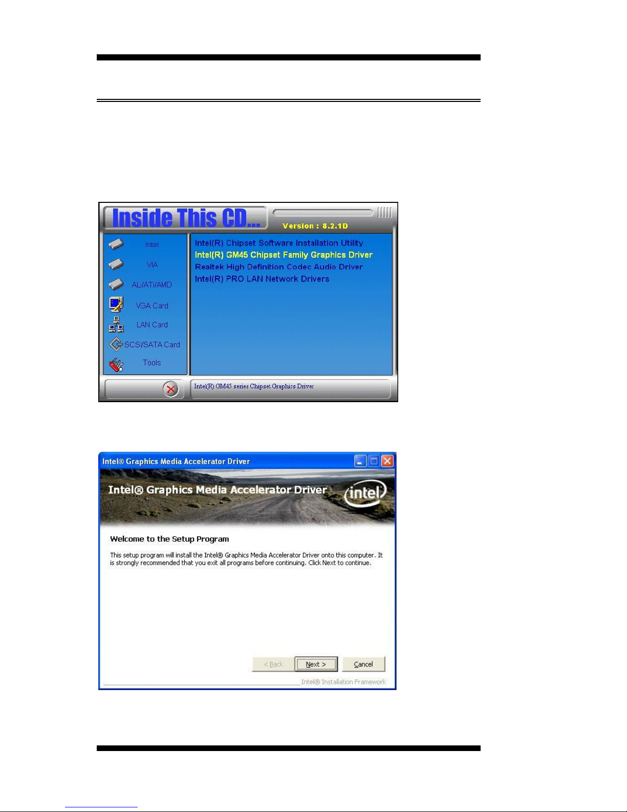
1. Insert the CD that comes with the board. Click Intel and then Intel(R)
GM45 Chipset Drivers.
2. Click Intel(R) Chipset Software Installation Utility.
3. When the Welcome screen to the Intel® Chipset Device Software
appears, click Next to continue.
Page 51

DRIVERS INSTALLATION
MI945AF User’s Manual 47
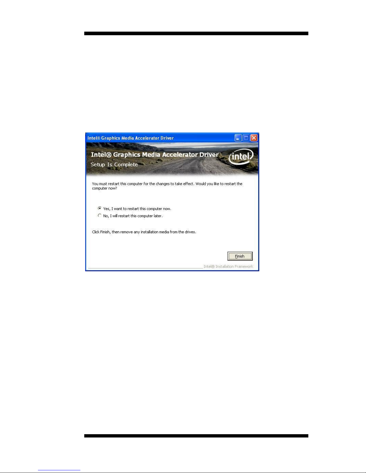
4. Click Yes to accept the software license agreement and proceed with
the installation process.
5. On the Readme File Information screen, click Next to continue the
installation.
6. The Setup process is now complete. Click Finish to restart the
computer and for changes to take effect.
Page 52
DRIVERS INSTALLATION
48
MI945AF User’s Manual
VGA Drivers Installation
To install the VGA drivers, follow the steps below to proceed with the
installation.
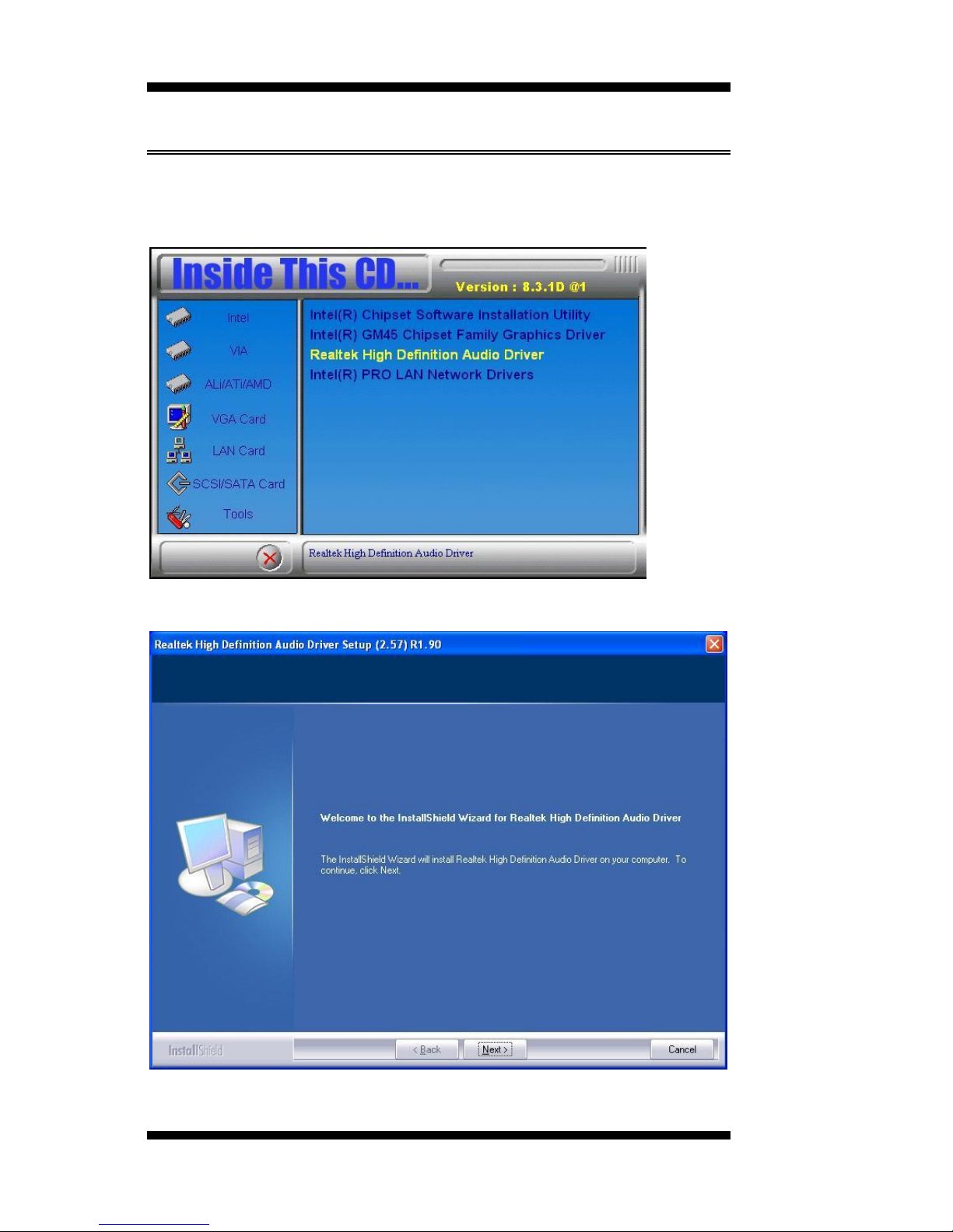
1. Insert the CD that comes with the board. Click Intel and then Intel(R)
GM45 Chipset Drivers.
2. Click Intel(R) GM45 Chipset Family Graphics Driver.
3. When the Welcome screen to the Setup Program appears, click Next to
continue.
Page 53
DRIVERS INSTALLATION
MI945AF User’s Manual 49
4. Click Yes to to agree with the license agreement and continue the
installation.
5. On the Readme File Information screen, click Next to continue the
installation of the Intel® Graphics Media Accelerator Driver.
6. On Setup Progress screen, click Next to continue.
7. Setup complete. Click Finish to restart the computer and for changes
to take effect.
Page 54
DRIVERS INSTALLATION
50
MI945AF User’s Manual
Realtek Audio Driver Installation
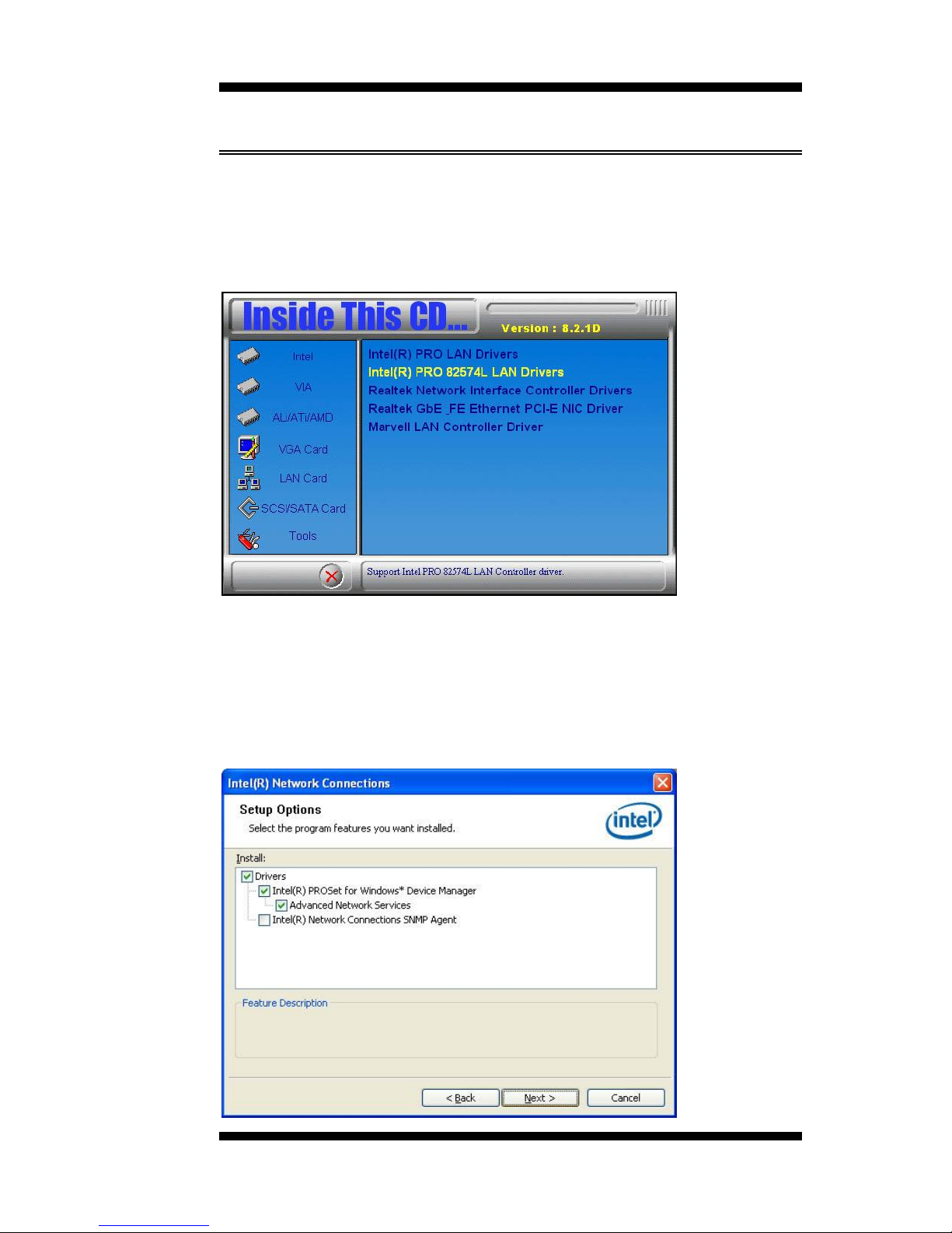
1. Insert the CD that comes with the board. Click Intel and then Intel(R)
GM45 Chipset Drivers.
2. Click Realtek High Definition Audio Driver.
3. On the Welcome to the InstallShield Wizard screen, click Next.
3. InstallShield Wizard is complete. Click Finish to restart the computer.
Page 55
DRIVERS INSTALLATION
MI945AF User’s Manual 51
LAN Drivers Installation
Follow the steps below to install the Intel LAN drivers. This one
installation will cover both 82574L and 82567LM LAN controllers.
1. Insert the CD that comes with the motherboard. Click LAN Card and
then Intel(R) PRO 82574L LAN Drivers.
2. When the Welcome screen to the InstallShield Wizard for Intel®
Network Connections appears, click Next. On the next screen, click Yes
to to agree with the license agreement.
3. Click the checkbox for Drivers in the Setup Options screen to select it
and click Next to continue.
Page 56
DRIVERS INSTALLATION
52
MI945AF User’s Manual
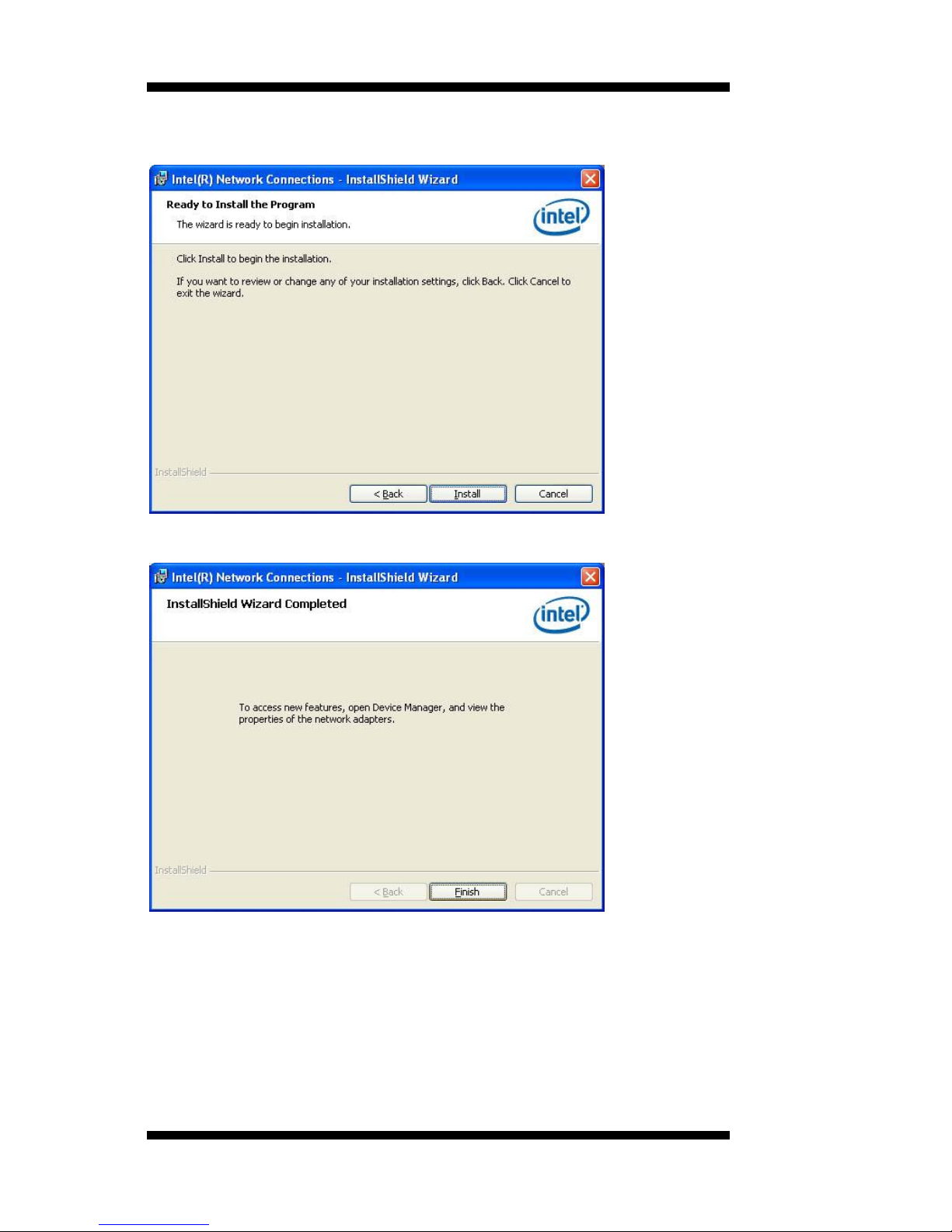
4. The wizard is ready to begin installation. Click Install to begin the
installation.
5. When InstallShield Wizard is complete, click Finish.
Remarks: This Intel® PRO 82574L LAN drivers support both Intel
82574L and 82567LM LAN controllers.
Page 57
DRIVERS INSTALLATION
MI945AF User’s Manual 53
Intel® Management Engine Interface
Follow the steps below to install the Intel Management Engine.
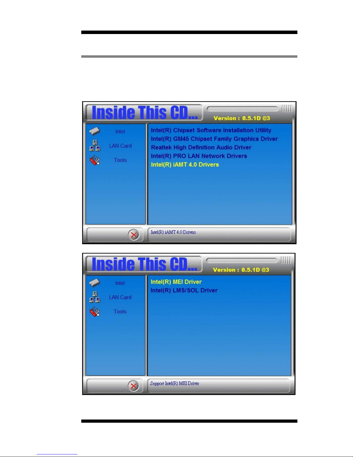
1. Insert the drivers disc that comes with the motherboard. Click Intel
and then Intel(R) AMT 4.0 Drivers, then Intel(R) MEI Driver.
Page 58
DRIVERS INSTALLATION
54
MI945AF User’s Manual
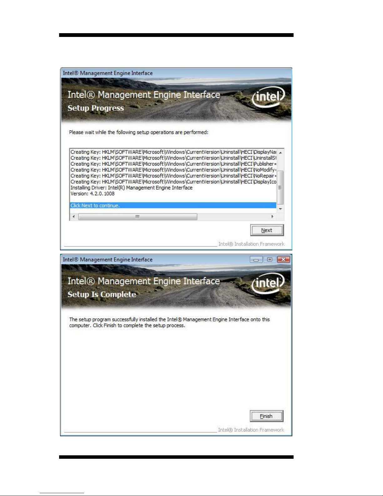
2. When the Setup Progress screen appears, click Next. Then, click
Finish when the setup progress has been successfully installed.
Page 59
DRIVERS INSTALLATION
MI945AF User’s Manual 55
Intel® AMT SOL Driver Installation
Follow the steps below to install the Intel Management Engine.
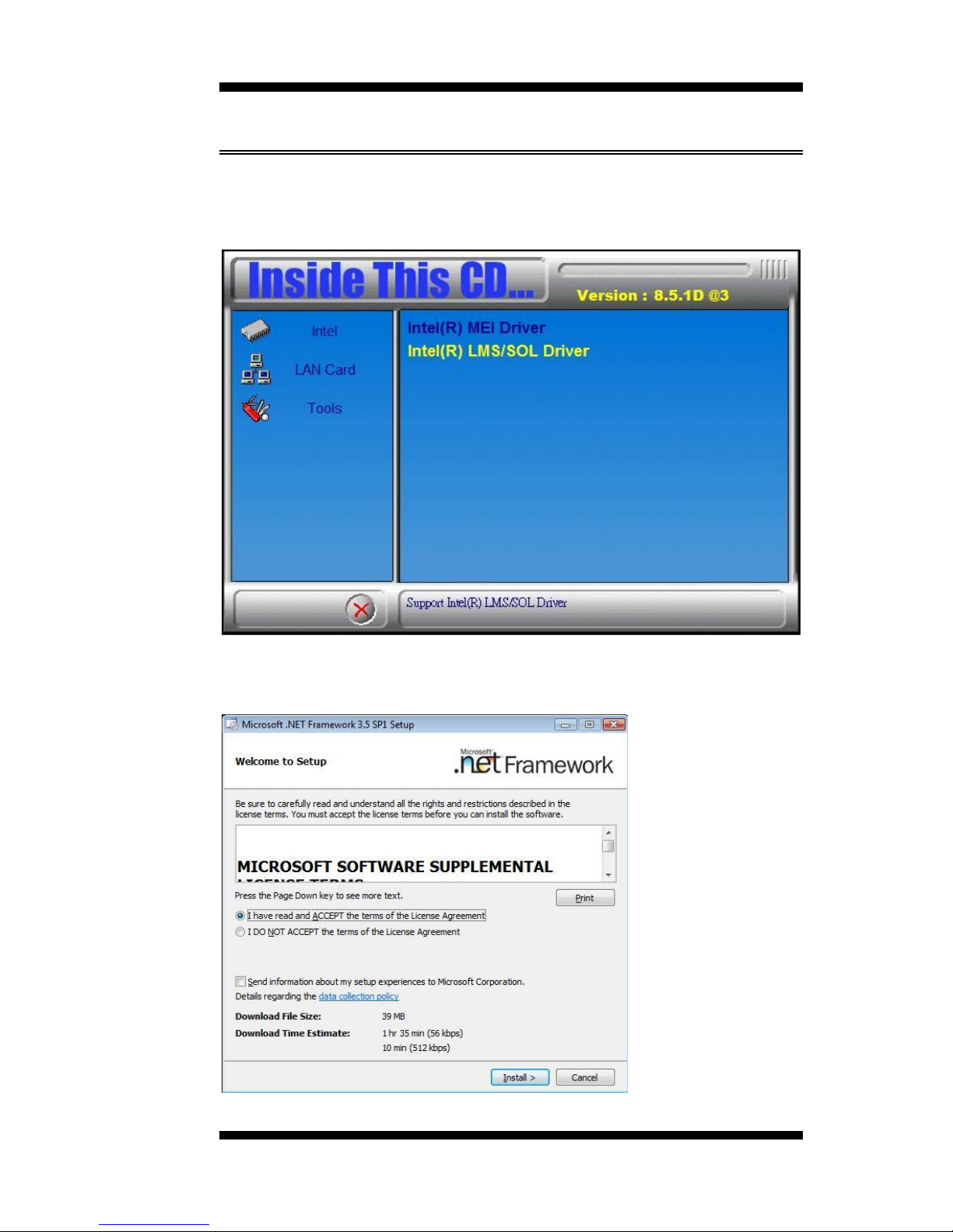
1. Insert the drivers disc that comes with the motherboard. Click Intel
and then Intel(R) AMT 4.0 Drivers, then Intel(R) LMS/SOL Driver.
2. On the Setup screen for Microsoft .NET Framework 3.5 SPI, click
Install. When Setup is complete, click Exit.
Page 60
DRIVERS INSTALLATION
56
MI945AF User’s Manual
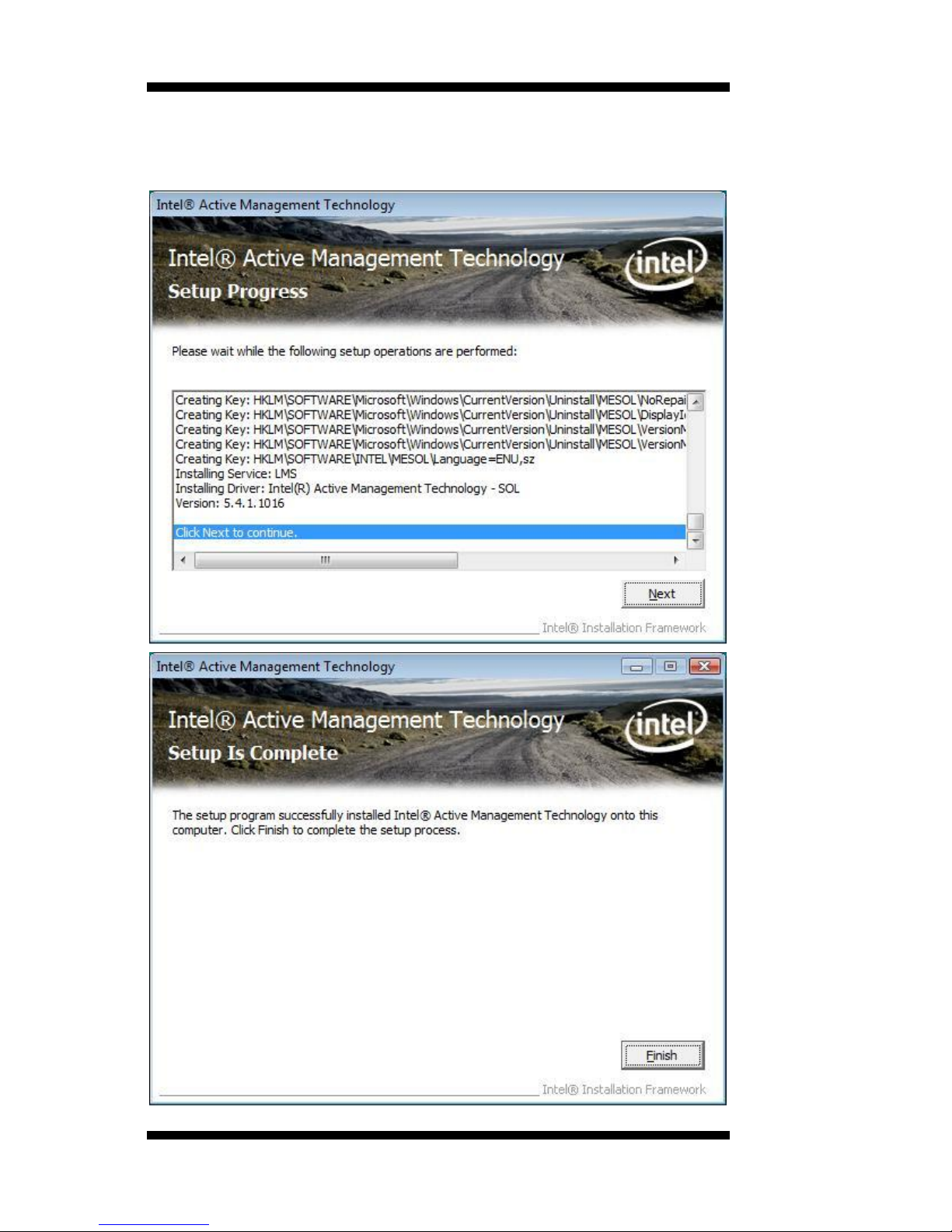
3. The next screen shows the Intel® Active Management Technology
setup progress where the Intel AMT SOL driver is being installed. Click
Next. Click Finish when setup process is complete.
Page 61

APPENDIX
MI945AF User’s Manual 57
Appendix
A. I/O Port Address Map
Each peripheral device in the system is assigned a set of I/O port
addresses which also becomes the identity of the device. The following
table lists the I/O port addresses used.
Address
Device Description
000h - 01Fh
DMA Controller #1
020h - 03Fh
Interrupt Controller #1
040h - 05Fh
Timer
060h - 06Fh
Keyboard Controller
070h - 07Fh
Real Time Clock, NMI
080h - 09Fh
DMA Page Register
0A0h - 0BFh
Interrupt Controller #2
0C0h - 0DFh
DMA Controller #2
0F0h
Clear Math Coprocessor Busy Signal
0F1h
Reset Math Coprocessor
1F0h - 1F7h
IDE Interface
278 - 27F
Parallel Port #2(LPT2)
2F8h - 2FFh
Serial Port #2(COM2)
2B0 - 2DF
Graphics adapter Controller
378h - 3FFh
Parallel Port #1(LPT1)
360 - 36F
Network Ports
3B0 - 3BF
Monochrome & Printer adapter
3C0 - 3CF
EGA adapter
3D0 - 3DF
CGA adapter
3F0h - 3F7h
Floppy Disk Controller
3F8h - 3FFh
Serial Port #1(COM1)
Page 62

APPENDIX
58
MI945AF User’s Manual
B. Interrupt Request Lines (IRQ)
Peripheral devices use interrupt request lines to notify CPU for the
service required. The following table shows the IRQ used by the devices
on board.
Level
Function
IRQ0
System Timer Output
IRQ1
Keyboard
IRQ2
Interrupt Cascade
IRQ3
Serial Port #2
IRQ4
Serial Port #1
IRQ5
Reserved
IRQ6
Floppy Disk Controller
IRQ7
Parallel Port #1
IRQ8
Real Time Clock
IRQ9
Reserved
IRQ10
Reserved
IRQ11
Reserved
IRQ12
PS/2 Mouse
IRQ13
80287
IRQ14
Primary IDE
IRQ15
Secondary IDE
Page 63

APPENDIX
MI945AF User’s Manual 59
C. Watchdog Timer Configuration
The WDT is used to generate a variety of output signals after a user
programmable count. The WDT is suitable for use in the prevention of
system lock-up, such as when software becomes trapped in a deadlock.
Under these sorts of circumstances, the timer will count to zero and the
selected outputs will be driven. Under normal circumstance, the user will
restart the WDT at regular intervals before the timer counts to zero.
SAMPLE CODE:
//===========================================================================
//
// THIS CODE AND INFORMATION IS PROVIDED "AS IS" WITHOUT WARRANTY OF ANY
// KIND, EITHER EXPRESSED OR IMPLIED, INCLUDING BUT NOT LIMITED TO THE
// IMPLIED WARRANTIES OF MERCHANTABILITY AND/OR FITNESS FOR A PARTICULAR
// PURPOSE.
//
//===========================================================================
#include <stdio.h>
#include <stdlib.h>
#include "W627DHG.H"
//===========================================================================
int main (int argc, char *argv[]);
void copyright(void);
void EnableWDT(int);
void DisableWDT(void);
//===========================================================================
int main (int argc, char *argv[])
{
unsigned char bBuf;
unsigned char bTime;
char **endptr;
copyright();
if (argc != 2)
{
printf(" Parameter incorrect!!\n");
return 1;
}
if (Init_W627DHG() == 0)
{
printf(" Winbond 83627HF is not detected, program abort.\n");
return 1;
}
bTime = strtol (argv[1], endptr, 10);
printf("System will reset after %d seconds\n", bTime);
EnableWDT(bTime);
return 0;
}
//===========================================================================
Page 64

APPENDIX
60
MI945AF User’s Manual
void copyright(void)
{
printf("\n======== Winbond 83627DHG Watch Timer Tester (AUTO DETECT) ========\n"\
" Usage : W627E_WD reset_time\n"\
" Ex : W627E_WD 3 => reset system after 3 second\n"\
" W627E_WD 0 => disable watch dog timer\n");
}
//===========================================================================
void EnableWDT(int interval)
{
unsigned char bBuf;
bBuf = Get_W627DHG_Reg( 0x2D);
bBuf &= (!0x01);
Set_W627DHG_Reg( 0x2D, bBuf);
//Enable WDTO
Set_W627DHG_LD( 0x08);
//switch to logic device 8
Set_W627DHG_Reg( 0x30, 0x01); //enable timer
bBuf = Get_W627DHG_Reg( 0xF5);
bBuf &= (!0x08);
Set_W627DHG_Reg( 0xF5, bBuf); //count mode
is second
Set_W627DHG_Reg( 0xF6, interval); //set timer
}
//===========================================================================
void DisableWDT(void)
{
Set_W627DHG_LD(0x08);
//switch to logic device 8
Set_W627DHG_Reg(0xF6, 0x00); //clear
watchdog timer
Set_W627DHG_Reg(0x30, 0x00); //watchdog
disabled
}
//===========================================================================
Page 65

APPENDIX
MI945AF User’s Manual 61
//===========================================================================
//
// THIS CODE AND INFORMATION IS PROVIDED "AS IS" WITHOUT WARRANTY OF ANY
// KIND, EITHER EXPRESSED OR IMPLIED, INCLUDING BUT NOT LIMITED TO THE
// IMPLIED WARRANTIES OF MERCHANTABILITY AND/OR FITNESS FOR A PARTICULAR
// PURPOSE.
//
//===========================================================================
#include "W627DHG.H"
#include <dos.h>
//===========================================================================
unsigned int W627DHG_BASE;
void Unlock_W627DHG (void);
void Lock_W627DHG (void);
//===========================================================================
unsigned int Init_W627DHG(void)
{
unsigned int result;
unsigned char ucDid;
W627DHG_BASE = 0x2E;
result = W627DHG_BASE;
ucDid = Get_W627DHG_Reg(0x20);
if (ucDid == 0x88)
{ goto Init_Finish; }
W627DHG_BASE = 0x4E;
result = W627DHG_BASE;
ucDid = Get_W627DHG_Reg(0x20);
if (ucDid == 0x88)
{ goto Init_Finish; }
W627DHG_BASE = 0x00;
result = W627DHG_BASE;
Init_Finish:
return (result);
}
//===========================================================================
void Unlock_W627DHG (void)
{
outportb(W627DHG_INDEX_PORT, W627DHG_UNLOCK);
outportb(W627DHG_INDEX_PORT, W627DHG_UNLOCK);
}
//===========================================================================
void Lock_W627DHG (void)
{
outportb(W627DHG_INDEX_PORT, W627DHG_LOCK);
}
//===========================================================================
void Set_W627DHG_LD( unsigned char LD)
{
Unlock_W627DHG();
outportb(W627DHG_INDEX_PORT, W627DHG_REG_LD);
outportb(W627DHG_DATA_PORT, LD);
Lock_W627DHG();
}
Page 66

APPENDIX
62
MI945AF User’s Manual
//===========================================================================
void Set_W627DHG_Reg( unsigned char REG, unsigned char DATA)
{
Unlock_W627DHG();
outportb(W627DHG_INDEX_PORT, REG);
outportb(W627DHG_DATA_PORT, DATA);
Lock_W627DHG();
}
//===========================================================================
unsigned char Get_W627DHG_Reg(unsigned char REG)
{
unsigned char Result;
Unlock_W627DHG();
outportb(W627DHG_INDEX_PORT, REG);
Result = inportb(W627DHG_DATA_PORT);
Lock_W627DHG();
return Result;
}
//===========================================================================
//===========================================================================
//
// THIS CODE AND INFORMATION IS PROVIDED "AS IS" WITHOUT WARRANTY OF ANY
// KIND, EITHER EXPRESSED OR IMPLIED, INCLUDING BUT NOT LIMITED TO THE
// IMPLIED WARRANTIES OF MERCHANTABILITY AND/OR FITNESS FOR A PARTICULAR
// PURPOSE.
//
//===========================================================================
#ifndef __W627DHG_H
#define __W627DHG_H 1
//===========================================================================
#define W627DHG_INDEX_PORT (W627DHG_BASE)
#define W627DHG_DATA_PORT (W627DHG_BASE+1)
//===========================================================================
#define W627DHG_REG_LD 0x07
//===========================================================================
#define W627DHG_UNLOCK 0x87
#define W627DHG_LOCK 0xAA
//===========================================================================
unsigned int Init_W627DHG(void);
void Set_W627DHG_LD( unsigned char);
void Set_W627DHG_Reg( unsigned char, unsigned char);
unsigned char Get_W627DHG_Reg( unsigned char);
//===========================================================================
#endif //__W627DHG_H
 Loading...