

Page 1
AWA
W6900S/SF
29”(74 CM) COLOUR TV WITH
INFRARED REMOTE CONTROL
SERVICE MANUAL
Page 2
SAFETY INSTRUCTIONS
WARNING: BEFORE SERVICING THIS CHASSIS, READ THE "X-RAY
RADIATION PRECAUTION", "SAFETY PRECAUTION" AND "PRODUCT SAFETY
NOTICE" DESCRIBED BELOW.
X-RAY RADIATION PRECAUTION
1. Extremely high voltage of the picture tube may result in producing potentially hazardous X-RAY RADIATION.
To avoid such hazards, the high voltage must not be above the specified limit.
The nominal value of the high voltage of this receiver is about 30.4 kV at zero beam current (minimum
brightness) under 175-245V AC power source.
The high voltage must, under any circumstances, not exceed about 36kV.
Each time this receiver requires servicing, the high voltage should be checked according to the HIGH
VOLTAGE CHECK procedure at the back of this manual. it is recommended to record the reading of the high
voltage in the service record each time. Using an accurate and reliable high impedance and high voltage meter
is quite important.
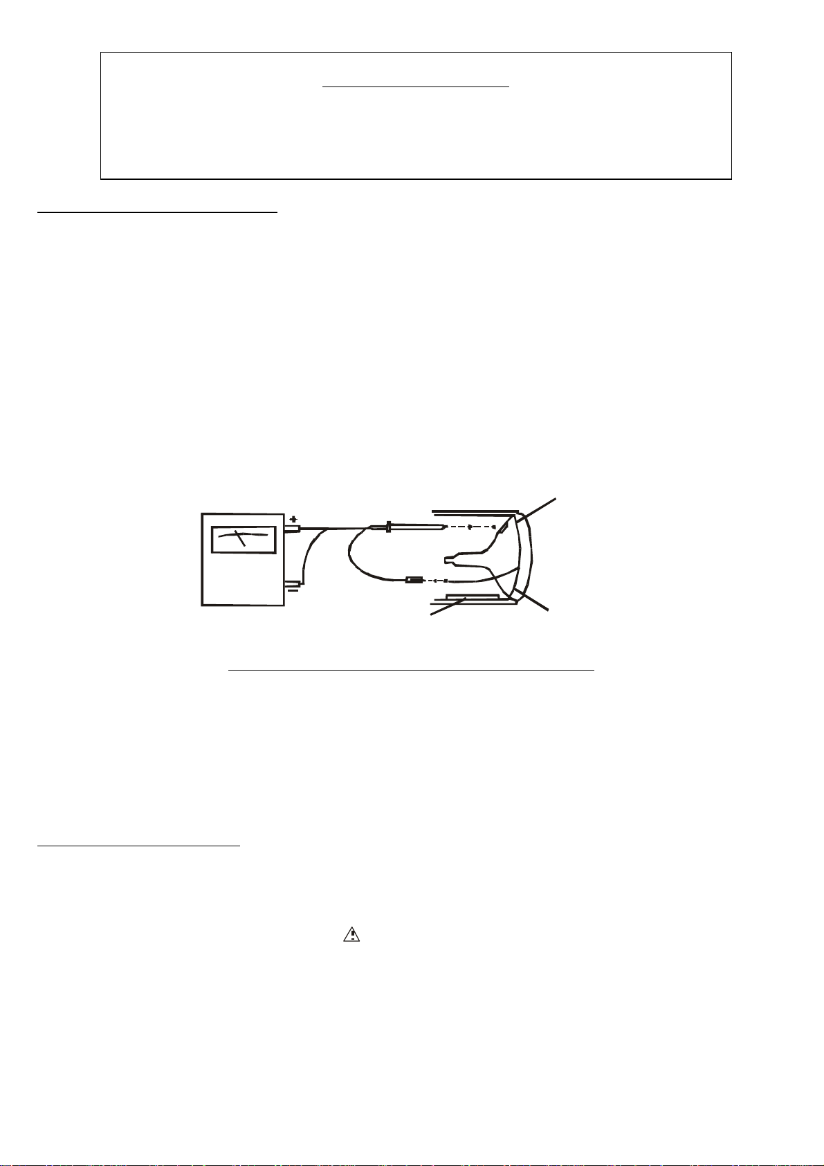
Connect the NEGATIVE and POSITIVE probe of a high voltage meter to the "ground" and the high voltage
anode cap of the picture tube respectively.
Picture tube high voltage anode cap
High impedance and high voltagh meter Chassis
Picture tube ground
HIGH VOLTAGE CHECK CONNECTION DIAGRAM
2. The only source of X-RAY RADIATION in this receiver is the picture tube. For ensuring the intensity of
X-RAY RADIATION from the picture tube being within the specified safety limit, the replacement picture tube
must be exactly the same type specified in the parts list.
3. Some parts in this receiver have special safety-related characteristics which would affect X-RAY
RADIATION protection. For safety, parts replacement should be carried out only after referring to the
"PRODUCT SAFETY NOTICE" below.
PRODUCT SAFETY NOTICE
Many electrical and mechanical parts in this receiver have special safety-related characteristics (directly relate to
high voltage, high temperature or electric shock) which are not easily seen by visual inspection. Whenever
replacing such components, make sure that the replacement parts can provide effective X-RAY RADIATION
protection even though their high voltage and wattage can meet the specification of the original design. Such parts
can be identified by shading and marking with in the schematic diagram and the parts list.
Before replacing any of these components, read the parts list in this manual carefully. Using substitute parts which
do not have the same safety characteristics as the ones specified in the parts list may create excessive X-RAY
RADIATION.
2
Page 3
I2C BUS CONCEPT
(1). Characteristics
1.1 I2C Bus consists of clock (SCL) and data (SDA) lines.
1.2 It transmits data among integrated circuits in full duplex mode.
1.3 It is composed of a main IC chip (CPU) and one or more sub-IC chips.
l The CPU mainly operates data transmissions and also generates clock signal.
l The CPU also controls all sub-IC chips, making them work.
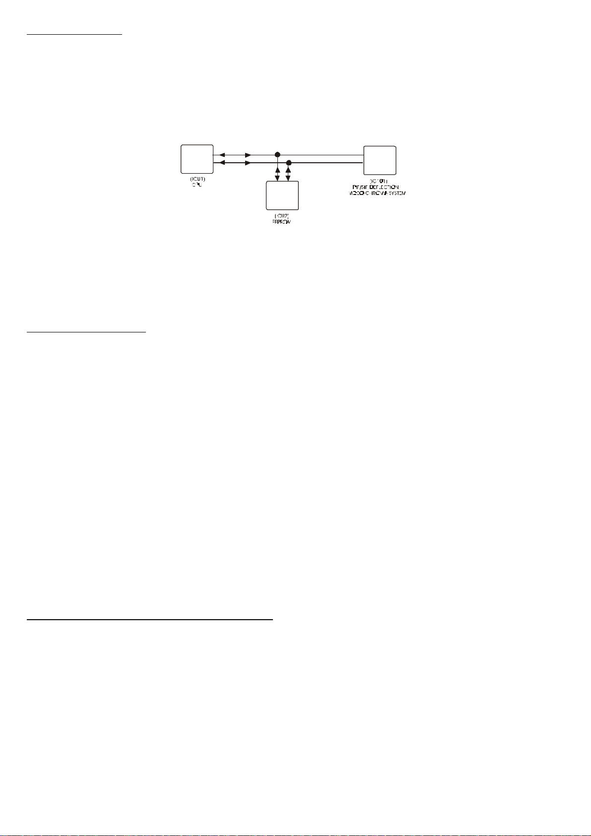
(2). I2C Bus Application in this TV unit
SDA
SCL
SDA
SCL
SDA
SCL
In this TV unit, ICU1 is the main chip while ICU2, IC101 and other chips are regarded as sub-chips.
2.1 ICU1 (CPU) controls the functions of IC101 via the I2C bus between them.
2.2 The data of channel positions, BT voltage, band, AFT, clear, volume, power on/off, timer, color, etc. are
written into, stored in and read out from ICU2 via the I2C bus.
SAFETY PRECAUTION
1. High voltage of 27-32kV is always present inside this receiver when it is operating, so be cautious of electric
shock hazard while removing the back cabinet to process adjustment.
(A) Servicing should not be attempted by any person who is not very familiar with the required re-cautions
when working on this high-voltage equipment.
(B) Before removing the anode cap of the picture tube, discharge the high voltage potential from the picture tube
anode several times by short-circuiting the anode together with its ground to keep off electric shock hazard.
(C) Perfectly discharge the high voltage potential of the picture tube before handling the picture tube which is
highly evacuated. When it is broken, danger may be caused because of the violent burst of its glass
fragments.
2. If the fuse in this receiver is blown, replace it with the type specified in the chassis parts list or with the same
specifications (never use other types).
3. Whenever replacing with new components, twist the lead wires of the component together with the concerned
residual leads before soldering.
4. Whenever replacing with a new high wattage resistor (such as oxide metal film resistor) on any of the circuit
boards, keep the body of the resistor 10 mm above the circuit board.
5. Keep all connecting wires away from the components of high voltage or high temperature.
6. This receiver is designed to operate at AC 175-245V~50/60Hz, NEVER connect to DC supply or any other
power sources.
7. The main chassis of this receiver is perfectly isolated.
INSTALLATION AND SERVICE ADJUSTMENTS
GENERAL INFORMATION:
Normally, this receiver have been thoroughly checked and adjusted before leaving the factory; therefore it should
operate normally and produce perfect color and B/W pictures upon installation. However, several minor
adjustments may be required according to the practical situation.
This receiver is packed in a cardboard carton during transportation. Carefully draw it out from the carton and
remove all packing materials.
Plug the receiver's power cord into a convenient 175-245V 50/60Hz AC two pin power outlet.
Check and adjust all the customer controls such as BRIGHTNESS, CONTRAST and COLOUR to obtain natural
color or B/W picture.
3
Page 4
AUTOMATIC DEGAUSSING :
Input Terminals (Video),
A degaussing coil is mounted around the picture tube so that external degaussing after moving the receiver is
normally unnecessary, providing the receiver is properly degaussed upon installation. The degaussing coil
operates for about 1 second after the power to the receiver is switched ON. If the set is moved or faced in a
different direction, the power switch must be switched off at least one hour in order that the automatic degaussing
circuit operates properly. And then the receiver turned it again.
Should the chassis or parts of the cabinet become magnetized to cause poor colour purity, use an external
degaussing coil. Slowly move the degaussing coil around the faceplate of the picture tube, the sides and front of
the receiver and slowly withdraw the coil to a distance of about 2 meters before disconnecting it from AC source.
If colour shading still persists, perform the “COLOUR PURITY ADJUSTMENT” and “CONVERGENCE
ADJUSTMENTS” procedures as mentioned later.
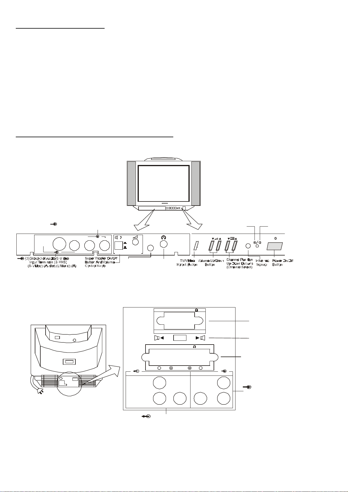
LOCATION OF CONTROLS AND SWITCHES
Front View (Front Configuration)
(2)Groups 2 of Audio/Video Input
Terminals (Video), (Audio), (L/Mono),
S-VIDEO
AUDIO
R
3
AUDIO
2
VIDEOL/MONO
:
SUPER WOOFER
MENU
Button
Rear View (Back Configuration)
ON
OFF
Headphone Jack
(3.5mm Dia, 16ohm)
MENU
SUPER WOOFER 8
EXT. SPEAKER 8
+
R
AUDIO(MONITOR) AUDIOVIDEOVIDEO
R
INT.
EXT.
MENU
L
Standby
(Red)
Super Woofer Out Terminals
Main Speakers Output Terminals
+
L/MONOL/MONO
R
Power
(Green)
Speaker Switch (EXT/INT)
(1)Group of Audio/Video
(Audio), (L/Mono),(R)
(Monition) Tv Out Terminals
(Video), (Audio), (L/Mono),(R)
4
Page 5
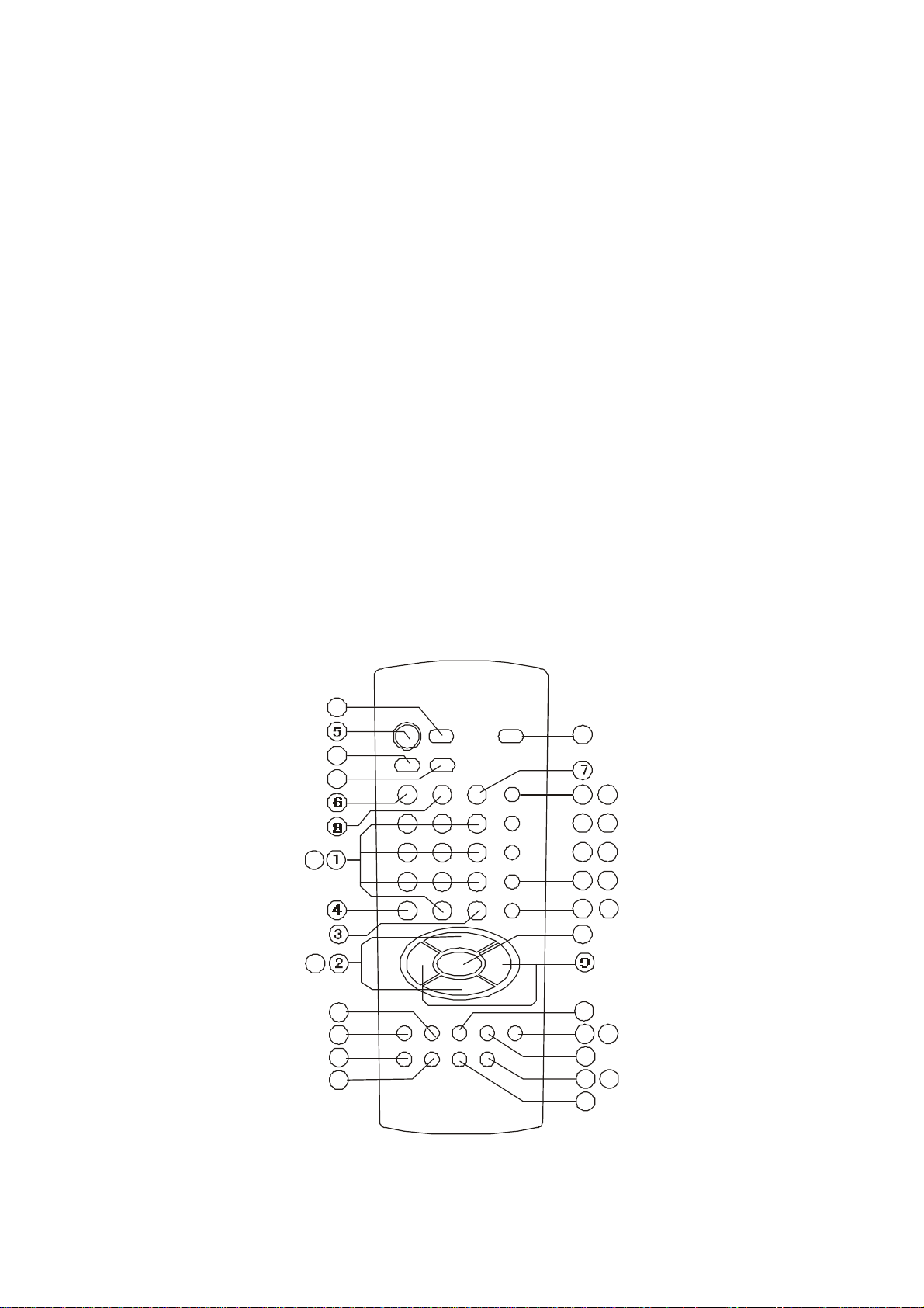
Remote Control Unit
There are 38 buttons on the remote control. It operates with infra-red beam which is not affected by noise or other
interferences. Make sure strong light never strikes on the infra-red receiver; otherwise, it would obstruct the
remote control working normally with the TV unit.
Do not drop or expose it to high temperature.
*16-17 (FOR GERMAN STEREO ONLY)
*19-36 (FOR TELETEXT ONLY)
1. NUMBER (0-9) BUTTONS
2. PROGRAM (UP/DOWN) BUTTONS
3. AV BUTTON
4. TV BUTTON
5. STANDBY BUTTON
6. PERSONAL PREFERENCE BUTTON (PP)
7. SOUND MUTING BUTTON
8. STATUS BUTTON
9. VOLUME (UP/DOWN) BUTTONS
10. MENU BUTTON
11. RED (PICTURE MENU) BUTTON
12. GREEN (SOUND MENU) BUTTON
13. YELLOW (OTHER MENU) BUTTON
14. CYAN (INSTALL MENU) BUTTON
15. WHITE (TIME MENU) BUTTON
16. STEREO/MONO & DUAL I/II BUTTON
17. EFFECT BUTTON
18. SWAP BUTTON
19. SUBTITLE BUTTON
20. TXT. BUTTON
21. MIX. BUTTON
22. CANCEL BUTTON
23. HOLD BUTTONSIZE BUTTON
24. SIZE BUTTON
25. REVEAL BUTTON
26. TIME BUTTON
27. SUBCODE BUTTON
28. DIGIT ENTRY (0-9) BUTTONS
29. PAGE NUMBER UP / DOWN BUTTONS
30. PREVIOUS BUTTON
31. TOP/FLOP/SIMPLE BUTTON
32-35. COLOR BUTTONS
36. WHITE (INDEX) BUTTON
37. SERVICE BUTTON
28
29
37
16
17
21
20
24
23
19
11
12
13
14
15
10
22
18 31
30
26 27
25
32
33
34
35
36
5
Page 6
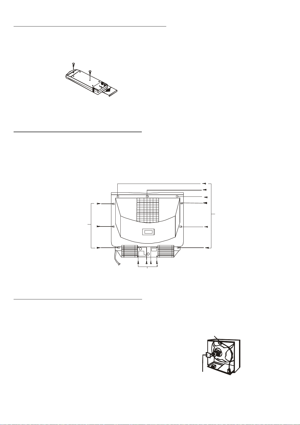
HOW TO DISASSEMBLE REMOTE CONTROL HAND UNIT (see Fig. 1)
1. Remove the battery cover and loosen the screws.
2. Open one side of the back cabinet to take it away from the front cabinet.
Fig. 1
METHOD OF REMOVING BACK CABINET (see Fig. 2)
Attn.: Before disassembling the back cabinet, first draw the power cord plug of the receiver from AC outlet.
1. Disconnect the antenna cable from the antenna terminal.
2. Loosen the 5 pieces of screw (A) used in fixing the antenna jack plate on the back cabinet.
3. Loosen the 9 pieces of screw (B) used in fixing the back cabinet to the front cabinet; then remove the back
cabinet.
Screws(B)
Screws(A)
Fig.2
METHOD OF REMOVING MAIN CHASSIS (see Fig. 3 & 4)
After removing the back cabinet, proceed the following procedures accordingly.
1. To avoid electric shock hazard, discharge the high Fig.3
voltage potential from the picture tube anode
several times by short-circuiting the positive anode
of the picture tube with its ground before detaching
the high-voltage anode cap.
2. Unsolder and detach the ground wire of the picture
tube from the picture tube socket board.
3. Detach the picture tube socket board.
4. Detach the high-voltage anode cap.
5. Unplug Socket F, U, V, A, B, K or X and P.
6. Take out the chassis from the chassis holder.
High-volotage anode cap
Picture tube socket board
Screws(B)
6
Page 7
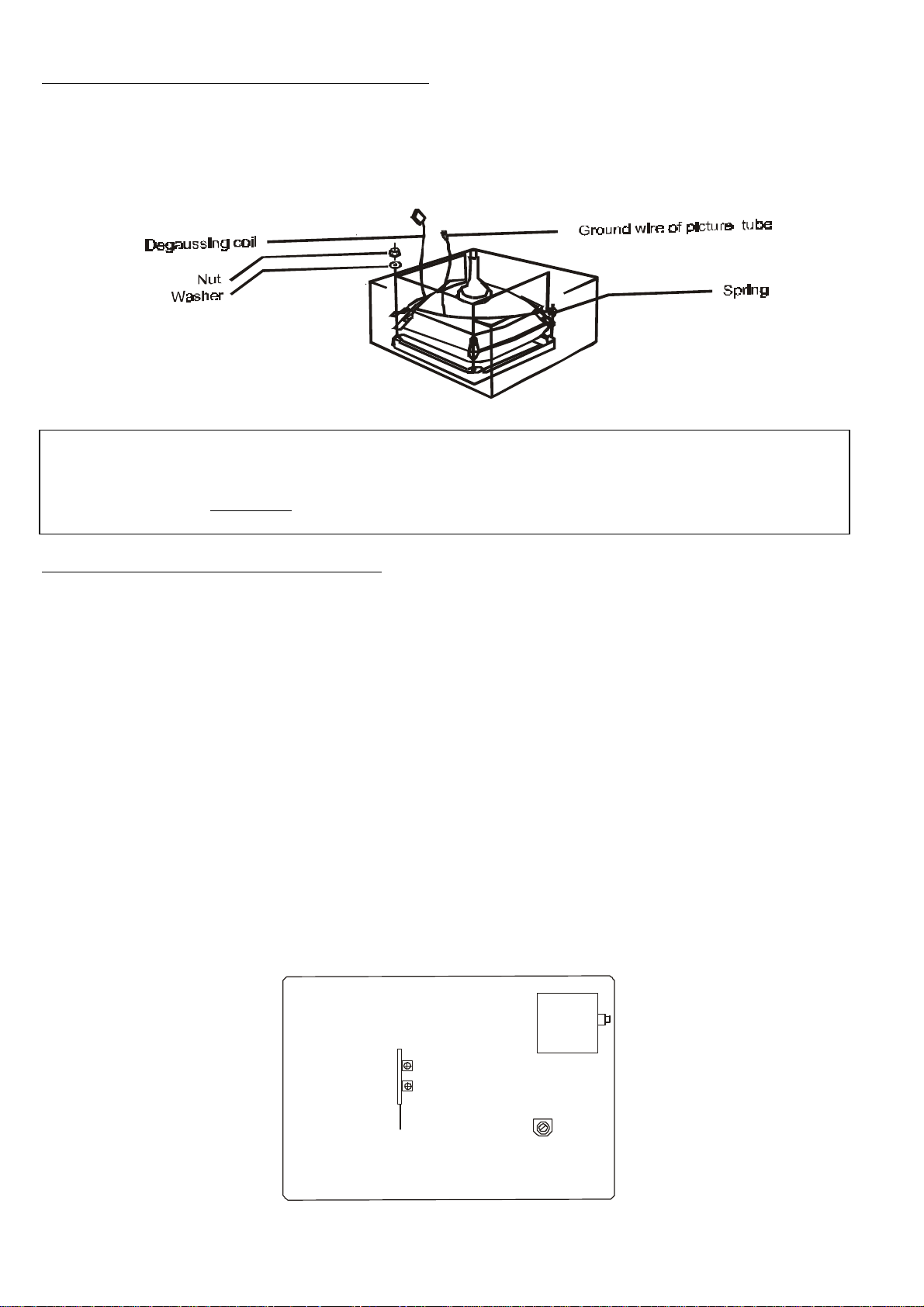
METHOD OF REMOVING PICTURE TUBE (see Fig. 4)
MAIN CHASSIS PC BOARD
After taking out the chassis holder (main chassis), proceed the following procedures accordingly:
1. Turn the receiver down and let the screen of the picture tube face downward, and put it on a soft cushion.
2. Loosen the 4 pieces of nut used in fixing the picture tube on the front cabinet, remove the degaussing coil; then
use two hands to hold the edges of the picture tube tightly and draw it out.
3. Detach the ground wire of the picture tube which is attached to the lugs of the picture tube with springs.
Fig.4
SUGGESTION: Before servicing the chassis, please read through “X-RAY RADIATION
PRECAUTION", "SAFETY PRECAUTION" and "PRODUCT SAFETY NOTICE" at
Page 2 & 3 of this manual.
GENERAL ADJUSTMENT INSTRUCTIONS
This receiver is transistorized and special care should be taken when servicing. If not necessary, do not attempt
any adjustments because the requirements of the procedures are very stringent. Read the following matters before
attempting any adjustments.
An isolation transformer should be used during any dynamic service to avoid possible electric shock hazard.
The test equipment specified or their equivalent is required in having proper alignment. Using unsuitable
equipment, which do not meet these requirements, may result in improper alignment.
Correct matching of the equipment is essential. Failure of using proper matching will result in responses which
cannot show the true operation of the receiver.
Excessive signal by using a sweep generator can cause the receiver circuit overloaded. Overloading should be
avoided to obtain a true response curve. Insertion of markers by using the marker generator should not cause the
response curve distorted.
The AC power line voltage should be accurately kept during alignment.
During the process of alignment, the AC voltage should be kept in the range from 215V to 225V (50Hz).
Do not attempt to connect or disconnect any wire while the receiver is in operation. Make sure the power cord is
unplugged before replacing any parts in the receiver.
Unless specified, start adjustments after the receiver is turned on for at least 30 seconds.
CHASSIS'S TOP VIEW
VRC2
VRC1
E-W CORRECTION PC BOARD
7
T902
VR 501
Page 8

NOTICE:
1. Resistor
All resistors are of 1/8W Carbon Film type except those listed below. The unit of measure for resistor is OHM
(K = 1,000 ohm, M = 1,000,000 ohm).
CARBON FILM RESISTOR
CARBON COMPOSITION RESISTOR
METAL OXIDE RESISTOR +5%
METAL OXIDE RESISTOR +2%
FUSIBLE RESISTOR
NON-INFLAMMABLE RESISTOR
PTC THERMISTOR
VARIABLE RESISTOR
2. Capacitor
All capacitors are of 50V Ceramic type except those listed below. The unit of measure for capacitor is
FARAD (F) (UF = 0.000001 F, PF = UUF = 0.000001 UF)
CERAMIC CAPACITOR
TANTALUM CAPACITOR
POLYESTER FILM CAPACITOR
POLYPROPYLENE FILM CAPACITOR
ELECTROLYTIC CAPACITOR
TRIMMER CAPACITOR
METAL POLYESTER FILM CAPACITOR
3. Unit of Measure: UH
4. Test Point
5. Marking of Ground Wire
: Ground wire of chassis (COLD)
: Ground wire of external wire (HOT)
6. Voltage Measurement
The voltages at all points should be measured with a digital multi-meter, and the measuring conditions are as
follows:
Power Source: AC220V 50Hz
Receiving Signal: Color Bar Signal
All Control Buttons: in Normal Position
7. Waveform
The numeral in the small circle represents the number of waveform, refer to the waveform table.
8. It is easy to locate a connection point in the direction as indicated by arrow (↗).
9. The schematic diagram in this manual is drawn according to the original design. It may be slightly different from
the actual circuit of the receiver because of any change in the circuit subject to no prior notice.
Notice: This circuit has a transformer to isolate the power supply circuit from the majority of the other
circuit, and they can be identified in the schematic diagram by marking with "HOT" and "COLD”.
Please note the followings .All circuits are "COLD" except power supply circuit.
(1) To avoid electric shock hazard, never touch the "HOT" and "COLD" circuit simultaneously.
(2) Never short-circuit the "HOT" and "COLD" circuit to prevent the fuse or other components from burning.
(3) Never connect any measuring equipment such as oscilloscope to both the "HOT" and "COLD" circuit at the
same time to prevent the fuse from burning. Also, connect the ground of the measuring equipment to the ground
of the circuit being tested.
(4) Never fail to unplug the power cord of the receiver before taking out the chassis.
8
Page 9

TEST EQUIPMENT :
EQUIPMENT SPECIFICATION
High Impedance Voltmeter Having an impedance of at least 100 Kohm.
Oscilloscope Volt sensitivity over 10mV input impedance over 1
Sweep/Marker Generator Output adjustable to at least 0.1 volts rms.
Colour Bar Generator With functions: BAR/DOT/SQUARE/SYSTEM
Power Supply
AC/DC Voltmeter High sensitive (better use digital voltmeter)
Isolation Transformer
Probe Low-capacitance / High impedance.
Mohm, below 10PF.
SELECT/VIDEO OUTPUT TERMINAL/CROSS-
HATCH/S-VIDEO OUTPUT TERMINAL functions and
green or red purity signal.
Source such as a battery or a well regulated and isolated
DC bias supply. (Adjust 0-20V)
Voltage adjustable type having capacity of more than
200 watts.
FM/AM Signal Generator National ; MODEL : VP8177A
B+ VOLTAGE ADJUSTMENT
Notice: (A) B+ voltage closely relates to the picture tube's positive high voltage.
(B) To prevent it from producing excessive hazardous X- RAY RADIATION, ensure that B+ voltage must
be adjusted to at the 125V (CE-6401/6418/6409/7405)/ 124V(or)140V (CE-7406)/ 145V (CE-8608)/
115V (CE-8616) POSITIONS.
1. Check the AC line voltage supplied is AC220V +-5% 50 Hz.
2. Turn in an active channel, adjust BRIGHTNESS and CONTRAST controls to obtain a normal picture.
3. Connect test point (C523) on the MAIN CHASSIS PCB with high impedance DC voltmeter.
4. Adjust VR501 (on the MAIN PCB) for B+ 125V +/-0.3V (CE-6401/6418/6409/7405)/ 124V(or)140V +/-
0.3V(CE-7406)/ 145V +/-0.3V(CE-8608)/ 115V +/-0.3V(CE-8616) voltage reading.
HIGH VOLTAGE CHECK:
CAUTION : There is no HIGH VOLTAGE ADJUSTMENT on this chassis.
a. Connect an accurate high voltage meter to the second anode of the picture tube.
b. Turn on the receiver and set the BRIGHTNESS, COLOUR and CONTRAST Controls to the minimum
(zero beam current).
c. High voltage will be measured below 35KV.
d. Adjust the BRIGHTNESS Control to both extremes to ensure the high voltage does not
exceed the limit of 34Kv under any circumstances.
FS CIRCUIT CHECK:
a. Push the Power Switch on and adjust all controls for normal operation.
b. Temporarily connect a 18Kohm resistor across R908 on the Main Chassis PC Board. Raster and sound
will disappear.
c. The receiver must remain in this state even after removing the resistor. This is the evidence that the
Fail Safe circuit is functioning properly.
d. To obtain a picture again, temporarily push the power switch off and allow the Fail Safe circuit move
than 30 seconds to reset. Then push the power switch on to produce a normal.
9
Page 10

FOCUS ALIGNMENT :
Tune in an active channel or Phillips Pattern. Adjust the Focus control on the FLYBACK
TRANSFORMER (T902) for well defined scanning lines in the center area on the screen.
SCREEN VOLTAGE (VG2) ADJUSTMENT
Apply a FULL BLACK signal with a colour bar signal generator.
Connect oscilloscope to measure pin of R132, R133 or R134 (Vbcmp) on the main board. Vbcmp means
DC-level of the black current measurement pulse.
Turn the CONTRAST and BRIGHTNESS controls to normal positions.
Turn the SCREEN VR anti-clockwise to get the minimum value.
Then turn the SCREEN VR clockwise slowly to get the reading of the DC-level at the RGB-output is 3.3V.
ATTN.: CE-7407 of SCREEN VOLTAGE adjustment reading of the DC-level at the RGB-output is 3.3V or
Screen Voltage is about DC 400V.
HORIZONTAL POSITION ADJUSTMENT
a. Receive the Phillips Pattern. Apply a crosshatch signal.
b. Set the contrast and colour to their minimum, and the brightness to its maximum.
c. Adjust (H-SHIFT) to move the picture at the center.
ATTN.: These settings should be done with separate test signals with a 50 Hz and a 60 Hz field frequency. These
parameters are stored in separate groups for 50 Hz and 60 Hz and are recalled or set, depending on the
field frequency of the currently received program.
VERTICAL ADJUSTMENT
Apply a crosshatch signal.
Adjust (V-SLOPE) to obtain half picture.
Adjust (V-S.CORR) to obtain a linear picture.
Adjust (V-SHIFT) to move the picture at the center.
Adjust (V-AMPL) to obtain rightful high picture.
ATTN.: These settings should be done with separate test signals with a 50 Hz and a 60 Hz field frequency. These
parameters are stored in separate groups for 50 Hz and 60 Hz and are recalled or set, depending on the
field frequency of the currently received program.
PICTURE WIDTH AND PINCUSHION DISTORTION ADJUSTMENT :
a. Perform this adjustment after the B+ volts and the Hor. CENTER adjustment are completed.
b. Receive a Phillips Pattern.
c. Set the contrast and colour to the minimum, and the brightness to the maximum.
d. Adjust the H. WIDTH Control (VRC2) for the horizontal width so that the white flags on the left and
right of the pattern just hide.
e. Adjust the DPC Control (VRC1) to correct the vertical line on left and right straight.
f. Readjust the WIDTH Control (VRC2) for the precision.
DELAY AGC ADJUSTMENT :
Apply a 60dbu level with standard colour bar signal to the antenna input.
Connect the probes of the high impedance DC voltmeter to C156.
Adjust (AGC-ADJ) to get the reading of 4 - 5V till obtaining a clear picture.
10
Page 11

CRT GREY SCALE ADJUSTMENT (WHITE BALANCE ADJUSTMENT):
Apply a white balance alignment signal with the white balance checker.
Adjust brightness and contrast suitable for the adjustment.
Adjust (R-GAIN), (G-GAIN) and (B-GAIN) to obtain a 9300 K colour temperature.
SAFETY PRECAUTION :
Dielectric voltage withstand test :
The following accessible parts should be stressed for a period of one second on each complete appliance
before it leaves the factory.
The test potential voltage not less than 3500V, 50Hz should be applied for 1 second between both blades of
the attachment plug cap. and the following parts :
Name of part Locations
1. Antenna Terminal Back Cabinet
2. AV input Terminals Front / Back Cabinet
3. AV output Terminals Back Cabinet
3. Enclosure Screws Back Cabinet
4. S-Video Sockets Front Cabinet
5. Ext. Speaker Terminals Back Cabinet
SOUND IF ALIGNMENT (BG-38.9MHz)
a. Apply IF signal (38.9 MHz, 10mV) to Pin 1 of D socket.
b. Set a signal generator to colour bar and dual transmission with internal modulation of 3 KHz on channel
1 and 1 KHz on channel 2.
c. Connect oscilloscope to pin 15 of ICF1 (TDA3857).
d. Align the 38.9MHz coil (LF4) for minimum picture contents.
STEREO SOUND AND DUAL SIF ALIGNMENT (BG - 5.5MHZ, DK - 6.5 MHz)
a. Set transmitter to dual sound mode and off the main sound modulation.
b. Adjust (LF5) 5.74MHz tank coil to minimum THD.
c. Set transmitter to BG mono sound mode, connect the dual vertical input of the oscilloscope to RF17
(MAIN SOUND) 5.5MHz and RF15 (SUB SOUND) 5.74MHz.
d. Adjust (LF6) 5.5MHz tank coil to minimum THD.
e. Change the sound to D/K system, adjust (LF7) 6.5MHz tank coil to minimum THD.
f. Re-align LF6 and LF7 to minimum THD both.
GERMAN STEREO FILTER COIL (LF8)
a. Set a signal generator to colour bar, stereo sound mode and off the main sound modulation (5.5 MHz
signal).
b. Connect the oscilloscope to Pin 5 of ICF2.
c. Adjust FILTER COIL (LF8) for the maximum reading on the oscilloscope (envelope waveform) with
the minimum distortion.
11
Page 12

COLOUR PURITY ADJUSTMENT
Note: Before attempting any color purity adjustments, the receiver should be turned on for at least 30
minutes. (see Figure 8). A few rubber wedges should be available for use whenever necessary
during the process of color purity adjustment.
a. Demagnetize the picture tube and cabinet using an external degaussing coil.
b. Turn the CONTRAST and BRIGHTNESS controls to maximum.
c. Adjust RED and BULE bias controls (R-GAIN) and (B-GAIN) to provide only a green raster.
Advance the GREEN bias control (G-GAIN) is necessary.
d. Loosen the clamp screw holding the yoke and slide the yoke and slide the yoke backward to provide
vertical green belt (zone) in the picture screen.
e. Remove the rubber wedges.
f. Rotate and spread the tabs of the purity magnet (See Fig. 9 around the neck of the picture tube until
the green belt is in the center of the screen. At the same time center the raster vertically.
g. Move the yoke slowly forward or backward until a uniform green screen is obtained. Tighten the
clamp screw of the yoke temporarily.
h. Check the purity of the red and blue raster by adjusting the bias controls.
i. Obtain a white raster, referring to "CRT GREY SCALE ADJUSTMENT (White Balance
Adjustment).
j. Proceed with convergence adjustment.
CENTER CONVERGENCE ADJUSTMENT :
Note : Before attempting any convergence adjustments, the receiver should have operated for at least fifteen
minutes.
a. Receive crosshatch pattern with a colour bar signal generator.
b. Adjust the BRIGHTNESS and CONTRAST controls for a well defined pattern.
c. Adjust two tabs of the 4-Pole magnets to change the angle between them (See Fig.9) and superimpose red
and blue vertical lines in the center area of the picture screen (See Fig. 10).
d. Turn both tabs at the same time , keeping their angles constant to superimpose red and blue horizontal lines
at the center of the screen (See Fig. 10).
e. Adjust two tabs of 6-Pole magnets to superimpose red and blue line with green one. Adjusting the angle
affects the vertical lines and rotating both magnets affects the horizontal lines.
f. Repeat adjustments c,d,e, keeping in mind red, green and blue movements because 4-Pole magnets and 6-
Pole magnets mutual affection and make dot movement complex.
CIRCUMFERENCE CONVERGENCE ADJUSTMENT :
a. Loosen the clamping screw of the deflection yoke to allow the yoke to tilt.
b. Put a wedge as shown in Fig.8 temporarily. (Do not remove the cover paper on the adhesive part of the
wedge).
c. Tilt front of the deflection yoke up or down to obtain better convergence in circumference. (See Fig.10).
Push the mounted wedge into the space between the picture tube and the yoke to hold the yoke temporarily.
d. Put another wedge into bottom space and remove the cover paper to stick.
e. Tilt front of the yoke right or left to obtain better convergence in circumference. (See Fig. 10).
f. Keep the yoke position and put another wedge in either upper space. Remove the cover paper and stick the
wedge on picture tube to hold the yoke.
g. Detach the temporarily mounted wedge and put it in another upper space. Stick it on the picture tube to fix
the yoke. After fixing three wedges, recheck overall convergence.
h. Tighten the screw firmly to hold the yoke tightly in place. Stick 3 adhesive tapes on wedges as shown in
Fig. 8.
12
Page 13

DEFLECTION YOKE
RUBBER
WEDGES
PURIIY AND
CONVERGENCE
MAGNET ASS Y
33 mm
(1-5/16 )
TEMPORARY
MOUNTING
30
30
RUBBER WEDGES
LOCATION
Figure 8
30
DEF.YOKE
RUBBER WEDGE
ADHESIVE
4-POLE MAGNETS
PURITY MAGNETS
6-POLE
MAGNETS
CONVERGE MAGNET ASSEMBLY
BLU RED
BLU
RED
4-Pole Magnets Movement
Center Convergence by Convergence Magnets
R
G
B
R
G
B
ADJUST THE ANGLE
(VERTICAL LINES)
ADJUSTMENT OF MAGNETS
Figure 9
ROTATE TWO TABS
AT THE SAME TIME
(HORIZONTAL LINES)
BLU
RED
/
RED
BLU
/
6-Pole Magnets Movement
FIXED
GRN
Incline the Yoke up (or down) Incline the Yoke right (or left)
Circumference Convergence by DEF Yoke
Fig .10 Dot movement Pattern
13
Page 14

FACTORY ADJUSTMENT MODE:
General
All available options are devided over 4 option bytes, which can be set in the service menu. To activate
the service menu, RC-5 code 58 with system address 7 should be transmitted to the system. When the
Service menu is activated, pressing the Status-key will bring up option byte 0. The menu left/right keys
will change the value of the option byte down or up respectively. Pressing the Menu Up key will bring up
the next option byte, option byte 1.
Note, that the four option bytes are not part of the overall service menu carrousel or even part of an own,
“option byte” carrousel. When the last option byte has been entered and menu up is pressed, the first item of
the service menu will be activated again. Pressing menu-down, when any of the option bytes 1..3 is active
will bring up the previous option byte. Pressing menu-down when option byte 0 is present, will bring up the
last item in the service menu carrousel.
Note, that the option bytes are represented in binary notation and that the Least Significant Bit (LSB, bit 0)
is the most right-hand bit.
Note, that bits marked as reserved are used by other members of the
CTV27X family of TV control systems.
In case the user should forget the password that has been entered, there is a “built-in” password,
that will always work: 759.
Option byte 0
bit 7 bit 6 bit 5 bit 4 bit 3 bit 2 bit 1 bit 0
Opt StoreUp Opt
Auto store
up
(1..99)
1=Auto
store
starts at
program 1
0=Autostore
starts at
program 99
Table 5.1 Option byte 0 definitions
The setmaker’s logo can only be displayed if memory bank 1 is present. If this bank is present, displaying
the logo can disabled by setting bit 1 low. If the memory bank is present and bit 1 is set, then the logo will
be displayed for 15 seconds, after a cold start only.
NOTE: If no text is defined for the logo in memory bank 1, this option should always be 0
Option Byte 0 adjustment setting are 10000001.
The following options are available in option byte 0.
Opt Standby Opt Tuner Opt
FColorOn
Forced
Color
on
1=Auto
Color killing
disabled
0=Auto
Color killing
enabled
reserv. Standby after
power on
- 1=Al. ways
goto standby
after power
on
0=power on
mode depends
on last status
UV1316tuner
type
1=UV1316M
K2
0=Old
UV1316
Logo
reserv. Display
Logo
- 1=displ
ay
0=don’t
display
Opt
Stereo
Simple
Stereo
1=prese
nt
0=not
present
14
Page 15

Option byte 1
bit 7
bit 0
Opt SChannels
Op Chan Table
used
Video Chip
reserved
not used
not used
Channel Table
bit 5
Opt Pall
Opt PalDK
NTSC-BG
NTSC-M
SECAM-DK
SECAM-BG
PAL-I
PAL-DK
PAL-BG
The following options are available in option byte 1:
not
bit 6 bit 5 bit 4 bit 3 bit 2 bit 1
Opt
TDA884X
S-channels
- 1=TDA884X - 1= S-channels
- -
included
0= S-channels
not included
Table 5.2 Option byte 1 definitions
In option byte 1, the bits 0 and 1 form a number between 0 and 3.
bit 1 bit 0
Op Chan Table
Not used for VST tuners
0 0 CCIR
0 1 UK
1 0 OIRT
1 1 Illegal
Table 5.3 Option byte 1, bits 0 and 1 determine channel table
Note, that when a VST tuner is installed, the option bits for
Channel Table have no meaning.
Option Byte 1 adjustment setting are 01010000.
Option byte 2
Option byte 2 is used entirely to set the available color and sound standards.
Note, that the available systems set here must match the installed Xtal’s for the video one-chip and sound
traps.
bit 7 bit 6
Opt
NtscBG
Opt
NtscM
bit 4 bit 3 bit 2 bit 1 bit 0
Opt
SecamDK
Opt
SecamBG
Opt
PalBG
Not
used
1=present
0=not
present
1=presen
t
0=not
present
- 1=present
0=not
present
1=present
0=not
present
1=presen
t
0=not
present
1present
0=not
present
1=present
0=not
present
Table 5.4 Option byte 2 definitions
Option Byte 2: 1. Adjustment setting are 01000001 for PAL-BG and NTSC-M.
2. Adjustment setting are 01000011 for PAL-BG/DK and NTSC-M.
3. Adjustment setting are 01011011 for PAL/SECAM-BG/DK and NTSC-M.
15
Page 16

Option byte 3
bit 7
bit 6
bit 5
Opt Nr Of AV
Opt Blueback
Opt VhfH
Opt 24Hr
VHF-L band
The following tables show the options in the last of the option bytes.
reserve
d
-
Bits 5 and 6 form a pair to indicate the number of available AV (external) sources.
bit 4 bit 3 bit 2 bit 1 bit 0
Opt VhfL Opt Vid
Mute
Blue
background
VHF-H
band
Video mute
if
Chan.
change
1=blue
background
0=no blue
1=present
0=not
present
1=present
0=not
present
1=mute
0=no mute
background
Table 5.5 Option byte 3 definitions
bit 6 bit 5
24 hr
clock
1=24 hour
0=AM/PM
OptNrOfAV
0 0 No external source
0 1 AV-1 only
1 0 AV-1 and AV-2
1 1 AV-1 and AV-2 and S-VHS
Table 5.6 Option byte 3, Number of AV sources
Option Byte 3 adjustment setting are 01111111 for AV-1 and AV-2 and S-VHS.
Option Byte 3 adjustment setting are 01011111 for AV-1 and AV-2.
Cathode drive level adjust (CL-ADJ)
For variation of the cathode drive level at he CRT three IIC bits CL2, 1,0 are added. The table below gives a
survey of the cathode drive levels:
CL-ADJ
Variation Cathode Drive
0 57V
1 63V
2 70V
3 77V
4 84V
5 91V
6 99V
7 107V
Measuring conditions:
Brightness are set to their nominal value. As test signal is used a black field with white block. The measured
cathode drive voltages have a tolerance of +/- 3V.
16
Page 17

7 Service and Factory mode
Factory mode
When the service contact (pin 35) of the microprocessor is shorted to ground for 250 ms but not longer
than 500 ms, CTV272V2 will show the service menu. In the service menu, configuration and geometry
parameters can be modified (service alignment), using the remote or local keyboard. In service mode, the
EVG-bit of the video one-chip is cleared to 0, to avoid RGBOUT blanking when the vertical deflection fails,
for easier repair. To indicate that the service menu is active, CTV272V2 will display the following OSD
message:
CTV272V2
VERSION XX.YY
H-PARAB. 33 09-63
Figure 7.1 Service menu OSD
The OSD shows the identification of the TV system CTV272V2 and it’s version number in XX.YY
format. An example of a version number is 00.04.The lowest line shows one of the alignment parameters.
This is also the position on which the parameters will be shown when the service menu is active. There
will only be one alignment parameter active at any given time. The alignment parameter consists of it’s
name (refer to chapter on the service menu for details), it’s current value and the range in which the value
can be altered.
When the short circuit lasts longer than 500 ms, CTV272V2 will enter Factory mode. The continuous
update via the I2C bus and OSD’ s are suppressed. A factory computer can then write to the non-volatile
memory. When a command from the local or remote keyboard is received, all devices are updated and the
processor stops again. In this way, all non I2C bus controlled outputs of the microprocessor can still be
controlled.
In factory mode, the setmaker’ s logo can be set, if the optional memory bank 1 is present. In this memory
bank 40 bytes are available for the logo text. The characters for the logo text are NOT packed, like the
characters for the program names. Any of the characters as described in the chapter on the user interface
can be used. The logo text will be printed in two lines, the first line has a maximum of 20 characters, the
second line has a maximum of 16 characters. If both lines are to be used, the upper line has to be filled out
with ‘ Space’ characters. There is no New Line character available, this will be inserted automatically
after 20 characters have been read from the non-volatile memory.
The logo text can be ‘ ended’ by either filling the remainder of the 40 bytes with spaces, or by inserting
an EOL (End-Of-Logo) character. When the software reads an EOL character, the logo text will be
regarded as finished.
The service line of the microprocessor is also used as a “ write protect” line for the non- volatile
memory. Any of the non-volatile memory IC’s used can either be connected to this line or have their write
protect pin (if applicable) fixed to ground. Prior to any write access to the non-volatile memory, the
microprocessor will pull the service pin low.
17
Page 18

Service Alignment
The service menu can also be activated by sending RC-5 code 58 with system address 7. When the
service menu is activated, the Menu Up/Down keys will select the next item, while the Menu Left/Right
keys will change the value of the item currently on screen. The following alignments can be set.
RC-5 key Function OSD Range
Status option byte 0 OPTION 0 10000001
I/II option byte 1 OPTION 1 01010000
EFFECT option byte 2 OPTION 2 01000001
HOLD option byte 3 OPTION 3 01111111
- Hotel Mode :Maximum Volume HM VOL setting is 00 0-63
- Hotel Mode :Initial Program HM INI-P setting is 00 0-99
3 Horizontal shift 1) H-SHIFT setting is 34 0-63
2 E-W width 1) H-WIDTH setting is 31 0-63
1 E-W parabola 1) H-PARAB setting is 31 0-63
8 E-W corner 1) H-CORNER setting is 31 0-63
9 E-W trapezium 1) H-TRAP setting is 31 0-63
5 Vertical slope 1) V-SLOPE setting is 25 0-63
6 Vertical amplitude 1) V-AMPL setting is 41 0-63
4 Vertical S-correction 1) V-S.CORR setting is 12 0-63
7 Vertical shift 1) V-SHIFT setting is 36 0-63
Red Red gain R-GAIN setting is 31 0-63
Green Green gain G-GAIN setting is 31 0-63
Blue Blue gain B-GAIN setting is 31 0-63
White Cathode drive level adjust CL-ADJ setting is 02-04 0-7
Size IF-PLL adjust 2) IF-PLL/AFC setting is 02 0-3
Reveal AGC adjust ) AGC-ADJ setting is 02-07 0-63
Time Y-delay system 3) Y-DELAY setting is 04 0-8
CANCEL VSD alignment 5) VSD setting is 00 0-1
PP Stereo balance STER BAL setting is 24 0-49
- VHF-L step size A4) VHFL A setting is 78 0-128
- VHF-L step size B4) VHFL B setting is 18 0-128
- VH F L step size C4) VHFL C setting is 06 0-128
- VHF H step size A4) VHFH A setting is 39 0-128
- VHF H step size B4) VHFH B setting is 09 0-128
- VHF H step size C4) VHFH C setting is 03 0-128
- UHF step size A4) UHF A setting is 26 0-128
- UHF step size B4) UHF B setting is 06 0-128
- UHF step size C4) UHF C setting is 02 0-128
- VHF-L delay time A4) VHFL A DL setting is 40 0-128
- VHF-L delay time B4) VHFL B DL setting is 40 0-128
- VHF-L delay time C4) VHFL C DL setting is 40 0-128
- VHF-H delay time A4) VHFH A DL setting is 40 0-128
- VHF-H delay time B4) VHFH B DL setting is 40 0-128
- VHF-H delay time C4) VHFH C DL setting is 40 0-128
- UHF delay time A4) UHF A DL setting is 40 0-128
- UHF delay time B4) UHF B DL setting is 40 0-128
Mute UHF delay time C4) UHF C DL setting is 40 0-128
1) These settings should be done with separate test signals with a 50 Hz and a 60 Hz field frequency.
These parameters are stored in separate groups for 50 Hz and 60 Hz and are recalled or set, depending
on the field frequency of the currently received program.
18
Page 19

2) The TDA884x supports an alignment free IF-PLL.
The required IF- frequency can be set by adjusting the IF- PLL value according the table below:
IF-PLL value IF- Frequency
0 58.75 MHz
1 45.75 MHz
2 38.90 MHz
3 38.00 MHz
3) This setting should be repeated for any of the possible color standards in the TV – system, since this
parameter is recalled or set, depending on the currently selected color standard.
4) VST tuners only.
5) VSD alignment, when there is no vertical deflection, the remaining horizontal line can be used for
simplified Vg2 alignment
0: Vertical scan active (normal operation)
1: Vertical scan disabled
6) Stereo balance (STER BAL) setting is adjusted separation of German Stereo.
a. Set a signal generator to colour bar, stereo sound mode and off the main sound modulation (5.5
MHz signal).
b. Connect the high impedance voltmeter to L speaker output.
c. Adjust STER BAL for the maximum reading (unit of dB) on the voltmeter of the stereo separation.
Table 7.1 Basic service alignments
When a VST tuner is used, the search tuning algorithm uses three different step-sizes when
searching a transmitter (refer to VST tuning for details). These step-sizes are called Step A, Step B and
Step C. Step A is the largest step (approximately 1 MHz), Step C is the smallest step (approximately
62.5 kHz). Measured in frequency, these steps should be approximately equal for all three bands.
However, the tuning voltage applied to the tuner results in different frequencies for each band.
Therefore, the step-sizes should be set for each step in each band individually. Note, that the software
will not set default values, after a new non-volatile memory is installed. If a UV1315 VST tuner is used,
the following values for the step-sizes will give good tuning results:
Step Value
VHF-L A 78
VHF-L B 18
VHF-L C 06
VHF-H A 39
VHF-H B 09
VHF-H C 03
UHF A 26
UHF B 06
UHF C 02
Table 7.2 Possible step-sizes for UV1315 VST tuner
19
Page 20

For different tuners it may be necessary to obtain different values. In order to stabilize the tuner, the
tuning algorithm will wait for a certain time after each step. This time is the tuning delay time, which
can be set for each step-size in each band. The delay time set in the non-volatile memory is directly
measured in milliseconds. The tuning algorithm itself has an update time of 40 ms, so it is useless to set
the delay times to less than 40 ms. Also, for the UV1315 tuner, 40 ms is a value, which will produce
good search tuning results. For different tuners it may be necessary to obtain different values.
The four option bytes can also be changed via the service menu. These are however not part of the
service parameter carrousel, as shown in the previous table. The following table shows the OSD for the
four option bytes.
RC-5 key Function OSD Range
Status Option byte 0 OPTION 01) 0 - 256
Sound channel Option byte 1 OPTION 11) 0 - 256
Spatial Option byte 2 OPTION 21) 0 - 256
Hold Option byte 3 OPTION 31) 0 - 256
Notation is in binary format, so that it is easy to see which option bits are set. Refer to the option
section for a detailed description of the option bytes.
Table 7.3 Option bytes
Each of the option bytes can also be “ stepped to” by means of the Menu Up key, provided the first
option byte is at that moment on screen. Pressing Menu Up when the last option byte is active, will step
to “ Horizontal shift”. Using Menu down is also possible when the option bytes are on screen, to step
back through the option bytes. If option byte 0 is active when Menu Down is pressed, will step back to
UHF delay time C.
When a new non-volatile memory is installed, it’s contents may have random values, which do not
fit in the range, as set by table 7.1. The software will also not check on this situation and set
appropriate default values. It is up to the service engineer or the factory to bring the service
alignment values into range. Once the values have been set to a proper, in range value, it is no
longer possible to set a value out of range. The software will check on ranges, when the alignment
values are changed.
Hotel Mode
Hotel mode can only be set from within the service menu. The reason for this is that a separate
menu with a security code is never safe enough. It is always possible, that either willingly or by
accident hotel customers activate the Hotel Mode Menu and change any of the settings. The service
menu however can only be activated by a special remote control device or by activating the service
pin of the micro-controller.
The parameters that set Hotel Mode are always the first two items in the service menu. Therefore,
a hotel technician, setting hotel mode in the service menu does not need to know all the details about
the TV alignments. The hotel technician only needs to know that the first two parameters can safely
be set and that the service menu should be left after the necessary settings have been made.
When Hotel Mode is active, the micro-controller will not be able to write any of the settings in the
system into the non-volatile memory. The only settings that can be written are the Maximum
Volume and the Initial Program of hotel mode. The Installation menu is not available in hotel mode.
This also means, that programs that have been cleared, prior to setting hotel mode, can not be
returned. The lock status of programs will be ignored. Also, in the Others menu, the Password item
is not available when hotel mode is ON. Effectively, this means that locked programs are unlocked
when hotel mode is on.
20
Page 21

Any of the analog settings (volume, balance, brightness, contrast etc.,) can be changed, but these
changes will only have effect as long as the TV is switched on. After going to standby, or powering
down and up, the settings from the non-volatile memory will be recalled. Therefore, analog settings
that the system should start up with should be set and stored as Personal Preset prior to setting
hotel mode itself.
Hotel mode will be activated, as soon as the value for the maximum volume (HMVOL) is set to a
value unequal to 0. The maximum value the analog volume can have is 63, which in normal
operating conditions is visualized by a bargraph, in the most right position. Every dash in the
bargraph corresponds to 4 increments in volume. The value for the maximum volume can be set
from 0 to 63 and is wrapped around from 0 to 63 with the Menu Left key or wrapped around from
63 to 0 with the Menu Right key. This feature can be used to help setting the maximum volume to an
acceptable value.
First, make sure the maximum volume is set to 0, which also means hotel mode is off. Set the
volume level to an acceptable maximum value, by means of the Sound menu or the Volume + local
or remote key. The activate the service menu and start setting the maximum volume by using the
Menu Left key. The will start the maximum value at the value of 63 and sets hotel mode active.
Continue decrementing the maximum volume, until the volume at the loudspeakers starts to
decrease. This is then the maximum level that can be set by the hotel customer. Another way of
setting the maximum volume is just by setting a value, without the help of any audible effects.
The initial program is the number of the program. That the TV set will power up with, either from
power down or standby. For all versions of the CTV27xxx package, the maximum number that can
be set here is 99, also for versions that have less than 99 programs. Care should be taken to select
an existing program at this location, because the system will bring value in range if necessary. The
initial program in that case is then unequal to the one set at Initial Program.
When factory alignment is performed, this can either be done by a factory computer or by hand by a
factory technician. In the first case, the microprocessor will have to be put in factory mode, so the
factory computer will be able to write to the non-volatile memory without any problems. Make
sure however, to write 0 in the HM VOL service parameter to allow analog setting to be written
into the non-volatile memory.
In the second case, the factory technician must make sure, that the service parameter HM VOL
(Hotel Mode maximum Volume) is set to 0. If this is not the case, also the alignment parameters
will NOT be written into non-volatile memory, even though the new setting are written the
corresponding components (e.g. video one-chip) of the system! If alignment parameter are changed
while the hotel mode is active, powering the system down and up will restore the previous
parameters as recalled from non-volatile memory.
21
Page 22

8
1
2
6
3
5
8
3
2
6
3
3
4
3
4
2
3
C
Y
7
22
9
0
1
Page 23

CIRCUIT DIAGRAM (REMOTE CONTROL)
CAUTION:
The international hazard symbols and shaded area in the schematic diagram and parts list
designate component which have special characteristics important for safety and should
be replaced only with the types identical to those in the original circuit or specified in the
parts list. The mounting position of replacement parts should be identical to the originals.
Before replacing any of these components, read carefully the "PRODUCT SAFETY
NOTICE" at Page 2. Do not degrade the safety of the receiver through improper servicing.
Notice: The part number must be used when ordering spare parts In order to facilitate order
processing, be sure to include the model number and description.
*
mark are for 'THOMSON' 29" SUPERFLAT CRT - A68EGD049X70 WORLD WIDE.
*
mark are for 'TOSHIBA' 29" PERFECTLY FLAT CRT - A68LQP356X03(Z).
*
mark are for 'FORTUNE' 29" SUPERFLAT CRT - 73SX732Y22-DC01
ELECTRICAL COMPENONTS LIST
23
Page 24

SYMBOL NO. PART NUMBER PART DESCRIPTION SYMBOL NO. PART NUMBER PART DESCRIPTION
C0101 54-B31000FZ1-BN 0.01 UF 50V CERAMIC CAPACITOR C0306 54-A54700DM1-AN 4.7 UF 25V ELECTROLYTIC CAPACITOR
C0102 54-B41000FZ1-BN 0.1 UF 50V CERAMIC CAPACITOR C0308 54-C32200GK1-BP 0.022 UF 100V POLYESTER FILM CAPACITOR
C0103 54-B21000FK2-BN 1000 PF 50V CERAMIC CAPACITOR C0310 54-C44700GK1-BF 0.47 UF 100V POLYESTER FILM CAPACITOR
C0105 54-B21000FK2-BN 1000 PF 50V CERAMIC CAPACITOR C0311 54-A63300VM1-A 33 UF 63V ELECTROLYTIC CAPACITOR
C0109 54-B41000FZ1-BN 0.1 UF 50V CERAMIC CAPACITOR C0313 54-L35600GJ1-BP 0.056 UF 100V POLYESTER FILM CAPACITOR
C0110 54-B21000FK2-BN 1000 PF 50V CERAMIC CAPACITOR C0402 54-B22200LM1-E 2200 PF 500V CERAMIC CAPACITOR
C0111 54-A52200FM1-AF 2.2 UF 50V ELECTROLYTIC CAPACITOR C0403 54-E31000XJ1-Q 0.01 UF 630V POLYPROPYLENE FILM CAPACITOR
C0112 54-C32200GK1-BP 0.022 UF 100V POLYESTER FILM CAPACITOR C0404 54-A54700JM1-AD 4.7 UF 250V ELECTROLYTIC CAPACITOR
C0113 54-B31000FZ1-BN 0.01 UF 50V CERAMIC CAPACITOR C0405 54-B21000PK1-E 1000 PF 2KV CERAMIC CAPACITOR
C0114 54-A61000CM1-AE 10 UF 16V ELECTROLYTIC CAPACITOR C0501 54-B21500PK1-E 1500 PF 2KV CERAMIC CAPACITOR
C0115 54-A71000CM1-O 100 UF 16V ELECTROLYTIC CAPACITOR C0502 54-B13300PK1-E 330 PF 2KV CERAMIC CAPACITOR
C0116 54-54703-96 0.047 UF 100V POLYESER CAPACITOR C0503 54-A71000DM1-A 100 UF 25V (105) ELECTROLYTIC CAPACITOR
C0117 54-C32200GK1-BP 0.022 UF 100V POLYESTER FILM CAPACITOR C0504 54-C41000GK1-BP 0.1 UF 100V POLYESTER FILM CAPACITOR
C0119 54-C42200GJ1-BF 0.22 UF 100V POLYESTER FILM CAPACITOR C0505 54-C41000GK1-BP 0.1 UF 100V POLYESTER FILM CAPACITOR
C0120 54-A61000CM1-AE 10 UF 16V ELECTROLYTIC CAPACITOR C0506 54-B24700LM11E 4700 PF 500V CERAMIC CAPACITOR
C0123 54-A61000CM1-AE 10 UF 16V ELECTROLYTIC CAPACITOR C0507 54-P22200KM11BA 2200 PF 400VAC CERAMIC CAPACITOR (VDE)
C0124 54-A61000CM1-AE 10 UF 16V ELECTROLYTIC CAPACITOR C0508 54-T41000JK1-BX 0.1 UF 275VAC POLYESTER FILM CAPACITOR
C0125 54-A61000CM1-AE 10 UF 16V ELECTROLYTIC CAPACITOR C0509 54-T41000JK1-BX 0.1 UF 275VAC POLYESTER FILM CAPACITOR
C0126 54-C23300GJ1-BP 3300 PF 100V POLYESTER FILM CAPACITOR C0511 54-B24700NM1-E 4700 PF 1KV CERAMIC CAPACITOR
C0127 54-B32200FZ1-BN 0.022 UF 50V CERAMIC CAPACITOR C0512 54-B24700NM1-E 4700 PF 1KV CERAMIC CAPACITOR
C0128 54-A52200FM1-AF 2.2 UF 50V ELECTROLYTIC CAPACITOR C0513 54-B24700NM1-E 4700 PF 1KV CERAMIC CAPACITOR
C0129 54-C41000GJ1-BF 0.1 UF 100V POLYESTER FILM CAPACITOR C0514 54-B24700NM1-E 4700 PF 1KV CERAMIC CAPACITOR
C0130 54-B21000FK2-BN 1000 PF 50V CERAMIC CAPACITOR C0515 54-A61000FM1-AN 10 UF 50V ELECTROLYTIC CAPACITOR
C0131 54-A54700DM1-AN 4.7 UF 25V ELECTROLYTIC CAPACITOR C0516 54-A72200CM1-AN 220 UF 16V ELECTROLYTIC CAPACITOR
C0132 54-B24700FK2-AA 4700 PF 50V CERAMIC CAPACITOR C0519 54-B24700PZ1-E 4700 PF 2KV CERAMIC CAPACITOR
C0133 54-A51000FM1-O 1 UF 50V ELECTROLYTIC CAPACITOR C0520 54-B24700LM11E 4700 PF 500V CERAMIC CAPACITOR
C0134 54-B22200LK2-AA 2200 PF 500V CERAMIC CAPACITOR C0521 54-B13900LK1-AT 390 PF 500V CERAMIC CAPACITOR
C0136 54-C42200GJ1-BF 0.22 UF 100V POLYESTER FILM CAPACITOR C0525 54-A74700EM1-AF 470 UF 35V ELECTROLYTIC CAPACITOR
C0137 54-A61000CM1-AN 10 UF 16V ELECTROLYTIC CAPACITOR C0526 54-A73300HM1-AF 330 UF 160V ELECTROLYTIC CAPACITOR
C0138 54-B23300LK1-E 3300 PF 500V CERAMIC CAPACITOR C0527 54-A73300KM1-AP 330 UF 400V ELECTROLYTIC CAPACITOR
C0139 54-B41000FZ1-BN 0.1 UF 50V CERAMIC CAPACITOR C0528 54-T41000JK1-BX 0.1 UF 275VAC POLYESTER FILM CAPACITOR
C0140 54-B32200FZ1-BN 0.022 UF 50V CERAMIC CAPACITOR C0529 54-C41000GK1-BP 0.1 UF 100V POLYESTER FILM CAPACITOR
C0141 54-A71000BM1-A 100 UF 10V ELECTROLYTIC CAPACITOR C0530 54-A72200CM1-AN 220 UF 16V ELECTROLYTIC CAPACITOR
C0142 54-B01800FJ2-AA 18 PF 50V CERAMIC CAPACITOR C0532 54-A72200BM1-AF 220 UF 10V ELECTROLYTIC CAPACITOR
C0145 54-B01500FJ1-E 15 PF 50V CERAMIC CAPACITOR C0533 54-B13900LK1-AT 390 PF 500V CERAMIC CAPACITOR
C0148 54-B31000FZ1-BN 0.01 UF 50V CERAMIC CAPACITOR C0534 54-A74700FM1-AF 470 UF 50V ELECTROLYTIC CAPACITOR
C0149 54-B31000FZ1-BN 0.01 UF 50V CERAMIC CAPACITOR C0536 54-P14700KK11BA 470 PF 400VAC CERAMIC CAPACITOR (VDE)
C0150 54-B31000FZ1-BN 0.01 UF 50V CERAMIC CAPACITOR C0537 54-A64700CM1-AN 47 UF 16V ELECTROLYTIC CAPACITOR
C0151 54-B22200LK2-AA 2200 PF 500V CERAMIC CAPACITOR C0538 54-B13900LK1-AT 390 PF 500V CERAMIC CAPACITOR
C0152 54-B31000FZ1-BN 0.01 UF 50V CERAMIC CAPACITOR C0539 54-P14700KK11BA 470 PF 400VAC CERAMIC CAPACITOR (VDE)
C0153 54-A74700BM1-AF 470 UF 10V ELECTROLYTIC CAPACITOR C0540 54-A73300CM1-AF 330 UF 16V ELECTROLYTIC CAPACITOR
C0155 54-B31000FZ1-BN 0.01 UF 50V CERAMIC CAPACITOR C0701 54-A64700BM1-AF 47 UF 10V ELECTROLYTIC CAPACITOR
C0156 54-A72200BM1-AF 220 UF 10V ELECTROLYTIC CAPACITOR C0702 54-B41000FZ1-BN 0.1 UF 50V CERAMIC CAPACITOR
C0159 54-A74700BM1-AF 470 UF 10V ELECTROLYTIC CAPACITOR C0901 54-B16800LK1-E 680 PF 500V CERAMIC CAPACITOR
C0160 54-A74700BM1-AF 470 UF 10V ELECTROLYTIC CAPACITOR C0902 54-B22200LK2-AA 2200 PF 500V CERAMIC CAPACITOR
C0161 54-B31000FZ1-BN 0.01 UF 50V CERAMIC CAPACITOR C0903 54-C32200FK1-E 0.022 UF 50V POLYESTER FILM CAPACITOR
C0303 54-B22200LK2-AA 2200 PF 500V CERAMIC CAPACITOR C0904 54-L21500FJ1-BP 1500 PF 50V POLYESTER FILM CAPACITOR
C0304 54-B22200LK2-AA 2200 PF 500V CERAMIC CAPACITOR C0905 54-B41000FZ1-BN 0.1 UF 50V CERAMIC CAPACITOR
24
Page 25

SYMBOL NO. PART NUMBER PART DESCRIPTION SYMBOL NO. PART NUMBER PART DESCRIPTION
C0305 54-B41000FZ1-BN 0.1 UF 50V CERAMIC CAPACITOR C0908 54-B21000PK1-BN 1000 PF 2KV CERAMIC CAPACITOR
C0912 54-A72200DM1-BY 220 UF 25V ELECTROLYTIC CAPACITOR CF0015 54-A54700CM1-AN 4.7 UF 16V ELECTROLYTIC CAPACITOR
C0914 54-B21500LM1-BN 1500 PF 500V CERAMIC CAPACITOR CF0016 54-E18200GJ1-Q 820 PF 100V POLYPROPYLENE FILM CAPACITOR
C0915 54-A61000JM1-AF 10 UF 250V ELECTROLYTIC CAPACITOR CF0017 54-B21000FK1-BN 1000 PF 50V CERAMIC CAPACITOR
C0916 54-B12200LK2-AA 220 PF 500V CERAMIC CAPACITOR CF0018 54-B21000FK1-BN 1000 PF 50V CERAMIC CAPACITOR
C0917 54-A64700HM1-AS 47 UF 160V ELECTROLYTIC CAPACITOR CF0019 54-E16800GJ1-Q 680 PF 100V POLYPROPYLENE FILM CAPACITOR
C0918 54-E35600IK1-BP 0.056 UF 200V POLYPROPYLENE FILM CAPACITOR CF0021 54-A71000BM1-AF 100 UF 10V ELECTROLYTIC CAPACITOR
C0919 54-B31000FZ1-BN 0.01 UF 50V CERAMIC CAPACITOR CF0022 54-A61000CM1-AN 10 UF 16V ELECTROLYTIC CAPACITOR
C0920 54-A52200FM1-AF 2.2 UF 50V ELECTROLYTIC CAPACITOR CF0023 54-B31000FZ1-BN 0.01 UF 50V CERAMIC CAPACITOR
C0921 54-A61000FM1-AN 10 UF 50V ELECTROLYTIC CAPACITOR CF0024 54-B41000FZ1-BN 0.1 UF 50V CERAMIC CAPACITOR
C0922 54-A63300CM1-AF 33 UF 16V ELECTROLYTIC CAPACITOR CF0025 54-S23300FJ1-BY 3300 PF 50V CERAMIC CAPACITOR (NPO)
C0923 54-B22200LK2-AA 2200 PF 500V CERAMIC CAPACITOR CF0026 54-B04700FJ2-AA 47 PF 50V CERAMIC CAPACITOR
C0925 54-M32200KJ1-BS 0.022 UF 400V POLYPROP. FILM CAPACITOR CF0027 54-A52200FM1-AF 2.2 UF 50V ELECTROLYTIC CAPACITOR
C0926 54-B15600PK1-AA 560 PF 2KV CERAMIC CAPACITOR CF0028 54-A52200FM1-AF 2.2 UF 50V ELECTROLYTIC CAPACITOR
C0929 54-E43300IJ1-BE 0.33 UF 200V POLYPROPYLENE FILM CAPACITOR CF0029 54-C31000GJ1-BF 0.01 UF 100V POLYESTER FILM CAPACITOR
C0930 54-M28200WJ11BL 8200 PF 2.5KV POLYPROPYLENE FILM CAPACITOR CF0030 54-A62200CM1-AF 22 UF 16V ELECTROLYTIC CAPACITOR
C0931 54-M28200WJ11BL 8200 PF 2.5KV POLYPROPYLENE FILM CAPACITOR CF0031 54-B31000FZ1-BN 0.01 UF 50V CERAMIC CAPACITOR
C0932 54-E43900IK1-BP 0.39 UF 200V POLYPROPYLENE FILM CAPACITOR CF0032 54-C31000GJ1-BF 0.01 UF 100V POLYESTER FILM CAPACITOR
C0934 54-B11000LK1-BN 100 PF 500V CERAMIC CAPACITOR (T. P.) CF0033 54-A61000CM1-AN 10 UF 16V ELECTROLYTIC CAPACITOR
C0935 54-L26800GJ1-AH 6800 PF 100V POLYPROPYLENE FILM CAPACITOR CF0034 54-B31000FZ1-BN 0.01 UF 50V CERAMIC CAPACITOR
CA0010 54-B21000FK2-BN 1000 PF 50V CERAMIC CAPACITOR CF0035 54-B41000FZ1-BN 0.1 UF 50V CERAMIC CAPACITOR
CA0011 54-B21000FK2-BN 1000 PF 50V CERAMIC CAPACITOR CF0036 54-A64700CM1-AN 47 UF 16V ELECTROLYTIC CAPACITOR
CC0001 54-A51000FM1-O 1 UF 50V ELECTROLYTIC CAPACITOR CF0037 54-A61000CM1-AN 10 UF 16V ELECTROLYTIC CAPACITOR
CC0002 54-A71000CM1-O 100 UF 16V ELECTROLYTIC CAPACITOR CF0038 54-A61000CM1-AN 10 UF 16V ELECTROLYTIC CAPACITOR
CC0003 54-C41000GJ1-BF 0.1 UF 100V POLYESTER FILM CAPACITOR CF0039 54-A52200FM1-AF 2.2 UF 50V ELECTROLYTIC CAPACITOR
CC0004 54-L36800GJ1-AH 0.068 UF 100V POLYESTER FILM CAPACITOR CF0040 54-A52200FM1-AF 2.2 UF 50V ELECTROLYTIC CAPACITOR
CC0005 54-A64700FM1-AF 47 UF 50V ELECTROLYTIC CAPACITOR CF0041 54-A71000BM1-AF 100 UF 10V ELECTROLYTIC CAPACITOR
CC0006 54-A74700BM1-AF 470 UF 10V ELECTROLYTIC CAPACITOR CF0042 54-A52200FM1-AF 2.2 UF 50V ELECTROLYTIC CAPACITOR
CC0008 54-C41000GJ1-BF 0.1 UF 100V POLYESTER FILM CAPACITOR CF0043 54-C36800GJ1-BP 0.068 UF 100V POLYESTER FILM CAPACITOR
CC0009 54-A71000FM1-AF 100 UF 50V ELECTROLYTIC CAPACITOR CF0044 54-C41500GK1-BP 0.15 UF 100V POLYESTER FILM CAPACITOR
CC0010 54-B31000FZ1-BN 0.01 UF 50V CERAMIC CAPACITOR CF0045 54-E25600GJ1-Q 5600 PF 100V POLYPROPYLENE FILM CAPACITOR
CC0011 54-G54700FM1-BS 4.7 UF 50VAC ELECTROLYTIC CAPACITOR CF0046 54-A52200FM1-AF 2.2 UF 50V ELECTROLYTIC CAPACITOR
CC0012 54-A64700CM1-AN 47 UF 16V ELECTROLYTIC CAPACITOR CF0047 54-A52200FM1-AF 2.2 UF 50V ELECTROLYTIC CAPACITOR
CC0013 54-A63300CM1-AF 33 UF 16V ELECTROLYTIC CAPACITOR CF0048 54-A52200FM1-AF 2.2 UF 50V ELECTROLYTIC CAPACITOR
CC0014 54-L36800GJ1-AH 0.068 UF 100V POLYESTER FILM CAPACITOR CF0049 54-C41500GK1-BP 0.15 UF 100V POLYESTER FILM CAPACITOR
CC0015 54-L32200FJ1-AH 0.022 UF 50V POLYESTER FILM CAPACITOR CF0050 54-A52200FM1-AF 2.2 UF 50V ELECTROLYTIC CAPACITOR
CF0001 54-B21000FK1-BN 1000 PF 50V CERAMIC CAPACITOR CF0051 54-C41500GK1-BP 0.15 UF 100V POLYESTER FILM CAPACITOR
CF0002 54-B24700FK2-AA 4700 PF 50V CERAMIC CAPACITOR CF0052 54-C36800GJ1-BP 0.068 UF 100V POLYESTER FILM CAPACITOR
CF0003 54-B41000FZ1-BN 0.1 UF 50V CERAMIC CAPACITOR CF0053 54-C41500GK1-BP 0.15 UF 100V POLYESTER FILM CAPACITOR
CF0004 54-B21000FK1-BN 1000 PF 50V CERAMIC CAPACITOR CF0054 54-E25600GJ1-Q 5600 PF 100V POLYPROPYLENE FILM CAPACITOR
CF0005 54-B41000FZ1-BN 0.1 UF 50V CERAMIC CAPACITOR CF0055 54-A52200FM1-AF 2.2 UF 50V ELECTROLYTIC CAPACITOR
CF0006 54-B21000FK1-BN 1000 PF 50V CERAMIC CAPACITOR CF0056 54-A71000BM1-AF 100 UF 10V ELECTROLYTIC CAPACITOR
CF0007 54-A62200CM1-AF 22 UF 16V ELECTROLYTIC CAPACITOR CF0057 54-A44700FM1-AF 0.47 UF 50V ELECTROLYTIC CAPACITOR
CF0008 54-B31000FZ1-BN 0.01 UF 50V CERAMIC CAPACITOR CF0058 54-A51000FM1-AF 1 UF 50V ELECTROLYTIC CAPACITOR
CF0009 54-B31000FZ1-BN 0.01 UF 50V CERAMIC CAPACITOR CF0059 54-C32200GK1-BP 0.022 UF 100V POLYESTER FILM CAPACITOR
CF0010 54-A52200FM1-AF 2.2 UF 50V ELECTROLYTIC CAPACITOR CF0060 54-C24700FK1-E 4700 PF 50V POLYESTER FILM CAPACITOR
CF0011 54-A52200FM1-AF 2.2 UF 50V ELECTROLYTIC CAPACITOR CF0061 54-A52200FM1-AF 2.2 UF 50V ELECTROLYTIC CAPACITOR
CF0012 54-B04700FJ2-AA 47 PF 50V CERAMIC CAPACITOR CF0062 54-C24700FK1-E 4700 PF 50V POLYESTER FILM CAPACITOR
25
Page 26

SYMBOL NO. PART NUMBER PART DESCRIPTION SYMBOL NO. PART NUMBER PART DESCRIPTION
CF0013 54-K06800FJ1-E 68 PF 50V T. P. CERAMIC CAPACITOR (N150) CF0063 54-A52200FM1-AF 2.2 UF 50V ELECTROLYTIC CAPACITOR
CF0014 54-B31000FZ1-BN 0.01 UF 50V CERAMIC CAPACITOR CF0064 54-A72200FM1-AF 220 UF 50V ELECTROLYTIC CAPACITOR
CF0065 54-C32200GK1-BP 0.022 UF 100V POLYESTER FILM CAPACITOR D0401 51-03062-05 DIODE BAV21
CF0066 54-C32200GK1-BP 0.022 UF 100V POLYESTER FILM CAPACITOR D0402 51-03062-05 DIODE BAV21
CF0067 54-A74700DM1-AN 470 UF 25V ELECTROLYTIC CAPACITOR D0403 51-03062-05 DIODE BAV21
CF0068 54-A74700DM1-AN 470 UF 25V ELECTROLYTIC CAPACITOR D0501 51-03021-41 DIODE SJ5295J
CF0069 54-A82200EM1-AN 2200 UF 35V ELECTROLYTIC CAPACITOR D0502 51-03021-41 DIODE SJ5295J
CF0070 54-B41000FZ1-BN 0.1 UF 50V CERAMIC CAPACITOR D0503 51-02027-40 ZENER DIODE CH05W9.1 - 9.1V 0.5W
CF0102 66-55001-03 CERAMIC TRAP 5.5MHZ (TPS5.5MB) D0504 51-03021-41 DIODE SJ5295J
CK0001 54-B31000FZ1-BN 0.01 UF 50V CERAMIC CAPACITOR D0505 51-03005-48 DIODE FR104
CK0002 54-A64700BM1-AF 47 UF 10V ELECTROLYTIC CAPACITOR D0506 51-03058-41 DIODE 1N4007
CK0006 54-B21000FK2-BN 1000 PF 50V CERAMIC CAPACITOR D0507 51-03058-41 DIODE 1N4007
CK0007 54-B21000FK2-BN 1000 PF 50V CERAMIC CAPACITOR D0508 51-03058-41 DIODE 1N4007
CK0008 54-B21000FK2-BN 1000 PF 50V CERAMIC CAPACITOR D0509 51-03058-41 DIODE 1N4007
CT0002 54-B41000FZ1-BN 0.1 UF 50V CERAMIC CAPACITOR D0510 51-03051-05 RECTIFIER DIODE BYD33D
CT0003 54-B41000FZ1-BN 0.1 UF 50V CERAMIC CAPACITOR D0512 51-03053-05 RECTIFIER DIODE BYW95C
CT0004 54-A52200FM1-AF 2.2 UF 50V ELECTROLYTIC CAPACITOR D0513 51-02001-40 ZENER DIODE - GZA6.2Y (6.00 - 6.35V)
CT0005 54-42200-75 22 PF 50V CERAMIC CAPACITOR D0515 51-03051-05 RECTIFIER DIODE BYD33D
CT0006 54-42200-75 22 PF 50V CERAMIC CAPACITOR D0516 51-02007-40 DIODE CH05W5.6
CT0007 54-B41000FZ1-BN 0.1 UF 50V CERAMIC CAPACITOR D0517 51-08001-23 DIODE 1N4148
CU0001 54-A71000BM1-A 100 UF 10V ELECTROLYTIC CAPACITOR D0901 51-02002-40 ZENER DIODE - GZA7.5Y (7.34 - 7.70V)
CU0002 54-A74700BM1-AF 470 UF 10V ELECTROLYTIC CAPACITOR D0902 51-03018-41 DIODE 1S2775
CU0003 54-B02200FJ2-AA 22 PF 50V CERAMIC CAPACITOR D0903 51-03018-41 DIODE 1S2775
CU0007 54-A51000FM1-O 1 UF 50V ELECTROLYTIC CAPACITOR D0904 51-03048-05 HIGH-SPEED SILICON DIODE BAW62
CU0008 54-C41000GK1-BP 0.1 UF 100V POLYESTER FILM CAPACITOR D0905 51-02023-40 ZENER DIODE CH05W5.1 - 5.1V 0.5W
CU0009 54-A61000FM1-AN 10 UF 50V ELECTROLYTIC CAPACITOR D0907 51-03005-48 DIODE FR104
CU0010 54-C41000GK1-BP 0.1 UF 100V POLYESTER FILM CAPACITOR D0908 51-03005-48 DIODE FR104
CU0011 54-B01800FJ2-AA 18 PF 50V CERAMIC CAPACITOR D0909 51-03001-48 RECTIFIER DIODE FR155
CU0012 54-B01800FJ2-AA 18 PF 50V CERAMIC CAPACITOR D0910 51-03001-48 RECTIFIER DIODE FR155
CU0013 54-B02700FJ1-AA 27 PF 50V CERAMIC CAPACITOR D0913 51-03057-05 RECTIFIER DIODE BY228
CU0014 54-B02700FJ1-AA 27 PF 50V CERAMIC CAPACITOR DF0001 51-08001-23 DIODE 1N4148
CU0015 54-L22700GJ1-BP 2700 PF 100V POLYESTER FILM CAPACITOR DF0002 51-08001-23 DIODE 1N4148
CU0016 54-L22700GJ1-BP 2700 PF 100V POLYESTER FILM CAPACITOR DF0003 51-08001-23 DIODE 1N4148
CU0017 54-B04700FJ2-AA 47 PF 50V CERAMIC CAPACITOR DU0002 51-08001-23 DIODE 1N4148
CU0018 54-B02700FJ1-AA 27 PF 50V CERAMIC CAPACITOR DU0005 51-02060-56 ZENER DIODE 4A2 (3.6V, 0.5W)
CU0019 54-B02700FJ1-AA 27 PF 50V CERAMIC CAPACITOR DU0006 51-08001-23 DIODE 1N4148
CU0020 54-B02700FJ1-AA 27 PF 50V CERAMIC CAPACITOR F0501 72-01100-01 CERAMIC FUSE T5A/250V
CU0021 54-B02700FJ1-AA 27 PF 50V CERAMIC CAPACITOR FB0001 65-03003-32 **FERRITE BEAD 4B1 "PHILIPS"
CU0022 54-A64700CM1-AN 47 UF 16V ELECTROLYTIC CAPACITOR FB0002 65-03003-32 **FERRITE BEAD 4B1 "PHILIPS"
CU0023 54-B41000FZ1-BN 0.1 UF 50V CERAMIC CAPACITOR IC0101 67-AF008838-01 I.C. OM8838PS
CU0024 54-A61000CM1-AE 10 UF 16V ELECTROLYTIC CAPACITOR IC0102 67-32705-02 I.C. - TC74HC241AP
CU0025 54-A61000CM1-AE 10 UF 16V ELECTROLYTIC CAPACITOR IC0301 67-AF08359J-01 I.C. TDA8359J
CU0026 54-A61000CM1-AE 10 UF 16V ELECTROLYTIC CAPACITOR IC0401 67-AF006107-01 I.C. TDA6107Q
CU0027 54-B31000FZ1-BN 0.01 UF 50V CERAMIC CAPACITOR IC0501 69-02006-04 PHOTOCOUPLER - LTV817C
CU0028 54-A61000CM1-AE 10 UF 16V ELECTROLYTIC CAPACITOR IC0502 67-CJ007805-01 I.C. MC7805CT
D0101 51-02003-40 ZENER DIODE - GZA8.2X (7.70 - 8.10V) IC0503 67-CJ007808-01 I.C. MC7808CT
D0102 51-08001-23 DIODE 1N4148 IC0701 67-AF008521-01 I.C. PCA8521BT/040,SO20
D0301 51-02028-40 DIODE CH05W15V (14.25-15.75) ICC0001 67-AL007950-01 I.C. LA 7950
26
Page 27

SYMBOL NO. PART NUMBER PART DESCRIPTION SYMBOL NO. PART NUMBER PART DESCRIPTION
D0302 51-03048-05 HIGH-SPEED SILICON DIODE BAW62 ICF0001 67-AF003857-01 I.C. TDA3857
D0303 51-02055-01 ZENER DIODE HZ24 (3) 25V ICF0002 67-AF009840-01 I.C. TDA9840
D0304 51-02055-01 ZENER DIODE HZ24 (3) 25V ICF0003 67-AF009860-01 I.C. TDA9860
ICF0004 67-00120-01 I.C. TDA2616 PLUG I 73-6EEF601M-01C 6-POLE MODULAR WIRE (L=600MM)
ICK0001 69-02015-09 INFRARED DETECTING UNIT (GP1U281Q) PLUG K 73-3DFF421M-01C 3-POLE MODULAR WIRE (L=420MM)
ICT0001 67-AF005261-01 I.C. SAA5261PS/117 PLUG M 73-2AEF301F-01C 2-POLE MODULAR WIRE (L=300MM)
ICU0001 67-AFP83C05-01 CPU P83C055BBP/314 (W/CTV272SV2V1.03) PLUG P 61-W0001-02H 2-POLE WAFER - (TYPE NO.: TJC1-2A)
ICU0002 67-BA024C04-01 EEPROM I.C. BR24C04-W PLUG SP 73-4AEF421M-03C 4-POLE MODULAR WIRE (L=420MM)
ICU0003 67-90430-01 I.C. UPC574J PLUG SV 73-4EEF341M-01C 4-POLE MODULAR WIRE (L=340MM)
L0101 59-06411-01 0.56 UH PEAKING COIL PLUG T 61-W0001-02H 2-POLE WAFER - (TYPE NO.: TJC1-2A)
L0105 59-72916-01 4.7 UH PEAKING COIL PLUG T 73-2GDF241N-01C 2-POLE MODULAR WIRE (L=240MM)
L0106 59-72917-01 10 UH PEAKING COIL PLUG V 73-3AEF481M-01C 3-POLE MODULAR WIRE (L=480MM)
L0107 59-08001-02 10 UH PEAKING COIL PSF0101 68-18001-33 SAW FILTER TSF5315 -38.9MHZ (VIDEO CHANNEL)
L0108 59-08001-02 10 UH PEAKING COIL Q0101 50-40725-06 TRANSISTOR 2SC2717
L0109 59-06411-01 0.56 UH PEAKING COIL Q0103 50-AI001815-01 TRANSISTOR 2SC1815-Y
L0501 65-03005-32 FERRITE BEAD FB02 Q0105 50-AI001815-01 TRANSISTOR 2SC1815-Y
L0502 65-03005-32 FERRITE BEAD FB02 Q0106 50-AI001815-01 TRANSISTOR 2SC1815-Y
L0504 59-06412-01 1 UH CHOKE COIL Q0107 50-AI001815-01 TRANSISTOR 2SC1815-Y
L0505 59-03401-02 100 UH INDUCTOR COIL Q0112 50-AG002369-01 TRANSISTOR PH2369
L0506 65-03005-32 FERRITE BEAD FB02 Q0113 50-AI001815-01 TRANSISTOR 2SC1815-Y
L0507 65-03005-32 FERRITE BEAD FB02 Q0115 50-AI001815-01 TRANSISTOR 2SC1815-Y
L0508 58-77492-02 LINE FILTER ET-28 - 85MH +-15% (LB01120B) Q0117 50-AI001815-01 TRANSISTOR 2SC1815-Y
L0509 58-78676-02 LINE FILTER - 8MH - (JLF-29-UF16) Q0301 50-AI001015-02 TRANSISTOR 2SA1015-Y
L0902 59-08001-39 CHOKE COIL Q0501 50-AP004237-01 TRANSISTOR 2SC4237
L0903 59-08001-47 10 MH PEAKING COIL Q0502 50-32237-07 TRANSISTOR 3CG1013-Y
*L0904 59-03001-14 LINEARITY COIL (LS-14C-07) Q0503 50-40750-06 TRANSISTOR 2SC2655-Y
LD0001 69-01014-53 LED - LTL-58EFJ (DUAL COLOR: GREEN/ RED) Q0504 50-AI001015-02 TRANSISTOR 2SA1015-Y
LD0701 69-01014-52 LED TL-IR503C Q0505 50-AI001015-02 TRANSISTOR 2SA1015-Y
LF0001 59-06401-06 10 UH PEAKING COIL Q0506 50-30737-08 TRANSISTOR 2SA1013-O
LF0002 59-06411-02 1 UH PEAKING COIL Q0508 50-AI001815-01 TRANSISTOR 2SC1815-Y
LF0003 59-06401-06 10 UH PEAKING COIL Q0509 50-40750-06 TRANSISTOR 2SC2655-Y
LF0004 59-08701-02 COIL (7 MM) KS1705N Q0701 50-AG032740-01 TRANSISTOR BC32740
LF0005 59-06505-05 SOUND DEMODULATOR COIL (7 MM) KS1727N Q0901 50-40756-05 TRANSISTOR 2SC1569
LF0006 59-06505-05 SOUND DEMODULATOR COIL (7 MM) KS1727N Q0902 50-40223-01 TRANSISTOR BU2520AX
LF0008 59-X3250J001-L 2.5 MH (7.5X7.5)MM IFT FILTER COIL (7M1A1859N) Q0903 50-AI001815-01 TRANSISTOR 2SC1815-Y
LF0010 59-06401-06 10 UH PEAKING COIL Q0904 50-AI001015-02 TRANSISTOR 2SA1015-Y
LF0011 59-06401-06 10 UH PEAKING COIL Q0905 50-AI001015-02 TRANSISTOR 2SA1015-Y
LF0012 59-08001-29 8.2 UH PEAKING COIL QC0001 50-AI001815-01 TRANSISTOR 2SC1815-Y
LF0013 59-08001-29 8.2 UH PEAKING COIL QC0002 50-AI001815-01 TRANSISTOR 2SC1815-Y
LF0014 59-08001-17 160 UH CHOKE COIL QC0003 50-AI001815-01 TRANSISTOR 2SC1815-Y
LK0001 59-08001-03 12 UH PEAKING COIL QC0005 50-AI001815-01 TRANSISTOR 2SC1815-Y
LK0002 59-08001-05 68 UH PEAKING COIL QC0006 50-50704-11 TRANSISTOR 2SK30ATM-GR
LT0001 65-03005-32 FERRITE BEAD FB02 QC0007 50-AI001015-02 TRANSISTOR 2SA1015-Y
LU0001 65-03005-32 FERRITE BEAD FB02 QC0008 50-40755-07 TRANSISTOR 2SD880-Y
LU0002 59-72910-01 22 UH PEAKING COIL QF0001 50-AI001815-01 TRANSISTOR 2SC1815-Y
LU0003 59-06401-06 10 UH PEAKING COIL QF0002 50-40725-06 TRANSISTOR 2SC2717
PLUG A 73-5AEF321M-01C 5-POLE MODULAR WIRE (L=320MM) QF0003 50-AI001815-01 TRANSISTOR 2SC1815-Y
PLUG B 73-3EEF461M-01C 3-POLE MODULAR WIRE (L=460MM) QF0004 50-AI001815-01 TRANSISTOR 2SC1815-Y
27
Page 28

SYMBOL NO. PART NUMBER PART DESCRIPTION SYMBOL NO. PART NUMBER PART DESCRIPTION
PLUG D 73-2EEF181M-01C 2-POLE MODULAR WIRE (L=180MM) QF0005 50-AI001815-01 TRANSISTOR 2SC1815-Y
PLUG E 73-5AEF161M-03C 5-POLE MODULAR WIRE (L=160MM) QF0006 50-AI001815-01 TRANSISTOR 2SC1815-Y
PLUG G 73-6DFF141M-01C 6-POLE MODULAR WIRE (L=140MM) QF0007 50-AI001015-02 TRANSISTOR 2SA1015-Y
PLUG H 73-4AEM501M-02C 4-POLE MODULAR WIRE (L=500MM) QF0008 50-40763-02 TRANSISTOR 2SC2878B
QK0001 50-AI001815-01 TRANSISTOR 2SC1815-Y R0155 52-A3470EJ12-AP 4.7 KOHM 1/6W CARBON FILM RESISTOR
QK0002 50-AI001815-01 TRANSISTOR 2SC1815-Y R0156 52-A2100EJ12-AP 100 OHM 1/6W CARBON FILM RESISTOR
QK0003 50-AI001815-01 TRANSISTOR 2SC1815-Y R0157 52-A3100EJ12-AP 1 KOHM 1/6W CARBON FILM RESISTOR
QK0004 50-AI001815-01 TRANSISTOR 2SC1815-Y R0158 52-A2330EJ12-AP 330 OHM 1/6W CARBON FILM RESISTOR
QU0001 50-AG002369-01 TRANSISTOR PH2369 R0159 52-A4470EJ12-AP 47 KOHM 1/6W CARBON FILM RESISTOR
QU0002 50-AI001015-02 TRANSISTOR 2SA1015-Y R0160 52-A5100EJ12-AP 100 KOHM 1/6W CARBON FILM RESISTOR
QU0003 50-AI001015-02 TRANSISTOR 2SA1015-Y R0169 52-A1820EJ12-AP 82 OHM 1/6W CARBON FILM RESISTOR
QU0004 50-AI001815-01 TRANSISTOR 2SC1815-Y R0170 52-A2470EJ12-AP 470 OHM 1/6W CARBON FILM RESISTOR
QU0005 50-AI001815-01 TRANSISTOR 2SC1815-Y R0171 52-A1820EJ12-AP 82 OHM 1/6W CARBON FILM RESISTOR
QU0006 50-AI001815-01 TRANSISTOR 2SC1815-Y R0172 52-A2470EJ12-AP 470 OHM 1/6W CARBON FILM RESISTOR
QU0009 50-AI001815-01 TRANSISTOR 2SC1815-Y R0173 52-A1820EJ12-AP 82 OHM 1/6W CARBON FILM RESISTOR
R0101 52-A2180EJ12-AP 180 OHM 1/6W CARBON FILM RESISTOR R0174 52-A2470EJ12-AP 470 OHM 1/6W CARBON FILM RESISTOR
R0102 52-A3120EJ12-AP 1.2 KOHM 1/6W CARBON FILM RESISTOR R0175 52-A2470EJ12-AP 470 OHM 1/6W CARBON FILM RESISTOR
R0103 52-A3470EJ12-AP 4.7 KOHM 1/6W CARBON FILM RESISTOR R0176 52-A1820EJ12-AP 82 OHM 1/6W CARBON FILM RESISTOR
R0104 52-A3100EJ12-AP 1 KOHM 1/6W CARBON FILM RESISTOR R0177 52-A2560EJ12-AP 560 OHM 1/6W CARBON FILM RESISTOR
R0107 52-A1270EJ12-AP 27 OHM 1/6W CARBON FILM RESISTOR R0178 52-A3100EJ12-AP 1 KOHM 1/6W CARBON FILM RESISTOR
R0108 52-A1100GJ12-AP 10 OHM 1/2W CARBON FILM RESISTOR R0179 52-A3100EJ12-AP 1 KOHM 1/6W CARBON FILM RESISTOR
R0112 52-A2100EJ12-AP 100 OHM 1/6W CARBON FILM RESISTOR R0180 52-A3100EJ12-AP 1 KOHM 1/6W CARBON FILM RESISTOR
R0113 52-A2100EJ12-AP 100 OHM 1/6W CARBON FILM RESISTOR R0181 52-A3100EJ12-AP 1 KOHM 1/6W CARBON FILM RESISTOR
R0114 52-A3100EJ12-AP 1 KOHM 1/6W CARBON FILM RESISTOR R0182 52-A2560EJ12-AP 560 OHM 1/6W CARBON FILM RESISTOR
R0115 52-A1470EJ12-AP 47 OHM 1/6W CARBON FILM RESISTOR R0194 52-B2390GJ11-B 390 OHM 1/2W METAL OXIDE RESISTOR
R0118 52-A2100EJ12-AP 100 OHM 1/6W CARBON FILM RESISTOR R0195 52-A1820EJ12-AP 82 OHM 1/6W CARBON FILM RESISTOR
R0119 52-A2180EJ12-AP 180 OHM 1/6W CARBON FILM RESISTOR R0196 52-A4330EJ12-AP 33 KOHM 1/6W CARBON FILM RESISTOR
R0120 52-A0470EJ12-AP 4.7 OHM 1/6W CARBON FILM RESISTOR R0197 52-A4220EJ12-AP 22 KOHM 1/6W CARBON FILM RESISTOR
R0125 52-A2390EJ12-AP 390 OHM 1/6W CARBON FILM RESISTOR R0301 52-A1100EJ12-AP 10 OHM 1/6W CARBON FILM RESISTOR
R0126 52-A2330EJ12-AP 330 OHM 1/6W CARBON FILM RESISTOR R0302 52-A1100EJ12-AP 10 OHM 1/6W CARBON FILM RESISTOR
R0127 52-A2330EJ12-AP 330 OHM 1/6W CARBON FILM RESISTOR R0303 52-A3220EJ12-AP 2.2 KOHM 1/6W CARBON FILM RESISTOR
R0128 52-A3100EJ12-AP 1 KOHM 1/6W CARBON FILM RESISTOR R0304 52-A3220EJ12-AP 2.2 KOHM 1/6W CARBON FILM RESISTOR
R0130 52-A3220EJ12-AP 2.2 KOHM 1/6W CARBON FILM RESISTOR R0306 52-A5750EJ12-AP 750 KOHM 1/6W CARBON FILM RESISTOR
R0131 52-A3100EJ12-AP 1 KOHM 1/6W CARBON FILM RESISTOR R0307 52-A1220GJ12-AI 22 OHM 1/2W CARBON FILM RESISTOR
R0132 52-A2100EJ12-AP 100 OHM 1/6W CARBON FILM RESISTOR R0308 52-A3100EJ12-AP 1 KOHM 1/6W CARBON FILM RESISTOR
R0133 52-A2100EJ12-AP 100 OHM 1/6W CARBON FILM RESISTOR
R0134 52-A2100EJ12-AP 100 OHM 1/6W CARBON FILM RESISTOR
R0138 52-A3100EJ12-AP 1 KOHM 1/6W CARBON FILM RESISTOR R0311 52-A4100EJ12-AP 10 KOHM 1/6W CARBON FILM RESISTOR
R0139 52-A3120EJ12-AP 1.2 KOHM 1/6W CARBON FILM RESISTOR R0313 52-A3100EJ12-AP 1 KOHM 1/6W CARBON FILM RESISTOR
R0140 52-A3120EJ12-AP 1.2 KOHM 1/6W CARBON FILM RESISTOR R0314 52-A2220GJ12-AP 220 OHM 1/2W CARBON FILM RESISTOR
R0141 52-A3680EJ12-AP 6.8 KOHM 1/6W CARBON FILM RESISTOR
R0142 52-A2680EJ12-AP 680 OHM 1/6W CARBON FILM RESISTOR R0316 52-A3270EJ12-AP 2.7 KOHM 1/6W CARBON FILM RESISTOR
R0143 52-A4390EJ12-AP 39 KOHM 1/6W CARBON FILM RESISTOR R0401 52-D0150IJ11-AQ 1.5 OHM 1W FUSIBLE RESISTOR
R0144 52-A6220EJ12-AP 2.2 MOHM 1/6W CARBON FILM RESISTOR R0402 52-B3150GJB1-AI 1.5 KOHM 1/2W METAL OXIDE RESISTOR
R0145 52-A6470EJ12-AP 4.7 MOHM 1/6W CARBON FILM RESISTOR R0403 52-B3150GJB1-AI 1.5 KOHM 1/2W METAL OXIDE RESISTOR
R0146 52-A5100EJ12-AP 100 KOHM 1/6W CARBON FILM RESISTOR R0404 52-B3150GJB1-AI 1.5 KOHM 1/2W METAL OXIDE RESISTOR
R0147 52-A4270EJ12-AP 27 KOHM 1/6W CARBON FILM RESISTOR R0405 52-B3150GJB1-AI 1.5 KOHM 1/2W METAL OXIDE RESISTOR
R0149 52-A4150EJ12-AP 15 KOHM 1/6W CARBON FILM RESISTOR R0406 52-B1470GJB1-AI 47 OHM 1/2W METAL OXIDE FIXED RESISTOR
*
*
*
R0309 52-B0150JJ11-AP 1.5 OHM 2W METAL OXIDE FILM RESISTOR
R0310 52-B0270JJD1-AI 2.7 OHM 2W METAL OXIDE RESISTOR
R0315 52-B2270JJE1-AQ 270 OHM 2W METAL OXIDE FILM RESISTOR
28
Page 29

SYMBOL NO. PART NUMBER PART DESCRIPTION SYMBOL NO. PART NUMBER PART DESCRIPTION
R0150 52-A4100EJ12-AP 10 KOHM 1/6W CARBON FILM RESISTOR R0408 52-A2100EJ12-AP 100 OHM 1/6W CARBON FILM RESISTOR
R0151 52-A2100EJ12-AP 100 OHM 1/6W CARBON FILM RESISTOR R0409 52-A2100EJ12-AP 100 OHM 1/6W CARBON FILM RESISTOR
R0152 52-A3330EJ12-AP 3.3 KOHM 1/6W CARBON FILM RESISTOR R0410 52-A2100EJ12-AP 100 OHM 1/6W CARBON FILM RESISTOR
R0153 52-A2100EJ12-AP 100 OHM 1/6W CARBON FILM RESISTOR R0500 52-C0180NJ11-B 1.8 OHM 5W WIRE WOUND RESISTOR (CEMENT )
R0154 52-A3330EJ12-AP 3.3 KOHM 1/6W CARBON FILM RESISTOR R0501 52-Q6560GJ12-BF 5.6 MOHM 1/2W METAL GLAZE FILM RESISTOR
R0502 52-B4820LJE1-B 82 KOHM 3W METAL OXIDE RESISTOR R0925 52-B2150JJE1-AQ 150 OHM 2W METAL OXIDE FILM RESISTOR
R0503 52-B4820LJE1-B 82 KOHM 3W METAL OXIDE RESISTOR R0926 52-B3100IJD1-AP 1 KOHM 1W METAL OXIDE RESISTOR
R0504 52-B0033JJD1-AI 0.33 OHM 2W METAL OXIDE RESISTOR R0927 52-A3220EJ12-AP 2.2 KOHM 1/6W CARBON FILM RESISTOR
R0505 52-C1390TJ11-AI 39 OHM 10W CEMENT RESIS0RTOR RA0017 52-A2330EJ12-AP 330 OHM 1/6W CARBON FILM RESISTOR
R0506 52-C0560NJ11-AI 5.6 OHM 5W CEMENT RESIST0R RA0018 52-A2330EJ12-AP 330 OHM 1/6W CARBON FILM RESISTOR
R0507 52-A3680FJ12-AP 6.8 KOHM 1/4W CARBON FILM RESISTOR RA0025 52-A1750EJ12-AP 75 OHM 1/6W CARBON FILM RESISTOR
R0508 52-A3470FJ12-AP 4.7 KOHM 1/4W CARBON FILM RESISTOR RA0026 52-A1820EJ12-AP 82 OHM 1/6W CARBON FILM RESISTOR
R0509 52-C0680QJ11-AI 6.8 OHM 7W CEMENT RESIST0R RA0027 52-A2100EJ12-AP 100 OHM 1/6W CARBON FILM RESISTOR
R0510 52-A2150FJ12-AP 150 OHM 1/4W CARBON FILM RESISTOR RA0028 52-A2100EJ12-AP 100 OHM 1/6W CARBON FILM RESISTOR
R0511 52-A4100FJ12-AP 10 KOHM 1/4W CARBON FILM RESISTOR RA0032 52-A5100EJ12-AP 100 KOHM 1/6W CARBON FILM RESISTOR
R0512 52-B0150JJD1-AI 1.5 OHM 2W METAL OXIDE FILM RESISTOR RA0033 52-A5100EJ12-AP 100 KOHM 1/6W CARBON FILM RESISTOR
R0513 52-K7100GJ12-C 10 MOHM 1/2W METAL GLAZED FILM RESISTOR RA0035 52-A2100EJ12-AP 100 OHM 1/6W CARBON FILM RESISTOR
R0514 52-A3470FJ12-AP 4.7 KOHM 1/4W CARBON FILM RESISTOR RC0001 52-A3390EJ12-AP 3.9 KOHM 1/6W CARBON FILM RESISTOR
R0515 52-B0150JJD1-AI 1.5 OHM 2W METAL OXIDE FILM RESISTOR RC0002 52-A3470EJ12-AP 4.7 KOHM 1/6W CARBON FILM RESISTOR
R0516 52-A3100FJ12-AP 1 KOHM 1/4W CARBON FILM RESISTOR RC0003 52-A3120EJ12-AP 1.2 KOHM 1/6W CARBON FILM RESISTOR
R0517 52-I0700AR411L 7 OHM 240VAC 3-PIN PTC (VDE APPROVED) RC0004 52-A3220EJ12-AP 2.2 KOHM 1/6W CARBON FILM RESISTOR
R0518 52-N4470IJ11-AQ 47 KOHM 1W METAL FILM RESISTOR RC0005 52-A3150EJ12-AP 1.5 KOHM 1/6W CARBON FILM RESISTOR
R0519 52-N4470IJ11-AQ 47 KOHM 1W METAL FILM RESISTOR RC0006 52-A4120EJ12-AP 12 KOHM 1/6W CARBON FILM RESISTOR
R0520 52-Q5100GJ11-AQ 100 KOHM 1/2W GLASS GLAZED RESISTOR RC0007 52-A5150EJ12-AP 150 KOHM 1/6W CARBON FILM RESISTOR
R0521 52-A3390FJ12-AP 3.9 KOHM 1/4W CARBON FILM RESISTOR RC0008 52-A5270EJ12-AP 270 KOHM 1/6W CARBON FILM RESISTOR
R0522 52-A3180FJ12-AP 1.8 KOHM 1/4W CARBON FILM RESISTOR RC0009 52-A4100EJ12-AP 10 KOHM 1/6W CARBON FILM RESISTOR
R0523 52-A3820FJ12-AP 8.2 KOHM 1/4W CARBON FILM RESISTOR RC0010 52-A3100EJ12-AP 1 KOHM 1/6W CARBON FILM RESISTOR
R0524 52-A3680FJ12-AP 6.8 KOHM 1/4W CARBON FILM RESISTOR RC0011 52-A4330EJ12-AP 33 KOHM 1/6W CARBON FILM RESISTOR
R0527 52-B0100GJB1-AI 1 OHM 1/2W METAL OXIDE RESISTOR RC0012 52-A4220EJ12-AP 22 KOHM 1/6W CARBON FILM RESISTOR
R0530 52-A3270FJ12-AP 2.7 KOHM 1/4W CARBON FILM RESISTOR RC0013 52-A4240EJ12-AP 24 KOHM 1/6W CARBON FILM RESISTOR
R0531 52-D1100IJ11-AQ 10 OHM 1W FUSIBLE RESISTOR RC0014 52-A4220EJ12-AP 22 KOHM 1/6W CARBON FILM RESISTOR
R0701 52-A1120EJ12-AP 12 OHM 1/6W CARBON FILM RESISTOR RC0016 52-A4120EJ12-AP 12 KOHM 1/6W CARBON FILM RESISTOR
R0702 52-A1680EJ12-AP 68 OHM 1/6W CARBON FILM RESISTOR RC0017 52-A5180EJ12-AP 180 KOHM 1/6W CARBON FILM RESISTOR
R0901 52-Q3270GJ12-BF 2.7 KOHM 1/2W METAL GLAZE FILM RESISTOR RC0018 52-A5220EJ12-AP 220 KOHM 1/6W CARBON FILM RESISTOR
R0902 52-B0100GJB1-AI 1 OHM 1/2W METAL OXIDE RESISTOR RC0019 52-A2100EJ12-AP 100 OHM 1/6W CARBON FILM RESISTOR
R0903 52-A1470GJ12-AP 47 OHM 1/2W CARBON FILM RESISTOR RC0020 52-A3390EJ12-AP 3.9 KOHM 1/6W CARBON FILM RESISTOR
R0904 52-A4220FJ12-AP 22 KOHM 1/4W CARBON FILM RESISTOR RC0021 52-A4180EJ12-AP 18 KOHM 1/6W CARBON FILM RESISTOR
R0905 52-A3180EJ12-AP 1.8 KOHM 1/6W CARBON FILM RESISTOR RC0023 52-A3330EJ12-AP 3.3 KOHM 1/6W CARBON FILM RESISTOR
R0906 52-A3560EJ12-AP 5.6 KOHM 1/6W CARBON FILM RESISTOR RC0025 52-A3220EJ12-AP 2.2 KOHM 1/6W CARBON FILM RESISTOR
R0907 52-A3360EJ12-AP 3.6 KOHM 1/6W CARBON FILM RESISTOR RC0026 52-A3270EJ12-AP 2.7 KOHM 1/6W CARBON FILM RESISTOR
R0908 52-A3680EJ12-AP 6.8 KOHM 1/6W CARBON FILM RESISTOR RC0027 52-N3390GJ12-AQ 3.9 KOHM 1/2W METAL FILM RESISTOR
R0911 52-A3390EJ12-AP 3.9 KOHM 1/6W CARBON FILM RESISTOR RC0028 52-B1180JJD1-AI 18 OHM 2W METAL OXIDE RESISTOR
R0912 52-A2220EJ12-AP 220 OHM 1/6W CARBON FILM RESISTOR RC0029 52-A3100EJ12-AP 1 KOHM 1/6W CARBON FILM RESISTOR
R0913 52-A5220EJ12-AP 220 KOHM 1/6W CARBON FILM RESISTOR RC0030 52-A5200EJ12-AP 200 KOHM 1/6W CARBON FILM RESISTOR
R0914 52-A4120EJ12-AP 12 KOHM 1/6W CARBON FILM RESISTOR RC0031 52-A4390EJ12-AP 39 KOHM 1/6W CARBON FILM RESISTOR
R0915 52-A3330EJ12-AP 3.3 KOHM 1/6W CARBON FILM RESISTOR RC0032 52-A3750EJ12-AP 7.5 KOHM 1/6W CARBON FILM RESISTOR
R0916 52-A3330EJ12-AP 3.3 KOHM 1/6W CARBON FILM RESISTOR RC0033 52-A4150EJ12-AP 15 KOHM 1/6W CARBON FILM RESISTOR
R0917 52-A3470GJ12-AP 4.7 KOHM 1/2W CARBON FILM RESISTOR RC0034 52-A4220EJ12-AP 22 KOHM 1/6W CARBON FILM RESISTOR
29
Page 30

SYMBOL NO. PART NUMBER PART DESCRIPTION SYMBOL NO. PART NUMBER PART DESCRIPTION
R0918 52-N3470GJ12-AQ 4.7 KOHM 1/2W METAL FILM RESISTOR RC0035 52-A3220EJ12-AP 2.2 KOHM 1/6W CARBON FILM RESISTOR
R0919 52-C3330NJ12-C 3.3 KOHM 5W WIREWOUND RESISTOR RCA0001 61-00155-01 2-PIN RCA PIN JACK W/SWITCH (WHITE/RED)
R0920 52-D0270JJ11-AQ 2.7 OHM 2W FUSIBLE RESISTOR RCA0002 61-00155-01 2-PIN RCA PIN JACK W/SWITCH (WHITE/RED)
R0921 52-A4470GJ12-AP 47 KOHM 1/2W CARBON FILM RESISTOR RCA0003 61-00155-05 1-PIN RCA PIN JACK (YELLOW)
R0922 52-D0043JJ11-AQ 0.43 OHM 2W FUSIBLE RESISTOR RCA0004 61-00155-05 1-PIN RCA PIN JACK (YELLOW)
R0923 52-A3100EJ12-AP 1 KOHM 1/6W CARBON FILM RESISTOR RF0001 52-A4560EJ12-AP 56 KOHM 1/6W CARBON FILM RESISTOR
RF0002 52-A4330EJ12-AP 33 KOHM 1/6W CARBON FILM RESISTOR RF0051 52-A3330EJ12-AP 3.3 KOHM 1/6W CARBON FILM RESISTOR
RF0003 52-A2270EJ12-AP 270 OHM 1/6W CARBON FILM RESISTOR RF0052 52-A3100EJ12-AP 1 KOHM 1/6W CARBON FILM RESISTOR
RF0004 52-A2470EJ12-AP 470 OHM 1/6W CARBON FILM RESISTOR RF0053 52-A3100EJ12-AP 1 KOHM 1/6W CARBON FILM RESISTOR
RF0005 52-A3120EJ12-AP 1.2 KOHM 1/6W CARBON FILM RESISTOR RF0054 52-A3220EJ12-AP 2.2 KOHM 1/6W CARBON FILM RESISTOR
RF0006 52-A3470EJ12-AP 4.7 KOHM 1/6W CARBON FILM RESISTOR RF0055 52-A3470EJ12-AP 4.7 KOHM 1/6W CARBON FILM RESISTOR
RF0007 52-A3120EJ12-AP 1.2 KOHM 1/6W CARBON FILM RESISTOR RF0056 52-A0820EJ12-AP 8.2 OHM 1/6W CARBOM FILM RESISTOR
RF0008 52-A1100GJ12-AP 10 OHM 1/2W CARBON FILM RESISTOR RF0057 52-A0820EJ12-AP 8.2 OHM 1/6W CARBOM FILM RESISTOR
RF0009 52-A1820EJ12-AP 82 OHM 1/6W CARBON FILM RESISTOR RK0001 52-A2100EJ12-AP 100 OHM 1/6W CARBON FILM RESISTOR
RF0010 52-A1220EJ12-AP 22 OHM 1/6W CARBON FILM RESISTOR RK0002 52-A4150EJ12-AP 15 KOHM 1/6W CARBON FILM RESISTOR
RF0011 52-A1820EJ12-AP 82 OHM 1/6W CARBON FILM RESISTOR RK0003 52-A4150EJ12-AP 15 KOHM 1/6W CARBON FILM RESISTOR
RF0012 52-A2560EJ12-AP 560 OHM 1/6W CARBON FILM RESISTOR RK0004 52-A4150EJ12-AP 15 KOHM 1/6W CARBON FILM RESISTOR
RF0013 52-A2560EJ12-AP 560 OHM 1/6W CARBON FILM RESISTOR RK0005 52-A2100EJ12-AP 100 OHM 1/6W CARBON FILM RESISTOR
RF0014 52-A3130EJ12-AP 1.3 KOHM 1/6W CARBON FILM RESISTOR RK0006 52-A2100EJ12-AP 100 OHM 1/6W CARBON FILM RESISTOR
RF0015 52-A3220EJ12-AP 2.2 KOHM 1/6W CARBON FILM RESISTOR RK0007 52-A2100EJ12-AP 100 OHM 1/6W CARBON FILM RESISTOR
RF0016 52-A3100EJ12-AP 1 KOHM 1/6W CARBON FILM RESISTOR RK0008 52-A4150EJ12-AP 15 KOHM 1/6W CARBON FILM RESISTOR
RF0017 52-A3220EJ12-AP 2.2 KOHM 1/6W CARBON FILM RESISTOR RK0009 52-A4220EJ12-AP 22 KOHM 1/6W CARBON FILM RESISTOR
RF0018 52-A3200EJ12-AP 2 KOHM 1/6W CARBON FILM RESISTOR RK0010 52-A4270EJ12-AP 27 KOHM 1/6W CARBON FILM RESISTOR
RF0019 52-A2680EJ12-AP 680 OHM 1/6W CARBON FILM RESISTOR RK0011 52-A4470EJ12-AP 47 KOHM 1/6W CARBON FILM RESISTOR
RF0020 52-A2100EJ12-AP 100 OHM 1/6W CARBON FILM RESISTOR RK0012 52-A4100EJ12-AP 10 KOHM 1/6W CARBON FILM RESISTOR
RF0021 52-A4300EJ12-AP 30 KOHM 1/6W CARBON FILM RESISTOR RK0013 52-A4220EJ12-AP 22 KOHM 1/6W CARBON FILM RESISTOR
RF0022 52-A2100EJ12-AP 100 OHM 1/6W CARBON FILM RESISTOR RK0014 52-A2220EJ12-AP 220 OHM 1/6W CARBON FILM RESISTOR
RF0023 52-A4100EJ12-AP 10 KOHM 1/6W CARBON FILM RESISTOR RK0015 52-A4470EJ12-AP 47 KOHM 1/6W CARBON FILM RESISTOR
RF0024 52-A3510EJ12-AP 5.1 KOHM 1/6W CARBON FILM RESISTOR RK0016 52-A2100EJ12-AP 100 OHM 1/6W CARBON FILM RESISTOR
RF0025 52-A4100EJ12-AP 10 KOHM 1/6W CARBON FILM RESISTOR RK0017 52-A1820EJ12-AP 82 OHM 1/6W CARBON FILM RESISTOR
RF0026 52-A3510EJ12-AP 5.1 KOHM 1/6W CARBON FILM RESISTOR RK0018 52-A5100EJ12-AP 100 KOHM 1/6W CARBON FILM RESISTOR
RF0027 52-A4100EJ12-AP 10 KOHM 1/6W CARBON FILM RESISTOR RK0019 52-A5100EJ12-AP 100 KOHM 1/6W CARBON FILM RESISTOR
RF0028 52-A3180EJ12-AP 1.8 KOHM 1/6W CARBON FILM RESISTOR RK0020 52-A1820EJ12-AP 82 OHM 1/6W CARBON FILM RESISTOR
RF0029 52-A3100EJ12-AP 1 KOHM 1/6W CARBON FILM RESISTOR RK0021 52-A1820EJ12-AP 82 OHM 1/6W CARBON FILM RESISTOR
RF0030 52-A4470EJ12-AP 47 KOHM 1/6W CARBON FILM RESISTOR RK0022 52-A2150GJ12-AP 150 OHM 1/2W CARBON FILM RESISTOR
RF0031 52-A4150EJ12-AP 15 KOHM 1/6W CARBON FILM RESISTOR RK0023 52-A2150GJ12-AP 150 OHM 1/2W CARBON FILM RESISTOR
RF0032 52-A2100EJ12-AP 100 OHM 1/6W CARBON FILM RESISTOR RT0001 52-A3470EJ12-AP 4.7 KOHM 1/6W CARBON FILM RESISTOR
RF0033 52-A4100EJ12-AP 10 KOHM 1/6W CARBON FILM RESISTOR RT0002 52-A3470EJ12-AP 4.7 KOHM 1/6W CARBON FILM RESISTOR
RF0034 52-A3180EJ12-AP 1.8 KOHM 1/6W CARBON FILM RESISTOR RT0003 52-A3470EJ12-AP 4.7 KOHM 1/6W CARBON FILM RESISTOR
RF0035 52-A3100EJ12-AP 1 KOHM 1/6W CARBON FILM RESISTOR RT0004 52-A3470EJ12-AP 4.7 KOHM 1/6W CARBON FILM RESISTOR
RF0036 52-A4470EJ12-AP 47 KOHM 1/6W CARBON FILM RESISTOR RT0005 52-A3470EJ12-AP 4.7 KOHM 1/6W CARBON FILM RESISTOR
RF0037 52-A4150EJ12-AP 15 KOHM 1/6W CARBON FILM RESISTOR RT0006 52-A3470EJ12-AP 4.7 KOHM 1/6W CARBON FILM RESISTOR
RF0038 52-A2100EJ12-AP 100 OHM 1/6W CARBON FILM RESISTOR RT0007 52-A3470EJ12-AP 4.7 KOHM 1/6W CARBON FILM RESISTOR
RF0039 52-A3100EJ12-AP 1 KOHM 1/6W CARBON FILM RESISTOR RT0008 52-A3470EJ12-AP 4.7 KOHM 1/6W CARBON FILM RESISTOR
RF0040 52-A3100EJ12-AP 1 KOHM 1/6W CARBON FILM RESISTOR RT0009 52-A3470EJ12-AP 4.7 KOHM 1/6W CARBON FILM RESISTOR
RF0041 52-A4120EJ12-AP 12 KOHM 1/6W CARBON FILM RESISTOR RT0011 52-A3470EJ12-AP 4.7 KOHM 1/6W CARBON FILM RESISTOR
RF0042 52-A3100EJ12-AP 1 KOHM 1/6W CARBON FILM RESISTOR RT0012 52-A3470EJ12-AP 4.7 KOHM 1/6W CARBON FILM RESISTOR
RF0043 52-A3100EJ12-AP 1 KOHM 1/6W CARBON FILM RESISTOR RT0013 52-A3470EJ12-AP 4.7 KOHM 1/6W CARBON FILM RESISTOR
30
Page 31

SYMBOL NO. PART NUMBER PART DESCRIPTION SYMBOL NO. PART NUMBER PART DESCRIPTION
RF0044 52-A4120EJ12-AP 12 KOHM 1/6W CARBON FILM RESISTOR RT0016 52-A3270EJ12-AP 2.7 KOHM 1/6W CARBON FILM RESISTOR
RF0045 52-A4330EJ12-AP 33 KOHM 1/6W CARBON FILM RESISTOR RT0017 52-A2470EJ12-AP 470 OHM 1/6W CARBON FILM RESISTOR
RF0046 52-A3470EJ12-AP 4.7 KOHM 1/6W CARBON FILM RESISTOR RT0018 52-A4270EJ12-AP 27 KOHM 1/6W CARBON FILM RESISTOR
RF0047 52-A2100EJ12-AP 100 OHM 1/6W CARBON FILM RESISTOR RT0021 52-A3470EJ12-AP 4.7 KOHM 1/6W CARBON FILM RESISTOR
RF0048 52-A2100EJ12-AP 100 OHM 1/6W CARBON FILM RESISTOR RT0022 52-A3470EJ12-AP 4.7 KOHM 1/6W CARBON FILM RESISTOR
RF0049 52-A3100EJ12-AP 1 KOHM 1/6W CARBON FILM RESISTOR RT0027 52-A2220EJ12-AP 220 OHM 1/6W CARBON FILM RESISTOR
RF0050 52-A3330EJ12-AP 3.3 KOHM 1/6W CARBON FILM RESISTOR RT0028 52-A2220EJ12-AP 220 OHM 1/6W CARBON FILM RESISTOR
RT0029 52-A3100EJ12-AP 1 KOHM 1/6W CARBON FILM RESISTOR RU0065 52-A4330EJ12-AP 33 KOHM 1/6W CARBON FILM RESISTOR
RT0030 52-A3100EJ12-AP 1 KOHM 1/6W CARBON FILM RESISTOR RU0066 52-A4330EJ12-AP 33 KOHM 1/6W CARBON FILM RESISTOR
RU0001 52-A4100EJ12-AP 10 KOHM 1/6W CARBON FILM RESISTOR RU0067 52-A4470EJ12-AP 47 KOHM 1/6W CARBON FILM RESISTOR
RU0002 52-A3470EJ12-AP 4.7 KOHM 1/6W CARBON FILM RESISTOR RU0068 52-A3470EJ12-AP 4.7 KOHM 1/6W CARBON FILM RESISTOR
RU0006 52-A3470EJ12-AP 4.7 KOHM 1/6W CARBON FILM RESISTOR RU0069 52-A3330EJ12-AP 3.3 KOHM 1/6W CARBON FILM RESISTOR
RU0008 52-A3220EJ12-AP 2.2 KOHM 1/6W CARBON FILM RESISTOR RU0070 52-A4470EJ12-AP 47 KOHM 1/6W CARBON FILM RESISTOR
RU0009 52-A3470EJ12-AP 4.7 KOHM 1/6W CARBON FILM RESISTOR RU0071 52-A4470EJ12-AP 47 KOHM 1/6W CARBON FILM RESISTOR
RU0010 52-A3470EJ12-AP 4.7 KOHM 1/6W CARBON FILM RESISTOR RU0072 52-A3330EJ12-AP 3.3 KOHM 1/6W CARBON FILM RESISTOR
RU0013 52-A2100EJ12-AP 100 OHM 1/6W CARBON FILM RESISTOR RU0073 52-A3330EJ12-AP 3.3 KOHM 1/6W CARBON FILM RESISTOR
RU0014 52-A2100EJ12-AP 100 OHM 1/6W CARBON FILM RESISTOR RU0074 52-A4120EJ12-AP 12 KOHM 1/6W CARBON FILM RESISTOR
RU0015 52-A2470EJ12-AP 470 OHM 1/6W CARBON FILM RESISTOR RU0078 52-B3360LJE1-AI 3.6 KOHM 3W METAL OXIDE RESISTOR
RU0016 52-A2100EJ12-AP 100 OHM 1/6W CARBON FILM RESISTOR RU0079 52-A4100EJ12-AP 10 KOHM 1/6W CARBON FILM RESISTOR
RU0019 52-A4100EJ12-AP 10 KOHM 1/6W CARBON FILM RESISTOR RU0080 52-A3390EJ12-AP 3.9 KOHM 1/6W CARBON FILM RESISTOR
RU0020 52-A3220EJ12-AP 2.2 KOHM 1/6W CARBON FILM RESISTOR RU0081 52-A4100EJ12-AP 10 KOHM 1/6W CARBON FILM RESISTOR
RU0022 52-A3100EJ12-AP 1 KOHM 1/6W CARBON FILM RESISTOR SF0001 68-18001-32 SAW FILTER TSB5301- 38.9 MHZ(QUASI-SOUND)
RU0023 52-A2220EJ12-AP 220 OHM 1/6W CARBON FILM RESISTOR SF0002 66-57401-02 CERAMIC FILTER SFT5.74MA
RU0024 52-A5180EJ12-AP 180 KOHM 1/6W CARBON FILM RESISTOR SF0004 66-55001-02 CERAMIC FILTER 5.5 MHZ (SFE5.5MB)
RU0025 52-A2100EJ12-AP 100 OHM 1/6W CARBON FILM RESISTOR SK0001 64-30101-37 1-KEY TACT SWITCH 1P1T (L=15.85MM)
RU0026 52-A4100EJ12-AP 10 KOHM 1/6W CARBON FILM RESISTOR SK0002 64-30101-48 1-KEY TACT SWITCH 1P1T (L=3.85MM)
RU0027 52-A4100EJ12-AP 10 KOHM 1/6W CARBON FILM RESISTOR SK0003 64-30101-48 1-KEY TACT SWITCH 1P1T (L=3.85MM)
RU0028 52-A4100EJ12-AP 10 KOHM 1/6W CARBON FILM RESISTOR SK0004 64-30101-48 1-KEY TACT SWITCH 1P1T (L=3.85MM)
RU0029 52-A5470EJ12-AP 470 KOHM 1/6W CARBON FILM RESISTOR SK0005 64-30101-48 1-KEY TACT SWITCH 1P1T (L=3.85MM)
RU0030 52-A4100EJ12-AP 10 KOHM 1/6W CARBON FILM RESISTOR SK0006 64-30101-48 1-KEY TACT SWITCH 1P1T (L=3.85MM)
RU0031 52-A4430EJ12-AP 43 KOHM 1/6W CARBON FILM RESISTOR SK0007 61-00141-02 3-PIN JACK (AUDIO/VIDEO)(UIC-032-35D-03C)
RU0032 52-A4100EJ12-AP 10 KOHM 1/6W CARBON FILM RESISTOR SK0008 61-00141-02 3-PIN JACK (AUDIO/VIDEO)(UIC-032-35D-03C)
RU0033 52-A1100EJ12-AP 10 OHM 1/6W CARBON FILM RESISTOR SK0009 61-00141-02 3-PIN JACK (AUDIO/VIDEO)(UIC-032-35D-03C)
RU0034 52-A3470EJ12-AP 4.7 KOHM 1/6W CARBON FILM RESISTOR SK0010 61-10094-08 S-VIDEO JACK (TYPE NO.: SW-013)
RU0036 52-A2100EJ12-AP 100 OHM 1/6W CARBON FILM RESISTOR SK0050 61-00097-01 HEADPHONE JACK 3.5MM (W/O NUT)
RU0037 52-A3330EJ12-AP 3.3 KOHM 1/6W CARBON FILM RESISTOR
RU0038 52-A3330EJ12-AP 3.3 KOHM 1/6W CARBON FILM RESISTOR SW1101 64-20202-71 VERTICAL SLIDE SWITCH 2P2T
RU0039 52-A2100EJ12-AP 100 OHM 1/6W CARBON FILM RESISTOR
RU0040 52-A2100EJ12-AP 100 OHM 1/6W CARBON FILM RESISTOR
RU0042 52-A2100EJ12-AP 100 OHM 1/6W CARBON FILM RESISTOR
RU0043 52-A2100EJ12-AP 100 OHM 1/6W CARBON FILM RESISTOR TU0001 68-09046-29 HYPERBAND TUNER - EWT-5V3K1-E01W (38.9MHZ)
RU0044 52-A2100EJ12-AP 100 OHM 1/6W CARBON FILM RESISTOR VR0501 53-30320-05 3 KOHM VARIABLE RESISTOR
RU0045 52-A3100EJ12-AP 1 KOHM 1/6W CARBON FILM RESISTOR VRC0001 53-30420-02 30 KOHM B SEMI-FIXED RESISTOR
RU0046 52-A2100EJ12-AP 100 OHM 1/6W CARBON FILM RESISTOR VRC0002 53-50320-32 5 KOHM VARIABLE RESISTOR
RU0047 52-A3330EJ12-AP 3.3 KOHM 1/6W CARBON FILM RESISTOR W0151 52-A2100EJ12-AP 100 OHM 1/6W CARBON FILM RESISTOR
RU0048 52-A3330EJ12-AP 3.3 KOHM 1/6W CARBON FILM RESISTOR WC0001 61-00123-02 8-PIN ANGLED WAFER (DP25-08WL)
RU0055 52-A4100EJ12-AP 10 KOHM 1/6W CARBON FILM RESISTOR X0101 66-44331-16 CRYSTAL 4.433619MHZ
RU0056 52-A2100EJ12-AP 100 OHM 1/6W CARBON FILM RESISTOR X0102 66-35801-07 CRYSTAL 3.579545MHZ
SW0501 64-30202-75 POWER SWITCH - 2P2T (VDE APPROVED)
*
*
*
*
T0501 58-97489-01 29" SWITCHING TRANSFORMER (KB54C808)
T0901 58-27196-01 HORIZONTAL DRIVE TRANSFORMER - HB01228
T0902 58-67407-01 29" FLYBACK TRANSFORMER (BSC29-0117D)
31
Page 32

SYMBOL NO. PART NUMBER PART DESCRIPTION SYMBOL NO. PART NUMBER PART DESCRIPTION
RU0057 52-A4100EJ12-AP 10 KOHM 1/6W CARBON FILM RESISTOR X0701 66-40001-09 RESONATOR (TYPE : CST4. 00MGW)
RU0058 52-A2100EJ12-AP 100 OHM 1/6W CARBON FILM RESISTOR XF0001 66-10002-01 CRYSTAL 10MHZ
RU0059 52-A3330EJ12-AP 3.3 KOHM 1/6W CARBON FILM RESISTOR XT0001 66-12002-03 CRYSTAL 12 MHZ
RU0060 52-A4220EJ12-AP 22 KOHM 1/6W CARBON FILM RESISTOR XU0001 66-12002-08 CRYSTAL 12MHZ
RU0061 52-A2470EJ12-AP 470 OHM 1/6W CARBON FILM RESISTOR * CRT 69-01118-19 29" PERFECTLY FLAT CRT (A68LQP356X03)
RU0062 52-A2100EJ12-AP 100 OHM 1/6W CARBON FILM RESISTOR * CRT 69-01118-35 29" SUPERFLAT CRT A68EGD049X70 WORLD WIDE
RU0063 52-A2100EJ12-AP 100 OHM 1/6W CARBON FILM RESISTOR * CRT 69-01118-33 29" SUPER FLAT CRT (73SX732Y22-DC01)
RU0064 52-A2100EJ12-AP 100 OHM 1/6W CARBON FILM RESISTOR * IC101 67-AF008842-01 I.C. TDA8842
SOUND IF (DK) SYSTEM UNIT
SYMBOL NO. PART NUMBER PART DESCRIPTION SYMBOL NO. PART NUMBER PART DESCRIPTION
CF0101 66-65001-11 CERAMIC FILTER 6.5 MHZ (SFE6.5MB) RU0041 52-A2100EJ12-AP 100 OHM 1/6W CARBON FILM RESISTOR
CF0103 66-65001-10 CERAMIC TRAP 6.5 MHZ (TPS6.5MF) RU0049 52-A4470EJ12-AP 47 KOHM 1/6W CARBON FILM RESISTOR
DU0003 51-08001-23 DIODE 1N4148 RU0050 52-A3330EJ12-AP 3.3 KOHM 1/6W CARBON FILM RESISTOR
DU0004 51-08001-23 DIODE 1N4148 RU0051 52-A3330EJ12-AP 3.3 KOHM 1/6W CARBON FILM RESISTOR
QU0007 50-AI001815-01 TRANSISTOR 2SC1815-Y RU0052 52-A3100EJ12-AP 1 KOHM 1/6W CARBON FILM RESISTOR
QU0008 50-AI001815-01 TRANSISTOR 2SC1815-Y RU0053 52-A4470EJ12-AP 47 KOHM 1/6W CARBON FILM RESISTOR
R0111 52-A2100EJ12-AP 100 OHM 1/6W CARBON FILM RESISTOR RU0054 52-A3100EJ12-AP 1 KOHM 1/6W CARBON FILM RESISTOR
RU0035 52-A3470EJ12-AP 4.7 KOHM 1/6W CARBON FILM RESISTOR
AUDIO VIDEO IN/OUT, SWITCH AND AUDIO AMPLIFIER UNIT
SYMBOL NO. PART NUMBER PART DESCRIPTION SYMBOL NO. PART NUMBER PART DESCRIPTION
C0106 54-B21000FK2-BN 1000 PF 50VCERAMIC CAPACITOR CF0100 66-55001-02 CERAMIC FILTER 5.5 MHZ (SFE5.5MB)
C0107 54-A52200FM1-AF 2.2 UF 50V ELECTROLYTIC CAPACITOR D0511 51-03051-05 RECTIFIER DIODE BYD33D (FOR FAST SPEED)
C0108 54-A61000CM1-AN 10 UF 16V ELECTROLYTIC CAPACITOR D0601 51-02001-40 ZENER DIODE - GZA6.2Y (6.00 - 6.35V)
C0121 54-B04700FJ2-AA 47 PF 50V CERAMIC CAPACITOR D0602 51-08001-23 DIODE 1N4148
C0122 54-B04700FJ2-AA 47 PF 50V CERAMIC CAPACITOR D0603 51-02001-40 ZENER DIODE - GZA6.2Y (6.00 - 6.35V)
C0522 54-B13900LK1-AT 390 PF 500V CERAMIC CAPACITOR D0604 51-08001-23 DIODE 1N4148
C0524 54-A74700EM1-AF 470 UF 35V ELECTROLYTIC CAPACITOR D0605 51-08001-23 DIODE 1N4148
C0601 54-A74700DM1-AN 470 UF 25V ELECTROLYTIC CAPACITOR IC0601 67-00118-04 I.C. TDA1013B
C0602 54-C41000GK1-BP 0.1 UF 100V POLYESTER FILM CAPACITOR IC0602 67-00118-04 I.C. TDA1013B
C0603 54-B41000FZ1-BN 0.1 UF 50V CERAMIC CAPACITOR ICA0001 67-CF004052-01 I.C. CD4052BCN
C0604 54-A74700EM1-AF 470 UF 35V ELECTROLYTIC CAPACITOR L0102 59-08002-02 3.3 UH PEAKING COIL
C0605 54-A51000FM1-AF 1 UF 50V ELECTROLYTIC CAPACITOR L0103 59-08001-45 3.3UH PEAKING COIL
C0606 54-C32200GK1-BP 0.022 UF 100V POLYESTER FILM CAPACITOR L0104 59-08002-05 12 UH PEAKING COIL
C0607 54-A62200CM1-AF 22 UF 16V ELECTROLYTIC CAPACITOR L0503 65-03005-32 FERRITE BEAD FB02
C0608 54-C21000FK1-E 1000 PF 50V POLYESTER FILM CAPACITOR PLUG J 73-2CEF221M-01C 2-POLE MODULAR WIRE
C0609 54-A61000CM1-AN 10 UF 16V ELECTROLYTIC CAPACITOR PLUG K 73-3DFF421M-01C 3-POLE MODULAR WIRE
C0610 54-A74700DM1-AN 470 UF 25V ELECTROLYTIC CAPACITOR PLUG X 73-4AEF601N-01C 4-POLE MODULAR WIRE
C0611 54-C41000GK1-BP 0.1 UF 100V POLYESTER FILM CAPACITOR Q0102 50-AI001815-01 TRANSISTOR 2SC1815-Y
C0612 54-B41000FZ1-BN 0.1 UF 50V CERAMIC CAPACITOR Q0104 50-AI001815-01 TRANSISTOR 2SC1815-Y
C0613 54-A74700EM1-AF 470 UF 35V ELECTROLYTIC CAPACITOR Q0601 50-AI001815-01 TRANSISTOR 2SC1815-Y
C0614 54-A51000FM1-AF 1 UF 50V ELECTROLYTIC CAPACITOR Q0602 50-AI001015-02 TRANSISTOR 2SA1015-Y
C0615 54-C32200GK1-BP 0.022 UF 100V POLYESTER FILM CAPACITOR QA0001 50-AI001815-01 TRANSISTOR 2SC1815-Y
C0616 54-A62200CM1-AF 22 UF 16V ELECTROLYTIC CAPACITOR QA0004 50-AI001815-01 TRANSISTOR 2SC1815-Y
32
Page 33

SYMBOL NO. PART NUMBER PART DESCRIPTION SYMBOL NO. PART NUMBER PART DESCRIPTION
C0617 54-C21000FK1-E 1000 PF 50V POLYESTER FILM CAPACITOR R0109 52-A3100EJ12-AP 1 KOHM 1/6W CARBON FILM RESISTOR
C0618 54-A61000CM1-AN 10 UF 16V ELECTROLYTIC CAPACITOR R0110 52-A2100EJ12-AP 100 OHM 1/6W CARBON FILM RESISTOR
C0619 54-A52200FM1-AF 2.2 UF 50V ELECTROLYTIC CAPACITOR R0116 52-A4100EJ12-AP 10 KOHM 1/6W CARBON FILM RESISTOR
C0620 54-A64700DM1-AN 47 UF 25V ELECTROLYTIC CAPACITOR R0117 52-A3100EJ12-AP 1 KOHM 1/6W CARBON FILM RESISTOR
CA0001 54-A52200FM1-AF 2.2 UF 50V ELECTROLYTIC CAPACITOR R0121 52-A1470EJ12-AP 47 OHM 1/6W CARBON FILM RESISTOR
CA0002 54-A52200FM1-AF 2.2 UF 50V ELECTROLYTIC CAPACITOR R0123 52-A2560EJ12-AP 560 OHM 1/6W CARBON FILM RESISTOR
CA0003 54-A52200FM1-AF 2.2 UF 50V ELECTROLYTIC CAPACITOR R0124 52-A3100EJ12-AP 1 KOHM 1/6W CARBON FILM RESISTOR
CA0004 54-A52200FM1-AF 2.2 UF 50V ELECTROLYTIC CAPACITOR R0129 52-A4100EJ12-AP 10 KOHM 1/6W CARBON FILM RESISTOR
CA0005 54-A52200FM1-AF 2.2 UF 50V ELECTROLYTIC CAPACITOR R0601 52-A0330EJ12-AP 3.3 OHM 1/6W CARBON FILM RESISTOR
CA0006 54-A72200CM1-AN 220 UF 16V ELECTROLYTIC CAPACITOR R0602 52-B0100GJ12-AP 1 OHM 1/2W METAL OXIDE RESISTOR
CA0007 54-A52200FM1-AF 2.2 UF 50V ELECTROLYTIC CAPACITOR R0603 52-A5220EJ12-AP 220 KOHM 1/6W CARBON FILM RESISTOR
CA0008 54-A71000CM1-AF 100 UF 16V ELECTROLYTIC CAPACITOR R0604 52-A5220EJ12-AP 220 KOHM 1/6W CARBON FILM RESISTOR
R0605 52-A3150EJ12-AP 1.5 KOHM 1/6W CARBON FILM RESISTOR RA0005 52-A5100EJ12-AP 100 KOHM 1/6W CARBON FILM RESISTOR
R0606 52-A3270EJ12-AP 2.7 KOHM 1/6W CARBON FILM RESISTOR RA0006 52-A5100EJ12-AP 100 KOHM 1/6W CARBON FILM RESISTOR
R0607 52-A0330EJ12-AP 3.3 OHM 1/6W CARBON FILM RESISTOR RA0009 52-A3220EJ12-AP 2.2 KOHM 1/6W CARBON FILM RESISTOR
R0608 52-B0100GJ12-AP 1 OHM 1/2W METAL OXIDE RESISTOR RA0010 52-A4470EJ12-AP 47 KOHM 1/6W CARBON FILM RESISTOR
R0609 52-A5220EJ12-AP 220 KOHM 1/6W CARBON FILM RESISTOR RA0012 52-A5100EJ12-AP 100 KOHM 1/6W CARBON FILM RESISTOR
R0610 52-A5220EJ12-AP 220 KOHM 1/6W CARBON FILM RESISTOR RA0013 52-A5100EJ12-AP 100 KOHM 1/6W CARBON FILM RESISTOR
R0611 52-A3270EJ12-AP 2.7 KOHM 1/6W CARBON FILM RESISTOR RA0014 52-A3100EJ12-AP 1 KOHM 1/6W CARBON FILM RESISTOR
R0612 52-A3150EJ12-AP 1.5 KOHM 1/6W CARBON FILM RESISTOR RA0015 52-A5100EJ12-AP 100 KOHM 1/6W CARBON FILM RESISTOR
R0613 52-A2470EJ12-AP 470 OHM 1/6W CARBON FILM RESISTOR RA0016 52-A5100EJ12-AP 100 KOHM 1/6W CARBON FILM RESISTOR
R0614 52-A4220EJ12-AP 22 KOHM 1/6W CARBON FILM RESISTOR RA0046 52-A3100EJ12-AP 1 KOHM 1/6W CARBON FILM RESISTOR
R0615 52-A4470EJ12-AP 47 KOHM 1/6W CARBON FILM RESISTOR RU0003 52-A3330EJ12-AP 3.3 KOHM 1/6W CARBON FILM RESISTOR
R0616 52-A5100EJ12-AP 100 KOHM 1/6W CARBON FILM RESISTOR RU0004 52-A3240EJ12-AP 2.4 KOHM 1/6W CARBON FILM RESISTOR
RA0001 52-A4470EJ12-AP 47 KOHM 1/6W CARBON FILM RESISTOR RU0005 52-A3240EJ12-AP 2.4 KOHM 1/6W CARBON FILM RESISTOR
RA0004 52-A3220EJ12-AP 2.2 KOHM 1/6W CARBON FILM RESISTOR RU0007 52-A3330EJ12-AP 3.3 KOHM 1/6W CARBON FILM RESISTOR
33
Page 34

Specifications:
Model Refer to the Back Plate of the TV unit
Power Rating Refer to the Back Plate of the TV unit
Power Consumption
(at 220V 50Hz)
CRT 25” (640mm)
Tuning System Voltage Synthesizing Style
Antenna Impedance 75 Ohm, Unbalanced
Color System PAL/ SECAM/ NTSC3.58/ NTSC4.43 (option)
Video/Audio Input Terminals Video Input: RCA type - 1Vp-p, 75 Ohm
Refer to the Back Plate of the TV unit
29” (740mm)
110° Deflection
Angle
System Channel VHF UHF CATV System (RF) (option)
PAL B/G
PAL D/K
SECAM B/G
SECAM D/K
S-Video: Y/1.0V, 75 Ohm
C/0.3V, 75 Ohm
Audio Input: RCA type – 400mV
CCIR
CHINA
CCIR
OIRT
110° Deflection Angle
2 – 12
1 – 12
2 – 12
1 – 12
21 – 69
13 – 57
21 – 69
21 – 69
34” (840mm)
110° Deflection Angle
X-Z+2, S1– S41
Z-1 – Z-38
X – Z+2, S1 – S41
---
Monitor Output Terminals Video Output: RCA type - 1Vp-p, 75 Ohm
Audio Output: RCA type – 400Mv
Audio Output: Main Speaker: 4+4W; Woofer: 4.5W (option)
Attn.: All designs and specifications are subject to change without any prior notice; dimensions and net weight
are of approximate values.
Do not attempt to fix or disassemble the unit; otherwise, you may be electrically shocked or it would catch
fire easily.
34
Page 35

Page 36

 Loading...