

Page 1
Service Manual
0
Page 2
LCD TV Service Manual
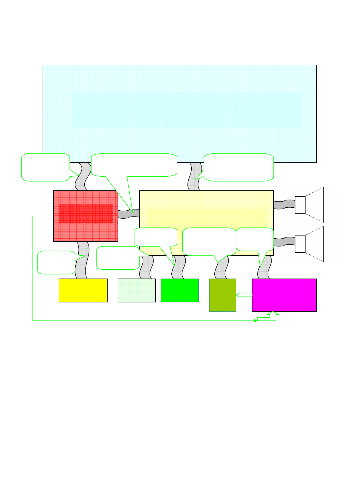
1.Diagram:
Panel CON1to
Power CON5
to Power
Input
Power Board
AC Power Input
M/B CON1 to Power CON5 ,
PowerCON4 to M/B CON2
M/B CON5
to I/B CON2
M/B CON5
to K/B CON1
KeyBoard
Panel Display
Main Board
IR Board
M/B CON6、24、
15 to DVD/B
CN6、7
LVDS Cable
M/B CON7 to panel
M/B con6
to 1556/B
DVD
Board
DVD Power Control
Board 1556
1.1 Function of Board:
1) Main Board:Control all inputing signals, Video signal decode, De-interlace, digital
Signals (LVDS signal), scaling;
2) Panel:Display all image;
3) IR Board :Recive IR Signal;
4) Power Board: Supply all the power for the TV and DVD set;
5) Key Board :POWER、SOURCE、MENU、VOL+/- ,Channel +/-, Play/Pause, Open/Close;
6) Power Switch:
Turn on/off the TV set;
2. Main Board and Power Board
2.1 Main Board and connector definition
2.1.1 Image photo
1
Page 3

Function Inverter
Connector CON8
No Signal Spec
1 ON/OFF Inverter switch
2 ADJ Adjust backlight
3 GND
4 GND
2
Function Amplifier Power
Connector CON1
No Signal Spec
1 24V 24V IN
2 24V 24V IN
3 GND
4 GND
Page 4

Function Power
Connector CON2
No Signal Spec
1 ON/OFF Power switch
2 STB5V Stand by 5V
3 5V 5V in
4 5V 5V in
5 P_Power Panel power
6 P_Power Panel power
7 GND
8 GND
9 GND
10 12V 12V in
11 12V 12V in
Function TO Keyboard & IR
Connector CON5
No Signal Spec
1 5V 5V in
2 GND
3 IR Remote single
4 LED_R
5 LED_G
6 GND
7 KEY0
8 KEY1
9 KEY
Function Power
Connector CON2
No Signal Spec
1 ON/OFF Power switch
2 STB5V Stand by 5V
3 5V 5V in
4 5V 5V in
5 P_Power Panel power
6 P_Power Panel power
7 GND
8 GND
9 GND
10 12V 12V in
11 12V 12V in
Function DVD Control
Connector CON6
No Signal Spec
1 DVD_IR Remote single
2 DVD IR_EN IR Switch
3 DVD_STB Power Switch
4 GND
2.2 Power board
2.2.1 Power board photo
3
Page 5

CON4
CON5
2.2.2 Power connecter definition
Function Inverter power
Connector CON4
No Symbol Definition
1 12V standby on/off
2 12V Stand by 5V
3 GND Ground
4 GND Ground
5 GND Ground
6 5V 5VDC out
7 5V 5VDC out
8 5VSB 5V stanby
9 STB Standby control
10 5V 5VDC out
11 5V 5VDC out
12 GND Ground
13 GND Ground
Function Main board power&control
Connector CON5
No Symbol Definition
1 GND Ground
2 GND Ground
3 GND Ground
4 GND Ground
5 24V 24VDC out
6 24V
7 24V 24VDC out
8 24V
24VDC out
24VDC out
4
Page 6

3. Hardware
3.1 Block Diagram
3.2.CV119MA frequently malfunction obviate
3.2.1.Power Defect
3.2.2.No display
3.2.3.Sound Defect
5
Page 7

M/B CON2 Pin2 no 5V?
N
Check Power Supply
N
AC Input Whether
Power LED lighting or
Y N
OK
Check the Power
Net
Y
Check L2 L3
no?
Check Line of keyboard or
LED
Fig1 Power Defect
Y
M/B CON2 Pin3/4 V=5V,Pin10/11=12V
Y
OK
N
garbage image or
No display(Back light
is micro-light)
LVDS Cable whether
insert all or no?
Y N
Panel defect ?
N Y
Change
LCD panel
Change Main Board
Change LVDS
Cable
Fig2 Display(garbage image)
6
Page 8

Blank Display
Voltage for Pan el Driving
whether normal
N Y
Change the power board
Change the main board Change the linel
Chech the line of Power to M/B
Y
N
Fig 3 No display (Blank)
7
Page 9

No sound
There are audio input or
no?
N
check
power
relevant
circuit
And
amplifier
circuit
N
Reset
again
Y
Check
speaker
Volum、MUTE set
Y
Repair main board
(U7:TPA312*)
Y
Whether normal
Y
Con3/con4 has output
Signal or no?
Check power for AMP(CON1)
N
Change power board
N
Fig5 Audio(no sound)
4. Explode
8
Page 10

9
 Loading...