

Page 1

DPRS100
SD Digital Set Top Box
DVB-T Receiver
User Manual
Page 2

2
Contents
Safety Information 3
Accessories 4
Features 5
Front Panel 6
Rear Panel 7
Remote Control Unit 8
Connecting a TV Aerial 9
Connecting to a TV 10
Connecting to a TV and VCR via A/V and RF 12
Quickstart Guide 13
Main Menu 14
TV Channel 15
Radio Channel 16
Organizing Services 17
Organizing TV Channel Menu 17
Organizing Radio Channel Menu 19
Organizing Favorite Channels 19
Clear All TV Channel 20
Clear All Radio Channel 20
Clear All Favorite Channel 20
System Setup 21
OSD Language 21
UHF Modulator 21
A/V Output 21
Time Setting 22
Parental Control 22
OSD Transparency 22
Display Time 22
Sleep Timer 22
Logical Channel Numbers (LCN) 22
Installation 23
Manual Search 23
Auto Search 24
Carrier Edit 24
Automatic Tuning 24
Factory Default 25
Information 26
Receiver Status 26
Signal Information 26
Event Timer 27
Viewing General Information 28
TELETEXT & SUBTITLE 29
EPG (Electronic Program Guide) 31
Troubleshooting 32
Technical Specification 33
Glossary 35
Page 3

3
Safety Information
• Be sure to read and understand this User Manual before starting the operation of the
receiver.
• Do not open the cover. It is dangerous to touch the inside of the receiver due to possible
electric shock hazard.
• Do not attempt to service this product by yourself. Refer all serving to qualified service
personnel.
• Disconnect the receiver from the wall outlet before cleaning it. Use only a soft dry cloth
to clean the case of the receiver.
• When the receiver is unused for a long time, please unplug the power cord from the wall
outlet.
• Do not connect or modify cables when the receiver is plugged -in. Power off the receiver
at the wall outlet before connecting or disconnecting any cables.
• Do not use a damaged power cord. Damaged power cords may cause a fire or an
electric shock.
• Do not touch a power cord with wet hands. It may cause an electric shock.
• Never stand the receiver on soft furnishings or carpets.
• For indoor use only.
• Do not use or store the receiver where it is exposed to direct sunlight or near a heater.
• Never stack other electronic equipment on top of the receiver.
• Do not use any attachments that are not recommended by the manufacturer as these
may cause hazards or damage the equipment.
• Do not expose the receiver to dripping or splashing.
• Do not place objects filled with liquids, such as vases, on the receiver.
• The ventilation should not be impeded by covering the ventilation openings with items,
such as newspapers, tablecloths, curtains etc.
• Ensure a minimum distance of 5mm around the receiver for sufficient ventilation.
• No naked flame sources, such as lighted candles, should be placed on the apparatus.
• Dispose of remote control batteries properly in accordance with local, state or federal
regulations.
General Information
This manual provides complete instructions for installing and using the receiver. All
functions of the receiver can be carried out using the buttons on the remote control, and
some of the functions can also be carried out using the buttons on the front panel.
If you have any problems with the operation of your receiver, please refer to the relevant
section of this manual or call your dealer.
Page 4

4
• User Manual
• Remote Control Unit
• Batteries: 2xAAA
• Power Cord
Accessories supplied
Page 5

5
Features
• MPEG 2 & Fully DVB Compliant
• MPEG 2 Video (MP@ ML), MPEG 1 Audio Layer 1, 2
• Double Conversion DVB-T Tuner with Loop Through Output
• Frequency Input from 177.5MHz to 858MHz (Centre Frequency)
• Fully DVB-T Compliant to EN300744
• 2k, 8k OFDM Modes
• User-friendly OSD Menu with Full Function
• 256 Colors Graphic User Interface
• Multi-language OSD Menu Support: English, German, French, Spanish, Italian, Turkish,
Arabic, Russian, Slovak and Basaha (Indonesia), Persian, Greek
• Variable Aspect Ratio 4:3 / 16:9 with Pan & Scan or Letter Box
• Advanced 7 days/24 hours EPG (Electronic Program Guide) with “extended” program
information
• Current/Next Event Guide
• Auto Update (PMT / PAT)
Customized Channels Memory Data
•
• Carriers & Frequency Table Editing with Add, Delete, Rename, Modify
• Small Screen Picture on EPG and TV Channel List Graphic (P-in-P)
• Supports TELETEXT Decoding or Re-insert into VBI
• Supports Subtitle
• Supports NTSC/PAL/SECAM
• Advanced Automatic Tuning
• 1000 TV & Radio Channels Capability
• 3 Favorites Channel Groups and Parental Lock Function
• 8 Event Timer, 120 minutes Sleep Timer
• Channel Editing with Delete, Move, Rename, Lock, Skip
• Channel Sorting
• RS232 Interface for Software Upgrading via PC directly (no Adaptor required)
• STB to STB data copy by RS232 port
PLL RF Modulator UHF 21 to 69 with PAL I / G / K and NTSC selectable.
•
• SIGNAL LED Indicator
• S/PDIF (Sony/Philips Digital Interface) for digital audio, RCA (OPTIONAL)
• Wide Range Switching Mode Power Supply (SMPS)
• Video, Audio L, Audio R Output (RCA), SPDIF output
• S-VIDEO Output
Page 6
6
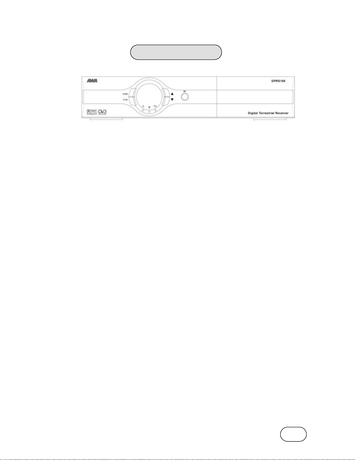
Front Panel
A. Power Button
Turns the receiver ON / OFF.
B. TV / Radio Button
Selects between TV or Radio operation mod e.
C. SIGNAL LED
Lights up with signal locked.
D. TV/RADIO LED
Lights up when in TV Mode.
E. Remote SENSOR
Detects infrared signal from Remote Control Unit.
F. POWER LED
Lights up when in STANDBY Mode.
G. CH Down Button
Change channel down.
H. CH Up Button
Change channel up .
Page 7
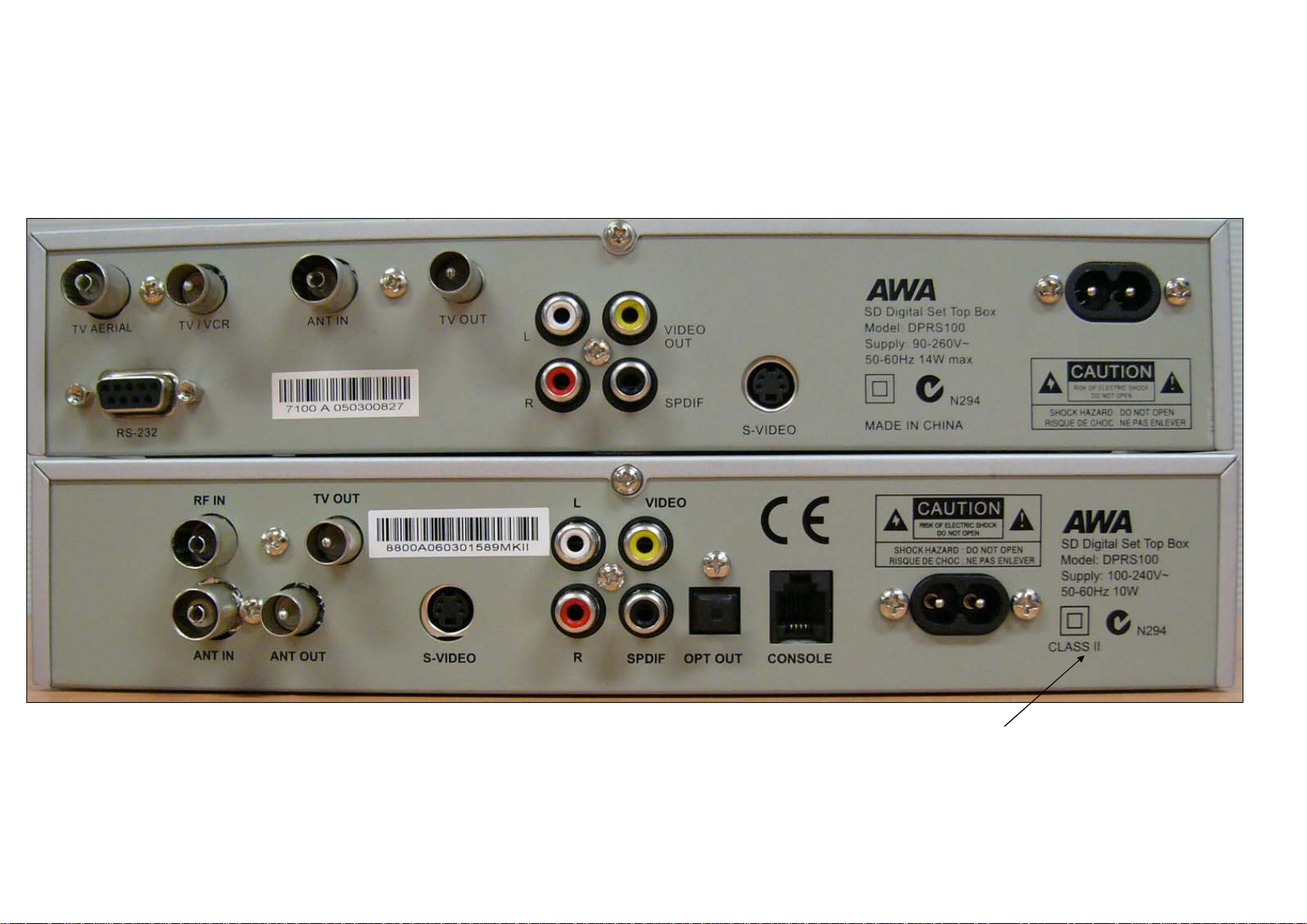
Rear Panel For Two Types of Models
DPRS100 MK I
DPRS100 MK II
Page 8
7
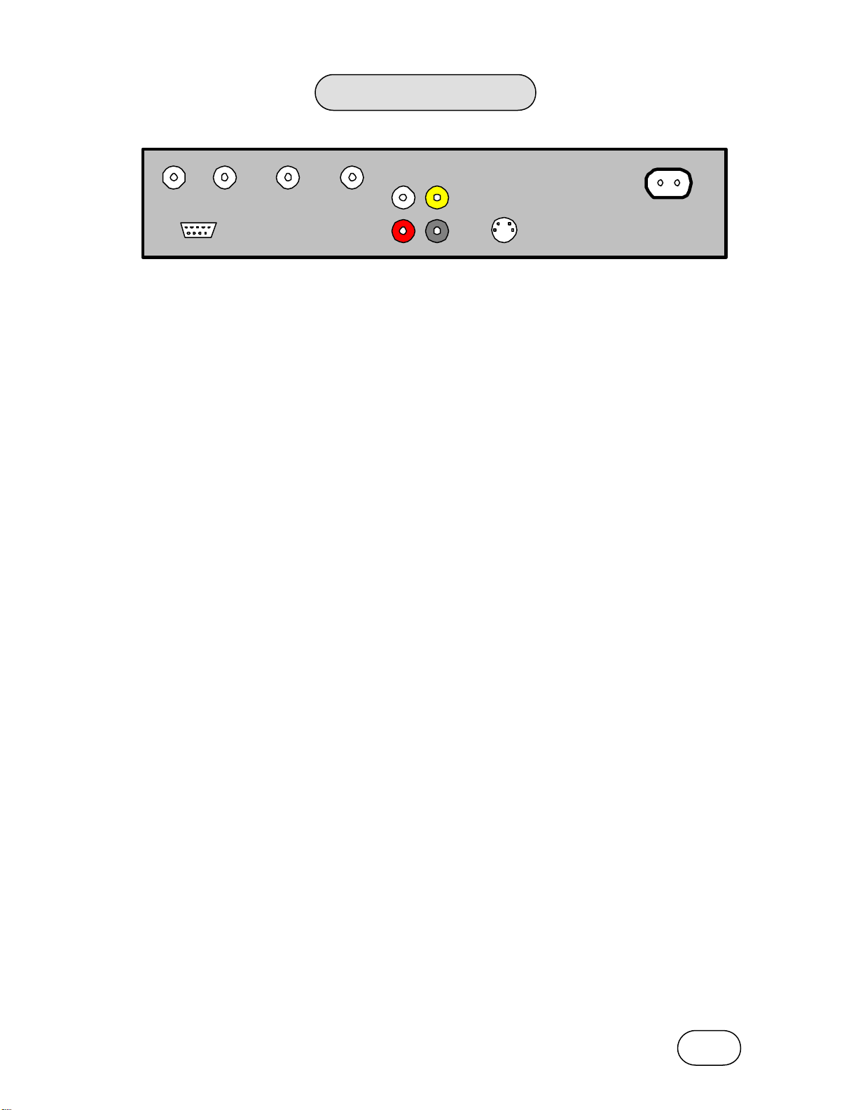
Rear Panel
TV AERIAL TV/VCR ANT IN TV OUT
RS-232
L
R
VIDEO
OUT
SPDIF
S-VIDEO
TV AERIAL (177.5 to 858 MHz)
Digital TV antenna input.
TV/VCR
Connect to the TV set or VCR RF input. (Antenna loop through)
RS-232
Used for Set Top Box software upgrades.
ANT IN
Connect to TV/VCR output to loop the RF signal through the modulator.
TV OUT (UHF Modulator output)
Connect to the TV set or VCR RF input to receive the built-in RF modulator signal.
POWER INLET
Connect this to the mains outlet (90-260V~ 50-60Hz).
AUDIO OUT (L/R)
Left, Right audio output.
S/PDIF Out
Sony/Philips Digital Interface output for digital audio.
VIDEO
Composite video output.
S-VIDEO Output
S-VIDEO output connector.
Page 9

8
Remote Control Unit
The following details the remote control buttons and their function.
1. POWER
Turns the Set T op Box On/Off.
2. TV/R
Switches between TV and Radio mode.
3. Numeric Keys (0-9)
Used for direct number input.
4.INFO
Displays the program information window.
5. EPG
Displays the Electronic Program Guide.
6. MENU
Enters the Main Menu or returns to previous Menu from
a sub Menu.
7. CH UP / DOWN (5 / 6)
Changes channels while in viewing mode and moves
the cursor up/down while in menu mode.
8. LEFT / RIGHT (3 / 4)
Changes the volume level in viewing mode and adjusts
settings while in menu mode.
9. OK
Confirms the choices and selection with the highlighted
menu item. While watching TV or listening to radio,
pressing the OK button will enter the channel list.
10. EXIT
Exit from the menu or escape from the current mode.
11. PG UP / DOWN
Move to the next or previous list/text page if more than
one page is available.
12. AUDIO
Cycle between the audio modes.
13. MUTE
Mute or un-mute the sound.
14. FAV
Enter the Favorite Channel List.
15. PAUSE
Freeze the current image on screen.
16. SYS color (Blue button)
Cycle between the video output modes.
17. UHF
Enter the UHF Modulator menu.
18. F1, F2, F3 color, Red, Yellow, Green.
Function keys 1, 2 & 3.
Page 10

9
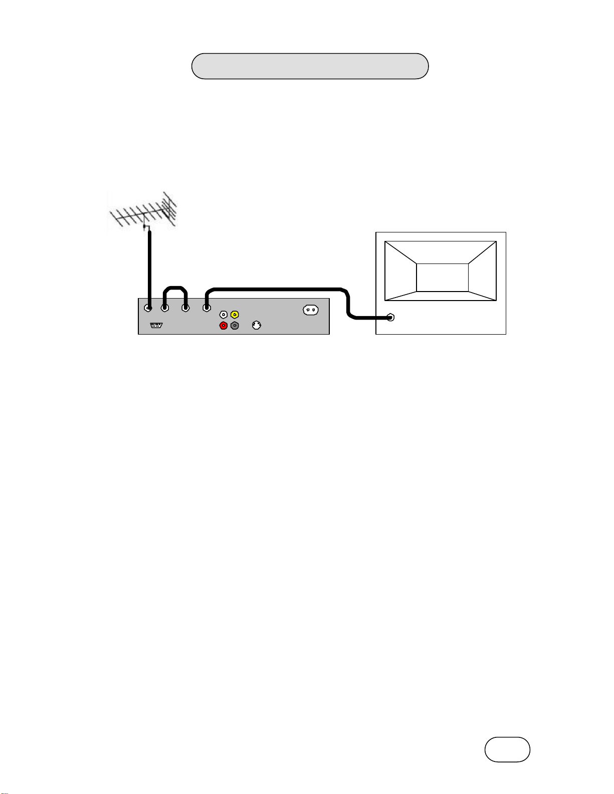
Connecting a TV Aerial
TV antenna hints
Always use a high quality digital ready outdoor VHF/UHF antenna.
It is not advisab le to use indoor or window mounted aerials, except in areas close to digital
TV transmitters, as digital channels will be difficult or even impossible to receive.
Many older aerials may only receive a limited number of channels. As a result, digital
channels transmitted on other channels are difficult or even impossible to receive. The
problem can be solved by replacing the antenna with a high quality digital ready antenna.
Some outdoor aerials are directed towards an analogue transmitter. The aerial must be
directed towards a digital TV transmitter.
It is not always advisable to position the aerial as high as possible. If problems arise,
experiment with different aerial heights.
For best results use good quality double or quad screened coax leads, and high quality
connectors throughout the TV antenna system.
Page 11
10
Connecting to a TV
There are many different types of TV/VCR and other equipment that you can connect to
your Set Top Box. Shown below are the most common methods normally used. If you have
problems wit h your connections and need help, contact your retailer.
Connecting to the TV via the RF output
Use this connection method for older TV’s that do not have an A/V input.
TV
TV AERIAL TV/VCR ANT IN TV OUT
RS-232
VIDEO
L
OUT
R
SPDIF
S-VIDEO
RF INPUT
To tune your TV to the RF signal you will also need your TV manual in addition to this
manual. The steps below explain how to make the connection. Note: RF cables are not
supplied with your Set Top Box.
• Make sure that both the TV and the Set Top Box are switched off at the power outlet.
• Connect the antenna to the TV AERIAL input of the Set Top Box.
• Connect the TV/VCR output to the ANT IN terminal on the Set Top Box.
• Connect the TV OUT output on the Set Top Box to the Antenna input of your TV.
• Turn on the Set Top Box and the TV.
• Select a program number on the TV that is not currently used (refer to TV manual).
• Follow the instructions in your TV manual to tune the TV channel selector to UHF channel
69 (this is the factory preset UHF channel in the Set Top Box).
• Follow the instructions in your TV manual to store this UHF channel. You will have to select
& use this channel number when you want to watch digital TV channels.
If the picture quality is poor, you may need to change the RF modulator output to another
channel between CH 21 and CH 69. You will also have to tune your TV to the new channel.
Please see UHF MODULATOR setting from SYSTEM MENU on page 21.
If you also have a VCR connected, the RF output of the Set Top Box must be tuned to a
different UHF channel (between CH 21 and CH 69) than the VCR.
Page 12
11
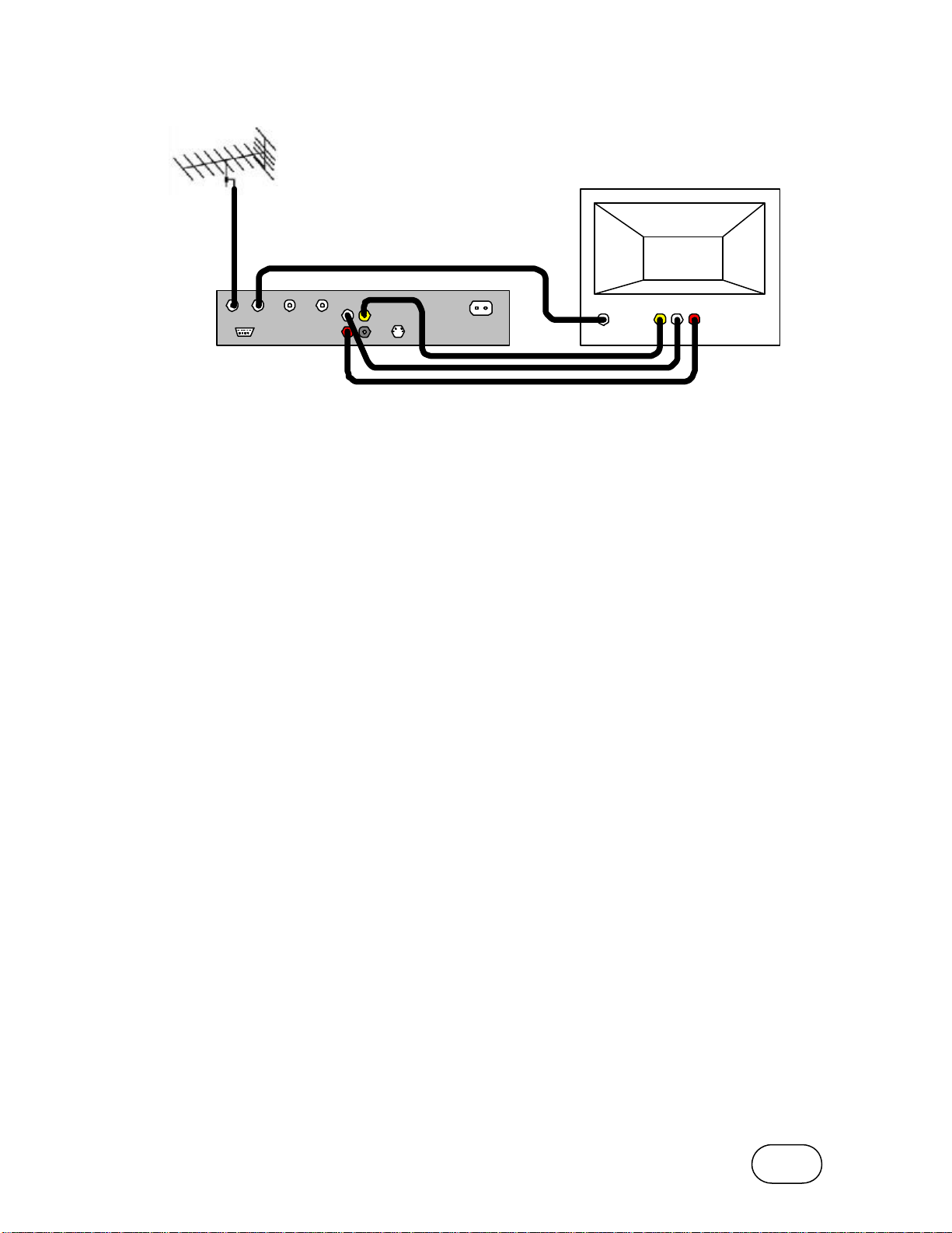
Connecting to the TV via A/V
TV
A/V INPUT
TV AERIAL TV/VCR ANT IN TV OUT
RS-232
VIDEO
L
OUT
R
SPDIF
S-VIDEO
RF INPUT
This method is recommended for the best picture quality. Note: RF, A/V and S-Video cables
are not supplied with the Set Top Box.
• Make sure that both the TV and the Set Top Box are switched off at the power outlet.
• C onnect the antenna to the TV AERIAL input of the Set Top Box.
• Connect the TV/VCR output of the Set Top Box to the RF input of the TV.
VIDEO L R
• Connect the A/V outputs of the Set Top Box to the A/V inputs of the TV.
• If your TV has an S-Video input connector, you can connect your TV to the Set Top Box
using an S-Video lead instead of the composite video lead. You must also connect the
Left and Right Audio cables in order to get sound.
• Turn on the Set Top Box and the TV.
• Select the AV input mode on the TV (refer to TV manual).
Optional audio connections
Instead of connecting the Left and Right Audio outputs to your TV, they can be connected
to your Hi-Fi stereo for better sound quality. In this case, connect the Left and Right Audio
outputs from the Set Top Box to the Left and Right Audio inputs on your Hi -Fi Stereo.
If you have a home theatre receiver with built in Dolby™ digital decoder, then connect the
SPDIF output of the digital TV Set Top Box to the SPDIF input of your home theatre
receiver.
Page 13

12
Connecting to a TV and VCR via A/V and RF
TV
TV AERIAL TV/VCR ANT IN TV OUT
RS-232
RF INPUT
RF OUTPUT VCR
L R VIDEO L R VIDEO
A/V INPUT A/V OUTPUT
VIDEO
L
OUT
R
SPDIF
S-VIDEO
RF
INPUT
A/V INPUT
L R VIDEO
This method is recommended when you wish to be able to record digital programs via the
A/V input of your VCR. This method will allow you to view programs from the Set Top Box
on the TV via the A/V inputs of the VCR, or directly from the RF modulator output of the Set
Top Box. Note: RF, A/V and S-Video cables are not supplied with the Set Top Box.
• Make sure that the TV, VCR and the Set Top Box are switched off at the power outlet.
• Connect the antenna to the TV AERIAL input of the Set Top Box.
• Connect the TV/VCR output of the Set Top Box to the RF input of the VCR.
• Connect the RF output of the VCR to the ANT IN socket of the Set Top Box.
• Connect the TV OUT output of the Set Top Box to the RF input of the TV
• Connect the A/V outputs of the Set Top Box to the A/V inputs of the VCR.
• Connect the A/V outputs of the VCR to the A/V inputs of the TV.
• Turn on the Set Top Box, VCR and the TV.
• Select a program number on the TV that is not currently used (refer to TV manual).
• Follow the instructions in your TV manual to tune the TV channel selector to UHF channel
69 (this is the factory preset UHF channel in the Set Top Box).
Note: The RF output of the Set Top Box must be tuned to a different UHF channel
(between CH 21 and CH 69) than the VCR.
• Follow the instructions in your TV manual to store this UHF channel. You will have to select
& use this channel number when you want to watch digital TV channels.
• View the Set Top Box directly using the new channel tuned on the TV, or
• View the Set Top Box via the VCR by selecting the A/V input channel on the VCR and
on the TV.
If the picture quality is poor, you may need to change the RF modulator output to another
channel between CH 21 and CH 69. You will also have to tune your TV to the new channel.
Please see UHF MODULATOR setting from SYSTEM MENU on page 21.
Page 14

13
Quickstart Guide
Once you have connected the Set Top Box to your TV, use the following guide to tune in the
local digital TV stations. If you have not yet connected your Set Top Box to a TV then
please refer to the ‘Connecting to a TV’ section beginning on Page 10. Advanced
operations are covered in the Main Menu section starting on Page 14.
• Ensure that the Set Top Box and your TV are switched on.
• Select the appropriate input on your TV to view the Set Top Box output signal.
• Enter the Main Menu on the Set Top Box by pressing the MENU button on the remote
control.
• Use the Down ( 6) button to highlight the SYSTEM SETUP menu bar. Press OK to enter
the SYSTEM SETUP menu.
• Use the Down ( 6) button to highlight the TIME SETTING menu bar. Press OK to enter
the TIME SETTING menu.
• Use the Down ( 6) button to highlight the MODE menu bar. Use the V-/V+ (3/4) buttons
to select the AUTO mode.
• Use the Down (6) button to highlight the LOCATION menu bar. Use the V-/V+ (3/4)
buttons to select the state where you are u sing the Set Top Box.
• Press MENU to save the settings and return to the SYSTEM SETUP menu.
• Press MENU to return to the Main Menu.
• Use the Down (6) button to highlight the INSTALLATION menu bar. Press OK to enter
the INSTALLATION menu.
• Use the Down ( 6) button to highlight the AUTOMATIC TUNING menu bar. Press OK to
enter the AUTOMATIC TUNING menu.
• Press OK to begin the AUTOMATIC TUNING process.
• The Set Top Box will scan the entire TV band looking for available digital TV carriers.
Once the Set Top Box has sca nned the entire TV band, it will enter the Channel Search
•
mode to locate the available digital TV channels.
• When the Channel Search finishes, a window will appear showing how many channels
were found during the search. Press OK to store the new channels in the Channel List.
• Press EXIT to close the window and store the channels.
• Wait for the INFORMATION window to close, and then press EXIT to leave the menus.
• Your Set Top Box should now be ready to view the digital TV channels available in your
area. For advanced viewing functions, please refer to the detailed menu instructions in
the next section.
Page 15

14
Main Menu
This chapter assumes that the Set Top Box has been installed correctly as detailed in the
previous sections.
If the Set Top Box has not been installed or connected properly, please refer to the
Connecting to TV Aerial & Connecting to TV sections of this manual.
Press the MENU button on remote control to enter the Main Menu. The following buttons
are used in the menus to allow you to access and change the functions available. Note that
the Set Top Box also indicates the actual function of these buttons for a particular menu on
the blue bar shown at the bottom of the screen.
Press the Up/Down (5/ 6) button to move the cursor.
Press the V-/V+ ( 3/4) buttons to select or adjust the current setting.
Press the Double arrow Up/Down button on the remote control to jump to the next page.
Press OK to select the item currently highlighted by the cursor, or to save the current setting.
Press EXIT to leave the current Menu or Sub Menu.
The Set Top Box may request you to input the correct password when the Parental Control
is switched ON. (Refer to PARENTAL Control section, page 22). The default password is
“0000”.
Page 16

15
TV Channel
You can access the TV Channel List by selecting TV CHANNEL from the Main Menu and
pressing the OK button.
Press the Up/Down (5/ 6) button to move the cursor. If you press OK button on the desired
channel, you can watch the channel from the small screen. The channel currently being
viewed in the small screen will have the channel number highlighted in the TV Channel list.
Under the small picture screen, the following information is displayed:
1. Carrier frequency
2. Guard Interval
3. Transmission Mode / FFT
4. Constellation
5. Puncture Rate / FEC
6. Hierarchy Mode
7. VPID, APID, PCR
8. SIGNAL LEVEL Indicator
9. SIGNAL QUALITY Indicator
Press the Double arrow Up/Down button on the remote control to jump to the next page.
Press EXIT to return to normal viewing, or press MENU to return to the Main Menu.
Page 17

16
Radio Channel
You can access the Radio Channel List by selecting RADIO CHANNEL from the Main
Menu and pressing the OK button.
Press the Up/Down (5/ 6) button to move the cursor. If you press OK button on the desired
channel, you can listen to the services. The channel currently being listened to will have the
channel number highlighted in the Radio Channel list.
Under the small picture screen, it displays also the receiving parameters such as:
1. Frequency
2. Guard Interval
3. Transmission Mode / FFT
4. Constellation
5. Puncture Rate / FEC
6. Hierarchy Mode
7. APID, PCR
8. SIGNAL LEVEL Indication bar
9. SIGNAL QUALITY Indication bar
Press the Double arrow Up/Down button on the remote control to jump to the next page.
Press EXIT to return to normal viewing, or press MENU to return to the Main Menu.
Page 18

17
Organizing Services
From the Organizing Services Menu, you can
access the following sub menus:
1. TV CHANNEL
2. RADIO CHANNEL
3. FAVOURITE LIST
4. CLEAR ALL TV CHANNEL
5. CLEAR ALL RADIO CHANNEL
6. CLEAR ALL FAVOURITE LIST
ORGANIZING TV CHANNEL MENU
This Menu allows you to Delete, Move, Rename,
Lock, Skip and Sort the available TV channels.
Press V-/V+ (3/4) to select the required function
as indicated across the top of the screen.
Press Up/Down ( 5/6) to move the cursor in the
channel list.
Press OK to select or deselect chann els from
the channel list.
Press MENU to process the selections and exit.
Press EXIT to exit the menu without making any
changes.
è To DELETE a channel
Press V-/V+ (3/4) buttons to select DELETE.
Press OK to select the channel(s) to be deleted
from the list. Press OK on a highlighted channel
to de-select it.
Selected channels will have the channel number
highlighted. You can select more than one
channel at a time to be deleted.
Press MENU to delete the highlighted channels.
è To MOVE a channel
Pre ss V-/V+ (3/4) buttons to select MOVE.
Select the channel you want to move with the
OK button. Key -in the channel number where
you want to move the selected channel to in the
channel list.
Press the OK button to place the channel into
the new position.
Note: The move function will not work if the
Logical Channel Number option is switched on.
(See page 22)
Page 19

18
è To RENAME a channel
Press V-/V+ (3/4) buttons to select RENAME.
Select the channel you want to rename with the
OK button.
The Alphabet Table will appear. Enter in the
desired channel name by using the Up/Down
(5/6), V-/V+ ( 3/4) and OK buttons.
Numbers can be entered into the new channel
name by using the numeric keys on the Remote
Control Unit.
Select “SAVE” to save the new channel name.
è To LOCK a channel
Press V-/V+ (3/4) buttons to select LOCK.
Press OK to lock the selected channel from the
channel list. Press OK on a locked channel to
unlock it.
The Ï icon is shown for channels that are
locked.
All locked channels will require the PIN Code to
be entered in order to view the channel. The
ACCESS CONTROL must be set to ON in order
for the lock function to work. Refer to Page 22.
è To SKIP a channel
Press V-/V+ (3/4) buttons to select SKIP.
Press OK to turn on the skip function for the
selected channel. Press OK on a channel with
the skip icon to turn it off.
The 8 icon is shown for channels that will be
skipped.
è To change the order of the CHANNELS
Press V-/V+ (3/4) buttons to select SORT.
Press OK to bring up the CH SORTING window.
Move the cursor and press OK to select the
required sorting criteria.
LOCK / UNLOCK: Will line up all the Locked or
Unlocked channels at the beginning of the list.
A-Z / Z-A: To arrange the channels by
alphabetic order from A to Z or from Z to A.
CARRIER: To arrange the channels by
frequency in ascending order.
NETWORK: To arrange channels in the
alphabetic order of the network name.
Press MENU to sort the channel list as per the
selected criteria.
Note: The sort function will not work if the
Logical Channel Number option is switched on.
(See page 22)
Page 20

19
ORGANIZING RADIO CHANNEL MENU
This menu allows you to Delete, Move, Rename,
Lock, Skip and Sort the available radio
channels.
Radio channels can be Deleted, Moved,
Renamed, Locked, Skipped and Sorted in the
same man ner as the ORGANIZING TV
CHANNEL MENU. Refer to the previous two
pages for more detail.
ORGANIZING FAVOURITE LIST
There are 3 favourite lists available for you to
store your favourite channels.
Press the INFO button to switch between the
three favourite groups.
You can select any available channel from the
list in the left hand side of the screen and put in
into your favourite channel list on the right hand
side of the screen.
You can assign any channel to any one of the
favourite groups 1, 2 or 3.
Use t he cursor to select the desired channel and
press OK to store it in the favourite list.
Use the cursor to select any of the favourite
channels and press OK to remove it from the
favourite list.
Page 21

20
CLEAR ALL TV CHANNELS
Use this function to clear all of the stored TV
channels from the TV channel list.
The confirmation window will appear. If you
select the Yes, then all of the available TV
channels will be erased.
CLEAR ALL RADIO CHANNEL
Use this function to clear all of the stored Radio
channels from the Radio channel list.
The confirmation window will appear. If you
select the Yes, then all of the available Radio
channels will be erased.
CLEAR ALL FAVOURITE LIST
Use this function to clear all of the stored
Favourite channels from the favourite groups.
The confirmation window will appear. If you
select the Yes, then all of the favourite channel
lists will be erased.
Page 22

21
System Setup
From the System Setup Menu, you can access
the following sub menus:
1. LANGUAGE
2. UHF MODULATOR
3. A/V OUTPUT
4. TIME SETTING
5. PARENTAL CONTROL
6. OSD TRANSPARENCY
7. DISPLAY TIME
8. SLEEP TIMER
9. LCN (logical Channel Numbers)
OSD LANGUAGE
There are 12 available languages for the OSD
Menus.
The default language is English.
Use the cursor to select the desired language
and press OK to sele ct.
UHF MODULATOR
à CHANNEL NO.
Select the RF modulator output UHF channel.
The default channel is set to CH69.
à STANDARD
Select the audio sound system standard. You
can select PAL B/G, PAL I, PAL D/K or NTSC M.
The default setting is PAL B/G.
Press MENU to save and exit.
A/V OUTPUT
à VIDEO OUTPUT
Select the Video Output according to your TV.
The Set Top Box converts the input signal into
any one of the selected signal formats. You can
select AUTO, PAL, PAL M, PAL N, SECAM.
à
AUDIO MODE
Select the sound mode to Stereo, Mono L, and
Mono R.
à TV ASPECT RATIO
Set the screen format of the TV. 4:3 Full screen,
4:3 Letterbox or 16:9.
Press MENU to save and exit.
Page 23

22
TIME SETTING
à LOCAL TIME
The Local Time can only be adjusted when the
Time Mode is set to Manual. Adjust the time by
using the numeric buttons.
à MODE
The Auto mode automatically updates the time
setting by adding the GMT received from the
DVB-T Carrier and the Time Offset value you
have inserted. The Auto mode is recommended.
à LOCATION
Select your current location in order to set the
correct time offset value.
Select USER to enter the time offset manually.
PARENTAL CONTROL
à
ACCESS CONTROL
Controls access to some of the Main Menu
functions and locked channels. When set to ON,
you must enter the PIN code before entering the
Organizing Services, Installation and Event
Timer sub menus.
à CHANGE PIN CODE
Use this function to change the parental control
PIN Code.
The default PIN code is “0000”.
OSD TRANSPARENCY
Adjust the OSD transparency level. The
transparency can be adjusted between 10% and
90%.
DISPLAY TIME
Set the period of time that the Info Box is
displayed on screen. The time steps available
are 3, 5, 8, 10, and 15 seconds.
SLEEP TIMER
Set the sleep timer between 15 and 120
minutes. The Set Top Box will automatically
switch to standby after this time has elapsed.
A reminder will appear when there is 1 minute
left before sleep timer shutdown.
LCN (Logical Channel Number) Set up:
Turn on LCN to force the channel list to be
arranged in Logical Channel Number order. The
logical channel numbers are defined by the TV
networks in your area.
Page 24

23
Installation
From the Installation Menu, you can access the
following sub menus:
1. COUNTRY
2. BANDWIDTH
3. MANUAL SEARCH
4. AUTO SEARCH
5. CARRIER EDIT
6. AUTOMATIC TUNING
7. FACTORY DEFAULT
COUNTRY
Set the country where the Set Top Box is being
used. The Default is Australia.
BANDWIDTH
Select the correct bandwidth for the TV carrier:
6MHz for USA
7MHz for Australia or Europe (Default)
8MHz for Europe, Asian countries
Digital TV channels and Multichannelling
Digital TV allows network operators to broadcast more than one channel per carrier
(Multichannelling). Your Set Top Box stores each network’s carrier information in the Carrier
List. The Carrier List contains information such as Carrier Center Frequency, Guard Interval
and Modulation system. The Channels contained within each Network Carrier are stored in
the TV and Radio Channel Lists. The first time you set-up your Set Top Box, you will need
to scan the entire TV band in your area to find all of the available digital TV carriers, and
then scan those carriers for the available channels. The Automatic Tuning process
performs these two steps automatically.
MANUAL SEARCH
Use the MANUAL SEARCH to re-scan the
available channels from one network carrier.
à CARRIER CHANNEL
Select the charier channel to be re-scanned.
à FREQUNECY
Enter the correct center frequency of the carrier
channel by using the numeric buttons on the
remote control, in kHz (6 digits).
à NETWORK SERACH
Set to ON in order to search other carriers
belonging to the same network.
Page 25

24
AUTO SEARCH
Use Auto Search to re -scan all of the available
channels from the current Carrier List. The Auto
Search will start automatically when you press
OK to select the Auto Search sub menu.
During the search, channels located will appear
in the Channel Search window.
When the Auto Search finishes, a window will
appear showing how many channels were found
during the search. Press OK to store the new
channels in the channel list, or EXIT to exit the
menu without saving the new channels.
CARRIER EDIT
This menu allows you to edit the Carrier List.
Press OK to bring up the
ADD/DELETE/MODIFY window.
Follow the on-screen prompts to make the
desired changes.
AUTOMATIC TUNING
The Automatic Tuning process will scan the
entire TV band, within the limits of the VHF and
UHF start and end frequencies. For Australia the
default settings are:
VHF Start Frequency: 177500kHz
VHF End Frequency: 226500kHz
UHF Start Frequency: 529500kHz
UHF End Frequency 816500kHz
Press OK to start the Automatic Tuning process.
The AUTOMATIC TUNING window will appear,
and a list of available digital broadcast carriers
will appear as they are found during the search.
Once the entire TV band has been scanned, the
CHANNEL SEARCH window will appear. All of
the carriers located in the AUTOAMTIC TUNING
window will be searched to find all of the
available TV and Radio channels.
When the Channel Search finishes, a window
will appear showing how many channels were
found during the search. Press OK to store the
new channels in the Channel List, or EXIT to exit
the menu without saving the new channels.
Page 26

25
FACTORY DEFAULT
All of the stored channels, carriers and favourite
lists will be deleted after you select this option.
Select your country from the Country List and
press OK.
All menu settings and options will be restored to
the factory defaults for the selected country.
Page 27

26
Information
The Information Menu allows you to check:
1. Receiver Status
2. Signal Information
RECEIVER STATUS
The following system information is displayed:
• Hardware Version
Software Version
•
• Loader Version
• Application
• Software Last Update
SIGNAL INFORMATION
This menu allows you to check the following
parameters relating to the signal currently being
received by the Set Top Box:
• CARRIER FREQUENCY
• GUARD INTERVAL
• FFT
• CONSTELLATION (Modulation)
• PUNCTURE RATE (FEC)
• MODE
• PID = VPID / APID / PCR
• SERVICES NAME (PROVIDER)
• SYSTEM NAME
• SIGNAL LEVEL
• SIGNAL QUALITY
Note: You must select the channel for which you
wish to view the signal information, before
entering the Signal Information menu.
Page 28

27
Event Timer
The Event Timer allows you to set up the
Set Top Box to turn on and off
automatically. Up to eight programmed
events can be entered for automatic
operation.
à EVENT NO.
Select the required event number.
à MODE
Select the desired operation mode:
Once, Daily, Weekly, Monthly, Off
à DATE
Enter the event starting date.
à START TIME
Enter the event starting time
à Duration
Enter the event duration
à CHANNEL NO.
Enter the channel number required for the
event
à ACTIVE
Set to YES to activate the current event.
à OK
Press “OK” Key each time Event Timer is
set
Page 29

28
Viewing General Information
This section provides general information about watching digital TV or listening to digital
radio.
PROGRAM INFORMATION
Whenever you press INFO button, the program information window will appear on the
bottom of screen for few seconds. The following icons will be displayed depending on the
Set Top Box settings and the available channel’s services.
‘ - Scrambled services
Y - Favorite channel
•
- Teletext / Subtitle services are available
Ï - Locked channel
XW 1/1 - Current Audio Mode & Audio Channel of total available audio channelsAlso
displayed are the receiving parameters, Signal quality, Date & Clock. Pressing the INFO
button again will show the program detail information. Use the V-/V+ (3/4) buttons to
cycle between the current and next event details.
When listening to radio programs, the screen will display a still picture as the background
and the program information window will appear on the bottom of the screen.
AUDIO TRACK SELECTION
While watching TV or listening to Radio, press
the AUDIO button to select other audio sound
tracks if available.
Use the V-/V+ (3/4) buttons to cycle the audio
mode between Stereo, Mono L, and Mono R.
Page 30

29
TV & RADIO CHANNEL LIST
While watching the TV or listening to the Radio, you can access the channel list by pressing
the OK button on the Remote Control. Press the Up/Down (5/6) buttons to move the
cursor. Press the OK button on the desired channel to watch the channel on the small
screen. Press the EXIT button to return to normal viewing.
F AVORITE CHANNEL LIST
When watching the TV or listening to the Radio
you can access the favorite channel lists by
pressing the FAV button on the remote control.
Use V-/V+ (3/4) buttons to cycle between the
three favourite lists.
VOLUME CONTROL
Use 3/ 4 (V-/V+) button to decrease or increase
the output volume level.
Press MUTE button to decrease the volume to
Zero.
Press MUTE again to resume the previous
volume level.
Page 31

30
SUBTITLES
To activate the subtitles press the F2 button on
the remote control.
Press the F2 button when subtitles are on to
bring up the Teletext-Subtitle window. Use 3/4
(V-/V+) buttons to select OFF and press OK to
turn off the subtitles.
TELETEXT
To activate teletext press the F1 button on the
remote control.
Use the numeric keys on the remote control to
navigate through the teletext pages.
Press EXIT to close teletext.
Page 32

31
Electronic Program Guide
Press the EPG button on the remote control to
access the Electronic Program Guide (EPG).
Press Up/Down (5/ 6) to select a channel. A
preview of the channel will appear in the small
window.
Press V -/V+ (3/4) to select the day. The program
guide for the selected day will appear in the lower
window.
Press F1 to move the cursor to the lower
window.
Press Up/Down (5/6) to select the desired
program and press OK to view the program
information.
Press F2 to enter an event for the selected
program.
Page 33

32
Troubleshooting
ged in to the wall outlet, and
Check that power is available from the wall outlet using a portable
tions between the Set Top Box
Check that if you have selected the correct channel or A/V input on
Check the A/V and/or RF connections between the Set Top Box
Check the antenna cable to the Set Top Box for damage or loose
Check for interference from any other devices connected between
Check the “Signal Level & Quality” in the Information / Signal
Top
If you experience difficulty when operating the Set Top Box, check the following items
before calling for service.
If you can’t solve the problem even after referring this troubleshooting guide, please call the
Dick Smith Electronics Customer Support Hotline on 1300 660054.
PROBLEM SOLUTION
The indicators on the
front panel do not
illuminate
No picture Ensure the Set Top Box is switched on.
No sound Check the volume level of the TV & Set Top Box.
Remote Control
doesn’t operate
No or Bad signal
Check that the power cable is plug
that the wall outlet is switched on.
desk lamp or other portable appliance.
Check the A/V and/or RF connec
and the TV.
Check that the TV is switched on and set up properly.
your TV.
Check that the antenna is correctly connected to the Set Top Box.
and the TV.
Check the MUTE status of the TV & Set Top Box.
Point Remote Control directly towards the Set Top Box.
Check and replace batteries if necessary.
connections.
Set the value of tuner parameters correctly in the Installation Menu.
Check the position of the antenna – realign antenna if necessary.
antenna and the Set Top Box.
Status Menu.
Forget PIN Code Contact the Set Top Box service agent in order to reset the Set
Box.
Page 34

33
Technical Specifications
3 MPEG 1 Layer I & II, ISO/IEC
= TUNER & DEMODULATOR
Input Frequency : VHF Frequency 177.5 MHz to 227.5 MHz
UHF Frequency 474 MHz to 858 MHz
Input Power Range : -80 to -35 dBm
Input Connector : Female, 75 ohm
Output Connector : Male, 75 ohm
IF Bandwidth (IF BW) : 6MHz, 7MHz or 8MHz
Center Frequency : 36MHz
Demodulation : COFDM
FEC : AUTO, 1/2, 2/3, 3/4, 5/6, 7/8
Mode (FFT) : 2k, 8k
Constellations : QPSK, 16QAM, 64QAM
Hierarchy Mode : No-Hierarchical, Hierarchical
Codes Rates : 1/2, 2/3, 3/4, 5/6, 7/8
Guard Intervals : 1/4, 1/8, 1/16, 1/32
Symbol Rate, MS/s : 4.354 (IF BW = 7MHz) to 31.67 (IF BW = 8MHz)
Eb/No Performance : Exceeds DVB rec.
= VIDEO DECODE
Decoding : MPEG-2 MP@ML, ISO/IEC 13818 -2, 11172-2
Data Rate : Max 15Mbit/s
TV Standard : Auto PAL, NTSC and SECAM according to Source
Aspect Ratio : 4:3, 16:9
Active Pixel : 720 x 576 (PAL), 720 x 480 (NTSC) maximum
Output Level : 1Vpp +/-10%
Bandwidth : 100Hz to 5MHz +/-2dB
S/N : 55 dB min
C/L Delay : +/- 75 nS
DG : 5% max
DP : 5° max
Line Time Distortion : 3% max
Field Time Distortion : 5% max
= AUDIO DECODE
Decoding : ISO/IEC 11172Sampling Frequency : 32, 44.1, 48 kHz
Peak Output Level : 2.0Vrms into 600ohm
Audio Mode : Stereo, Dual Channel, joint Stereo, Mono-L, Mono-R
Frequency Response : <2dB (15Hz to 20kHz)
THD : <0.3% maximum
13818-3 MPEG 2 Layer I & II
Page 35

34
= RF PLL MODULATOR
Dolby
Antenna Input : 47 to 862 MHz
Input Connector : Female, 75 ohm
RF Output CH : UHF 21 to 69
Output Level : 72dBuV typ
Audio System : PAL I, PAL G, PAL K, NTSC M selectable by MENU
Output Connector : Male, 75 ohm
= A/V & Data Port
VIDEO : CVBS / RCA connector
S-VIDEO : Y/C, Mini-DIN
AUDIO R/L : RCA/Cinch Audio Out
(Resolution: 16 bits DAC, Max. 2 Vrms)
SPDIF : RCA/Cinch, SPDIF Digital Audio Output for
AC3, MPEG BitStream
RS232 Data Port : Transfer rate 115,200 bps,
9pin D-sub Female Type
= FRONT PANEL & DISPLAY
4 Keys : Power, TV/Radio, Channel Up, Channel Down
POWER LED (RED) : Lights up when in Standby
Flashes when remote control operates
SIGNAL LED (AMBER) : Lights up when locked onto a signal
TV/Radio LED (GREEN) : Lights up when in TV mode
= POWER SUPPLY
Input Voltage : 90 to 260 VAC
Input Frequency : 50/60 Hz
Input Rating : 1.0 A maxi mum
Power Consumption : 14W maximum, <8W Standby
Operating Temperature : 0ºC to 45ºC
Storage Temperature : -40ºC to 65ºC
= WEIGHT & DIMENSION
Weight : 1.5kg approx
Dimension : 255 (W) x 206 (D) x 50 (H) mm
Page 36

35
Glossary
APID
Audio Packet Identifier
BER
Bit Error Rate. Used as a measure of the digital signal quality
Electronic Program Guide (EPG)
An EPG is the electronic version of a printed program guide
Forward Error Correction (FEC)
A system of error control for data transmission
Frequency
The number of cycles or events per one second, which is expressed in the unit of Hertz
(Hz)
FTA
Free To Air
kHz
Kilohertz – The prefix kilo means thousand, i.e. 1,000Hz
MHz
Megahertz – The prefix mega means million, i.e. 1,000,000Hz
MPEG
Moving Picture Experts Group. Established by the International Standards Organization,
which has and continues to develop Standards for digital compressed moving pictures and
associated audio.
OSD
On Screen Display
Packet Identifier (PID)
A unique integer value used to identify elementary streams of a program in a single or
multi-program MPEG-2 stream.
PAL, NTSC and SECAM
Standards for encoding colour in an analogue TV signal
PCR
Program Clock Reference
Symbol Rate
Speed of the digital package transmission
SPDIF
Sony/Philips digital interface format. Digital audio output.
Ultra High Frequency (UHF)
A defined frequency range of Radio frequency for TV broadcasting
Very High Frequency (VHF)
A defined frequency range of Radio frequency for TV broadcasting
VPID
Video Packet Identifier
Page 37

36
AWA Edition – January 2005
a Copyright 2005
All rights reserved. Reproduction or publication of the content in any manner, without
express written permission of the publisher, is prohibited.
The Menu structure and Specifications may change without prior notice.
 Loading...