

Page 1
LED TV
control User Manual
ATTENT IO N!
Pleas e rea d this ma nua l ca ref ully be for e insta lli ng or ope rat ing the TV.
Keep th is ma nual ha ndy f or f urt her r ef ere nce.
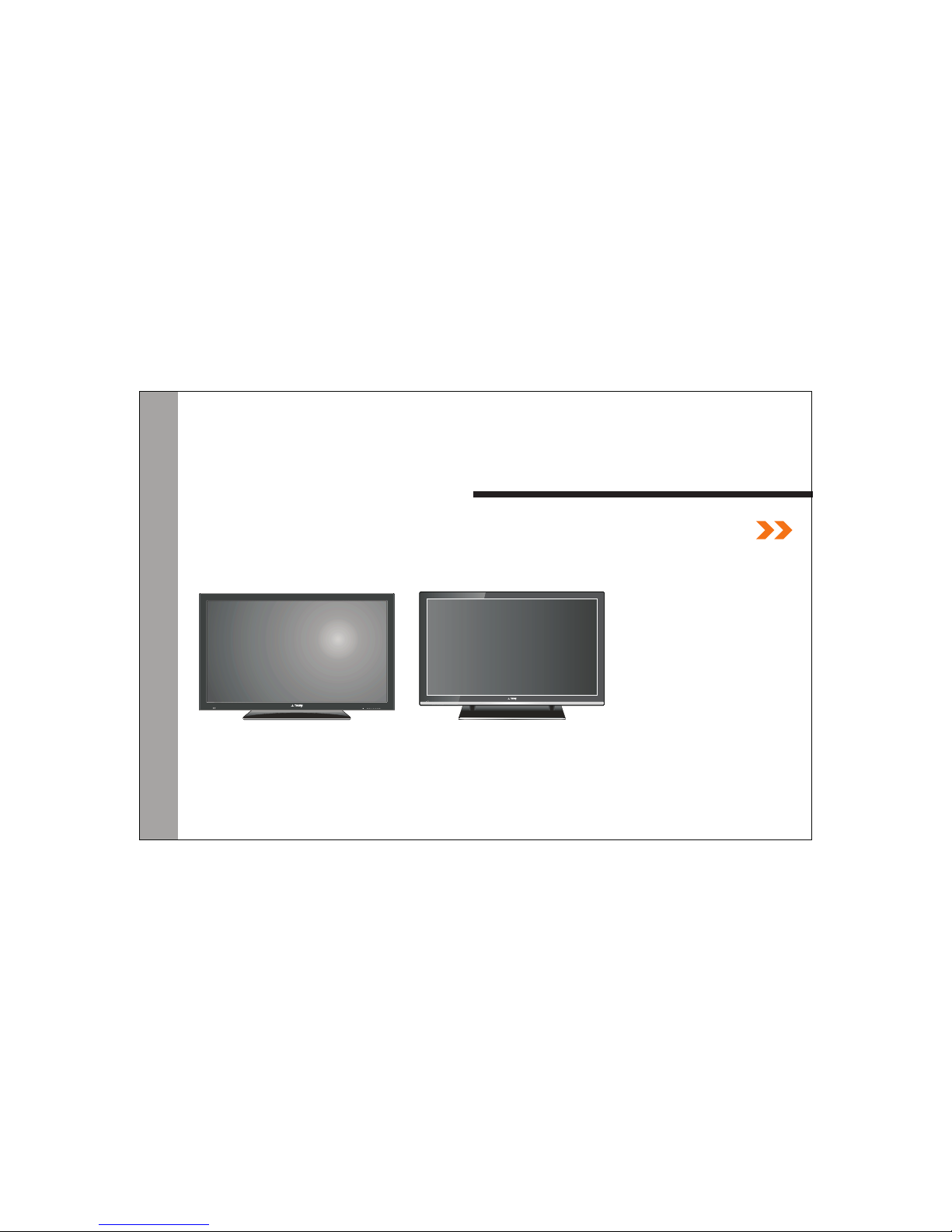
65THLCHD2
MODEL: 55THLCHD3
Page 2

CONTENTS
1.
Warn ings and cau tions
3.
4.
5.
6.
7.
.
Introduct ion
2.
......... ..... ... ......... ..... ... 1
. ......... ........... ......... .. ......... ........... ........... ........... ......2
......... ........... ......... .. ......... .. ......... ........... ........... .
......... ........... ......... .. ......... .. ......... ........... ........... ........... ......... 9
......... ........... ......... .. ......... .. ..
......... ......
......... ........... ......... .. .........
......... ........... ......... .. ......... .. ......... ........... ........... ....
.. ......... ........... ......... .. .. ......... ........ ..... ......... .. ......
.... ......
......... ...... ...5
......... ...... ......11
......... ...... .12
......... ... .......17
8 ......... ...... ......... 32
Main unit de scription s
Televi sion Installation
The b asic view of Remo te Co nt rol b oard
Operation and Func tion Descr ip tion of K eys on Re mo te Control
Operation and Fu nction Des cription o f Menu
Tro ubleshoot ing
Page 3

Int r oduct ion
Thank y ou for ch oosin g our pro duct. You ca n use it as a n LED tel evisi on or as a PC m onitor. To be able to
make us e of all ap plica tion op tions, we co mmend t hat you r ead thi s opera ting ma nual ca reful ly and ke ep
it some where w here yo u have qu ick access t o it, if re quire d.
Do not to uch any p arts in t he set an d do not make ch anges t o any set tings n ot desc ribed i n this op erati ng
manua l.
Installation
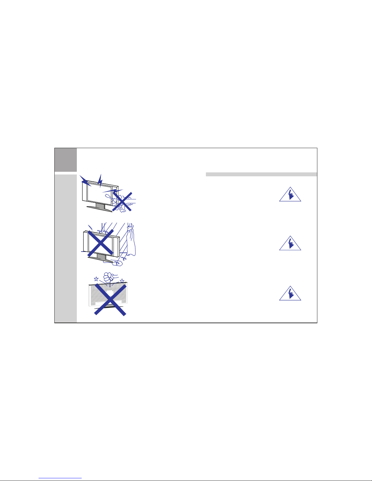
Locat e the rec eiver i n the roo m where dire ct ligh t does no t strik e the scr een.
Tota l darkn ess or a re flect ion on th e pictu re screen ca n cause e yestr ain.
Soft an d indir ect lig hting i s recommen ded for c omfor table v iewin g.
Allow e nough s pace be tween t he receive r and the w all to pe rmit ve ntila tion.
Avoi d exces sivel y warm lo catio ns to preven t possi ble dam age to th e cabin et or pre matur e compo nent
failu re.
This TV receive r can be co nnect ed to AC Volts. 5 0/60 Hz . Never c onnec t to DC supply o r any
other p ower su pply.
Do not in stall t he rece iver in a l ocation ne ar heat s ource s such as r adiat or, air du cts, di rect su nligh t, or in
a place s omewh ere lik e close c ompartme nt and cl ose are a.
Do not co ver the v entil ation o penings wh en usin g the set .
Caution
Never t amper w ith any c ompon ents insid e your se t, or any o ther ad justm ent con trols n ot ment ioned i n
this ma nual.
100~2 40
1
Page 4
War nin gs and ca ution s
Warning
High vo ltage s are use d in the op eration of t his pro duct.
Do not re move th e back co ver of th e cabinet. R efer se rvici ng to
quali fied se rvice p erson nel.
Warning
To pre vent fi re or ele ctric al shoc k hazar d, do not expo se the ma in
unit to r ain or mo istur e.
Warning
Do not dr op or pus h objec ts into t he televis ion cab inet sl ots or
openi ngs. Ne ver spi ll any ki nd of liquid o n the tel evisi on rece iver.
2
Page 5
!
!
!
War nin gs and ca ution s
Caution
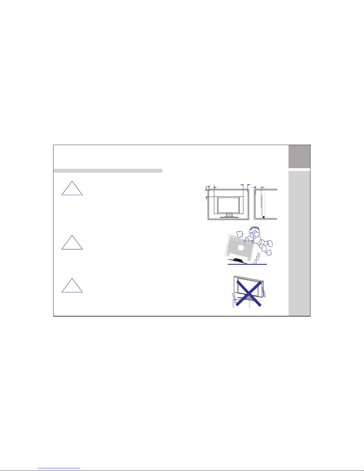
If the te levis ion is to b e built i nto a compar tment o r
simil arly en close d, the mi nimum dist ances m ust be
maint ained .
Heat bu ild-u p can red uce the s ervice lif e of your
telev ision , and can a lso be da ngerous.
Heat bu ild-u p can red uce the s ervice lif e of your
telev ision , and can a lso be da ngerous.
Caution
Never s tand on , lean on , push su ddenly the p roduc t or its st and.
You shoul d pay spe cial at tenti on to childr en.
Caution
Do not pl ace the m ain uni t on an uns table cart s tand, s helf or t able.
Serio us inju ry to an in divid ual, and dam age to th e telev ision , may
resul t if it sho uld fal l.
Min imum di stanc es
10c m
20c m
10c m
5cm
3
Page 6
War nin gs and ca ution s
Caution
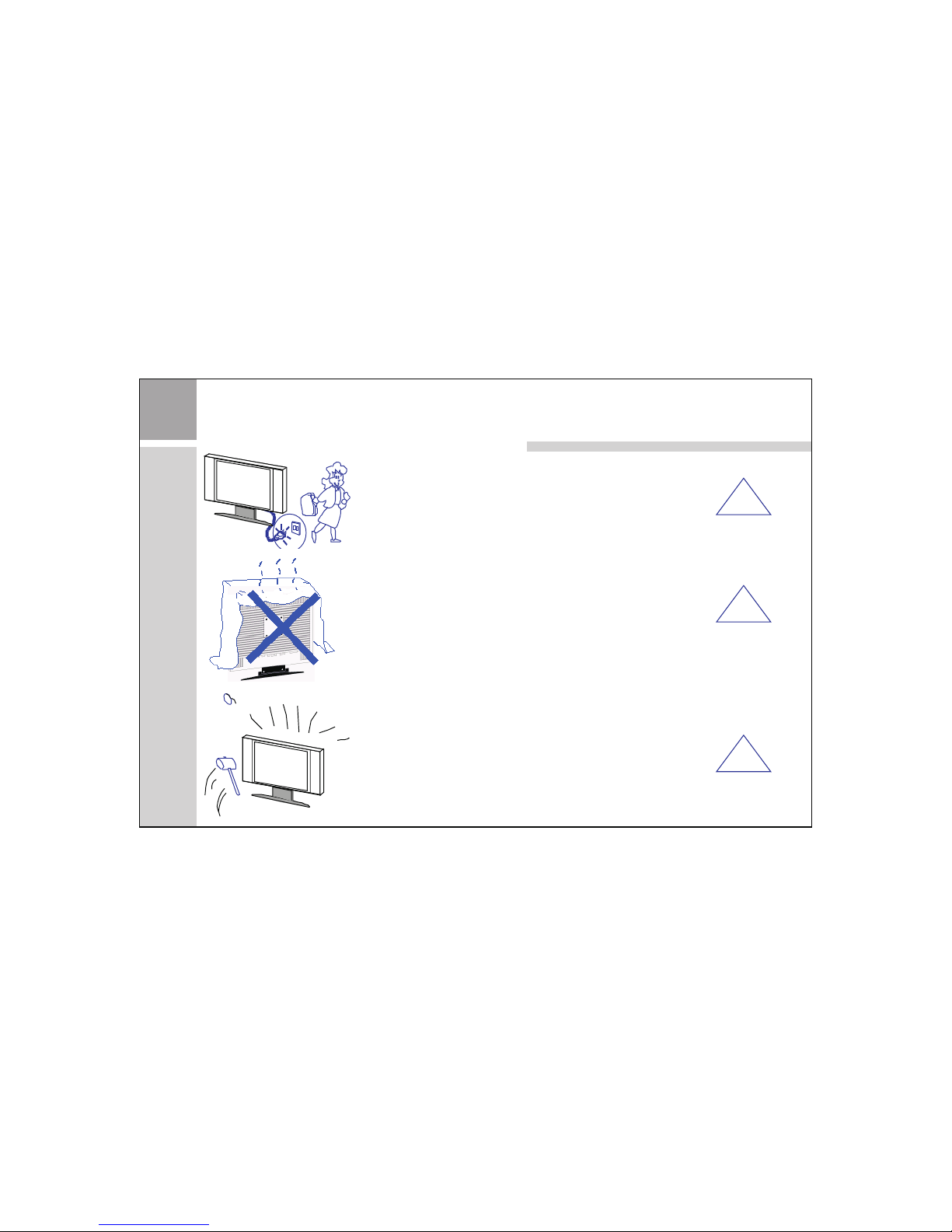
When th e produ ct is not u sed for a n extended p eriod o f time, i t is
advis able to d iscon nect th e AC pow er cord f rom the AC o utlet .
Caution
Avoi d expos ing the m ain uni t to dire ct sunligh t and oth er sour ce
of the he at. Do no t stand t he tele vision rec eiver d irect ly on oth er
produ ct whic h give off hea t. E. g. vi deo cas sette p layers, au dio
ampli fiers . Do not bl ock the v entilati on hole s in the ba ck cove r.
Ventilatio n is esse ntial t o preve nt fail ure of el ectri cal com ponent.
Do not sq uash po wer sup ply cor d under the ma in unit .
Caution
The LCD p anel us ed in thi s produ ct is made of gl ass. Th erefore, i t
can bre ak when t he prod uct is dr opped or app lied wi th impa ct. Be
caref ul not to b e injur ed by bro ken glass pi eces in c ase the L CD
panel b reaks .
4
!
!
!
Page 7
Main unit descriptions
5
8.Power Indicator
9. Remote Sensor
1
2
3
4
5
6
7
9
8
55THLCHD3
1.Power button
2.Volume up button(VOL+)
3.Volume down button(VOL-)
4.Program up button(PR+)
5.Program down button(PR-)
6.Menu button
7.INPUT button
Control location
Page 8
6
Main unit descriptions
8
9
65THLCHD2
1
2
3
4
5
6
7
8.Power Indicator
9. Remote Sensor
1.Power button
2.Volume up button(VOL+)
3.Volume down button(VOL-)
4.Program up button(PR+)
5.Program down button(PR-)
6.Menu button
7.INPUT button
Control location
Page 9
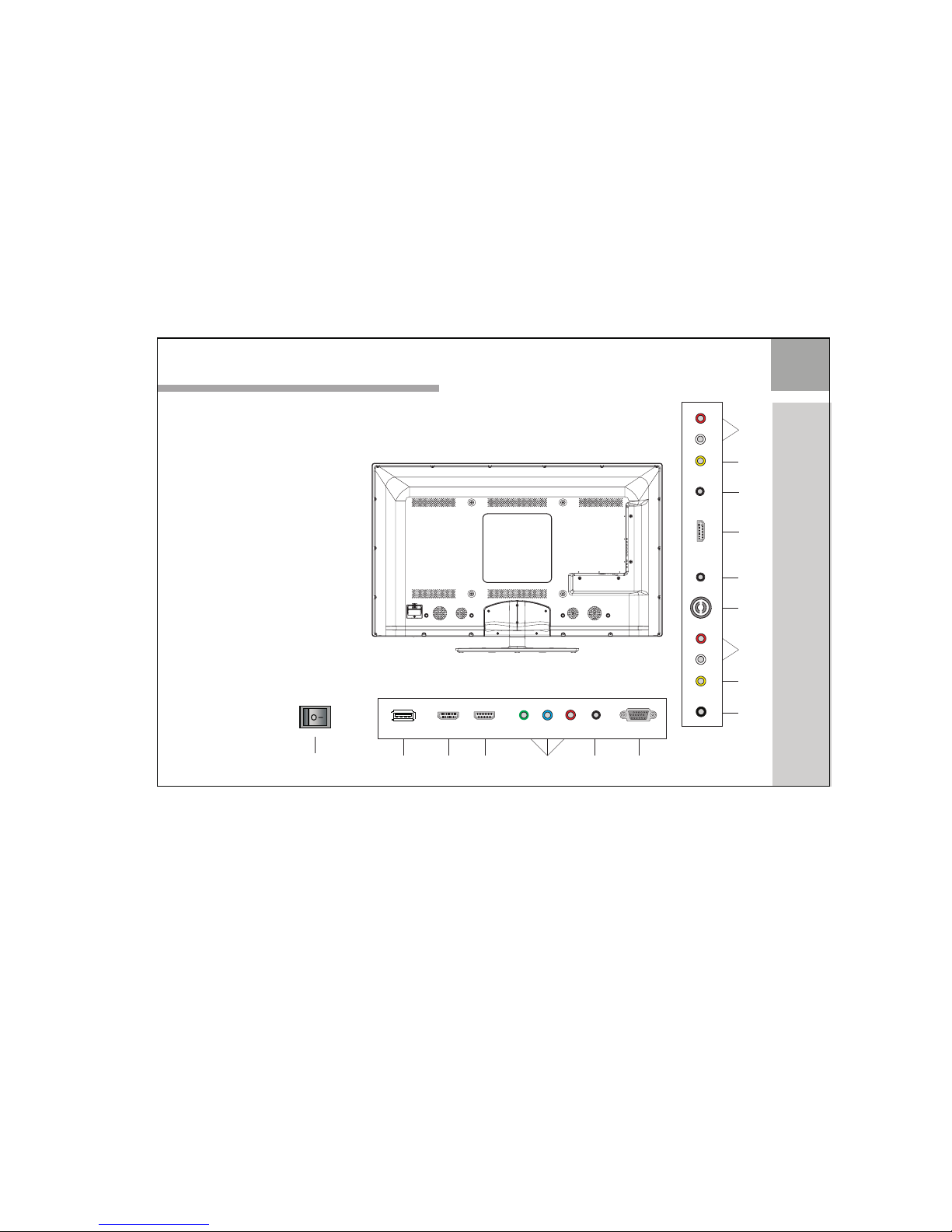
Main unit descriptions
7
RF
20
18
YPbPr 1
17
PC
HDMI1
13
14
12
15
16
USB
EARPHONE
PC
AUDIO IN
11
AV IN
21
12.HDMI1 input socket
13.HDMI2 input socket
14.YPBPR2 input socket
16.PC input socket
19.AUDIO L/R input socket
18.AV intput socket
11.USB input socket
15. input socketPC AUDIO
17.YPBPR1 input socket
20.RF input socket
21. socketCOAXIAL output
HDMI2
COAXIAL
HDMI3
L IN
R IN
19
22
23
AV
L
R
OUT
OUT
OUT
23.Headphone output socket
24
25
22.HDMI3 input socket
24.AV socket output
25.AUDIO L/R output socket
55THLCHD3
10
10.AC power switch
Y2
Pb2
Pr2
Page 10
8
Main unit descriptions
RF
21
19
YPbPr 1
18
PC
HDMI1
14
15
13
16
17
USB
EARPHONE
PC
AUDIO IN
12
AV IN
22
13.HDMI1 input socket
14.HDMI2 input socket
15.YPBPR2 input socket
17.PC input socket
20.AUDIO L/R input socket
19.AV intput socket
12.USB input socket
16. input socketPC AUDIO
18.YPBPR1 input socket
21.RF input socket
22. socketCOAXIAL output
HDMI2
COAXIAL
HDMI3
L IN
R IN
20
23
24
AV
L
R
OUT
OUT
OUT
24.Headphone output socket
25
26
23.HDMI3 input socket
25.AV socket output
26.AUDIO L/R output socket
65THLCHD2
11
10
10.AC power switch
11.AC power input socket
Y2
Pb2
Pr2
Page 11
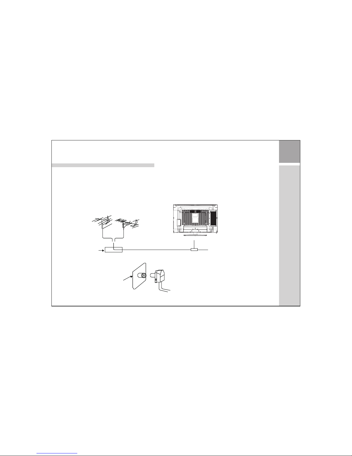
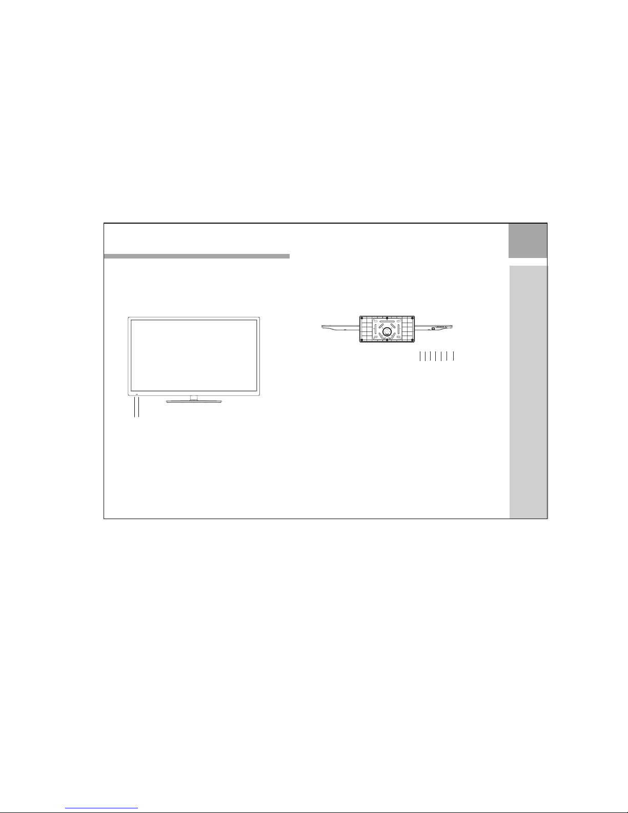
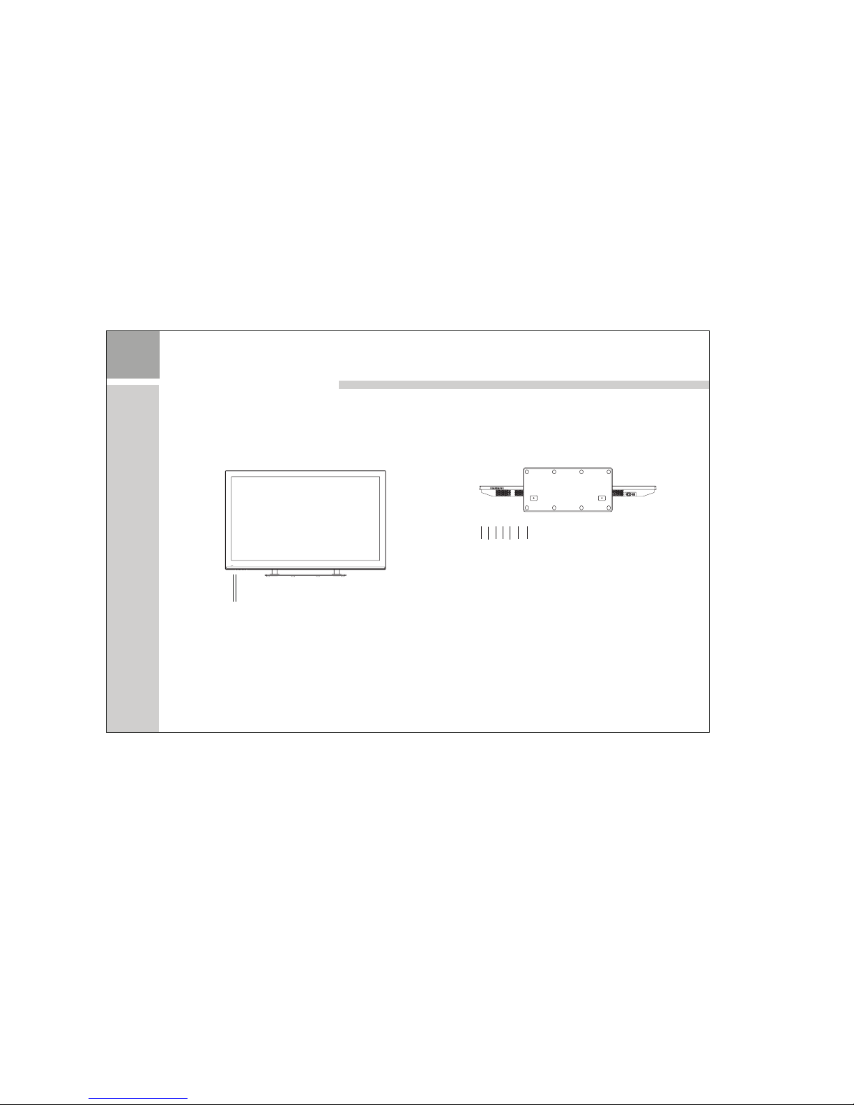
Conne ct ante nna or video f acili ty
1.U s e 7 5Ω coa x ial ca b le pl u g o r 300 - 7 5Ω
imp e d anc e c onve r ter t o p l ug in a n t enn a
inp u t t erm i nal on t h e rea r o f t he ca b i net .
2.C o n nec t t he vid e o fac i l ity t o t h e aud i o ,
vid e o i n jac k o n the re a r of th e c a bin e t .
75 W Co-axi s cable
VHF ant enna
Mix er
UHF a nte nna
Inp ut term inal of a ntenn a
Co-axi s anten na plug
75 W Co-a xis ca ble
Ant enna in j ack
Television Inst allation
9
Page 12

The rem ote con trol us es two 1. 5V AAA batte ries. F or batt ery
insta llati on and re place ment are as fo llowi ng:
1. Turn th e remot e contr ol unit upsi de down . Press d own the g rip
of batt ery com partm ent and s lide the col or in the d irect ion of th e
arrow.
2. Inst all two n ew batt eries , make sure th at batt ery pol arity
match es with t he “ + ”,“ - ”marks i nside t he batt ery. Or
not it co uld dam age the u nit.
3. Clos e the bat tery co mpart ment cover s.
Television Inst allation
10
Page 13

The loc ation a nd func tion of k eys in the R/C a re as the f ollow ing pic ture :
Remot e control pi cture only f or re ference.
The acc urate r emote c ontro l image whil e
your re ceivi ng the re al samp le in hand.
The basic view of Remote Control board
11
/
PMODE
YC53-232A
INPUT
USB
Page 14

12
1 POWER
2 INPUT
3
PMODE
4
SMODE
SLEEP
MUTE
Operation and Function Description of Keys on Remote Control
Turn on and off,carry out the function of standby and turn-on.
By pressing this key, you will see the select menu of input source and you could select the source
which you want quickly, press [OK] key to enter this signal source changes as following:source.
DTV→ATV→YPBPR1→YPBPR2→PC→HDMI1→HDMI2→HDMI3→AV→USB
By pressing this key, the picture mode will change as follows:
Standard→Mild→ →Dynamic→User Standard
By pressing this key, the sound mode will change as follows:
Standard Music Movie User Standard→ → →Sports→ →
5
By pressing [SLEEP] key, the auto turn-off time will change as follows:
Off→10 →20 →30 →60 →90 →120 →180 →240 →min min min min min min min min Off
6
Press this key, sound output will be muted.
Press this key again, the sound volume will return.
7 CALL
Press display to the source and channel information.
Page 15

13
8
9
10
11
12
13
Operation and Function Description of Keys on Remote Control
MENU
EXIT
-/--
ZOOM
Switch the size of the picture in the sequence as following:
Panorama→ 4:3→ 16:9→ Zoom1→ Zoom2→ Panorama
Directly press the number keys to switch to the relevant program.
[0]~[9]
Press this key to jump back to the previous program.
Numeric digits select
- 1 digit mode
- - 2 digit mode
- - - 3 digit mode
Press this key to enter main menu.In the menu, press this key to exit current menu.
Press this key to exit current menu.
By pressing this key, source will switch to USB, directly.
14
USB
15
I/II
In TV source mode, press this key to change Sound processing type of current program.
Page 16

14
16 VOL +/-
19
Call out Favorite List menu.In this menu you can choose preferred TV program very quickly.
TEXT
SIZE
17 CH +/-
FAV
Press this key to enter or exit TELETEXT mode.
CANCEL
Press this key to execute TELETEXT’s CANCEL function.
Press this key to change the display size of TELETEXT characters.
MIX
In teletext mode,press this key to enter or quit the mixing display mode of teletext content.
Operation and Function Description of Keys on Remote Control
Change channel up/down.
When MUTE is off, press [VOL+]/ [VOL-] keys to increase/decrease sound volume.
OK
18
[OK] key is as a confirmable key in the menu operation. The others [ ] /[ ]/[ ]/[ ] are direction keys.
20
21
22
23
24
HOLD
Press this key to keep current displayed TELETEXT page until this function is turn off by pressed this key again.
Page 17

15
26
27
28
29
Press this key to enter RECORD MENU in DTV input source.
31
25
INDEX
RED/ GREEN/YELLOW/BLUE
REVEAL
Press this key to display the revealed content in current TELETEXT page.
SUBCODE
Press this key to execute TE
LETEXT’s SUBCODE function.
SUBTITLE
Press this key to execute TE
LETEXT’s SUBTITLE function.
Press this key Go back directly to TELETEXT’s index page.
Press this key to execute TELETEXT’s RED/GREEN/YELLOW/BLUE function.
It also is a compound keys, can be used in other menu operation.
Operation and Function Description of Keys on Remote Control
EPG
Press EPG key to display the (Digital TV Time table) mode.Press again to exit.
TV/RADIO
30
While watching TV program,press TV/RADIO key to switch between TV and radio modes if available.
32
33
Press this key to play the program.
(REC)
II
34
During playing, Press this key to pause the playing,press it again to continue play.
Page 18

16
35
During playing, Press this key to stop the playing.
By pressing this key , the scan forward speed will change as follows:
Play →FF2X →FF4X → FF8X → FF16X → Play
By pressing this key , the scan backward speed will change as follows:
Play →FB →2X →FB4X → FB8X → FB16X Play
36
37
38
Press this key to select previous page or chapter or picture.
39
Press this key to select next page or chapter or picture.
CH.LIST
40
TIMESHIFT
41
Press TIMESHIFT key to watch the DTV programme by timeshift.
Operation and Function Description of Keys on Remote Control
Press this key to Call out or shut down CHANNEL List menu.
DTV-LAN
42
Press this key to display the audio languages menu.
Page 19

17
Operation and Function Description of Menu
First-time installation
Connect the power cord and antenna to your television; then
turn on the TV. The first time you use your TV,the Installation
Guide menu will appear on the screen as right.
Operate as follows:
1.In the Installation Guide menu, it shows the "OSD Language",
“Country",and "tune type" optional.
2.You can select each available option as you desire.It is
recommended to select "English", "Australia" & "DTV". "ATV"
= Analogue TV which is no longer common.
3. Press OK key to start the scanning.
4.During channel tuning,press MENU key you can skip ATV tuning or DTV
tuning.Press Exit key,you can Exit ATV tuning or DTV tuning.
5.The Installation Guide menu will " Complete " after the scanning is finished.
Press the exit key to exit.
Note:
1. Installation Guide is displayed for the TV mode only when the TV is turned on for the first time.
2. If you would like to scan for stations again,select " Auto scan " in the Channel menu.
Mov e
OK
EXIT
Sel ect
Qui t
Eng lish
OSD L angua ge
Cou ntry
Tune Ty pe
Aus trali a
ATV + DT V
Insta ll ation G uide
Pleas e set t he fo llowi ng op tio ns,th en
Pre ss OK but ton to be gin auto tun ing .
Chann el Tunin g
TV : 3 Pr ogram me(s)
DTV : 0 P rogra mme(s )
Rad io : 0 Prog ramme (s)
MENU
Skip
EXIT
Quit
25 % 47 1.25 MH Z (TV)
- - - - - - - - - - -
Page 20

18
Operation and Function Description of Menu
CHANNEL MENU
Press[MENU] key and then press [ ]/[ ] keys to select
[CHANNEL] menu, press[OK] key to enter [CHANNEL] menu.
AUTO SCAN
Press [ ]/[ ] keys to select Auto Scan, then press
[OK]/[ ] keys to enter sub-menu. select country and tune type.
Press [OK] key to start the Auto scan function.
DTV MANUAL TUNING
Press [ ]/[ ] keys to select DTV MANUAL TUNING, then press [OK] key to enter sub-menu.
Press [ ]/[ ] keys to change channel number,
Press [OK] key to start the DTV manual tuning.
ATV MANUAL TUNING
Press [ ]/[ ] keys to select ATV MANUAL TUNING, then press [OK] key to enter sub-menu.
* Press [ ]/[ ] keys to select STORAGE TO option, then press [ ]/[ ] keys to adjust the
program number.
* Press [ ]/[ ] keys to select SYSTEM, then press [ ]/[ ] keys to select BG/DK/I or L.
* Press [ ]/[ ] keys to select CURRENT CH, then press [ ]/[ ] keys to select the
channel to be adjusted.
* Press [ ]/[ ] keys to select SEARCH, then press [ ]/[ ] keys to start the search.
* Press [ ]/[ ] keys to select FINE-TUNE, then press [ ]/[ ] keys to do the fine tune.
Sinna l Infor matio n
DTV Ma nual Tuni ng
ATV Manu al Tunin g
Progr amme E dit
CHA NNEL
Auto Sc an
Reco rd Star t
Signa l Infor matio n
Page 21

19
Operation and Function Description of Menu
Programme Edit
Press [ ]/[ ] keys to select Programme Edit, then press [OK] key to enter sub-menu.
* key to rename highlighted program. GREEN: Press [GREEN]
* key to move highlighted program. YELLOW: Press [YELLOW]
* key to skip highlighted program. BULE: Press [BULE]
* key to delete highlighted program. RED: Press [RED]
* key to add/remove favorite program. FAV: Press [FAV]
SIGNAL INFORMATION(only for DTV)
The function will shows signal information: Channel, Network, Modulation, Quality and Strength.
The other functions are shown in page 28 to page 31.
PICTURE MENU
Press[MENU] key and then press [ ]/[ ] keys to select
[PICTURE] menu, press[OK] key to enter [PICTURE] menu.
Press [ ]/[ ] keys to select PICTURE MODE , then press
PICTURE MODE
[OK] key to enter Picture Mode menu.
Press [ ]/[ ] keys to change Picture Mode as follows:
Standard→Mild→ →Dynamic→User Standard
When Picture Mode is selected to User, you can adjust the value of contrast, brightness,Color,
sharpness and Tint (only for NTSC signal) by pressing [ ]/[ ]/[ ]/[ ] keys.
PIC TURE
Contr ast 50
Brigh tness 5 0
Color 5 0
Pictu re Mode S tanda rd
Shar pness 50
Tint 50
Page 22

20
Operation and Function Description of Menu
COLOR TEMPERATURE
Press [ ]/[ ] keys to select COLOR TEMPERATURE , then press [OK] key to enter Color Temperature.
Press [ ]/[ ] keys to change Color Temperature as follows: User ↔ Cool ↔ Medium ↔ Warm ↔User
When is selected to User, you Color Temperature can adjust the value of Red, Green and Blue,
by pressing [ ]/[ ]/[ ]/[ ] keys.
ASPECT RATIO
Press [ ]/[ ] keys to select Aspect Ratio, then press [OK] key to enter Aspect Ratio menu.
Press [ ]/[ ] keys to change Aspect Ratio as follows:
Panorama→ 4:3→ 16:9→ Zoom1→ Zoom2→ Panorama
NOISE REDUCTION
Press [ ]/[ ] keys to select Noise Reduction , then press [OK] key to enter Noise Reduction menu.
Press [ ]/[ ] keys to change Noise Reduction as follows: Off↔ Low↔ Middle↔ High↔ Off
SCREEN (only for PC signal)
Press [ ]/[ ] keys to select Screen, then press [OK] key to enter Screen menu.
and vertical of image,and adjust size and phase of image, automatically.
* Press [ ]/[ ] keys to select Auto Adjust,By pressing[OK]key,TV will adjust the position of horizontal
* Press [ ]/[ ] keys to select Horizontal Pos.,Press[ ]/[ ]keys to adjust the horizontal position.
* Press [ ]/[ ] keys to select Vertical Pos.,Press[ ]/[ ]keys to adjust the vertical position.
* Press [ ]/[ ] keys to select Size, Press[ ]/[ ]keys to adjust the sampling frequency.
* Press [ ]/[ ] keys to select Phase, Press[ ]/[ ]keys to adjust the sampling phase.
Page 23

21
Operation and Function Description of Menu
SOU ND
Sound M ode Sta ndard
Trebl e 50
Bass 50
Bala nce 0
Auto Vol ume off
Surr ound Sou nd off
TIM E
Cloc k -- -- -- --
Cloc k -- -- -- --
Clock - - -- -- --
Cloc k -- -- -- --
Cloc k -- -- -- --
Cloc k -- -- -- --
SOUND MENU
Press[MENU] key and then press [ ]/[ ] keys to select
[SOUND] menu, press[OK] key to enter [SOUND] menu.
SOUND MODE
Press [ ]/[ ] keys to select Sound MODE , then press
[OK] key to enter Sound Mode menu.
Press [ ]/[ ] keys to change Sound Mode as follows:
Standard Music Movie User Standard→ → →Sports→ →
When Mode is selected to User, you Sound can adjust the value of Treble and Bass.
by pressing [ ]/[ ]/[ ]/[ ] keys.
BALANCE
Press [ ]/[ ] keys to select Balance , then press [ ]/[ ] keys to adjust the value of balance.
Auto Volume
Press [ ]/[ ] keys to select Auto Volume , then press[OK]key to on/off Auto Volume switch.
SPDIF Mode
Press [ ]/[ ] keys to select SPDIF Mode , then press[OK]key enter sub-menu.
Press [ ]/[ ] keys to select SPDIF Mode as follows: Off PCM Auto → → →Off
SURROUND SOUND
Press [ ]/[ ] keys to select Surround Sound , then press[OK]key to select On or Off.
Page 24

22
Operation and Function Description of Menu
TIM E
Cloc k -- -- -- --
Off Tim e Off
Slee p Timer Of f
Auto Sl eep Off
Time Zo ne Mosc ow GMT+ 3
TIME MENU
Press[MENU] key and then press [ ]/[ ] keys to select
[TIME] menu, press[OK] key to enter [TIME] menu.
On Time O ff
Clock
Press [ ]/[ ] keys to select Clock , then press [OK] key
to enter sub-menu.then adjust Date,Month,Year,Hour and
Minute by pressing [ ]/[ ]/[ ]/[ ] keys.
Off Time
Off Once ↔ ↔
Every Day ↔
Mon.
∼
Fri. ↔
Mon.
∼
Sat. ↔
Sat.
∼
Sun. ↔
Sunday ↔
Off
* the hour of Off Time from 00 to 23.Hour: Press [ ]/[ ] keys to set
* the minute of Off Time from 00 to 59.Minutes: Press [ ]/[ ] keys to set
Press [ ]/[ ] keys to select Off Time, then press [OK] key
to enter sub-menu.
* Repeat: Press [ ]/[ ] keys to set as follows:
On Time
Press [ ]/[ ] keys to select On Time, then press [OK] key to enter sub-menu.
* Repeat: Press [ ]/[ ] keys to set Repeat as follows:
Off Once ↔ ↔
Every Day ↔
Mon.
∼
Fri. ↔
Mon.
∼
Sat. ↔
Sat.
∼
Sun. ↔
Sunday ↔
Off
* the hour of On Time from 00 to 23.Hour: Press [ ]/[ ] keys to set
* the minute of On Time from 00 to 59.Minutes: Press [ ]/[ ] keys to set
* Press [ ]/[ ] keys Source: to select the power-on input source
Page 25

23
Operation and Function Description of Menu
TIM E
* Channel: Press [ ]/[ ] keys to select the power-on channel number while in DTV or ATV
input source.
* Volume: Press [ ]/[ ] keys to select the power-on volume value.
Sleep Timer
Press [ ]/[ ] keys to select Sleep Timer, then press [OK] key to enter sub-menu.
Press [ ]/[ ] keys to change Sleep Timer as follows:
Off→10 →20 →30 →60 →90 →120 →180 →240 →min min min min min min min min Off
Auto Sleep
Press [ ]/[ ] keys to select Auto Sleep, then press [OK] key to select On or Off.
Time Zone
Press [ ]/[ ] keys to select Time Zone, then press [OK] key to enter sub-menu.
Press [ ]/[ ] keys to select your Time Zone. press [OK] key to confirm.
OPTION MENU
Press[MENU] key and then press [ ]/[ ] keys to select
[OPTION] menu, press[OK] key to enter [OPTION] menu.
OPT ION
OSD La nguage E nglis h
Audio L angua ges 1st E nglis h
Subti tle Lan guage s 1st Eng lish
OSD Du ratio n 10s
Audio L angua ges 2nd E nglis h
Subti tle Lan guage s 2nd Eng lish
OSD LANGUAGE
Press [ ]/[ ] keys to select OSD Language, then press [OK]
key to enter sub-menu.
Press [ ]/[ ] keys to select OSD language,press [OK] key to confirm.
Page 26

24
Operation and Function Description of Menu
AUDIO LANGUAGES 1ST
Press [ ]/[ ] keys to select Audio Language 1st, then press [OK] key to enter sub-menu.
Press the [ ]/[ ] keys to select Audio Language 1st, then press [OK] key to confirm.
AUDIO LANGUAGES 2nd
Press [ ]/[ ] keys to select Audio Language 2nd, then press [OK] key to enter sub-menu.
Press the [ ]/[ ] keys to select Audio Language 2nd, then press [OK] key to confirm.
SUBTITLE LANGUAGES 1ST
Press [ ]/[ ] keys to select Subtitle Language 1st, then press [OK] key to enter sub-menu.
Press the [ ]/[ ] keys to select Subtitle Language 1st, then press [OK] key to confirm.
SUBTITLE LANGUAGES 2nd
Press [ ]/[ ] keys to select Subtitle Language 2nd, then press [OK] key to enter sub-menu.
Press the [ ]/[ ] keys to select Subtitle Language 2nd, then press [OK] key to confirm.
OSD DURATION
Press [ ]/[ ] keys to select OSD Duration, then press [OK] key to enter sub-menu.
Press [ ]/[ ] keys to change OSD Duration as follows:
5S→10 →15S →20S →25S→30S→35S→40SS
press [OK] key to confirm.
MEMC
Press [ ]/[ ] keys to select MEMC, then press [OK] key to enter sub-menu.
Press [ ]/[ ] keys to change MEMC as follows:
Off→Demo→High →Middle →Low
press [OK] key to confirm.
Page 27

25
Operation and Function Description of Menu
TIM E
LOCK MENU
Press[MENU] key and then press [ ]/[ ] keys to select
[LOCK] menu, press[OK] key to enter [LOCK] menu.
RESTORE FACTORY DEFAULT
Press [ ]/[ ] keys to select Restore Factory Default, then press [OK] key to enter sub-menu.
Press the [ ]/[ ] keys to select Yes or No. press [OK] key to confirm.
LOC K
Lock C hannel O ff
Set Pa sswor d
Bloc k Progr am
Pare ntal Gui dance O ff
if you are first time to use this menu,you can input 4-digit
number 0000, then TV will transfer Lock Menu automatically.
LOCK CHANNEL
Press [ ]/[ ] keys to select Lock Channel,
Press [OK]key to select On/Off. when ON is selected,the Block Program can be set.
SET PASSWORD
Press [ ]/[ ] keys to select Set Password, press [OK] key to enter sub-menu.
Press number key 0~9 to input the old password.
Press number keys to input the new password.
Press number keys again to confirm the new password.
"
"
BLOCK PROGRAM
Press [ ]/[ ] keys to select Block Program, press [OK] key to enter Block Program menu.
Press the [ ]/[ ] keys to select the specified program to be locked.
Press the [GREEN] key to lock/unlock the program.
Page 28

26
Operation and Function Description of Menu
PARENTAL GUIDANCE
Press [ ]/[ ] keys to select Parental Guidance, press [OK] key to enter sub-menu.
Press the [ ]/[ ] keys to select Parental Guidance, then press [OK] key to confirm.
MEDIA OPERATION
Note Before MEDIA operation plug a USB device into the USB socket of TV set,
then press [INPUT] Media menu as below.key and select input source USB to enter
PHO TO
Disk C:
or Text ,then press [OK] key to enter following menu.
Press [ ]/[ ] keys to select PHOTO or MUSIC or MOVIE
Retu rn
Up Fol der
Retu rn
Up Fold er
3D.mp 3
1KHZ. mp3
.mp3
OK
Select Return to go back to MEDIA main menu.
(Example for Music)
Delet e Curre nt File
Add/R emove a ll
Add/R emove t o playl ist
Album : 2009
Title :
Bit Rat e: 192K
Artis t:
Sampl ing: 44 K
Year: 20 10
Size: 6 743 KBy tes
1 / 2
Page 29

27
Operation and Function Description of Menu
Use [ ]/[ ]/[ ]/[ ] keys to navigate through menu. media file is circled with.
Use [ok] key to enter media file into the play list with a token.
Use [RED] key to delete current file.
Use [GREEN] key to Add/Remove all files.
Keys like [ ](PLAY), [ ](PAUSE), [ ](STOP),[ ](PREVIOUS), [ ](NEXT),
[ ](F.B.) and [ ](F.F.)
After all media file has been added into play list, Press [ ](play) key to play all media file.
OSD display is as following:
Pla y
Repea tALL
Goto Tim e
Remov e
Remov e all fro m playl ist
1 /1
00:00 :05 / 00: 05:07
3D.m p3
1KHZ .mp3
Scree n Saver
3D.m p3
Album : 2009
Title :
Artis t:
Bit Rat e: 192K S ampli ng 44K
Year 201 0 Size: 6 743KB ytes
(Example for Music)
Use [ ]/[ ] key to select different icon, press [ OK ] key to confirm select and execute associated function.
The PHOTO/MOVIE/TEXT replay is same as MUSIC.
Page 30

28
Operation and Function Description of Menu
RECORD START (inserting USB equip).
Press[MENU] key and then press [ ]/[ ] keys to select [CHANNEL] menu,
then press [ ] key to select RECORD START, Press [OK] key to start record.
*You can press key on the remote (REC) control to start record
or [ ] key to end record.
Delet e
Selec t
Call
Index
OK
CALL
INDEX
Reco rded Li st
Progr amme
SEVE N MORNI NG NEWS
RECORD LIST (inserting USB equip).
Press [OK] key to enter RECORD LIST menu.
Press [RED] key to delete the programme in List.
Press [CALL] key to display information you select programme.
Press [OK] key to play programme you select.
Press Index key to list the programme in the fllowing sequence:
Channel Time Programme → → →Channel
Press[MENU] key and then press [ ]/[ ] keys to select
[CHANNEL] menu,
then press [ ] key to select RECORD LIST.
RECORD TO USB FUNCTION (PVR MODE)
Only oprates under DTV mode. Not used for other input mode.
Page 31

29
Operation and Function Description of Menu
Artis t:
Bit Rat e: 192K S ampli ng 44K
RECORD MODE (inserting USB equip).
Press[MENU] key and then press [ ]/[ ] keys to select [CHANNEL] menu,
then press [ ] key to select RECORD MODE.
Press [OK] key to enter RECORD MODE menu.
Press [ ]/[ ] keys to select channel and press [ ]/[ ] keys to change channel number.
Auto Once Every Day Weekly ↔ ↔ ↔ ↔ Auto
Press [ ]/[ ] keys to select Mode and press [ ]/[ ] keys to select Mode:
Press [ ]/[ ] keys to select Start Time option (Minute/Hour/Date/Month) and press
[ ]/[ ] keys to adjust value of each option.
Press [ ]/[ ] keys to select End Time option (Minute/Hour/Date/Month) and press
[ ]/[ ] keys to adjust value of each option.
SCHEDULE LIST (inserting USB equip).
Press[MENU] key and then press [ ]/[ ] keys to select [CHANNEL] menu,
then press [ ] key to select SCHEDULE LIST .
Press [OK] key to enter menu.SCHEDULE LIST
Press [ ]/[ ] keys to select plans.
Press [RED] key to delete plans.
PVR FILE SYSTEM (PVR MODE)
Press[MENU] key and then press [ ]/[ ] keys to select [CHANNEL] menu,
then press [ ] key to select PVR FILE SYSTEM.
Press [OK] key to enter menu.PVR FILE SYSTEM
Page 32

30
Operation and Function Description of Menu
* SELECT DISK
Choose the disk to store whatever content need record as follows, default as C:
Press [ ]/[ ] keys to select SELECT DISK.
Press [OK] key to enter sub-menu.SELECT DISK
* CHECK PVR FILE SYSTEM
Press [ ]/[ ] keys to select Check PVR File System.
Press [OK] key to enter Check PVR File System.
When no inserting USB or inspection failed, it shows FAIL.
When inserting USB but didn t Pass Mstar Format, enter Format menu.
,
When inserting USB but inspecting unnormal no partition, it shows No Partition Found.
If inspection normal, it shows SUCCESS.
* FORMAT
Press [ ]/[ ] keys to select FORMAT.
Press [OK] key to enter Format sub-menu.
Press [ ]/[ ] keys to select PVR File System Type:
FAT32 or Hi Speed FS. (In select PVR File System Size).Hi Speed FS mode, you can
In FAT32 mode: After format, return to previous menu.
Press [OK] key to enter format disk.
In Hi Speed FS mode: After format, create PVR file system and enter Time Shift size menu to
select time shift disk size. Press [OK] key to finish.
Page 33

31
Operation and Function Description of Menu
TIMESHIFT(only oprates under DTV mode)
*We strongly command that the capacity of the USB Device which to be used must be 2G or over.
1.Before use this function,make sure turn the TV on and under the DTV mode.
2.Press [ ](PLAY), the screen will appear index bar as fellow:
3."Shife time/max shift time" in the index Bar shows the max time can be reviewed for this function.
4.Press [ ](PLAY) or [OK] keys to start watching continuely again.
5.Press "Stop" key to back to normal DTV condition.
,
6.Can using remote contral s [ ]/[ ] keys to select the Fast forward and backwards Duing
"Time shifting" period and select the particular section that you need to watch.
Play
FB
FF
Prev.
Next
Pause
Stop
11:56
SHIF T TIME/ MAX SHI FT TIME : [ 00:00 :15/0 0:01: 17 ]
A-B
Page 34

32
Before arr angin g for servic e, firs tly kno w the sta tus and t hen che ck simp ly as fol lows:
Pro blems
Check
No pict ure or so und.
Pictu re is OK, no soun d.
Remot e contr ol does n't wor k.
No TV s ignal.
No exte rnal vi deo sig nal.
Pictu re lack s colou r or pict ure
too dar k.
Check i f the pow er supp ly is plu gged in.
Check i f the pow er swit ch is in "o n" posi tion.
Check i f the vol ume con trol is s et to the mini mum or mu te posi tion.
Check i f the pow er swit ch is in "o n" posi tion.
Check i f the bat terie s are out o f use or not con necte d well.
Make su re that t here is n o stron g light stri king th e senso r windo w of
remot e contr ol unit .
Check t here ar e no obst acles b etween the s ensor w indow a nd
remot e contr ol unit .
Check i f the sou rce but ton is no t set to TV st atus.
Check i f the ant enna is w ell con nected.
Check i f you ins talle d the TV cor rectl y.
Check i f you ins talle d the TV cor rectl y.
Check i f the sou rce but ton is se t to AV pos ition .
Check c olour, b right ness an d contr ast con trols a re corr ectly
adjus ted.
Troubleshooting
Page 35

33
Pro blems Check
All cha nnels l ose col our
inter mitte ntly.
Poor re crpti on,lo ss of cou lur
with ce rtain c hanne ls.
Diago nal str ipes ap pear on
pictu re.
Pictu re has "s now".
Ghost i mages a ppear.
Check i f the ant enna is b roken .
Check i f the ant enna is d iscon nected.
Check i f the ant enna is d amage d.
Check i f chann els are c orrec tly tuned( see "Fi ne tuni ng").
The rec eiver m ay be affect ed by int erfer nece( e.g. From ne arby
radio b roadc astin g trans mitter of fo rm anot her TV recei ver).
Check i f the ant enna is b roken .
Check i f the ant enna is d isaco nnected.
Check i f the ant enna is d amage d.
Check i f the anr enna di eecti on has been ch anged b y a storm o r
stron g wind, ect.( becau se ghos t images are c aused b y the arr ival at
the ant enna of b oth the s ignal w hich has tra celed d irect ly from t he
trans mitte r and the s ignal w hich has bee n refle cted fr om a hill o r a
large buil ding. The dir ectio n of the an tenna s houle be cho sen for
minim ized gh ostin g).
Troubleshooting
 Loading...