

Page 1

AVT
MANUAL
2MP Temperature Measurement &
Face Recognition Terminal
BT800A-DU
Page 2

Notes on Safety
This product is intended to be supplied by a Listed Power
'Limited Power Source', 'LPS' on unit, output rated minimum 12V/1 A, no more
than 2000m altitude of operation and Tma=60 Deg.C.
Do not attempt to disassemble the camera; in order to prevent electric
shock, do not remove screws or covers.
There are no user-serviceable parts inside. Please contact the nearest
service center as soon as possible if there is any failure.
Avoid from incorrect operation, shock vibration, heavy pressing which
can cause damage to product.
Do not use corrosive detergent to clean main body of the camera. If
necessary, please use soft dry cloth to wipe dirt; for hard contamination,
use neutral detergent. Any cleanser for high grade furniture is applicable.
Avoid aiming the camera directly towards extremely bright objects, such as,
sun, as this may damage the image sensor.
Please follow the instructions to install the camera. Do not reverse the
camera, or the reversing image will be received.
Do not operate it in case temperature, humidity and power supply are
beyond the limited stipulations.
Keep away from heat sources such as radiators, heat registers, stove, etc. Do
not expose the product to the direct airflow from an air conditioner. This
manual is for using and managing the product. We may reserve the rights of
amending the typographical errors, inc onsistencies with the latest version,
software upgrades and product improvements, interpretation and
modification. These changes will be unpublished in the latest version without
special notification.
All pictures, charts, images in this manual are only for description and
explanation of our products. The ownerships of trademarks, logos and
other intellectual properties related to Microsoft, Apple and Google belong
to the above-mentioned companies.
This manual is suitable for face recognition network cameras.
Unit, marked with
Page 3

Disclaimer
With regard to the product with internet access, the use of product shall
be wholly at your own risks. Our company shall be irresponsible for
abnormal operation, privacy leakage or other damages resulting from
cyber attack, hacker attack, virus inspection, or other internet security risks;
however, our company will provide timely technical support if necessary.
Surveillance laws vary from country to country. Check all laws in your
local region before using this product for surveillance purposes. We shall
not take the responsibility for any consequences resulting from illegal
operations.
Regulatory Information
FCC Information
1. FCC compliance
The products have be tested and found in compliance with the council
FCC rules and regulations part 15 subpart B. These limits are
designed to prov ide reasonable protection against harmful interference.
This equipment generates uses and can radiate radio frequency energy
and, if not installed and used in accordance with the instruction manual,
may cause harmful interference to radio communication. However, there is
no guarantee that interference will not occur in a particular installation.
The user will be required to correct the interface at his own expen se in
case the harmful interference occurs.
2. FCC conditions:
Operation of this product is subject the following two conditions: (1) this
device may not cause harmful interface, and (2) this device must accept
any interference received, including interference that may cause undesired
operation.
CE Information
The produ
directives. EMC Directive 2014/30/EU
cts have been manufactured to comply with the following
RoHS
The products have designed and manufactured in accordance with
Directive EU RoHS Directive 2011/65/EU and its amendment Directive EU
2015/863 on the restriction of the use of certain hazardous substances in
electrical and electronic equipment.
Page 4

Temperature Measurement & Face Recognition Terminal User Manual
2012/19/EU (WEEE directive): The Directive on waste electrical and
electronic equipment (WEEE Directive). To improve the
environmental management of WEEE, the improvement of
collection, treatment and recycling of electronics at the end of
their life is essential. Therefore, the product marked with this
symbol must be disposed of in a responsible manner.
Directive 94/62/EC: The Directive aims at the management of packaging and
packaging waste and environmental protection. The packaging and packaging
waste of the product in this manual refers to must be disposed of at designated
collection points for proper recycling and environmental protection.
REACH(EC1907/2006): REACH concerns the Registration, Evaluation, Authorization
and Restriction of Chemicals, which aims to ensure a high level of protection of
human health and the environment through better and earlier identification of
the intrinsic properties of chemical substances. The product in this manual refers
to conforms to the rules and regulations of REACH. For more information of
REACH, please refer to DG GROWTH or ECHA websites.
Page 5

Table of Contents
1 Introduction ............................................................................................................................. 1
2 Network Connection
1.1 LAN
1.1.1 Access through IP-Tool
1.1.2 Directly Access through IE
1.2 WAN
3 Temp Measurement & FR Config
3.1 Temperature Measurement Settings
3.2 Face Match Configuration
3.3 Face Database Management
3.4 Mask Detection
4 Live View
4.1 Temperature Measurement & Face Recognition View
4.1.1 Temperature Measurement Requirements
4.1.2 Temperature Measurement & Face Recognition View
4.2 Live View via Web
5 Access Control Settings
5.1 Door Lock Settings
5.2 Wiegand Settings
5.3 Tampering Alarm Settings
6 Other Configurations
6.1 System Settings
6.1.1 Basic Information
6.1.2 Date and Time
6.1.3 Local Config
6.1.4 Storage
6.2 Image Configuration
6.2.1 Display Configuration
6.2.2 Video / Audio Configuration
6.2.3 OSD Configuration
6.2.4 Screen Brightness
6.2.5 White Light Control
6.2.6 Face Exposure
6.3 Alarm Configuration
6.3.1 Exception
6.3.2 SD Card Full
6.3.3 SD Card Error
6.3.4 IP Address Conflict
......................................................................................................................................
....................................................................................................................................
..................................................................................................................................
..........................................................................................................................
.............................................................................................................
........................................................................................
...................................................................................
.......................................................................................
.............................................................................
.............................................................................................
.......................................................................................
.................................................................................................................
............................................
.............................................................
........................................
.............................................................................................................
......................................................................................................
............................................................................................................
.............................................................................................................
..............................................................................................
...........................................................................................................
..................................................................................................................
..........................................................................................................
..............................................................................................................
..................................................................................................................
.......................................................................................................
................................................................................................
...................................................................................
......................................................................................................
.......................................................................................................
....................................................................................................
.............................................................................................................
........................................................................................................
.......................................................................................................................
..................................................................................................................
...............................................................................................................
......................................................................................................
10
11
12
14
14
14
16
17
19
19
20
21
21
21
21
22
23
23
26
26
27
29
29
30
30
30
30
32
32
33
2
2
2
4
5
9
9
Page 6

Temperature Measurement & Face Recognition Terminal User Manual
6.3.5 Cable Disconnection ................................................................................................
6.3.6 Alarm In ......................................................................................................................... 33
6.3.7 Alarm Out
6.4 Network Configuration
6.4.1 TCP/IP
6.4.2 Port
6.4.3 Server Configuration
6.4.4 DDNS
6.4.5 RTSP
6.4.6 UPnP
6.4.7 Emai
6.4.8 FTP
6.4.9 HTTPS
6.4.10 P2P (Optional) ....................................................................................................
6.5 Security Configuration ..........................................................................................
6.5.1 User Configuration .............................................................................................
6.5.2 Online User
6.5.3 Block and Allow Lists
6.5.4 Security Management
6.6 Maintenance Configuration ................................................................................
6.6.1 Backup and Restore..........................................................................................
6.6.2 Reboot
6.6.3 Upgrade
6.6.4 Operation Log
7 Search ...........................................................................................................................
7.1 Image Search
7.2 Video Search
7.2.1 Local Video Search
7.2.2 SD Card Video Search
8 Face Match Result Search
Appendix
Appendix 1 Troubleshooting
Appendix 2 Specifications
..............................................................................................................................
.................................................................................................................... 34
................................................................................................. 35
........................................................................................................................... 35
............................................................................................................................... 37
................................................................................................ 37
............................................................................................................................ 37
............................................................................................................................... 39
......................................................................................................................
l ......................................................................................................................
.........................................................................................................................
...................................................................................................................
..........................................................................................................
........................................................................................
......................................................................................
.................................................................................................................
..............................................................................................................
....................................................................................................
...........................................................................................................
............................................................................................................
........................................................................................
......................................................................................
........................................................................................
.........................................................................................
.............................................................................................
........
........
........
........
........
........
........
........
........
........
........
........
........
........
........
........
........
........
........
........
........
........
........
........
33
40
40
41
41
43
43
43
45
45
46
47
47
47
48
48
49
49
51
51
52
55
56
56
58
Page 7

1 Introduction
This seri
es of product is specially designed and developed for face
recognition and temperature measurement applications, featuring noncontract temperature measurement, high performance and reliability, faster
recognition and higher accuracy rate. Based on deep-learning algorithm,
it combines temperature measurement, identity authorization and access
control.
It can be widely used in the entrances and exits of community, schools, hospitals,
scenic areas, hotels, shopping malls, office buildings, public services and
construction sites for body temperature measurement, identity authorization and
access control.
Main Features
8 inch LCD screen
High-accuracy IR body temperature measurement
Non-contact body temperature measurement
Human-sounding voice prompt
Real-time face mask detection
Face liveness detection technology distinguishing real faces from non-real
face spoof attacks
Highly accurate face recognition using deep learning algorithm
Stand-alone device, ready for networking
1
Page 8
2 Network Connection
Connect IP-Cam via LAN or WAN. Here only take IE browser for example. The
details are as follows:
1.1 LAN
In LAN, there are two ways to access IP-Cam: 1. access through IP-Tool; 2.
directly access through IE browser.
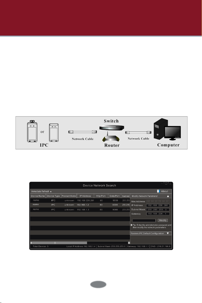
1.1.1 Access through IP-Tool
Network connection:
① Make sure the PC and IP-Cam are connected to the LAN and the IP-Tool is
installed in the PC from the CD.
② Double click the IP-Tool icon on the desktop to run this software as shown
below:
③ Modify the IP address. The default IP address of this camera is 192.168.226.201.
Click the information of the camera listed in the above table to s how the
network information on the right hand. Modify the IP address and gateway of
the camera and make sure its network
2
Page 9
Temperature Measurement & Face Recognition Terminal User Manual
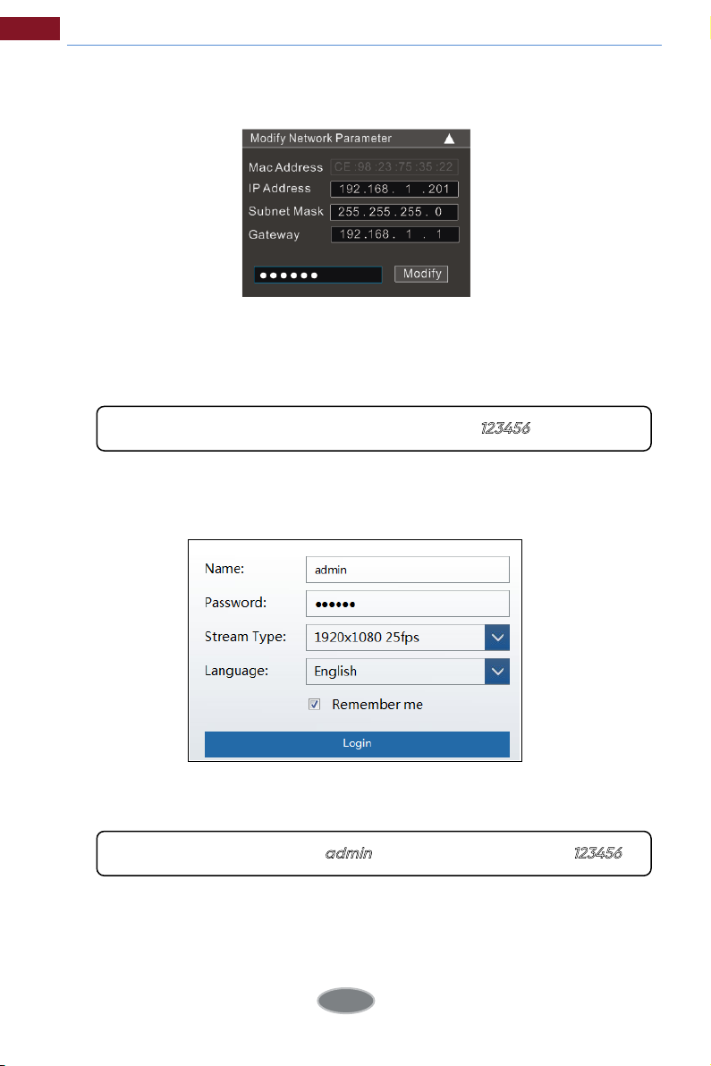
address is in the same local network segment as the computer’s. Please modify
the IP address of your device according to the practical situation.
For example, the IP address o f your computer is 192.168.1.4. So the IP address of
the camera shall be changed to 192.168.1.X. After modification, please enter
the password of the administrator and click the “Modify” button to modify the
setting.
④ Double click the IP address and then the system will pop up the IE browser to
connect IP-CAM. Follow directions to download, install and run the Active X
control.
Enter the username and password in the login window to log in.
The default password of the administrator is “
The default username is “
admin
”; the default password is “
123456
”.
123456
”.
3
Page 10
Temperature Measurement & Face Recognition Terminal User Manual
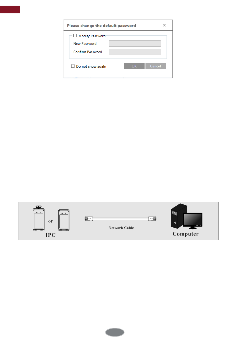
The system will pop up the above -mentioned text box to ask you
to change the default password. It is strongly recommended to change
the default password for account security. If “Do not show again” is checked,
the text box will not appear next time.
1.1.2 Directly Access through IE
The default network settings are as shown below:
IP address: 192.168.226.201
Subnet Mask: 255.255.255.0
Gateway: 192.168.226.1
HTTP: 80
Data port: 9008
Use the above default settings when logging in the camera for the first time.
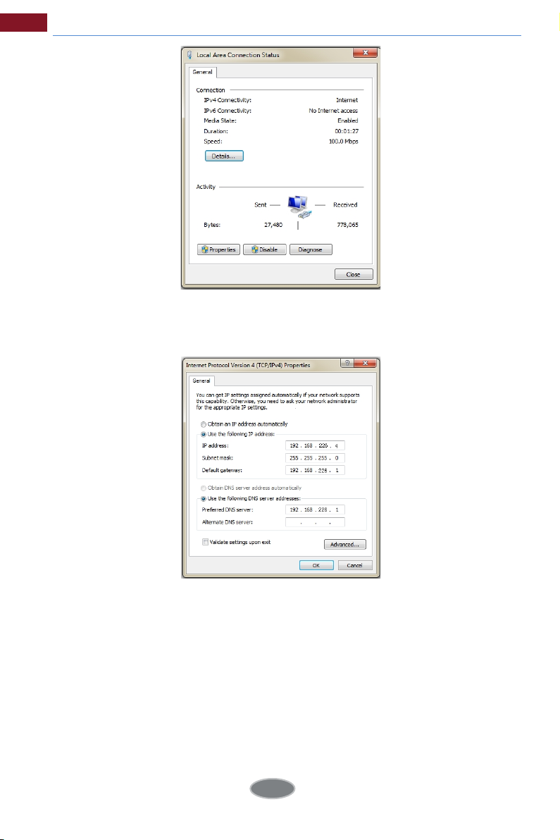
Directly connect the camera to the computer through network cable.
① Manually set the IP address
the same as the default settings of the IP camera. Open the network and share
center. Click “Local Area Connection” to pop up the following window.
of the PC and the network segment should be as
4
Page 11
Temperature Measurement & Face Recognition Terminal User Manual
Select “Properties” and then select internet protocol according to the actual
situation (for example: IPv4). Next, click the “Properties” button to set the
network of the PC.
② Open the IE browser and enter the default address of IP-CAM and confirm.
③ Follow directions to download and install the Active X control.
④ Enter the default username and password in the login window and then enter
to view.
1.2 WAN
Access through the router
or virtual server
5
Page 12
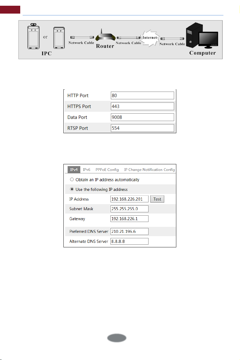
Temperature Measurement & Face Recognition Terminal User Manual
① Make sure the camera is connecte
camera via LAN and go to ConfigNetworkPort menu to set the port number.
② Go to Config NetworkTCP/IP menu to modify the IP address.
d to the local network and then log in the
Port Setup
IP Setup
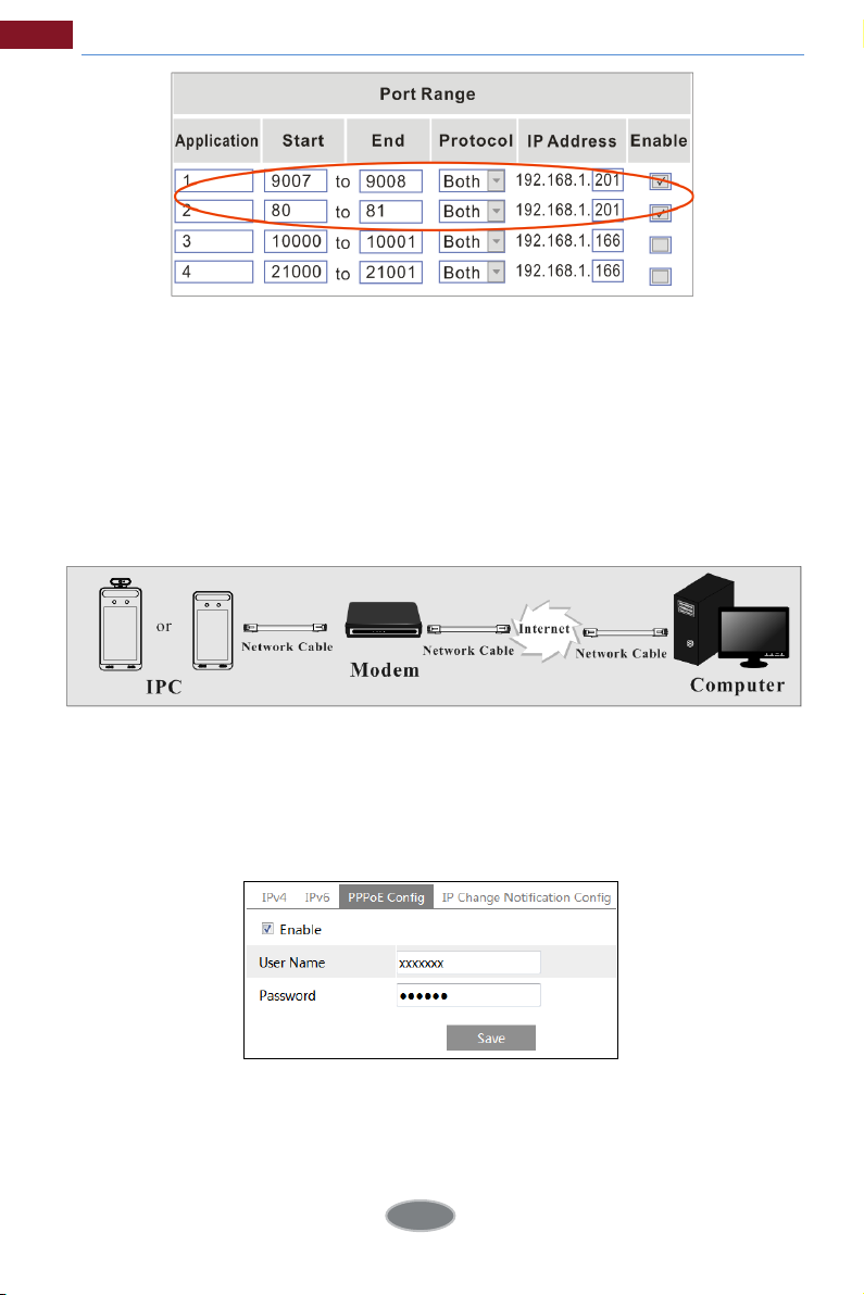
③ Go to the router’s management interface through IE browser to forward the IP
address and port of the camera in the “Virtual Server”.
6
Page 13
Temperature Measurement & Face Recognition Terminal User Manual
Router Setup
④ Open the IE browser and e nter its WAN IP and http port t o access. (for
example, if the http port is changed to 81, please enter “192.198.1.201:81” in the
address bar of web browser to access).
Access through PPPo
Network connection
Access the camera through PPPoE auto dial-up. The setup steps are as follow:
① Go to ConfigNetworkPort menu to set the port number.
② Go to Config NetworkTCP/IPPPPoE Config menu. Enable PPPoE and
then enter the user name and password from your internet service provider.
③ Go to Config NetworkDDNS menu. Before configuring the DDNS, please
apply for a domain name first. Please refer to DDNS configuration for detail
information.
④ Open the IE browser and enter the domain name and http port to access.
E dial-up
7
Page 14
Temperature Measurement & Face Recognition Terminal User Manual
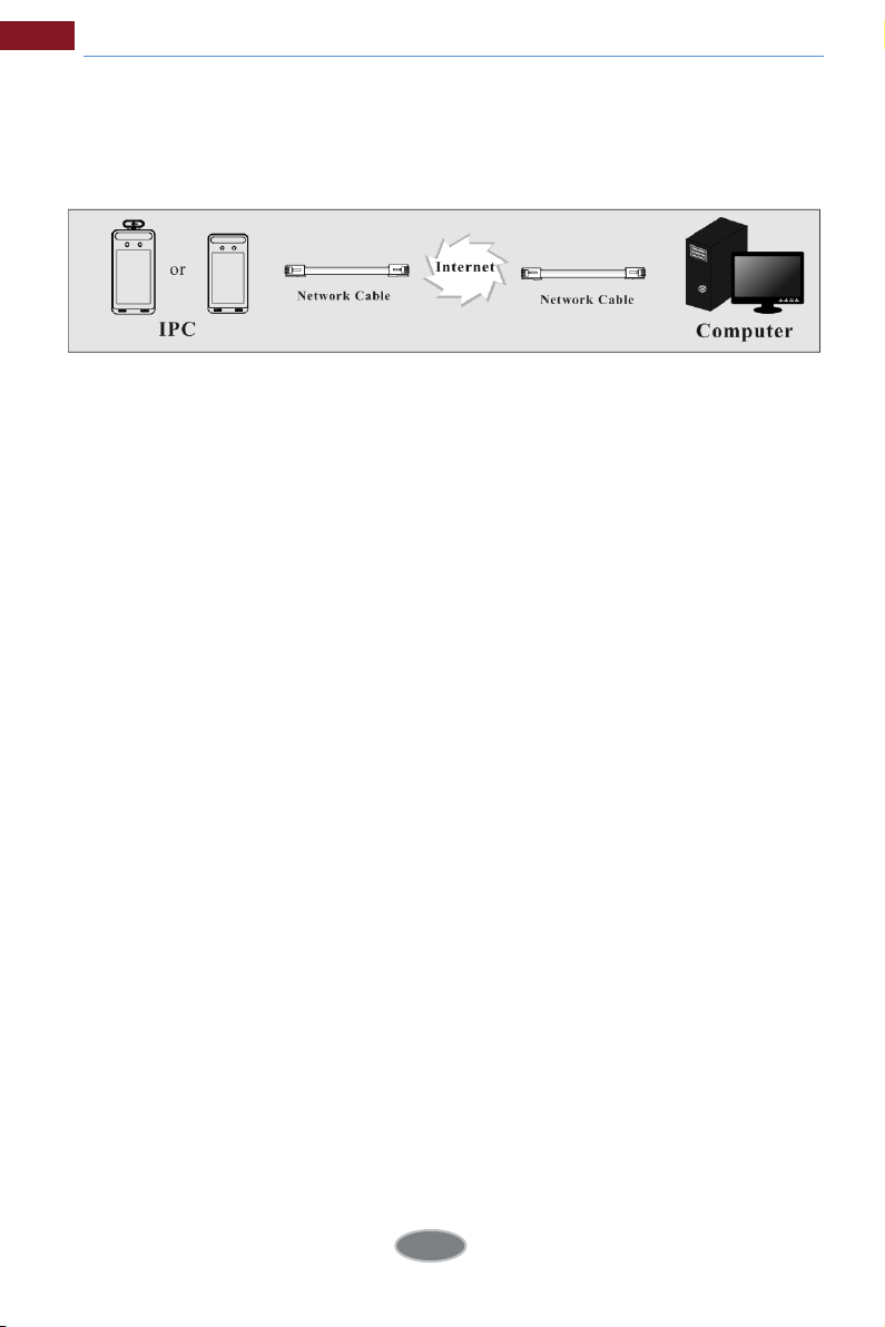
Access through static IP
Network connection
The setup steps are as follow:
① Go to ConfigNetworkPort menu to set the port number.
② Go to Config NetworkTCP/IP menu to set the IP address. Check “Use the
following IP address” and then enter the static IP address and other parameters.
③ Open the IE browser and enter its WAN IP and http port to access.
8
Page 15
3 Temp Measurement & FR Config
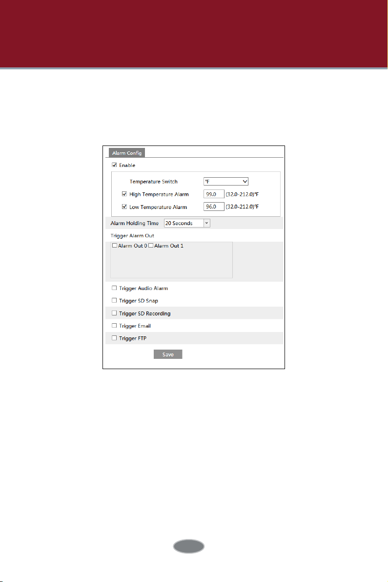
3.1 Temperature Measurement Settings
After the networ
Click ConfigTemperature Measurement to go to the following interface.
1. Enable “Temperature Measurement”, select Celsius or Fahrenheit temperature
as needed and then set the high temperature threshold and the low
temperature threshold. When the body temperature measured is higher or lower
than the set value, it will trigger alarms.
2. Set the alarm holding time.
3. Set the alarm trigger options. Trigger Alarm Out: If enabled, the alarm output device will be triggered when detecting abnormal temperature. Trigger Audio Alarm: If enabled, the system will broadcast the current body temperature on detecting a body. No matter whether the detected body temperature is normal or not, the corresponding voice prompt will be heard. If this item is disabled, the detected temperature will be not broadcasted. Trigger SD Snap: If enabled, the system will capture images on detecting abnormal
k is connected, go to the web client.
9
Page 16
Temperature Measurement & Face Recognition Terminal User Manual
temperature alarm and save the images on an SD card.
Trigger SD Recording: If selected, video will be recorded on an SD card on
detecting abnormal temperature alarm.
Trigger Email: If “Trigger Email” and “Attach Picture” are checked (email address
must be set first in the Email configuration interface), the captured pictures and
triggered event will be sent into those addresses.
Trigger FTP: If “Trigger FTP” is checked, the captured pictures will be sent into FTP
server address. Please refer to FTP configuration chapter for more details.
4. Click “Save” to save the settings.
3.2 Face Match Configuration
The setting steps are as follows.
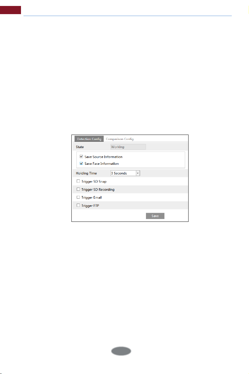
1. Go to ConfigFaceFace Match Config interface.
2. Enable “Save Source Information” or “Save Face Information”.
Save Source Information: if checked, the whole picture will be saved to the SD
card when detecting a face.
Save Face Information: if checked, the captured face picture will be saved to
the SD card when detecting a face.
Note: To save images to the local PC, please enable the local smart snapshot
storage first (Config System Local Config). To save images to the SD card,
please install an SD card first.
3. Set alarm holding time and alarm trigger options.
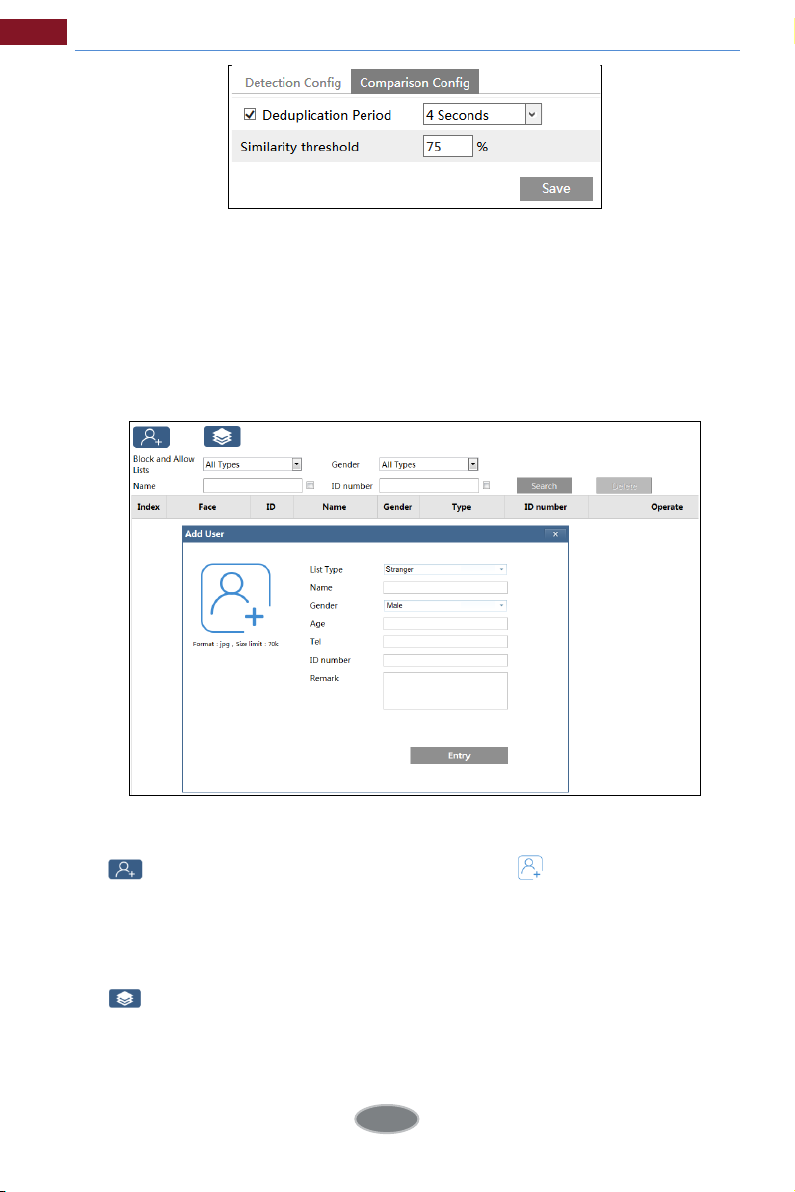
3. Set face comparison options.
10
Page 17
Temperature Measurement & Face Recognition Terminal User Manual
Deduplication Period: In the set period, delete the repeated comparison results.
Similarity threshold: When the similarity of the captured face picture and the
face picture added into the face database exceeds the similarity threshold,
alarms will be triggered.
3.3 Face Database Management
Click “Face Database Management” tab. This will enter the following interface.
There are four ways to add face pictures.
① Adding face pictures one by one
Click to pop up an adding user box. Then click to select a face
picture saved on the local PC. Please select the picture according to the
specified format and size limit. After that, fill out the relevant information of the
face picture and click “Entry” to add.
② Adding multiple face pictures at a time
Click and then add multiple face pictures once according to the prompted
rules.
③ Add face pictures by using face album management tool
④ Add
the captured picture in the live mode (See
the face database
).
11
Add captured face pictures to
Page 18
Temperature Measurement & Face Recognition Terminal User Manual
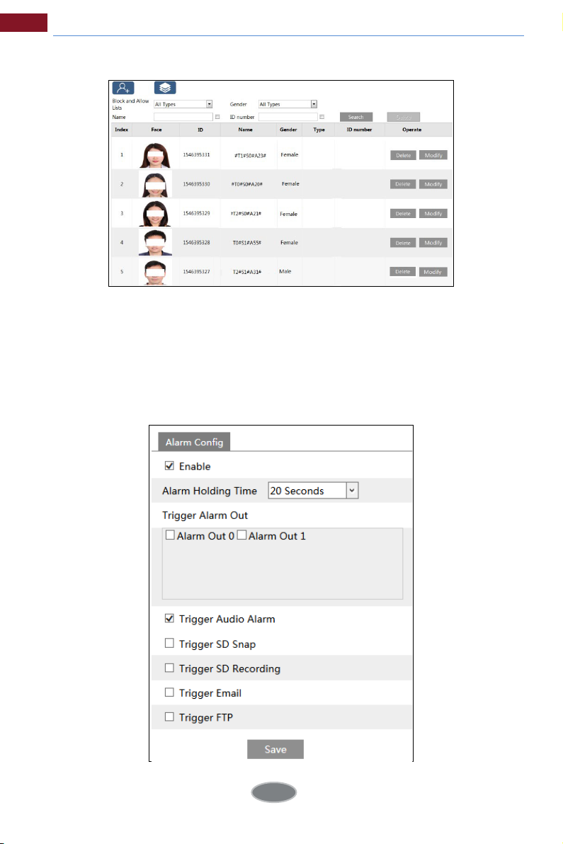
After adding face pictures, you can search them by name, gender, ID number and
so on.
Click “Modify” to change people information and click “Delete” to delete this face
picture.
3.4 Mask Detection
Click ConfigAlarmMask Detection to go to th e following interface.
12
Page 19

Temperature Measurement & Face Recognition Terminal User Manual
① Enable “Mask Detection” as needed.
② Set the alarm holding time.
③ Set the alarm trigger options.
Alarm Out: If enabled, alarm output will be triggered when the detected person
doesn’t wear a mask.
Trigger Audio Alarm: If enabled, the alarm voice will be heard when the detected
person doesn’t wear a mask.
The setup steps of other alarm trigger options are the same as temperature
measurement settings. Please refer to temperature measurement settings chapter
for details.
13
Page 20
4 Live View
4.1 Temperature Measurement & Face Recognition View
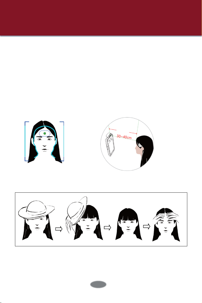
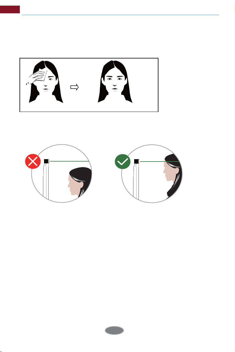
4.1.1 Temperature Measurement Requirements
For accuracy temperature measurement, here are some recommendations.
1. The face image of the detected person shall be within the pre-defined face
detection area.
His/her forehead shall be in the middle of the “Temp zone” (make the green plus
stay in the middle of the “Temp zone”). The detected face shall be 30cm~40cm
away from the temperature measurement sensor.
2. Please remove the hat/cap/helmet/hair covering the forehead for accuracy
temperature
3. The accurate temperature will
person doesn’t aim at the “Temp zone”.
4. If the temperature is very lower than the normal value, please move towards
measurement.
not be gotten if the forehead of the detected
14
Page 21
Temperature Measurement & Face Recognition Terminal User Manual
the temperature measurement sensor (5cm-20cm away from the
temperature sensor) to get the accurate value.
5. Please have a rest after strenuous exercise and then test the temperature. If
e is sweat on the forehead, please wipe it and take a rest and then test
ther
the temperature.
6. The installation height shall fit the height of the detected people. Note that the
temperature measurement module shall not be higher than the height of the
detected people.
Note: If your terminal
closer, raise your wrist and then make your inside wrist point at the
temperature measurement sensor (1~5cm away from the TM sensor).
is a wrist temperature measurement terminal, please come
4.1.2 Temperature Measurement & Face Recognition View
After configuring temperature measurement and face match, the temperature
and face match result can be viewed on the screen.
When detecting a face, the device will display the following interface.
Please measure the body temperature according to the above-mentioned
temperature measurement requirements.
Abnormal temperature: the red block and temperature will be shown.
Normal temperature: the green block and temperature will be shown.
If “Trigger Alarm Audio” is selected, you will hear the alarm voice.
15
Page 22

Temperature Measurement & Face Recognition Terminal User Manual
The system will measure the temperature and compare the captured face at
the same time as shown below.
When the captured face is not added to the face database or the similarity is
lower than the pre-defined value, it will display “Match Failure” and the box will
turn red.
If the mask detection and “Trigger Audio Alarm” are selected, warning voice will
be heard if no mask is detected.
4.2 Live View via Web
After logging in, the following window will be shown.
In this interface you will see the captured face, match result and body
temperature.
16
Page 23

Temperature Measurement & Face Recognition Terminal User Manual
The following table is the instructions of the icons on the live view interface.
Icon D
Original size Start/stop local recording
Fit correct scale Zoom in
(fill the window)
Auto
s
creen
Full
t
/stop live view
Star
t
/stop two-way audio
Star
Enable/disable audio Fac
Snapshot Face match
escription
Icon D
Zoom out
SD card recording indicator
or a
Sens
larm indicator
Motion alarm indicator
e
detection indicator
escription
Those smart alarm indicators will flash only when the camera supports those
functions and the corresponding events are enabled.
Face Match View
After all face comparison settings are set successfully, enter the live view
interface. Click
to view the captured face pictures and face comparison
information.
Area ①: captured face pictures; area ②: face comparison area
17
Page 24

Temperature Measurement & Face Recognition Terminal User Manual
View the comparison details
In area ②, click the compared face picture to bring up the following window. In
this interface, you can view the detailed comparison information.
Add captured face pictures to the face database
Click a captured picture in area ①. This will bring a face picture adding box.
Fill out the relevant information and click “Entry” to add this face picture.
18
Page 25

5 Access Control Settings
5.1 Door Lock Settings
Click
Config Access Control Door Lock to go to the following interface. After
the access control device is connected to the terminal, you can set unlocking
mode in this interface.
Unlocking Mode: three options--face recognition, normal temperature and
mask. Please check as needed.
Face Recognition: if the capture face picture is successfully matched, the
door can be unlocked.
Normal Temperature: if the temperature of the person measured is normal, the
door will be unlocked.
Mask: if there is a mask on the face of the detected person, the door will be
unlocked.
Unlocking Delay Time: Set the door unlocking delay time. The time range is
from 0 to 10 seconds. For example, “By Face Recognition” is selected and the
delay time is set to “2” seconds; the door will be opened 2 seconds later after
face recognition.
Unlocking Duration: If the door has bee n unlocked for a period that exceeds
the duration, the door will be automatically locked. The time range is from 0
seconds. For example, “By Face Recognition” is selected and the duration
to 10
is set to “3” seconds; the unlocking door will be automatically locked 3 seconds
later.
5.2 Wiegand Settings
Click ConfigAccess ControlWiegand Config to go to the following interface.
19
Page 26

Temperature Measurement & Face Recognition Terminal User Manual
Alarm Trigger Mode: Wiegand Input, Wiegand Output or O can be selected.
If the card reader is connected to the Wiegand interface, please select
“Wiegand Input”. If the access controller is connected to the Wiegand interface,
please select “Wiegand Output”.
You can also select the alarm output as needed.
5.3 Tampering Alarm Settings
In order to avoid the removal or damage by the external force, the tampering
alarm can be set for the terminal. Click ConfigAccess ControlTampering
Alarm Setting to go to the following interface.
Enable “Tampering Alarm” and then set the alarm holding time and alarm trigger
options.
The setup steps of the alarm trigger options are the same as temperature
measurement settings. Please refer to temperature measurement settings
chapter for details.
20
Page 27

6 Other Configurations
In the Webcam client, choose “Config” to go to the configuration interface.
Note: Wherever applicable, click the “Save” button to save the settings.
6.1 System Settings
6.1.1 Basic Information
In the “Basic Information” interface, the system information of the device is listed.
Some versions may support de vice ID and QR code. If P2P is enabled
(see Network Configuration-P2P), the network camera can be quickly added
to mobile surveillance client, by scanning the QR code or entering device ID.
6.1.2 Date and Time
Go to Config SystemDate and Time. Please refer to the following interface.
21
Page 28

Select the time zone and DST as required.
Click the “Date and Time” tab to set the time mode.
6.1.3 Local Config
Go to ConfigSystemLocal Config to set up the storage path of captured
pictures and recorded videos on the local PC. There is also an option to
enable or disable the bitrate display in the recorded files.
Additionally, the local smart snapshot (face snapshot) storage can be enabled/
disable here.
6.1.4 Storage
Go to ConfigSystemStorage to go to the interface as shown below.
22
Page 29

Temperature Measurement & Face Recognition Terminal User Manual
SD Card Management
Click the “Format” button to format the SD card. All data will be cleared by
clicking this button.
Click the “Eject” button to stop writing data to SD card. Then the SD card can
be ejected safely.
Snapshot Quota: Set the capacity proportion of captured pictures on the SD
card.
Video Quota: Set the capacity proportion of record files on the SD card.
Schedule Recording Settings
1. Go to ConfigSystemStorageRecord to go to the interface as shown
below.
2. Set record stream, pre-record time, cycle writing.
Pre Record Time: Set the time to record before the actual recording begins.
3. Set schedule recording. Check “Enable Schedule Record” and se
23
t the schedule.
Page 30

Temperature Measurement & Face Recognition Terminal User Manual
Weekly schedule
Set the alarm time from Monday to Sunday for a single week. Each day is divided
in one hour increments. Green means scheduled. Blank means unscheduled.
“Add”: Add the schedule for a special day. Drag the mouse to set the time on the
timeline. “Erase”: Delete the schedule. Drag the mouse to erase the time on the
timeline.
Manual Input: Click it for a specific day to enter specific start and end times. This
adds more granularities (minutes).
Day schedule
Set the alarm time for alarm a special day, suc
Note: Holiday schedule takes priority over weekly schedule.
Snapshot Settings
Go to Config SystemStorageSnapshot to go to the interface as shown
below.
24
h as a holiday.
Page 31

Temperature Measurement & Face Recognition Terminal User Manual
Set the format, resolution and quality of the image saved on the SD card
and the snapshot interval and quantity and the timing snapshot here.
Snapshot Quantity: The number you set here is the maximum quantity of
snapshots. The actual quantity of snapshots may be less than this number.
Supposing the occurrence time of an alarm event is less than the time of
capturing pictures, the actual quantity of snapshots is less than the set
quantity of snapshots.
Timing Snapshot: Enable timing snapshot first and then set the snapshot
interval and schedule. The setup steps of schedule are the same as the
schedule recording (See Schedule Recording).
USB disk
This function is only available for the model with USB interface. In this interface,
you can view the state and capacity of the USB flash disk.
6.2 Image Configuration
6.2.1 Display Configuration
Go to ImageDisplay interface as shown below. The image’s brightness,
contrast, hue and saturation and so on for common, day and night mode can
be set up separately. The image eect can be quickly seen by switching the
configuration file.
25
Page 32

Temperature Measurement & Face Recognition Terminal User Manual
Brightness: Set the brightness level of the camera’s image.
Contrast: Set the color dierence between the brightest and darkest parts.
Hue: Set the total color degree of the image.
Saturation: Set the degree of color purity. The purer the color, the brighter the
image is.
Sharpness: Set the resolution level of the image plane and the sharpness level
of the image edge.
Noise Reduction: Decrease the noise and make the image more thorough.
Increasing the value will make the noise reduction effect better but it will reduce
the image resolution.
Defog: Activating this function and setting an appropriate value as needed in
foggy, dusty, smoggy or rainy environment to get clear images.
Backlight Compensation (BLC):
O: disables the backlight compensation function. It is the default mode.
HWDR: WDR can adjust the camera to provide a better image when there
are both very bright and very dark areas simultaneously in the field of the view
by lowering the brightness of the bright area and increasing the brightness of the
dark area.
Recording will be stopped for a few seconds while the mode is changing from
non-WDR to WDR mode.
HLC: lowers the brightness of the entire image by suppressing the brightness of
the image’s bright area and reducing the size of the halo area.
BLC: If enabled, the auto exposure will activate according to the scene so that
the object of the image in the darkest area will be seen clearly.
Antiflicker:
Off: disables the anti-flicker function. This is used mostly in outdoor installations.
50Hz: reduces flicker in 50Hz lighting conditions.
60Hz: reduces flicker in 60Hz lighting conditions.
White Balance: Adjust thecolor temperature according to the environment
automatically.
Frequency: 50Hz and 60Hz can be optional.
26
Page 33

Temperature Measurement & Face Recognition Terminal User Manual
Exposure Mode: Choose “Auto” or “Manual”. If manual is chosen, the digital
shutter speed can be adjusted.
Gain Mode: Choose “Auto” or “Manual”. If “Auto” is selected, the gain value
will be automatically adjusted according to the actual situation. If “Manual”
is selected, the gain value shall be set manually. The higher the value is, the
brighter the image is.
Schedule Settings of Image Parameters:
Click the “Schedule” tab as shown below.
Set full time schedule for common, day, night mode and specified time
schedule for day and night. Choose “Timing” in the drop-down box of schedule
as shown below.
Drag “ ” icons to set the time of day and night. Blue means day time and bla nk
means night time. If the current mode of camera par ameters is set to
schedule, the image c onfiguration mode will automatically switch between day
and night according to the schedule.
6.2.2 Video / Audio Configuration
Go to ImageVideo / Audio interface as shown below. In this interface, set
the resolution, frame rate, bitrate type, video quality and so on subject to the
actual network condition.
27
Page 34

Temperature Measurement & Face Recognition Terminal User Manual
Click the “Audio” tab to go to the interface as shown below.
Three video
Resolution: The size of image.
Frame rate: The higher the frame rate, the video is smoother.
Bitrate type: CBR and VBR are optional. Bitrate is related to image quality. CBR
means that no matter how much change is seen in the video scene, the
compression bitrate will be kept constant. VBR means that the compression
bitrate will be adjusted according to scene changes. For example, for scenes
that do not have much movement, the bitrate will be kept at a lower value. This
can help optimize the network bandwidth usage.
Bitrate: it can be adjusted when the mode is set to CBR. The higher the bitrate,
the better the image quality will be.
Video Quality: It can be adjusted when the mode is set to VBR. The higher the
image quality, the more bitrate will be required.
I Frame interval: It determines how many frames are allowed between a “group of
pictures”. When a new scene begins in a video, until that scene ends, the entire
group of frames (or pictures) can be considered as a group of pictures. If there is
not much movement in the scene, setting the value higher than the frame rate is
fine, potentially resulting in less bandwidth usage. However, if the value is set too
high, and there is a high frequency of movement in the video, there is a risk of
frame skipping.
Video Compression: MJPEG, H264+, H264, H265, H265+ can be optional. If H.265/
H.265+ is chosen, make sure the client system is able to decode H.265/H.265+.
Profile: For H.264. Baseline, main and high profiles are selectable.
Send Snapshot: How many snapshots to generate for an event.
Video encode slice split: If this function is enabled, smooth image can be gotten
even though using the low-performance PC.
Watermark: When playing back the local recorded video in the search interface,
the watermark can be displayed. To enable it, check the watermark box and
enter the watermark text.
Audio Encoding: G711A and G711U are selectable.
Audio Type: MIC.
streams can be adjustable.
6.2.3 OSD Configuration
Go to ImageOSD interface as shown below.
28
Page 35

Temperature Measurement & Face Recognition Terminal User Manual
Set time stamp, device name, OSD content and picture over lap here. After
enabling the corresponding display and entering the content, drag them to
change their position. Then click the “Save” button to save the settings.
Picture Overlap Settings:
Check “OSD
the overlap picture. Then click “Upload” to upload the overlap picture. The
pixel of the image shall not exceed 200*200, or it cannot be uploaded.
Content1”, choose “Picture Overlay” and click “Browse” to select
6.2.4 Screen Brightness
Click ConfigImageScreen Brightness to go to the following interface.
In this interface, you can set the brightness of the screen of the terminal. The
adjustable range is from 150 to 255.
29
Page 36

Temperature Measurement & Face Recognition Terminal User Manual
6.2.5 White Light Control
Click ConfigImageWhite Light Control to go to the following interface.
White Light Mode: “OFF”, “Manual” or “Auto” is optional. In low
illumination condition, this mode can be enabled.
6.2.6 Face Exposure
To enable and set face exposure, please go to ConfigImageFace Exposure
interface.
When the brightness of the captured face is not enough, it can be enabled.
6.3 Alarm Configuration
6.3.1 Exception
This function can detect changes in the surveillance environment affected by the
external factors.
To set exception detection:
Go to ConfigEventException interface as shown below.
30
Page 37

Temperature Measurement & Face Recognition Terminal User Manual
1. Enable the applicable detection that’s desired.
Scene Change Detection: Alarms will be triggered if the scene of the monitor
video has changed.
Video Blur Detection: Alarms will be triggered if the video becomes blurry.
Enable Video Color Cast Detection: Alarms will be triggered if the video
becomes obscured.
2. Set the alarm holding time and alarm trigger options. The setup steps of alarm
trigger options are the same as temperature measurement settings. Please refer
to temperature measurement settings chapter for details.
3. Click “Save” button to save the settings.
4. Set the sensitivity of the exception detection. Click “Sensitivity” tab to go to
the interface as shown below.
Drag the slider to set the sensitivity value or directly enter the sensitivity value in
the textbox. Click “Save” button to save the settings.
The sensitivity value of Scene Change Detection: The higher the value is, the
more sensitive the system responds to the amplitude of the scene change.
31
Page 38

Temperature Measurement & Face Recognition Terminal User Manual
The sensitivity value of Video Blur Detection: The higher the value is, the more
sensitive the system responds to the blurriness of the image.
The sensitivity value of Video Color Cast Detection: The higher the value is, the
more sensitive the system responds to the obscuring of the image.
6.3.2 SD Card Full
1. Go to ConfigAlarmAnomalySD Card Full.
2. Click “Enable” and set the alarm holding time.
3. Set alarm trigger options. The setup steps are the same as temperature
measurement settings. Please refer to temperature measurement settings
chapter for details.
6.3.3 SD Card Error
When there are some errors in writing to the SD card, the corresponding
alarms will be triggered.
1. Go to ConfigAlarmAnomalySD Card Error as shown below.
32
Page 39

Temperature Measurement & Face Recognition Terminal User Manual
2. Click “Enable” and set the alarm holding time.
3. Set alarm trigger options. Trigger alarm out, Email and FTP. The setup steps
are the same as temperature measurement settings. Please refer to
temperature measurement settings chapter for details.
6.3.4 IP Address Conflict
1. Go to ConfigAlarmAnomalyIP Address Collision as shown below.
2. Click “Enable alarm” and set the alarm holding time.
3. Trigger alarm out. When the IP address of the camera is in conflict with the IP
address of other devices, the system will trigger the alarm out.
6.3.5 Cable Disconnection
1. Go to ConfigAlarmAnomalyCable Disconnected as shown below.
2. Click “Enable” and set the alarm holding time.
3. Trigger alarm out. When the camera is disconnected, the system will trigger
the alarm out.
6.3.6 Alarm In
To set sensor alarm (alarm in):
Go to Config AlarmAlarm In interface as shown below.
33
Page 40

Temperature Measurement & Face Recognition Terminal User Manual
1. Select the sensor ID, click “Enable” and set the alarm type, alarm holding time
and sensor name.
2. Set alarm trigger options. The setup steps are the same as temperature
measurement settings. Please refer to temperature measurement settings
chapter for details.
3. Click “Save” button to save the settings.
4. Set the schedule of the sensor alarm. The setup steps of the schedule are the
same as the schedule recording setup. (See Schedule Recording).
Click “Apply settings to” to quickly apply the settings to the other alarm input.
6.3.7 Alarm Out
Go to ConfigAlarmAlarm Out.
Alarm Out ID: Select
Alarm Out Mode: Alarm linkage, manual operation, day/night switch linkage
and timing
Alarm Linkage: Having selected this mode, select alarm out name, alarm holding
time at the “Alarm Holding Time” pull down list box and alarm type.
Manual Operation: Having selected this mode, select the alarm type and click
are optional.
the alarm out ID.
34
Page 41

Temperature Measurement & Face Recognition Terminal User Manual
open to trigger the alarm out immediately; click “Close” to stop alarm.
Day/Night Switch Linkage: Having selected this mode, select the alarm
type and then choose to open or close alarm out when the camera switches to
day mode or night mode.
Timing: Select the alarm type. Then click “Add” and drag the mouse on the
timeline to set the schedule of alarm out; click “Erase” and drag the mouse on
the timeline to erase the set time schedule. After this schedule is saved, the
alarm out will be triggered in the specified time.
6.4 Network Configuration
6.4.1 TCP/IP
Go to ConfigNetworkTCP/IP interface as shown below. There are two
ways for network connection.
35
Page 42

Temperature Measurement & Face Recognition Terminal User Manual
Use IP address (take IPv4 for example)- There are two options for IP setup:
obtain an IP address automatically by DHCP and use the following IP address.
Please choose one of the options as needed.
Test: Test the eectiveness of the IP address by clicking this button.
Use PPPoE- Click the “PPPoE Config” tab to go to the interface as shown
below. Enable PPPoE and then enter the user name and password from your ISP.
Either method of network connection can be used. If PPPoE is used to connect
internet, the camera will get a dynamic WAN IP address. This IP address will
change frequently. To be notified, the IP change notification function can be
used.
Click “IP Change Notification Config” to go to the interface as shown below.
Trigger Email: when the IP address of the device is changed, the new IP address
will be sent to the email address that has been set up.
Trigger FTP: when the IP address of the device is changed, the new IP address
will be sent to FTP server that has been set up.
36
Page 43

Temperature Measurement & Face Recognition Terminal User Manual
6.4.2 Port
Go to Config NetworkPort interface as shown below. HTTP port, Data port
and RTSP port can be set.
HTTP Port: The default HTTP port is 80. It can be changed to any port
which is not occupied.
HTTPS Port: The default HTTPs port is 443. It can be changed to any port
which is not occupied.
Data Port: The default data port is 9008. Please change it as necessary.
RTSP Port: The default port is 554. Please change it as necessary.
6.4.3 Server Configuration
This function is mainly used for connecting network video management system.
1. Check “Enable”.
2. Check the IP address and port of the transfer media server in the ECMS/
NVMS. Then enable the auto report in the ECMS/NVMS when adding a new
device. Next, enter the remaining information of the device in the ECMS/NVMS.
After that, the system will automatically allot a device ID. Please check it in the
ECMS/NVMS.
3. Enter the above-mentioned server address, server port and device ID in the
corresponding boxes. Click the “Save” button to save the settings.
6.4.4 DDNS
If the camera is set up with a DHCP connection, DDNS should be set for the
internet. 1. Go to ConfigNetwork DDNS.
37
Page 44

Temperature Measurement & Face Recognition Terminal User Manual
2. Apply for a domain name. Take www.dvrdyndns.com for example.
Enter www.dvrdydns.com in the IE address bar to visit its website. Then
Click the “Registration” button.
Create domain name.
After the domain name is successfully applied for, the domain name will be listed
as below.
3. Enter the username, password, domain you apply for in the DDNS
configuration interface.
38
Page 45

Temperature Measurement & Face Recognition Terminal User Manual
4. Click the “Save” button to save the settings.
6.4.5 RTSP
Go to Config NetworkRTSP.
Select “Enable” to enable the RTSP function.
Port: Access port of the streaming media. The default number is 554.
RTSP Address: The RTSP address (unicast) format that can be used to play the
stream in a media player.
Multicast Address
Main stream: The address format is
“rtsp://IP address: rtsp port/profile1?transportmode=mcast”.
Sub stream: The address format is
“rtsp://IP address: rtsp port/profile2?transportmode=mcast”.
Third stream: The address format is
“rtsp://IP address: rtsp port/profile3?transportmode=mcast”.
Audio: Having entered the main/sub stream in a VLC player, the video and
audio will play automatically.
If “Allow anonymous login…” is checked, there is no need to enter the
username and password to view the video.
If “auto start” is enabled, the multicast received data should be added into a
VLC player to play the video.
Note:
1. This camera support local play through a VLC player. Enter the RTSP
address (unicast or multicast, eg. rtsp://192.168.226.201:554/profile1?transport
mode=mcast) in a VLC player to realize the simultaneous play with the web
client.
2. The IP address mentioned above cannot be the address of IPv6.
3. Avoid the use of the same multicast address in the same local network.
4. When playing the video through the multicast streams in a VLC player, please
pay attention
39
Page 46

Temperature Measurement & Face Recognition Terminal User Manual
to the mode of the VLC player. If it is set to TCP mode, the video cannot be
played. 5. If the coding format of the vi deo of the main stream is MJPEG, the
video may be disordered at some resolutions.
6.4.6 UPnP
If this function is enabled, the camera can be quickly accessed through the LAN.
Go to ConfigNetworkUPnP. Enable UPNP and then enter UPnP name.
6.4.7 Email
If you need to trigger Email when an ala rm happens or IP address is changed,
please set the Email here first.
Go to ConfigNetwork Email.
Sender Address: sender’s e-mail address.
User name and password: sender’s user name and password.
Server Address: The SMTP IP address or host name.
40
Page 47

Temperature Measurement & Face Recognition Terminal User Manual
Select the secure co nnection type at the “Secure Connection” pull-down list
according to what’s required.
SMTP Port: The SMTP port.
Send Interval(S): The time interval of sending email. For example, if it is set to 60
seconds and multiple motion detection alarms are triggered within 60 seconds,
they will be considered as only one alarm event and only one email will be
sent. If one motion alarm event is triggered and then another motion
detection alarm event is triggered after 60 seconds, two emails will be sent.
When dierent alarms are triggered at the same time, multiple emails will be sent
separately.
Click the “Test” button to test the connection of the account.
Recipient Address: receiver’s e-mail address.
6.4.8 FTP
After an FTP server is set up, captured pictures from events will be uploaded
to the FTP server.
Go to Config Network FTP.
Server Name: The name of the FTP server.
Server Address: The IP address or domain name of the FTP.
Upload Path: The directory where files will be uploaded to.
Port: The port of the FTP server.
User Name and Password: The username and password that are used to
login to the FTP server.
6.4.9 HTTPS
HTTPs provides authentication of the web site and protects user privacy.
Go to Config NetworkHTTPS as shown below.
41
Page 48

Temperature Measurement & Face Recognition Terminal User Manual
There is a certificate installed by default as shown above. Enable this function
and save it. Then the camera can be accessed by entering https://IP: https
port via the web browser (eg. https://192.168.226.201:443).
A private certificate can be created if users don’t want to use the default one.
Click “Delete” to cancel the default certificate. Then the following interface will be
displayed.
* If there is a signed certificate, click “Browse” to select it and then click “Install”
to install it.
* Click “Create a private certificate” to enter the following creation interface.
* Click the “Create” button to create a private certificate. Enter the country
(only two letters available), domain (camera’s IP address/domain), validity
date, password, province/state, region and so on. Then click “OK” to save the
settings.
* Click “Create a certificate request” to enter the following interface.
42
Page 49

Temperature Measurement & Face Recognition Terminal User Manual
Click “Create” to create the certificate request. Then download the certificate
request and submit it to the trusted certificate authority for signature. After
receiving the signed certificate, import the certificate to the device.
6.4.10 P2P (Optional)
If this function is enabled, the network camera can be quickly accessed by
adding the device ID in mobile surveillance client or CMS/NVMS client via
WAN. Enable this function by going to ConfigNetworkP2P interface.
6.5 Security Configuration
6.5.1 User Configuration
Go to ConfigSecurityUser interface as shown below.
Add user:
1. Click the “Add” button to pop up the following textbox.
43
Page 50

2. Enter user name in “User Name” textbox.
3. Enter the password in the “Password” and “Confirm Password” textbox.
Please set the password according t o the requirement of the password
security level (Go to Config SecuritySecurity Management Password
Security interface to set the security level).
4. It is recommended to set a high level password that shall be composed of
numbers, special characters, upper or lower case letters for your account security.
5. Choose the user type. Administrator has all permissions. Normal user c an
only view the live video. Advanced user has the same permissions as an
Administrator except for; user, backup settings, factory reset, and upgrading the
firmware.
6. Enter the MAC address of the PC in the “Bind MAC” textbox.
7. If this option is enabled, only the PC with the specified MAC address c an
access the camera for that user.
8. Click the “OK” button and then t he newly added user will be displayed in th e
user list.
Modify user:
1. Select a user to modify password and MAC address if necessary in the user
configuration list box.
2. The “Edit user” dialog box pops up by clicking the “Modify” button.
44
Page 51

Temperature Measurement & Face Recognition Terminal User Manual
3. Enter the old p
4. Enter the new password in the “New password” and “Confirm Password” text
box.
5. Enter computer’s MAC address as necessary.
6. Click the “OK” button to save the settings.
Note: To change the access level of a user, the user must be deleted and added
again with the new access level.
Delete user:
1. Select the user to be deleted in the user configuration list box.
2. Click the “Delete” button to delete the user.
Note: The default administrator account cannot be deleted.
assword of the user in the
“Old Password” text box.
6.5.2 Online User
Go to ConfigSecurityOnline User to view the user who is viewing the live
video.
An administrator user can kick out all the other users (including
other administrators).
6.5.3 Block and Allow Lists
Go to ConfigSecurityBlock and Allow Lists as shown below.
45
Page 52

Temperature Measurement & Face Recognition Terminal User Manual
The setup steps are as follows:
Check the “Enable address filtering” check box.
Select “Block/Allow the following address”, IPv4/IPv6/MAC and then enter IP
address or MAC address in the address box and click the “Add” button.
6.5.4 Security Management
Go to ConfigSecuritySecurity Management as shown below.
In order to prevent against malicious password unlocking, “locking once
illegal login” function can be enabled he re. If this function is enabled, login
failure after trying six times will make the login interface locked. The camera
can be logged in again a fter a half hour or after the camera reboots.
Password Security
Please set the password level and expiration time as needed.
Password Level: Weak, Medium or Strong.
Weak level: Numbers, special characters, upper or lower case letters can be
used. You can choose one of them or any combination of them when setting
the password.
Medium Level: 9~15 characters, including at least two of the following
categories: numbers, special characters, upper case letters, lower case letters.
46
Page 53

Temperature Measurement & Face Recognition Terminal User Manual
Strong Level: 9~15 characters. Numbers, special characters, upper case letters
and lower case letters must be included.
For your account security, it is recommended to set a strong password and
change your password regularly.
6.6 Maintenance Configuration
6.6.1 Backup and Restore
Go to ConfigMaintenanceBackup & Restore.
Import & Export Settings
Configuration settings of the camera can be exported form a camera into
another camera.
1. Click “Browse” to select the save path for import or export information
on the PC.
2. Click the “Import Setting” or “Export Setting” button.
Default Settings
Click the “Load Default” button to restore all system settings to the default
factory settings except those you want to keep.
6.6.2 Reboot
Go to ConfigMaintenanceReboot.
Click the “Reboot” button to reboot the device.
47
Page 54

Temperature Measurement & Face Recognition Terminal User Manual
Timed Reboot Setting:
If necessary, the camera can be set up to reboot on a time interval. Enable
“Time Settings”, set the date and time and then click the “Save” button to save
the settings.
6.6.3 Upgrade
Go to ConfigMaintenanceUpgrade. In this interface, the camera
firmware can be updated.
1. Click the “Browse” button to select the save path of the upgrade file
2. Click the “Upgrade” button to start upgrading the firmware.
3. The device will restart automatically
Caution! Do not close the browser or disconnect the camera from the network
during the upgrade.
6.6.4 Operation Log
To query and export log:
1. Go to ConfigMaintenanceOperation Log.
2. Select the main type, sub type, start and end time.
3. Click “Search” to view the operation log.
4. Click “Export” to export the operation log.
48
Page 55

7 Search
7.1 Image Search
Click Search to go to the interface as shown below. Images that are saved
on the SD card can be found here.
Local Image Search
1. Choose “Picture”—“Local”.
2. Set time: Select date and choose the start and end time.
3. Click to search the images.
4. Double click a file name in the list to view the captured photos as shown
above.
49
Page 56

Temperature Measurement & Face Recognition Terminal User Manual
Click to return to the previous interface.
SD Card Image Search
1. Choose “Picture”—“SD Card”.
2. Set time: Select date and choose the start and end time.
3. Choose the alarm events at the bottom of the interface.
4. Click to search the images.
5. Double click a file name in the list to view the captured photos.
Click to return to the previous interface.
The descriptions of the buttons are shown as follows.
50
Page 57

Temperature Measurement & Face Recognition Terminal User Manual
Icon
Description Icon Description
Close: Select an image and click
this button to close the image.
e: Click this button to select
Sav
the path for saving the image on
the PC.
t size: Click to fit the image on
Fi
the screen.
Zoom in: Cli
to digitally zoom in.
ide show play: Click this button
Sl
to start the slide show mode.
Play speed: Play speed of the slide show.
ck this button
Close all: Click this button to
close all images.
Sav
e all: Click this button to
select the path for saving
all pictures on the PC.
ctual size: Click this button
A
to display the actual size
of the image.
oom out: Click this button
Z
to digitally zoom out.
Stop: Click this button to
stop the slide show.
7.2 Video Search
7.2.1 Local Video S
Click Search to go to the interface as shown below. Videos were recorded
locally to the PC can be played in this interface.
earch
1. Choose “Record”—“Local”.
2. Set search time: Select the date and choose the start and end time.
3. Click to search the images.
4. Double click on a file name in the list to start playback.
51
Page 58

Temperature Measurement & Face Recognition Terminal User Manual
Icon Description Icon Description
utton. After pausing
Play b
the video, click this button
to continue playing.
P
ause button
Stop button Speed down
Speed up Watermark display
Enable / disable audio; drag the slider to adjust the volume
after enabling audio.
7.2.2 SD Card Video Search
Click Search to go to the interface as shown below. Videos that were recorded
on the SD card can be played in this interface.
1. Choose “Record”—“SD Card”.
2. Set search time: Select the date and choose the start and end time.
3. Click to search the images.
52
Page 59

Temperature Measurement & Face Recognition Terminal User Manual
4. Select the alarm events at the bottom of the interface.
5. Select mix stream (video and audio stream) or video stream as needed.
6. Double click on a file name in the list to start playback.
The time table can be shown in 24H/12H/2H/1H format by clicking the
corresponding buttons.
Video clip and downloading
1. Search the video files according to the above mentioned steps.
2. Select the start time by clicking on the time table.
3. Click to set the start time and then this button turns blue (
4. Select the end time by clicking on the time table. Then click to set the
end time.
5. Click to download the video file in the PC.
53
).
Page 60

Temperature Measurement & Face Recognition Terminal User Manual
Click “Set up” to set the storage directory of the video files.
Click “Open” to play the video.
Click “Clear List” to clear the downloading list.
Click “Close” to close the downloading window.
54
Page 61

8 F
Click “Face Log” tab to go to the face recognition result search interface.
Set the start time and end time and click “Search” to view the face recognition
result.
Red time tag means no comparison result. Green time tag means there is a
comparison result. Click the picture with green time tag and th en the face
comparison information can be viewed as shown below.
ace Match Result Search
55
Page 62

Ap
pendix
Appendix 1 Troubleshooting
How to find the password?
A:Reset the device to the default factory settings.
Default IP: 192.168.226.201; User name: admin; Password: 123456
Fail to connect devices through IE browser.
A: Network is not well connected. Check the connection and make sure it is
connected well. B: IP address is not available. Reset the IP address.
C: Web port number has been changed: contact administrator to get the
correct port number.
D: Exclude the above reasons. Restore to default setting by IP-Tool.
IP tool cannot search devices.
It may be caused by the anti-virus software in your computer. Please exit it and
try to search device again.
IE cannot download ActiveX control.
A. IE browser may be set up to block ActiveX. Follow the steps below.
① Open IE browser and then click Tools-----Internet Options.
②
Select Security------Custom Level….
③ Enable all the options under “ActiveX controls and plug-ins”.
④ Click OK to finish setup.
B. Other plug-ins or anti-virus blocks ActiveX. Please uninstall or close them.
56
Page 63

Temperature Measurement & Face Recognition Terminal User Manual
No sound can be heard.
A:Audio input device is not connected. Please connect and try again.
B: Audio function is not enabled at the corresponding channel. Please enable
this function.
57
Page 64

Temperature Measurement & Face Recognition Terminal User Manual
Appendix 2 Specifications
Mode
Performance
OS Embedded Linux
Storage 8Gb DDR3 +16GB EMMC
Screen
Display Screen 8inch LCD screen; resolution: 1280x800; contrast: 500:1
Brightness 500 lux
Control Interface I2C
Temperature Measurement
Temperature
Measuring Range
Accuracy
Measuring Distance 30~50cm
Face Recognition
Sensor
1/2.8
Lens
2MP dual-lens, f=3.97mm @ F1.6
Lens Mount
WDR 120db
Height Range of
Face Recognition
F ac e Recognition
Distance
Recognition Mode
Recognition Duration
Face Capacity
Recognition
Accuracy
Supplementary Light
Fill-in Light Soft white light, IR light
White Light Distance 1-3m
Smart Linkage
Screen Wakeup Yes
Light Adjustment Yes
Snapshot Yes
Audio
Two-way Talk Yes (noise reduction and echo cancellation)
Audio Input 1CH built-in MIC
20,000
2MP Temperature Measurement & Face Recognition Terminal
32~43°C
± 0.3°C
M12
1.2m-2.2m (the recommended installation height is 1.45m)
0.3m-2m
Face: 1:N
≤ 0.5 s per person
99.7%
58
Page 65

Temperature Measurement & Face Recognition Terminal User Manual
Audio Output Built-in speaker
Interface
Network Interface 10/100Mbps self-adaptive Ethernet port x1
Alarm Input 2CH
Alarm Output 2 CH
Wiegand Interface
RS485 RS485x1 (half duplex)
Door Lock Output Relay output, NO/NC(optional), delay setting supported
SD Card Interface 1 micro SD card slot, up to 128G
USB Interface USB x1
Anti-Tamper
Interface
Exit Button
Reset Button 1
Others
Power 12V @1A
Power Management Screen sleep, screen protection
Power Consumption <12W
Weight Approx. 1.2KG
Installation
Protection Surge Protection and Voltage Transient Protection
Working Environment
Dimensions(mm) 301.8x138.6x34.2
Wiegand input/output(26/34)
1 button
1
Wall Mounting,Pole Mounting, Embedded Installation, Desktop
0°C~40°C,<95% (non-condensing)
59
Page 66

Temperature Measurement & Face Recognition Terminal User Manual
Mode
Performance
OS Embedded Linux
Storage 8Gb DDR3 +16GB EMMC
Screen
Display Screen 8inch LCD screen; resolution: 1280x800; contrast: 500:1
Brightness 500 lux
Control Interface I2C
Temperature Measurement
Temperature
Measuring Range
Accuracy
Measuring Distance 0<L<5cm
Face Recognition
Sensor 1/2.8
Lens 2MP dual-lens, f=3.97mm @ F1.6
Lens Mount M12
WDR 120db
Height Range of
Face Recognition
Face Recognition
Distance
Recognition Mode
Recognition Duration
Face Capacity 20,000
Recognition
Accuracy
Supplementary Light
Fill-in Light Soft white light, IR light
White Light Distance 1-3m
Smart Linkage
Screen Wakeup Yes
Light Adjustment Yes
Snapshot Yes
Audio
Two-way Talk Yes (noise reduction and echo cancellation)
Audio Input 1CH built-in MIC
Audio Output Built-in speaker
Interface
Network Interface 10/100Mbps self-adaptive Ethernet port x1
Alarm Input 2CH
2MP Temperature Measurement & Face Recognition Terminal
32~43℃
± 0.3℃
1.2m-2.2m (the recommended installation height is 1.45m)
0.3m-2m
Face: 1:N
≤ 0.5 s per person
99.7%
60
Page 67

Temperature Measurement & Face Recognition Terminal User Manual
Alarm Output 2 CH
Wiegand Interface
RS485 RS485x1 (half duplex)
Door Lock Output Relay output, NO/NC(optional), delay setting supported
SD Card Interface 1 micro SD card slot, up to 128G
USB Interface USB x1
Anti-Tamper
Interface
Exit Button 1
Reset Button 1
Others
Power 12V @1A
Power Management Screen sleep, screen protection
Power Consumption <12W
Weight Approx. 1.2KG
Installation
Protection Surge Protection and Voltage Transient Protection
Working Environment
Dimensions(mm) 271x30.8x161.8mm
Wiegand input/output(26/34)
1 button
Wall Mounting,Pole Mounting, Embedded Installation, Desktop
0°C~40°C,<95% (non-condensing)
61
 Loading...