

Page 1
Professional Central Monitoring Software
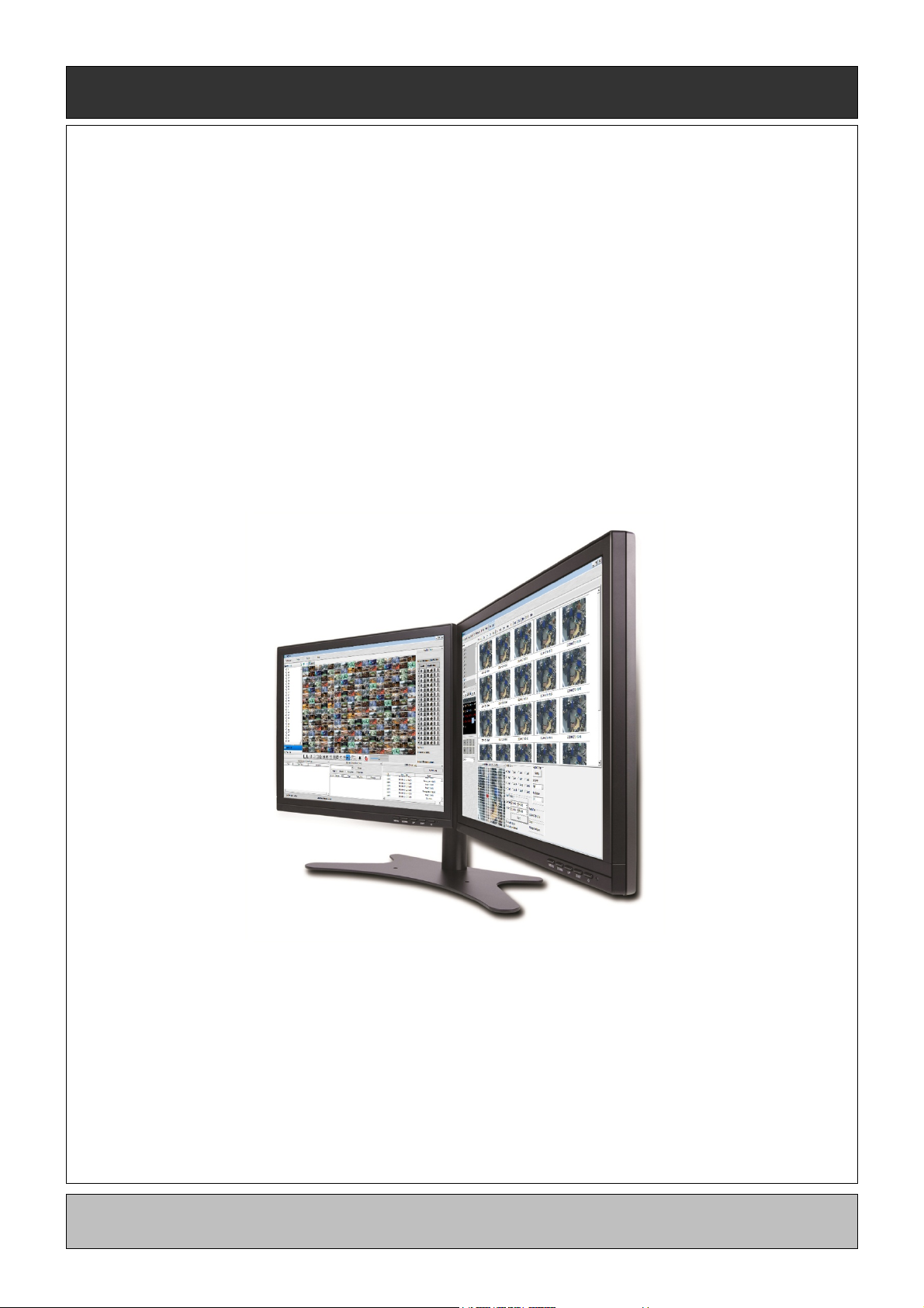
CMS Pro
Full-featured Enterprise Class Surveillance Solution
User`s Manual
This document contains preliminary information and is subject to change without notice.
75
Page 2

6. CMS Pro
6.1 CMS Pro Features
6.1.1 Introduction
The CMS Pro is a central surveillance system solution that monitors multiple sites with video, audio and event signals
from DVRs over networks.
The software supports different windows of live viewer, playback player, interactive map viewer, various search panes
and event signal monitoring panes.
6.1.2 Features
This program does not limit the number of units to register and monitor. The program displays up to 512 live videos; up to
256 channels on one screen and 256 channels on the other screen. The program supports as many monitors as a PC
supports. Users may open windows or panes of live video displaying, data playing, event signal monitoring, map displaying,
etc. Users can compose the central management system by choosing required widows or panes.
The software supports different windows of live viewer, interactive map viewer, and event signal monitoring panes.
The program displays event signals in real-time by connecting to devices over the network.
On the program, users may control PTZ cameras and relay outputs on the server or DVR. By attaching microphone and
speaker system to devices on site, users may make bi-directional audio communication over the network.
The map supports multi-layer structure, so that each map on different layers can respond interactively. On the map, users
may lay out icons of each device. Event signal triggers the icons on the map to blink, so that users may monitor event
signals on the map. And Users can check the live view of individual camera on the map by clicking the video icon.
With 5 different types of search function, users can search the recorded data according to user’s needs.
WARNING
DUE TO A LIMITATION OF A PC, CONNECTING MORE THAN 16 HD-SDI (FULL HD) CAMERAS MAY RESULT IN
MALFUNCTIONING OF THE SOFTWARE. TO CONNECT MORE THAN 16 HD-SDI (FULL HD) CAMERAS, PLEASE ENABLE
DUAL STREAMING OPTION ON THE DVR.
6.1.3 System Requirements
CMS Pro may not run properly if the PC does not meet minimum requirements. Other programs should not run on the same
PC where this is running. Otherwise, CMS Pro software may not perform as designed.
Minimum Recommended
CPU
Main Memory
Video Memory
Display Resolution
HDD Storage Space
Network
Operating System
Others
Intel Core i5 Intel Core i7
2GB 4GB or higher
1GB 2GB or higher
1024ⅹ768 (with 32bit color) or higher
160GB or higher
100~1000 Mbps Fast Ethernet
Windows XP Professional SP3 / Windows 7 (32/64) / Windows 8 (32/64)
DirectX 9.0 C or higher
76
Page 3
6.2 Installation
6.2.1 Software Installation
Please follow the program installation procedures below.
① If an old version of CMS Pro program was installed, it is recommended to completely uninstall or delete the old version.
② Insert the provided CD in a PC.
③ Run the CMS Pro Setup.exe file.
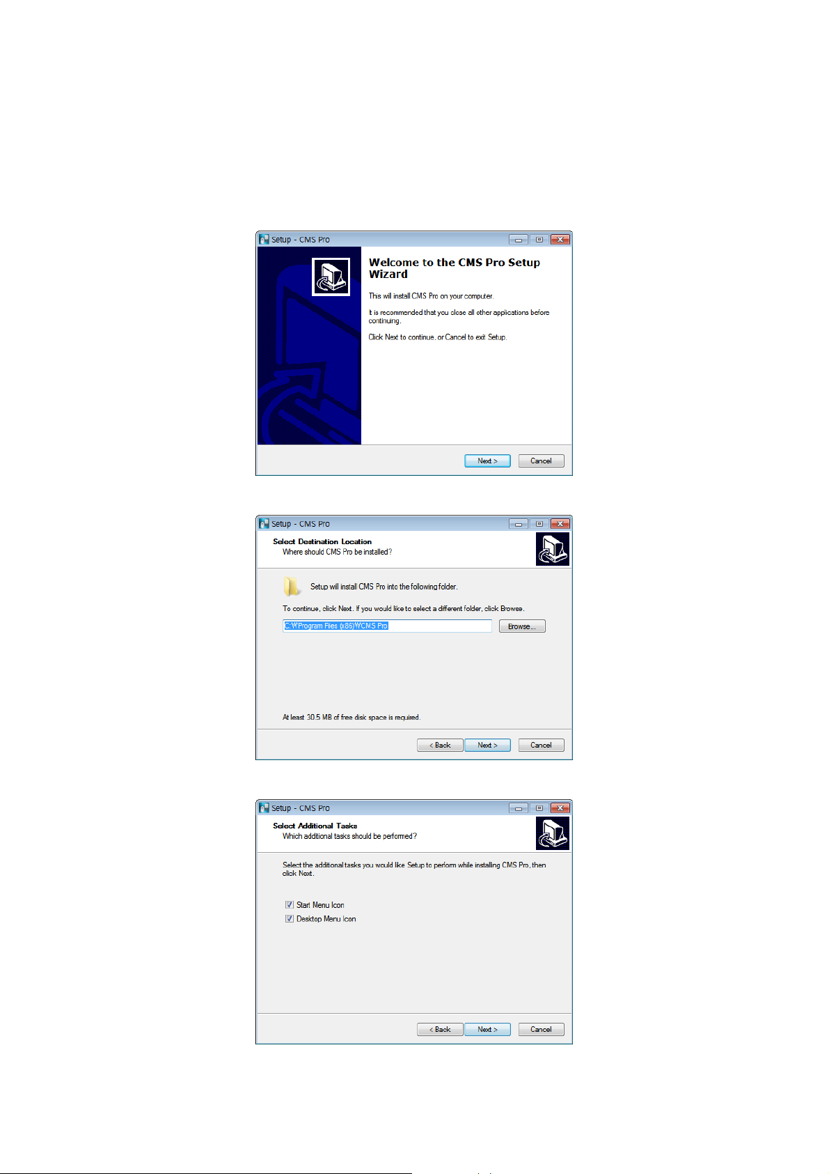
④ When the following screen appears, click “Next.”
⑤ When the following screen appears, select folder and click “Next.”
⑥ When the following screen appears, select the check box according to user’s preference and click “Next.”
77
Page 4
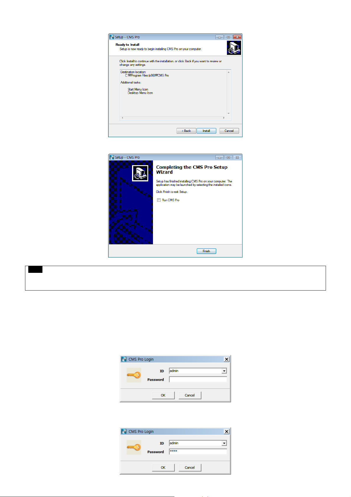
⑦ When the following screen appears, click “Install.”
⑧ When the following screen appears, click “Finish” to complete the installation.
NOTE
If the PC has a previously installed CMS Pro, the installer may ask whether to overwrite the existing DB or not. The DB
contains setting values on the program. If desired to maintain the existing values, click ‘No’ button.
6.2.2 Login
6.2.2.1 Login Process
Open the CMS Pro. Users may open it by selecting the execution file through ‘Start’ menu [Start] – [CMS Pro] or by double-
clicking the execution icon on the desktop.
Select a user ID in the ‘Login’ window. Users may see the entire list of IDs that are registered into the program by clicking on
the drop-down menu in the right-side. Initially, only the Administrator is registered as default.
Enter the corresponding password with the selected ID. The default password of the ‘Admin’ ID is ‘1111’. Administrator may
change the password in the program.
78
Page 5
NOTE
Users may change the password in [Setup] – [Change Password] menu. For the detailed information, please refer to the
‘Chapter 6.4.7 Change Password’ page.
The CMS Pro saves settings and layouts on the program of the current user when the program is closed.
6.3 Menu
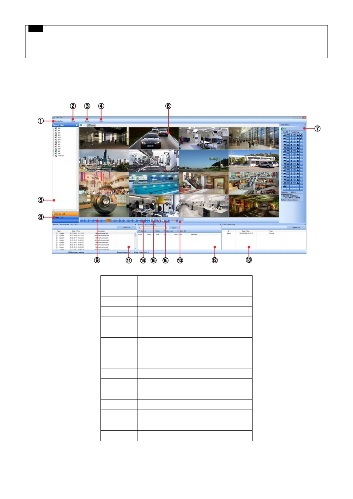
Below shows the brief explanation of each part on the screen.
1 Application
2 View set
3 Setup menu
4 Help menu
5 Server list pane
6 Display windows
7 Health check pane
8 Map list pane
9 Screen split selection icons
10 Audio control bar
11 Remote device system log pane
12 Remote device event log pane
13 CMS system log pane
14 Sequencing
15 Event Beep On / Off
16 Audio Status icon
79
Page 6
6.4 Setup
6.4.1 Local Setup - Device
Please make sure the network setting of DVR has been done properly prior to the remote connection setting.
6.4.1.1 Remote Site Connection Setup
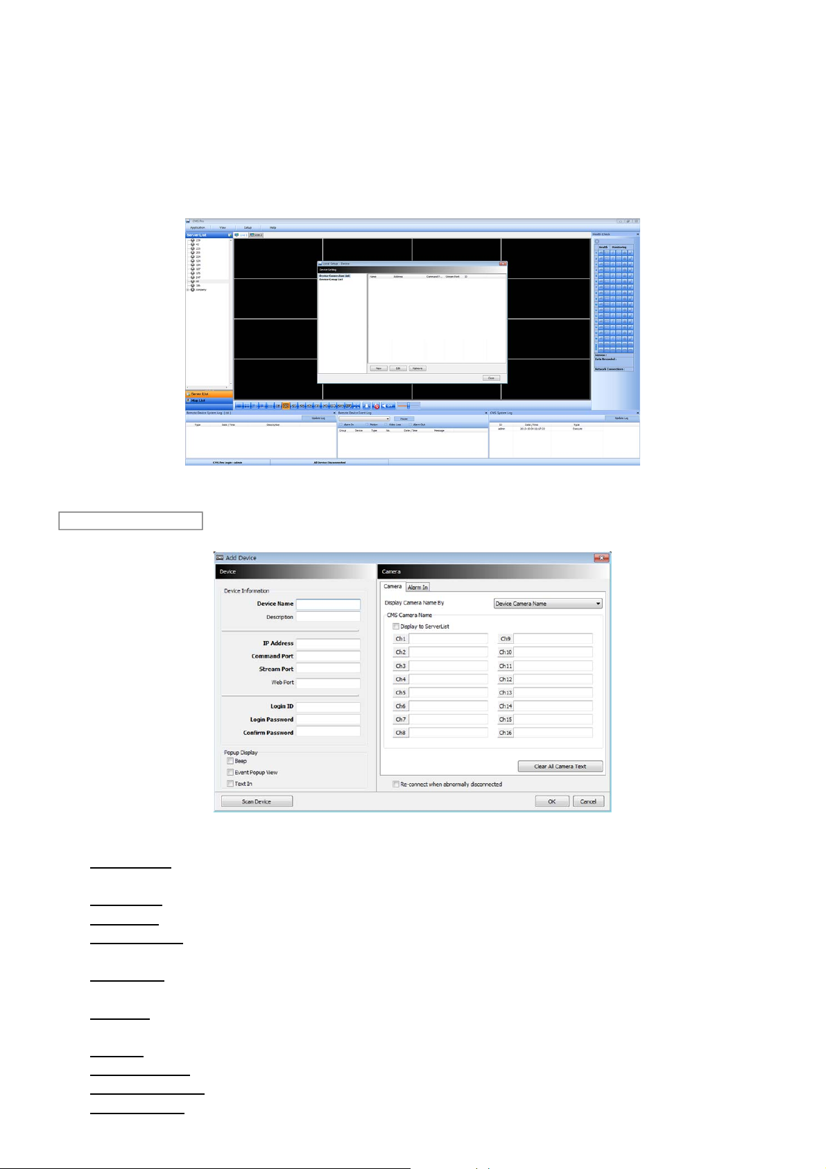
Click Setup – Local Setup – Device to enter the setup and a dialog will pop up as below picture.
6.4.1.2 New Device Register
Device
Select “Device Connection List” on left-hand side and click [New] to register new devices.
Describe the connection information as below. A user must fill in where information requested in bold.
- Device Name: Type the DVR name to be displayed in the server list pane. Please note that this name has no relation to
the ID registered in DVR. Users may create a name to be easily distinguished.
- Description: Type brief description of the site
- IP Address: Input IP address or Domain Name of DVR (check from the SETUP>DEVICES>Network in DVR)
- Command Port: Input Administrator’s number among port numbers set in DVR (check from the
SETUP>DEVICES>Network in DVR). Default port number is 5920
- Stream Port: Input Video/Audio number among port numbers set in DVR (check from the SETUP>DEVICES>Network in
DVR). Default port number is 5921
- Web Port: Input Web number among port numbers set in DVR (check from the SETUP>DEVICES>Network in DVR).
Default port number is 80.
- Login ID: Type authorized ID of the DVR. Default ID is admin.
- Login Password: Type correspond password of the ID. Default Password is 1111
- Confirm Password: Retype the password to confirm
- Pop up Display: A user can set both video and text-in pop up or beep on corresponding channel when event occurs.
80
Page 7
Camera
Choose a camera name between DVR and CMS setting or both.
- Device Camera Name: Display camera name of DVR.
- CMS Camera Name: Display Camera name of CMS.
- Both (Device-CMS) Camera Name: Display both as [DVR name]-[CMS name].
If users mark the “Display to Server List”, camera name is displayed in the server list.
Type the name of each camera in “Camera Name” item.
Users will be able to type not only in English but also in their own languages.
It is possible to erase all names by clicking “Clear all names”.
Save and close the setting panel by clicking “OK”.
If users wish to exit without saving, then click “Cancel”.
If users mark the “Re-connect when abnormal disconnected”, CMS Pro will automatically verifies the network condition, then
tries reconnecting to the site.
Alarm In
Alarm In name setting on CMS, when Alarm In event occurs.
- If users check “Display to Event Log” registered name shows on event log.
- “Clear all Text” : remove all registered name
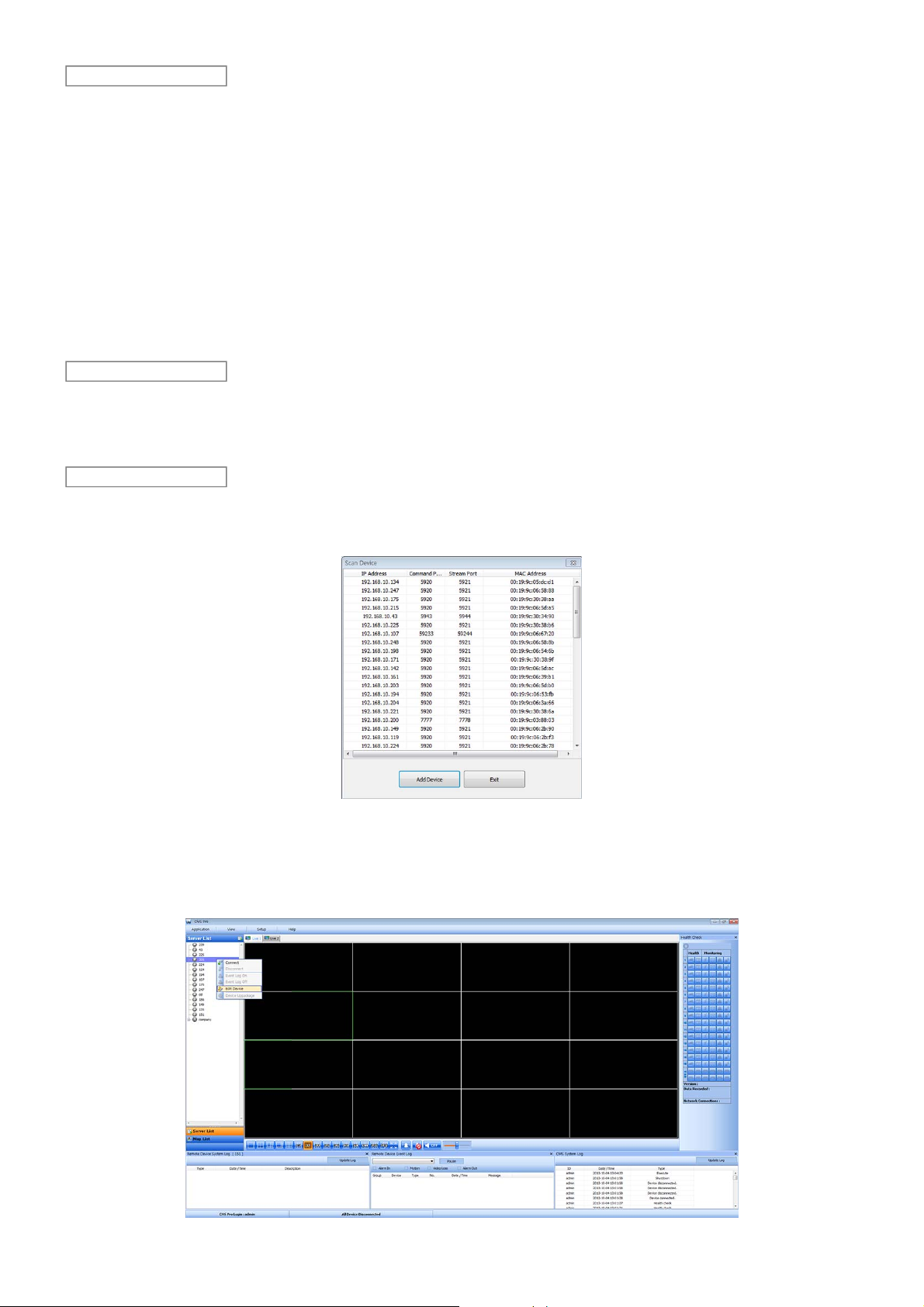
Scan Device
This function automatically detects and DVRs/Servers which are connected under the same local router as the PC.
Click “Scan Device”, then following will pop up. Selected desired DVR and click ‘Add Device’, and then type a password
accordingly.
6.4.1.3 Edit Registered Site
Select a site to adjust on local setup window and click “Edit”
Change the setting then click “OK” to save and exit.
Alternately, users can also edit the site by right clicking the mouse on the server name in the Server List.
81
Page 8
6.4.1.4 Remove Registered Site
Select a site to delete on local setup window and click “Remove”
The site will be removed on the local setup window.
6.4.2 Device Group Setup
It is possible to make a group of multi-devices for user’s convenience.
- Users are able to combine multiple devices as one group of connection for easy control.
- Users are able to extract the cameras from registered DVRs to make own group of display.
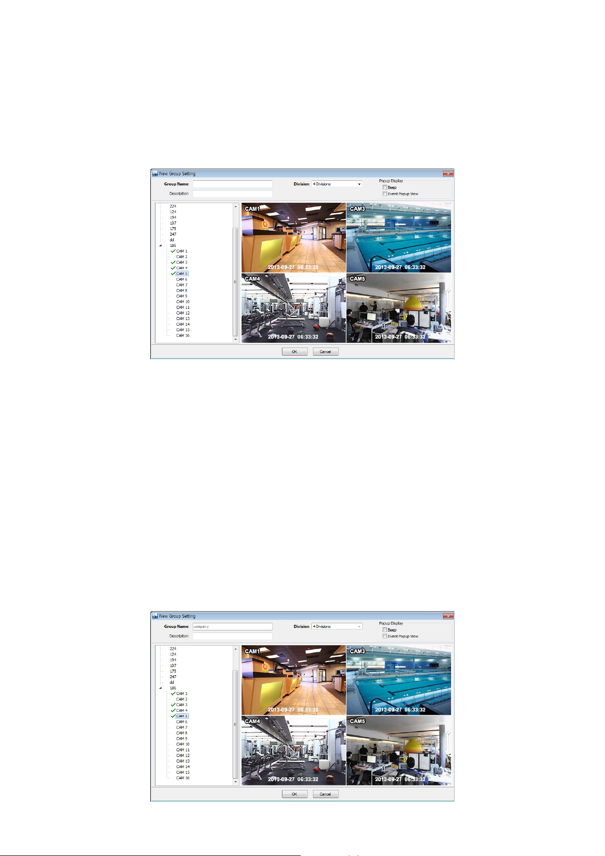
6.4.2.1 New Grouping Setting
Click Setup – Local Setup Device – Device Group List to add/edit a group
Click “New” to set up the Group Name, select Division (from 4 to 144), and type the Description.
Select the site from the server list in the left-hand side of the window.
Right mouse click and click “connect” on the site or double clicking the device will show the tree of cameras and here users can
extract the channel they want.
To add the channels into new group, drag & drop or double click on the camera.
Users are able to continue to extract and add the channel by connecting other DVRs.
Click “OK” to save and exit.
Users are able to set the pop up display function.
The newly added group will be displayed under ‘Server List’ when you go back to live screen.
6.4.2.2 Edit Group Setting
Select a group to adjust on Group Setting window then click “Edit”
Change the setting then click “OK” to save and exit.
Right click on server list and select the “Edit Device”, and then following pop up window will show up. Users are able to set the
“description” and Popup Display
82
Page 9
6.4.2.3 Remove Group Setting
Select a group to delete on Group Setting window then click “remove”
The group will be removed on the local setup window.
6.4.3 Local Setup - Environment
This enables users to adjust the default setting of CMS Pro software for user’s convenience.
6.4.3.1 System
Users are able to check the current version of the software.
Users are able to select the language among English, Korean, Japanese, Russian, Turkish, Finnish, German and French.
6.4.3.2 Viewer
Audio
- Users are able to control the Audio volume.
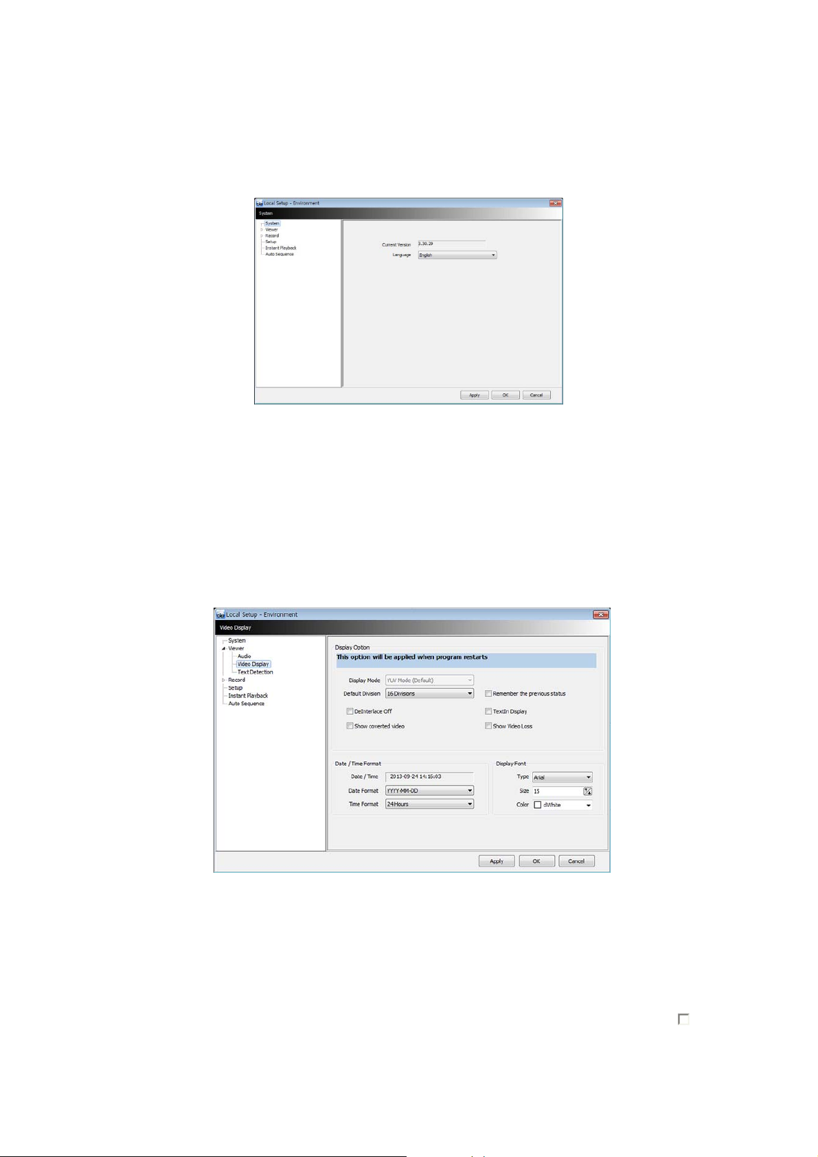
Video Display
Users can adjust and set the environment of the Display window.
The Display option will be applied after program restarts and the contents are as below.
- Display Mode: It shows the format of display and YUV Mode is the default and it is not adjustable.
- Default Division: Users can select the number of division of display channels when the program initially displays the
screen. (from 1 to 144 division)
- Users are able to save division of display by marking the “Remember the pervious state” check box.
- Deinterlace Off: This function changes playback display into Progressive Scan or Interlace Scan. Uncheck ( )
Deinterlace Off, then box will display as the Progressive Scan and shows the better picture quality.
- Show converted video: if this box is checked, covert cameras from DVR will show up.
- Text-In display: Text data will be overlaid on live and playback.
- Show Video Loss: Popup window will display, if video loss occurs on the connected DVR.
83
Page 10
NOTE
If users check “Show covert video” box, this setting will be applied to playback as well.
NOTE
All changes made above will be applied after program restarts.
Date / Time format: Users can adjust and set the mode of date / time display in accordance with the location.
- Date/Time: show current time.
- Date Format: select the date format among YYYY-MM-DD/MM-DD-YYYY/DD-MM-YYYY.
- Time Format: select the time format between 24Hours/ 12 Hours AM/PM.
Display Font: Users can change the font of the name and display time of each channel.
- Type: select the type of font between Arial and Courier.
- Size: select the size of the font from 10 to 20and the default is 15.
- Color: select the color among 16 different colors.
Text Detection
When the software can pop-up a notice windows when a certain text is detected from a DVR that has an attached
Text/POS device.
- Device: choose a device
- Message: add message like ‘VOID’. (When added message – ‘VOID’ – occurs from DVR, window will pop up.)
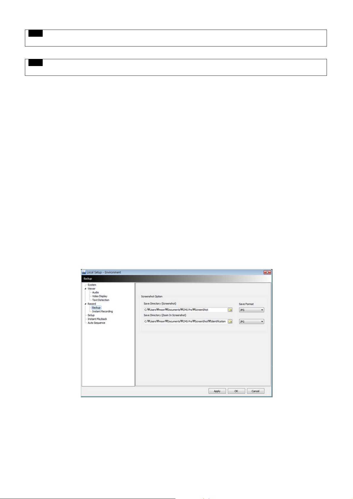
6.4.3.3 Record
Backup
Users can customize the storage path of the image file of Screenshot or Zoom in Screenshot by typing the path or clicking
the folder icon.
- Save Directory (Screenshot): Select the save directory by designating the folder in the PC and save format between bmp
and jpg.
- Save Directory (Zoom in Screenshot): Select the save directory by designating the folder in the PC and save format
between bmp and jpg.
84
Page 11
Instant Recording
Users can customize the storage path of the instant recording file by selecting HDD installed in PC.
- Select Drive: Select PC’s HDD where instant recording file should be saved from the drop down menu and click “Add”. It will
show Drive type, Free Space and Total Space of selected HDD.
- Storage List: Added HDDs can be prioritized or deleted. Use Up and Down arrow to prioritize and “Delete” to remove HDD from
the list.
NOTE
Instant Recording will be automatically stopped when less than 10GB is left in the directory.
NOTE
Please refer to Chapter 6.7.2.9 Instant Recording.
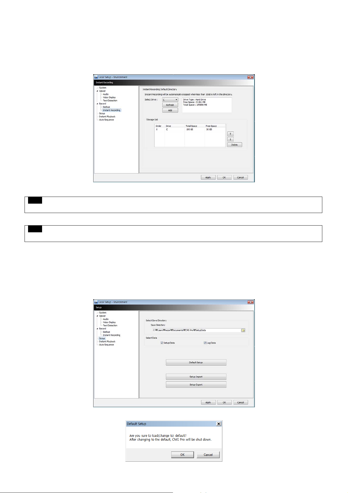
6.4.3.4 Setup
Users may save the current CMS Pro configuration data as a file and import it later to the same PC or another one.
Select Save Directory: Users can select the save directory of setup data or log data by designating the folder in the PC or other
storage device and the change of the directory will be applied only after clicking “OK” button and exit.
Select Data: Select data which users would like to save in the storage devices.
Default setup: Initialize the setup to factory default. Click “OK” to exit the program.
85
Page 12

Setup Import: Copy the Menu setup stored in USB memory stick (or PC HDD) into DVR. Please plug in the memory stick and then
click ( ) Import.
Setup Export: Store the Menu setup of DVR in USB memory stick (or PC HDD). Please plug in the memory stick and then click ( )
Export.
Apply: Click the “Apply” button to apply the settings.
6.4.3.5 Instant Playback
Instant Playback: Users are able to see the recorded data easily by using instant playback function.
Set the time from which the recorded data is displayed.
Instant Playback starts from the last preset time. (1, 3, 5, 10, 15, 30Min, 1, 3Hour, Default is 3Min)
For example, if 5 Min is set as a playback period, then users are able to see the last 5 minute’s data from the current time.
To activate the Instant Playback, just right click on a live screen and select ‘Instant Playback’.
6.4.3.6 Auto Sequence
Auto Sequence: Users are able to switching the camera view and setup the dwelling time.
Set the dwelling time by clicking the to increase and decrease duration. (3 to 60 seconds).
6.4.4 Local Setup - Account
When more than 2 users need to access CMS Pro, multiple User Accounts and its authorization can be set in this menu.
This setup is only permitted to Admin account holder.
86
Page 13

6.4.4.1 Add User Account
Click “New” button and the following will display.
Type: Select one of the two types of user account, Manager and User from the drop-down menu.
- While Manager Account allows all of the authorization to be controlled, User Account is permitted to set only Search, PTZ control,
and E-map functions.
Create a User name and Password and then type Description of the account.
Mark the authorization check boxes ( ) to allow.
- It is possible to give an authorization selectively to the individual user account.
- “Check All” grants all the authorizations and “Uncheck All” deprives all the authorizations.
Click “OK” to save and exit.
6.4.4.2 Edit User Account
Users are able to adjust its Authorization and Password from EDIT button.
All the procedures are same as Add User Account.
6.4.4.3 Remove User Account
Users are able to remove the existing account.
Select an account to delete then click “REMOVE” button.
6.4.4.4 Login Setting
This function protects any activities of all Manager/User accounts by asking ID and Password prior to the fulfillments.
Select the activities from the list ( ) and click “Apply” to save.
6.4.5 Local Setup – E-map
Users are able to create various E-maps and it enables monitoring both Live and Playback screen.
87
Page 14

6.4.5.1 Registering a New E-map
Click “New” Tab to set up the E-Map.
In order to load an image of the map, click “Load Map Image” that users would like to use as an E-Map.
Users should select the image format between BMP and JPG.
Place the icon of cameras, audios and alarms on the map. Each icon’s detail is as below.
- Box Camera: Generally indicates as Outdoor camera.
- Dome Camera: Generally indicates as Indoor camera.
- Alarm/Sensor: The icon is blinking on when the alarm in is activated.
- Audio: Users can hear the audio in the site by clicking the icon after setting the E-map.
- Relay: If users click the icon, the light is on the icon and the attached device on Relay such as siren and buzzer will be
activated in the site.
- Insert text box: Users are able to put description in the map using the Text Box.
Select component
- , , , , , Click the icon you want (then the icon turns to orange color) and click again on
the place you’d like to locate on the loaded image.
- Users can rotate the icon to the direction that they want and move to other places by dragging.
88
Page 15

Select Size: Size of the icon varies from 24*24, 32*32 to 48*48.
Edit Name: Type the name of the icon and click the “Apply” to change the name.
Reposition: The icons which are set up on the map can be repositioned into the right place even if the map size is changed
(enlarged/reduced).
Delete All Components: By clicking this button, users can delete all the components in the map at once.
Font: Change the font of the text of the icon.
- Click “font”, then submenu will display.
- Users can select the font style, color, size, and other effects.
- Check “Apply to All” to apply the change to all the components.
Click “File” Tab to continue to set up the E-map.
Type a name of E-map when you finish map setting in “New” menu.
Click “new” to add a new location in Location list. If the other location is already saved, then select the location from the list.
Select type among Outdoor, Floor, and Room.
- Users can set up the hierarchical E-map, if necessary.
- For example, after setting up the floor map, room maps are added under the floor map.
DVR Name: Select the specific DVR from the list to connect E-map.
Users are able to check the E-map and its hierarchical structure from the “Registered E-map list”.
- Here, users are able to load the map, delete the map and show map viewer by clicking mouse right button on the map list.
89
Page 16

Click “Save” to save and exit.
6.4.6 Remote Device Setup
Select a device to enter device’s configuration and Click “OK” then the web browser will pop up as below.
Enter ID and Password to open Remote Device Setup page and following page will display.
Web server port (default, 80) should be port forwarded to use remote device configurations.
NOTE
Remote Device Setup menu shows the same menu interface as the DVR’s local menu. Please refer to Chapter 4. Setup for detailed
information.
90
Page 17

6.4.6.1 System
Refer to 4.2 System for more detail.
6.4.6.2 Device
Refer to 4.3 Device for more detail.
6.4.6.3 Record
Refer to 4.4 Record for more detail.
6.4.6.4 Relay
Refer to 4.5 Relay for more detail.
NOTE
Some settings cannot be modified remotely.
NOTE
The changed password cannot be restored. Please keep and remember not to lose!
6.4.7 Change Passw ord
Users are able to change the using password of the ID, when they open the software. This is not related to any DVR’s login
password.
- Password: input the current password.
- New Password: input the new password.
- Confirm Password: confirm the new password.
NOTE
User “ID” cannot be modified.
6.4.8 Help
6.4.8.1 About
The version of CMS Pro can be checked here.
6.5 View
The viewer of this program is composed with 5 types of different panes.
- Server List, Remote Device System Log, Remote Device Event Log, CMS System Log and Health Check.
91
Page 18

6.5.1 Server List
When the device is registered, then it is displayed on the Server List.
If uncheck “Visible” in the server list menu, then the list will not be shown.
Check “Left” or “Right” to move the list to left or right side of the screen.
6.5.2 Remote Device System Log
User can check the system log of the device in this menu.
Type, Date/Time/Description can be checked.
The contents in the parenthesis show the name of the device. Ex) [Demo]
Check “Visible” in the Remote Device System Log menu to see the menu or uncheck “Visible” in order not to see the menu.
Click the “Update Log” button to update the log.
6.5.3 Remote Device Event Log
User can check the event log of the device in this menu.
Check “Visible” in the Remote Device Event Log menu to see the menu or uncheck “Visible” in order not to see the menu.
Users can select the registered device from the drop down box menu.
Alarm In / Motion / Video Loss / Alarm Out can be selected separately as Event. (More than 2 events can be selected at the same
time.)
And by clicking “Event log On/Off” after right mouse click on the device in the server list, users can check/uncheck all the events at
once.
When the event operates, the event log will show the information of the event in the list.
If click the pause button in the menu, then event log will be stopped.
Click the resume button to resume the system event log. (The log data will be lost during the pause.
92
Page 19

NOTE
The Remote Device Event Log is on when the “pause” is shown while the log is stopped when the “resume” is
shown in the menu.
Double click the detected “Alarm In” or “Motion” event in the remote device event log to check the video of the event.
Click the “Refresh” button to refresh the data.
Click the right mouse button on the registered device to on/off Event Log in the Server List.
A user selects “Event Log Off”; all event logs will be unchecked on Remote Device Event Log panel.
6.5.4 CMS System Log
This is the log menu where users can check the log information of the CMS program.
Check “Visible” in the CMS System Log menu to see the menu or uncheck “Visible” in order not to see the menu.
Click the “Update Log” button to update the log.
User can classify the Manager and User by checking the ID and get the information of connect/disconnect and shutdown of the
user.
6.5.5 Health Check
This is the menu where users can easily check the overall status of a device.
93
Page 20

Check “Visible” in the Health Check to see the menu or uncheck “Visible” in order not to see the menu.
Left mouse click on the device in the server list to see the information of health check.
HDD Status
- HDD is not connected and cannot be added.
- HDD is connected.
- HDD is not connected currently but can be added.
- An error occurred in HDD.
Camera Status
- Camera is in covert mode.
- Camera is connected.
- Camera is not connected currently but can be added.
- Camera is not connected and cannot be added.
Recording Data Status
- The channel is not being recorded because it’s not supported.
- The channel is being recorded.
- The channel is not being recorded currently but can be recorded later.
Motion Status
- Motion is not activated and supported.
- Motion is being activated.
- Motion is not activated but can be activated later.
Alarm In Status
- Alarm In is not activated and cannot be added.
- Alarm In is being activated.
- Alarm In is not activated currently but can be added later.
Alarm Out Status
- Alarm Out is not activated and cannot be added.
- Alarm Out is being activated.
- Alarm Out is not being activated but can be added later.
Relay Out Status
- Relay Out is not activated and cannot be added.
- Relay Out is being activated.
- Relay Out is not being activated but can be added later.
94
Page 21

6.5.6 Show All Window s
This function will make visible all the invisible window panes.
6.6 Application
6.6.1 Search
There are five different types of search menu; Timebar, Event, POS/ATM, Thumbnail and Smart Search
The detailed information and directions is described in chapter 6.8.
6.6.2 Exit
If users wish to exit the program, then click the “Exit” in the Application menu.
95
Page 22

6.7 Live (Live Video Monitoring System)
6.7.1 Overview
This program is to display live video from multiple channels in customized screen format.
The program is based on user friendly interface. Users may configure the entire program and open or close the panes and
screens in the program.
The information of the device can be checked and monitored in real time.
The overall information of recording/live view can be checked.
‘Login Display’ pane is to display the current user ID, authority group, data and time information.
Dual, Triple monitor can be available and the quadruple monitor can be available by using splitter.
Two live panes. 256 channels for each pane.
6.7.2 Live Monitor Menu
The following functions are operated when the right mouse button is clicked on the screen.
6.7.2.1 Full Screen On
Click “Full Screen On” to make selected channel into a full screen.
Click “Full Screen Off” to exit the full screen.
6.7.2.2 Auto Sequence
Users are able to set the auto sequence.
When users set the “Auto Sequence” display mode, screen will change to 1 channel display mode and channel will be
changed by user’s setup. For more information Please refer chapter 6.4.3.6.
96
Page 23

6.7.2.3 Instant Playback
Instant playback is available in both Live1 and Live2 pane, but screen capture is available in either live1 or live2.
After right mouse click, move the mouse cursor to “Instant Playback”. Then, play and setup menu will display.
- Play: The recorded video of the pre-setup time will be displayed in the playback viewer.
- Setup: The time of instant playback can be setup in this menu, from 1minute to 3hours.
(1Min, 3Min, 5Min, 10Min, 15Min, 30Min, 1Hour, 3Hour. The default time is 3Min.)
NOTE
Users can also set up the Instant playback in the menu, “Local Setup – Environment”.
The image capture is supported in the instant playback viewer by clicking right mouse button on “Capture Image.”
NOTE
For more detailed information of captured image, please refer to the Chapter 6.7.2.6 “Screen capture & Image”.
6.7.2.4 Digital Zoom
To use digital Zoom, please make the display as 1CH.
Right click on the mouse and select Enter Digital Zoom.
To zoom in and out, please use the display function at the corner of the channel Display or click and drag the area wish to
zoom in.
Zoom area can be moved by dragging the position from the corner box.
97
Page 24

Zoom in / out function
Zoom In
Zoom Out
Zoom Area: The Screen will revert to x4 digital zoom screen.
Zoom Area
NOTE
Digital Zoom function can be only used when the display is on 1Ch mode.
The digital zoom function is able to zooming approximately x32.
6.7.2.5 PTZ Control
After right mouse click on the channel that PTZ camera is connected, select “PTZ control”.
Users can designate the certain position and set the name by using “Preset” function.
Up to 255 presets can be designated.
98
Page 25

Zoom
- Zoom in
- Zoom out
Focus
- Near Focus
- Far Focus
Iris
- Iris Open
- Iris Close
Preset
- Set Preset
- Go to Preset
- Drop down menu: Select a preset number which is set in the camera.
- Preset Name: Save the selected preset name.
6.7.2.6 Screen Capture & Print
After right mouse click, select “Capture & Print Screen”
The brightness, contrast and saturation can be adjusted to store and can be printed directly.
NOTE
Image adjustment is only possible on the last captured image.
Users are able to save the captured image by clicking “Save as Image”.
Create a name of captured image and select the image type as BMP or JPG
Users are able to choose the folder where they wish to store the image.
Click “Show Captured Image” to show the captured images.
Users can even recapture the part of the captured image by dragging the place users want.
Click “Print” button to print all the captured images at once.
If users want to print the image one by one, then click the “Print Preview” button.
- Users can type the title in the text box on the top
- Add Text: Users can add the description in the text box on the bottom.
- Delete Text: Delete the last written text at once.
- Delete all: Delete the all the text in the captured image.
99
Page 26

Click “Hide Captured Image” to hide the captured images.
6.7.2.7 Audio On/Off
Right click and select Audio On/Off to turn on/off audio from the channel.
Audio On/Off function is applied to only one channel out of all connected channels.
- Once audio is on “ ” will be changed to show connected audio channel. “ ”
6.7.2.8 MIC On/Off
Click right mouse button to turn on/off microphone of PC.
Users can deliver the audio through the speaker connected to DVR by sending the audio from PC where CMS Pro is activated.
6.7.2.9 Instant Recording
Click right mouse button to activate the Instant Recording.
In the Instant Recording, there are three choices of start recording, setup and open folder.
Click Start Recording to record the particular channel that user wants.
100
Page 27

If a user wants to have password for the archiving file, please click ‘Use Password’ and type the password that users want to use.
If users click ‘OK’, it will start recording of that specific channel.
When users want to view the archived file, please choose “Open Folder”
It will open the saved directory of the file.
When users double click the created file, password window will pop –up.
Please type the previous password that users entered in Password setup
When Users want to “stop recording”, click right mouse again and select Instant Recording and choose “stop recording”.
Choose “Setup” in the Instant Recording to set up the recording duration and default directory.
In the recording duration, users can setup the hours and minutes by clicking the “upside down arrows”
“Open folder” will allow a user to select the recorded files and play them.
101
Page 28

6.7.2.10 Display Option
Users can set up the display of camera name and time in “Display Option”.
After right mouse click, check the “Show Camera Name” to display the camera name or uncheck the menu to hide it.
After right mouse click, check the “Show Time” to display time or uncheck the menu to hide it.
6.7.3 Screen Layout Control
Every menu pane can be relocated by drag and drop.
6.7.4 Change Division Display
From a single full screen to 256 channels, various combination of channel display is provided by clicking the icon at the bottom of
the screen.
6.7.5 Sequencing
Click the icon to switch the channel according to setup made in auto sequence in Local setup – Environment.
It is only supported one channel.
102
Page 29

6.7.6 Audio Volume Control
Users can control the audio volume using the bar controller at the bottom of the screen.
6.8 Search
6.8.1 Overview
5 ways of Search are available. (Time Bar Search, Event Search, POS/ATM (keyword) Search, Thumbnail Search, and Smart
Search).
NOTE
Search window cannot be closed during playback, also cannot be changed window size. Please close the window after stop.
Playback more than 2 channels at the same time is available only in time bar search.
6.8.2 Time Bar Search
Open a search window by clicking the “search” in the application menu.
Click the “connect” after right mouse clicking on the device list.
Once it is connected to the program, date, month and year of the recorded data is highlighted in the calendar.
The text box in the left-bottom side of the window shows the time of playback video.
The recorded data of a day is displayed as a colored bar on the time line at the bottom.
Users can easily search the recorded data by clicking on the time in the time bar.
103
Page 30

Users can change the speed of rewind and fast forward from x1 to Extreme. The actual speed may be limited by DVR’s network
uploading bandwidth.
Users can use Right click to access Audio On/Off, Digital Zoom and Capture and Print Screen.
- Audio On/Off: A user can enable audio function. If Audio is connected Audio Status will change.
- Enter Digital Zoom: A user can use Digital zoom. Please refer 6.7.2.4 Digital Zoom.
- Capture and Print Screen: A user can capture image. Please refer 6.7.2.6 Screen Capture and Image.
NOTE
Audio and Digital Zoom are supported only in 1CH display mode.
In the playback menu, users are able to search the data from the beginning of the day or from the cursor position.
Or just simply click on the time line users want, and then click “ ” button on the left.
Click “Archive” button to save certain channels as a video file.
104
Page 31

Select a start time, end time, file name, the location of the file, password and the cameras to store.
Click “Start EXE Backup” to start archiving.
NOTE
Archiving function can be initiated only in time bar search.
6.8.3 Event Search
Click the “connect” after right mouse clicking on the device and select the “Event Search”.
Check the event type which users wish to search among “Emergency”,” Alarm” and “Motion”.
(Users can select more than 2 event types at the same time)
Select a camera to search. (Only 1 camera can be selected in event search.)
Specify the start time and end time in Date/Time setting and click “Search” button.
To check the event that is detected on the right side of the search window, double click the event that users want.
6.8.4 POS/ATM Search
Click the “connect” after right mouse clicking on the device and select the “POS/ATM Search”.
Type the actual keyword that users want to find in the “POS / ATM” text box.
Select a camera to search. (Only 1 camera can be selected in this search.)
Specify the start time and end time in Date/Time setting and click “Search” button.
The detected text will be displayed in the right side of the search window.
Double click or click on the event (Text In) and click the play button “ ” to check the playback.
105
Page 32

Display Position – Users are able to select the text display option of the playback.
- Text Window: Only text will be displayed in the top right side of the search window during the playback.
- Overlay: The text will be overlaid on the playback video.
- Both: The text will be overlaid on the video and the text window as well.
- Hide All: The text will not be displayed in both video and the text window.
To check the event that is detected on the right side of the search window, double click the event that users want.
6.8.5 Thumbnail Search
Click the “connect” after right mouse clicking on the device and select the “Thumbnail Search”.
This search function provides the users with the snapshots of the recorded video by user’s definition.
Users are able to choose the duration of the playback in “Thumbnail Duration” from 1Min to 60Min. (1, 3, 5, 10, 20, 30 and 60Min)
The number of “Max Capture Count” can be setup as 32, 64, 128 and 256.
Specify the start time and end time in Date/Time setting and click “Search” button.
Double click the listed snapshot images to check and play the video.
Click “Stop Search” to stop the search and check the video to the stop time.
The video will be displayed in the “video display” panel at the bottom of the search window.
Users can move the panel around the screen and adjust the size of the panel.
6.8.6 Smart Search
Click the “connect” after right mouse clicking on the device and select the “Smart Search”.
Choose a camera to use for Smart Search
Users can select the area in an individual channel by dragging the certain area in “setting” menu.
(More than 2 areas can be designated in the setting pane.)
Specify the start time and end time in Date/Time setting and click “Search” button
If the movement is detected in the area, it will automatically display the snapshots in the search window.
Double click the listed snapshot images to check and play the video.
106
Page 33

Users are able to select the one from the 3 types of sensitivity level; Super, High and Standard.
6.9 E-Map
6.9.1 Overview
The ‘Map Viewer’ program is to display event signals over map images so that users may acknowledge event status more
easily.
Users may recognize event occurrence with visual notifications on icons over the map image and audible notifications on
speaker system of a PC. By clicking on the camera icons on the map, users may launch ‘Instant Viewer’ window.
To utilize ‘Map Viewer’ properly, users should configure map before running ‘Map Viewer’ program.
(Please refer to Local setup – E-map in chapter 6.4.5)
6.9.2 Controls
Users can load the Map Viewer which was set up “in Local Setup - E-Map” by clicking right mouse button on the map in the
map list.
Users can check the information of the device connected E-map in the right side of the Map viewer such as Device status,
name, IP / Domain, the maximum number of Camera, Alarm in / out and Audio.
6.9.3 E-map Camera – Instant Playback
Users are able to load the instant viewer by clicking the camera icon on the map.
107
Page 34

Full screen mode is available by clicking right mouse button and select “Full screen”.
Click audio icon to listen to the audio of the channel, if audio input connected.
Click the alarm out icon to release a manual relay signal to the site such as siren or buzzer
6.9.4 Alarm In/Out Control
The Alarm In icon on the map is blinking when the Alarm In equipment like sensor or detector is activated.
Click the alarm out icon to release a manual relay signal to the site such as siren or buzzer.
6.9.5 Audio
Click audio icon to listen to the audio of the channel, if audio input connected.
6.10 Uninstalling CMS Pro
Please click the “Uninstall” file in the CMS Pro folder in the PC.
Click the uninstall file and the following message box will pop up.
Click “OK” to remove the program and its components.
If uninstall is complete successfully, the following message will pop up.
108
 Loading...