

Page 1
www.avueinc.com
info@avueinc.com
HDBaseT Extender
Over Cat5e/6 Cable
HDMI-EX 250
HDBaseT HDIMI Extender
Over Cat5e/6 Cable
4
K
Ultra HD
HDBaseT HDMI Extender
Over Cat5e/6 Cable
4
K
Ultra HD
ReceiverTransmitter
Page 2
Dear Customer
only with dry cloth.
Ensure the unit is well ventilated.
3. To prevent risk of electric
plugs.
DTV/HDTV;
4K/1080P/1080i/720P/576P/480P/576i/480i
Features
Thank you for purchasing this product. For optimum performance and safety, please
read these instructions carefully before connecting, operating or adjusting this product.
Please keep this manual for future reference.
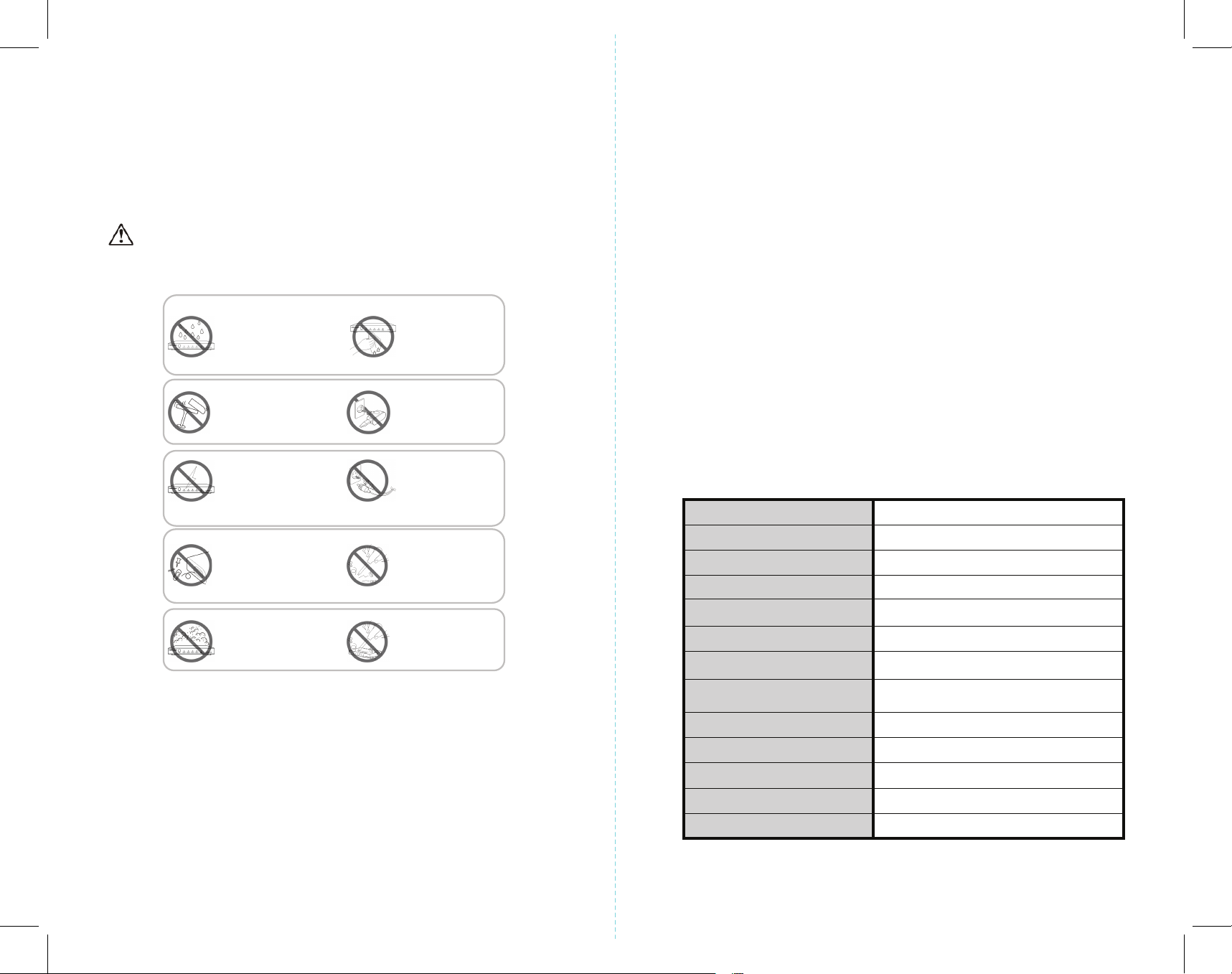
Warning
To reduce the risk of re, electric shock or product damage:
1. Do not expose this apparatus
to rain, moisture, dripping or
splashing and that no objects
filled with liquids, such as vases,
shall be placed on the apparatus.
2. Do not install or place this unit
in a bookcase, built-in cabinet or
in another confined space.
shock or fire hazard due to
overheating, do not obstruct
the unit’s ventilation openings
with newspapers, tablecloths,
curtains, and similar items.
4. Do not install near any heat
sources such as radiators, heat
registers, stoves, or other
apparatus (including amplifiers)
that produce heat.
5. Do not place sources of naked
flames, such as lighted candles,
on the unit.
6. Clean this apparatus
7. Unplug this apparatus
duri
ng lightning storms or
when unused for long
periods of time.
8. Protect the power cord
from being walked on or
pinched particularly at
9. Only use attachments
/ accessories specified
by the manufacturer.
10. Refer all servicing to
qualified service
personnel.
• One pair as a full functional module, no need for setting.
• Use single UTP/STP LAN cable (CAT-5E/6) to substitute HDMI cable to achieve
long distance transmission.
• UTP/STP cable termination follows the standard of IEEE-568B.
• Transmission distance reaches up to 250 ft. under the video format of 1080P
and 4K up to 150 ft.
• POC (RX powered by TX)
• HDCP2.2/1.4 compliant.
• Full HD support: 1080p@60Hz@48b/pixels, 3D and 4Kx2K
• With LED indicators to show the power status.
• With ESD protection inside.
• Mounting ears supplied.
• Transfer Bidirectional Infrared control signal together with the HDMI signal.
• Phoenix RS232 Port for rmware update or RS232 control signal transmission.
NOTE: Specications are subject to change without notice. Mass and dimensions are approximate.
Specications
Operating Temperature Range -5 to +35°C (-41 to +95 °F)
Operating Humidity Range 5 to 90 % RH (no condensation)
Input Video Signal 0.5-1.0 volts p-p
Input DDC Signal 5 volts p-p (TTL)
Video Format Supported
Output Video HDMI 2.0+HDCP1.4/2.2
Output Audio Support DTS-HD, Dolby-HD
Package Contents
HDBaseT Extender Receiver..........................................................................................................1Pc
HDBaseT Extender Transmitter....................................................................................................1Pc
12VDC power supply (RX can be powered from TX)...........................................................1Pc
Phoenix plugs for RS232 cable termination......................................................................... 2Pcs
IR TX unit........................................................................................................................................... 2Pcs
IR RX unit........................................................................................................................................... 2Pcs
Maximum Transmission Distance
250 ft. for 1080P, 150 ft. for 4K
Power Supply 12V2A
Poc Power from TX to RX over Cat5/6 cable
Power Consumption
2.5 Watts (TX), 5Watts (RX)
Dimensions 105mmH×71mmW×25mmD
Mass (Main unit) 0.7Kg / 1.54lb (Pairs)
1 2
Page 3

Panel Descriptions
How to Connect
1. TX (Transmitter)
1. RS232 Signal/ Firmware Switch
2. Cat5e/6 Out
3. HDBaseT Link Indicator
4. RS232 Output
1.HDMI Indicator
2.HDMI Output Port
3.IR RX Cable to IR-In Port
4.IR TX Cable to IR-Out Port
5.Power Indicator
6. DC Power Input
2. RX (Receiver)
1. RS232 Signal/ Firmware Switch
2. Cat5e/6 Out
3. HDBaseT Link Indicator
4. RS232 Output
Operation
Mode
Program
Normal
Cat5e/6 Out
1 2 3 4
Status
HDMI IN IR-In IR-Out DC/12V
1 32 4 65
Operation
Mode
Program
Normal
Cat5e/6 Out
1 2 3 4
HDBaseT Link
HDBaseT Link
1. Connect the HDMI input source (such as HD-DVD, PS3, STB etc.) to the
HDMI in port of Transmitter
2. Connect IR RX unit into the IR-In port of Transmitter
TX RX
3. Connect IR TX unit into the IR-Out port of Transmitter
4. Connect DC power to the Transmitter
5. Connect Transmitter to the reciever with Cat5e/6 cable
6. Connect the HDMI output (such as HD-LCD,HD-DLP) to the HDMI out port
of Receiver
7. Connect IR RX unit into the IR-In port of the Receiver
8. Connect IR TX unit into the IR-Out port of the Receiver
9. Use Phoenix RS232 port to set the rmware upadate.
Power
HDMI In
TX RX
TV Remote
Control
IR-In
IR-Out
DC /12V
Power
DVR
Transmitter
Cat5e/6 Cable
Receiver
(Go to How to Upadate Instruction)
Phoenix RS232
Matrix/ Source
IR-In
IR-Out
Remote Control
1.HDMI Indicator
2.HDMI Output Port
3.IR RX Cable to IR-In Port
4.IR TX Cable to IR-Out Port
5.Power Indicator
Phoenix RS232
Status
HDMI IN IR-In IR-Out
Power
1 32 4 5
3 4
HDMI Out
TV
Page 4

How to Change the Operation Mode
Built-in switches on HDMI Transmitter and Receiver are for bypassing RS232 signal or rmware
updating. To change the opertaion mode, move the buttom to the Normal side for RS232
transmission and move it to the Program for the rmwork update.
Operation Mode
Normal Program
How to Update the Instruction:
1. The user should receive a Firmware burn package, containing all software needed for burning
and updating the Firmware on the EEPROM.
2. Connect an RS232 cable from RS232 port of unit to PC.
3. Power the unit.
4. Extract the zipped le from the burn package to a directory (e.g. C:\dir_name).
5. Browse to the directory (e.g. C:\dir_name\) and double click the batch le Update Source.
bat (for TX) or Update Sink. bat (for RX).
6. A short description of the link created between the PC and the board appears on the screen,
followed by the burn progress percentage report.
7. A second stage of verifying the content of the EEPROM follows, also with a progress percentage
report.
2. Replacement parts: When parts need replacing ensure the servicer uses parts specied by
the manufacturer or parts that have the same characteristics as the original parts. Unauthorized
substitutes may result in re, electric shock, or other Hazards.
LIMITED WARRANTY LIMITS AND EXCLUSIONS
1. This limited warranty only covers failures due to defects in materials or workmanship, and
does not cover normal wear and tear or cosmetic damage. The limited warranty also does not
cover damages which occurred in shipment, or failures which are caused by products not
supplied by warrantor, or failures which result from accidents, misuse, abuse, neglect, mishandling,
misapplication, alteration, faulty installation, set-up adjustments, maladjustment of consumer
controls, improper maintenance, power line surge, lightning damage, modication, or service
by anyone other than a factory service center or other authorized servicer, or damage that is
attributable to acts of God.
2. Thereare no express warranties except as listed under “limited warranty coverage”. The warrantor
is not liable for incidental or consequential damags resulting from the use of this product, or
arising out of any breach of this warranty. (As examples, this excludes damages for lost time,
cost of having someone remove or re-install an installed unit if applicable, travel to and from
the service, loss of or damage to media or images, data or other recorded content. The items
listed are not exclusive, but are for illustration only.)
3. parts and service , which are not covered by this limited warranty, are your responsibility.
* NOTICE
Maintenace
Clean this unit with a soft, dry cloth. Never use alcohol, paint thinner of benzine to clean this unit.
PRODUCT SERVICE
1. Damage requiring service: The unit should be serviced by qualied service personnel if:
• The DC power supply cord or AC adaptor has been damaged
• Objects or liquids have gotten into the unit
• The unit has been exposed to rain
• The unit does not operate normally or exhibits a marked change inzX performance
• The unit has been dropped or the cabinet damaged.
5 6
Our company reserves the right to make changes in the hardware, packaging and any accompanying
documentation with out prior written notice.
 Loading...