

Page 1
The 2.0-Megapixel IP Bullet Camera Indoor/outdoor (PoE)
Description of The Device
The PCB board: The component parts ( the internal view ).
6 7 8 9 10
1. Plug Inlet: An AC 24V inlet that connects to an external power supply.
2. ETHERNET 10/100 Connector: This is a standard RJ-45 connector for 10/100
Mbps Ethernet networks. PoE (Power over Ethernet) function: Provides power to
the device via the same cable as used for the network connection.
3. Plug Inlet: A DC 12V inlet that connects to an external power supply.
4. GPIO: This is a 6-PIN connector including the Digital output/input, DC output
and GROUND items for connecting with external devices.
5. VIDEO OUT Connector: The connector provides the unit’s composite video
signals to a monitor. (This connector adjusts and improves the images.)
6. AUDIO IN: The connector is used to connect the audi o output from other device s
to the camera.
7. USB port: The user can use a USB devi ce cable to conne ct the IP camera to the
USB port on the PC.
8. AUDIO OUT: Provides the camera’s audi o signal to a speaker or stereo.
9. SD/ SDHC CARD slot: This is used for updating system software and archiving /
accessing critical images.
10. RESET: Recover to factory default.
1
2
3 4 5
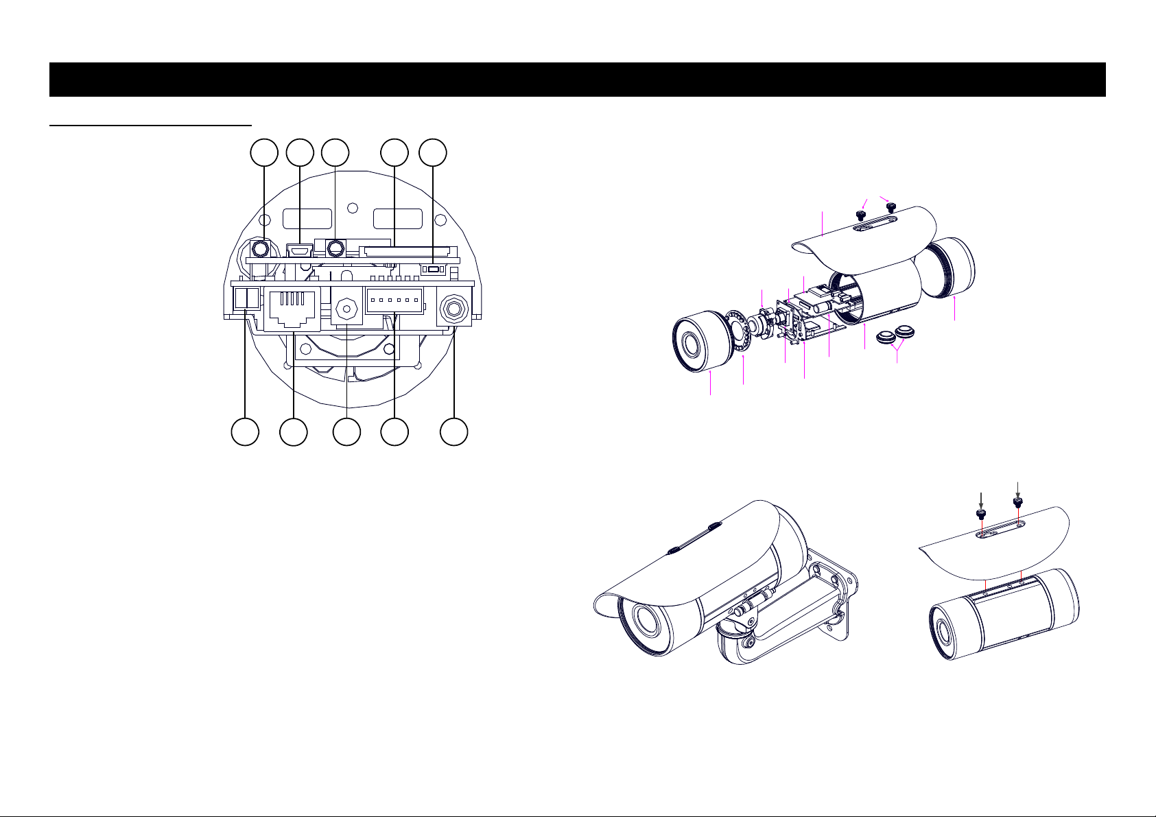
Dismantle the bullet IP camera to see its different parts. The picture here shows you
the internal component items making up the product.
FRONT CASE
LENS
SENSOR PCB
IR PCB
SUN SHIELD
SD PCB
FAN
POWER PCB
PCB PLATE
SCREWS
MIDDLE CASE
WATERPROOF RUBBER
Camera with bracket ( the external view ).
The picture here shows the camera's exterior, with the bracket screwed in and fixed
to it. The bracket enables you to easily mount the camera on a wall, turned at the
angle you want.
NOTE: Use the 2 screws to screw the sun shield (above) into the 2 extreme holes indicated in the
bullet camera (below) to get an unobstructed viewing angle.
Please don’t use the middle hole in the camera, as that will block the view.
REAR CASE
1 RMN0100560
Page 2

Please follow the steps given below to install, configure and set the IP Camera.
1. Check the IP class of your PC
Step 1: From the Start menu, point to Settings, and then click Control Panel.
Step 2: When Control Panel appears, double-click the Network Connections icon. The
Network Connections dialog box appears.
Step 3: Click the Protocols tab in the Network Connections dialog box.
Step 4: When the Local Area Connection Properties dialog box shows up, choose Internet
Protocol (TCP/IP) and click Properties.
Step 5: In the Internet Protocol (TCP/IP) Properties dialog box, choose Use the following IP
Address to indicate that you do not wish to use DHCP, and assign IP Address
192.168.1.200 with Subnet mask 255.255.255.0. Click OK when you finish it.
Step 6: Choose Close to finish the modification.
2. Install UPnP Packets of your PC
As described before, Microsoft Windows XP
we have to install some packets before we init ialize it. The following steps will help you to install
them.
Step 1: From the Start menu, point to Set Program Access and Default, and then click it.
Step 2: When the Add or Remove Programs dialog box appears, click the Add/Remove
Windows Components button.
Step 3: Check the Network Services in the Windows Component Wizard dialog box, and
then click Details….
Step 4: Check UPnP User Interface, and choose OK.
Step 5: When the original Network Component Wizard dialog box returns, click Next.
Step 6: After about one minute the UPnP installation will be done, and choose Finish to close it.
3. Turn on Services of your PC
After installation, we should turn on the relative services to start the UPnP protocol. The
following procedures will teach you how to do it.
Step 1: From the Start menu, point to Settings, and then click Control Panel.
Step 2: When Control Panel appears, double-click the Administrative Tools icon. The
Administrative Tools dialog box appears.
Step 3: Click the Services icon in the Administrative Tools dialog box.
Step 4: When the Services dialog box shows up, double click the SSDP Discovery Service
icon.
Step 5: Choose Automatic in the Startup type, and click OK to start it.
Step 6: When the Services dialog box appears again, double click the Universal Plug and
Play Device Host icon.
Step 7: Choose Automatic in the Startup type, press the Start button, and click OK to start it.
Step 8: Restart your system.
®
doesn’t start the UPnP service by default; however,
4. Set the static IP address in the IP Camera.
Step 1: Plug in its power connection.
Step 2: Plug the USB connector in your PC and in the USB socket in the rear of the lens.
Step 3: A window pops up asking if you want to "Run the program", "Open folder to view files",
or "Take no action". Choose "Run the program" and click "OK", and the "USB
configuration" window will pop up.
Step 4: Set the Network setting and type in the IP address you desire. Before you change the
IP address, you should note the factory default Static IP address ( 192.168.1.168 ).
Step 5: After changing the IP address, click the "Apply" button in the "USB Configuration”
window.
Step 6: A message pops up asking you to affirm the action as "OK".
Step 7: Click "OK", and remove the USB connection from your PC.
Step 8: Click "Exit" at the bottom of the "USB Configuration” window to close the window. Or,
choose the "Launch" button to see the local camera images directly.
Step 9: Before clicking "Launch", check your PC's IP address and use the Network connector
( RJ-45 ) to link up with your camera.
Step 10: If you can see the images, it means the IP setting is complete.
5. Scan IP Camera through “My Network Place”
Step 1: After your installation and starting services, the UPnP protocol will take effect. You can
scan all IP Cameras in My Network Place.
Step 2: Just double click the IP Camera icon, and the video live stream will pop up
automatically without assigning any IP address in Microsoft Internet Explorer.
6. Change the IP Camera's control and operational settings.
Step 1: Type in the IP address in the IE Browser. You will now see the IP camera' images.
Step 2: Use the buttons below the images to enter any other operational settings pages.
Step 3: When you change any setting, please don't forget to click the "Submit” button in each
page.
NOTE: Enable DHCP Function: This function can only work if the LAN, which the unit is
connected to, has a DHCP server. If the DHCP server is working, the IP Camera
will obtain an IP address automatically from the DHCP serv er.
NOTE: When only one unit of the IP Camera is connected to a comp uter or LAN, you can
freely assign an IP address for the IP Camera. For example, there is a range of IP
Camera IP addresses from 192.168.1.1 to 192.168.1.255. You can pick one for use
from the range of the IP. It’s not necessary to set MASK and GATEWAY; leave the
settings as default.
When an IP Camera is connected to a WAN, you must acquire a unique,
permanent IP address and correctly configure the MASK and GATEWAY settings
according to your network architecture. If you have any questions regarding
those settings, please consult a qualified MIS professional or your ISP.
2 RMN0100560
Page 3

The Alarm Wiring Diagram Hardware Installation
/
1. Plug in the power connection to the IP camera.
2. Plug in the IP camera cable.
3. Confirm the correct network connection status (PC/HUB/ IP camera).
4. In the PC IE Browser, key in the camera’s IP online to link up to the live first
page.
NOTE: The user can replace the desiccant pack
depending on how often the camera
interior has been opened to the
environment. Stick and fix a desiccant
pack to the inner side of the camera with
a two-side adhesive tape, then reattach
the cover of the camera.
WARNING
To prevent fire or shock hazard, avoid exposing this unit to rain or moisture.
Do not block ventilation openings.
Do not place anything on top of the unit that might spill or fall into it.
Do not attempt to service this unit yourself, as opening or removing covers may expose
you to dangerous voltage or other hazards. Please refer all servicing to your distributor /
retailer.
Do not use liquid cleaners or aerosols for cleaning.
To prevent fire or electric shock, do not overload wall outlets or extension cords.
PoE warning : If the PoE injector is used instead of the supplied power adaptor, all of the
wiring to and from the injector must be routed/ installed inside a building/ plant and never
routed/ installed outside of the building/ plant.
Please only select a power adapter or power certified by UL and marked at 24Vac / 60 Hz,
minimum 1A, class 2 or LPS.
The interconnecting cables should be placed inside the UL certified Outdoor Use
Conduits.
If the power supply is installed outdoors, it should be a listed rainproof / watertight class 2
LPS power supply or a listed power supply complying with UL60950 -1, part 1 and part 22.
The wiring method should comply with article 725 and article 300 in the national electrical
code for the class 2 circuit and wiring in duct.
The entire installation should be performed by qualified personnel.
Please do not look directly at the shining, reflecting surface of the camera housing.
Looking directly could result in eye uncomfortable.
This product should not be used for the same purposes as consumer electronic devices.
CAUTION
RISK OF EXPLOSION IF BATTERY IS REPLACED BY AN INCORRECT TYPE. DISPOSE OF
USED BATTERIES ACCORDING T O THE INSTRUCTIONS.
GND
12V+
Di -
Di +
+12V
Do -
Do +
+12V
3 RMN0100560
Page 4

Specifications
Model The 2.0-Megapixe IP Bullet Camera Indoor/outdoor (PoE)
Image sensor 1/2.7” Omni Vision 2M CMOS sensor
3.3~12mm Vari-focal board type (VGA type)
Lens
Camera
Image
Audio
Network
Alarm
Connectors
General
*Specifications are subject to change without notice.
Minimum illumination
IR cut filer Yes
Day & Night Auto / Day / Night / Schedule.
IR Light IR LED x 12,20M,Remote on/off switching
Video Compression H.264 / MPEG4 / MJPEG.
Resolution
Video streaming
Frame rate
Profiles 3 (selectable)
Image settings
Video management software SDK, including HTTP-API / ActiveX / ONVIF.
Audio streaming Two-way.
Compression G.711 / G.726.
Audio bit rate G.711 64kbps / G.726 32kbps.
Inputs / outputs: 1 x input / 1 x output (3.5mm earphone jack).
Security
Protocols
Users Access by 10 simultaneous users.
Firmware update SD card / HTTP.
Recording SD card
Pre-alarm recording Yes.
Advanced motion 512 zones. Sensitivity: 0 - 100 %.
Trigger
Notification SD card recording, SMTP, FTP, HTTP, alarm output.
RJ-45 10 BASE - T / 100 BASE -TX.
Digital I / O
Earphone jack 2 x 3.5 mm ( 1 x Audio in [ mic. in / line in ], 1 x Audio out [ line output ] ).
Reset Reset for factory default.
Local storage device SD / SDHC card slot.
LED indicators Network / SD card.
Power consumption
Power
Processors TMS320DM368.
OS Linux 2.6 kernel.
Operating conditions
Approval CE, FCC, RoHS, IP-66, IK-10, C-Tick.
Dimensions / Package Weights
Accessories included
3~9mm Vari-focal board type (MEGA type)
4.0mm/ F1.5, Fixed Iris. Angle of view: 62° horizontal (fixed lens).
VGA type – Color: 0.3 Lux @ F1.4; B/W: 0.03 Lux @ F1.4
MEGA type – Color: 0.2 Lux @ F1.2; B/W: 0.01 Lux @ F1.2
Fixed Lens – Color: 1.0 Lux @ F1.5; B/W: 0.5 Lux @ F1.5
4:3 - “1440x1080”, “1280x960”, “1024x768“, “800x600”, “640x480”,
“480x360”, “320x240” and “160x120”.
16:9 - “1920x1080”, “1280x720”, “800x450”, “640x360”, “480x270”,
“320x180” and “176x120”.
- Simultaneous H.264, MPEG4 and MJPEG.
- Multi-profile: resolution / compression / frame rate / video quality.
Single profile (1920x1080): 27FPS
Multi-profile (1920x1080): 20FPS
- Adjustable image size, quality, and bit rate.
- Day / Night mode.
- Flip & Mirror.
- AGC, AWB, AES.
- Time stamp and text caption overlay.
- Privacy masks.
- Exposure Mode
Multi-level password protections, IP address filtering, HTTPS encryption,
User access log.
IPv4, HTTPS, HTTP, TCP, UDP, RTP/RTCP/RTSP, DHCP, NTP, FTP,
SMTP, UPnP, ICMP, ARP, DDNS, PPPoE, SAMBA
Motion Detection/ Schedule/ Alarm input/
Ethernet loss/ Network/Remote digital alarm input
Push-in: 2 x digital input / 2 x digital output
/ 1 x DC output ( 12V DC ) / 1 x ground
≦10W
- 12V DC ( DC power jack ). Approx 4.8W.
- 24V AC ( 2 pin terminal block ). Approx 6W.
- 802.3af compliant Power over Ethernet ( IEEE 802.3af. Class 2 ).
Vari-focal lens: -40℃ to 50℃ (-40℉ to 122℉).
Fixed lens: -20℃ to 50℃ (-4℉ to 122℉).
92 x 97 x 226 mm. ( H x W x D ) / 1.9 kg
- Quick Installation Guide.
- CD x 1 ( includes User's Manual ).
- Power adapter: (Input: 100-240 VAC, 50 / 60 Hz, Output: 12VDC, 1A ).
- RJ-45 cable x 1
RMN0100560 V1.2
 Loading...