

Avue AU-G50IR-WB18, AU-G50Q-WB18, AU-G50IR-WB26, AU-G50IR-WB36WD, AU-G50Q-WB26 Operation Manual
...
G50/G50IR/G50Q/G50L/ G50VL/G50F/G50M
ENGLISH
HIGH-SPEED OUTDOOR
PTZ CAMERA SERIES
Operation Manual
Ver. 1.15
TO REDUCE THE RISK OF FIRE OR ELECTRIC SHOCK, DO NOT EXPOSE THIS
PRODUCT TO RAIN OR MOISTURE. DO NOT INSERT ANY METALLIC OBJECTS
THROUGH THE VENTILATION GRILLS OR OTHER OPENINGS ON THE EQUIPMENT.
FCC COMPLIANCE STATEMENT
CE COMPLIANCE STATEMENT
CAUTION: CHANGES OR MODIFICATIONS NOT EXPRESSLY APPROVED BY THE PARTY RESPONSIBLE FOR COMPLIANCE COULD VOID THE USERS‘S AUTHORITY TO
OPERATE THE EQUIPMENT.
FCC INFORMATION: THIS EQUIPMENT HAS BEEN TESTED AND FOUND TO COMPLY WITH THE LIMITS FOR A CLASS A DIGITAL DEVICE, PURSUANT TO PART 15 OF
THE FCC RULES. THESE LIMITS ARE DESIGHEND TO PROVIDE REASONABLE PROTECTION AGAINST HAMRFUL INTERFERENCE WHEN THE EQUIPMENT IS
OPERATED IN ACOMMERCIAL ENVIRONMENT. THIS EQUIPMENT GENERATES, USES, AND CAN RADIATE RADIO FREQUENCY ENGERGY AND IF NOT INSTALLED AND
USED IN ACCORDANCE WITH THE INSTRUCTION MANUAL, MAY CAUSE HARMFUL INTERFERENCE TO RADIO COMMUNICATIONS. OPERATION OF THIS EQUIPMENT
IN A RESIDENTIAL AREA IS LIKELY TO CAUSE HARMFUL INTERFERENCE IN WHICH CASE THE USER WILL BE REQUIRED TO CORRECT THE INTERFERENCE AT HIS
OWN EXPENSE.
WARNING: THIS IS A CLASS A PRODUCT. IN A DOMESTIC ENVIRONMENT THIS PRODUCT MAY CAUSE RADIO INTERFERENCE IN WHICH CASE THE USER MAY BE
REQUIRED TOTAKE ADEQUATE MEASURES.
CAUTION: TO REDUCE THE RISK OF ELECTRIC SHOCK, DO
NOT REMOVE COVER ( OR BACK). NO USER SERVICEABLE
PARTS INSIDE. REFER SERVICING TO QUALIFIED SERVICE
PERSONNEL
This symbol indicates that dangerous voltage constituting a risk
of electric shock is present within this unit.
This symbol indicates that there are important operating and
maintenance instructions in the literature accompanying this
unit.
CAUTION: BEFOREATTEMPTING TO CONECTOR OPERATE THIS PRODUCT, PLEASE READTHE LABEL ON THE BOTTOM AND USER'S MANUAL CAREFULLY
Technical specification are subjects to change without prior notice. Manual may contain mistake or print error.
All trademarks mentioned belong to their respective owners.
• All installation works should be done by qualified service person or system installer.
Do not try to open or disassemble the PTZ. To prevent electric shock, do not remove the screws or cover. There are no userserviceable parts inside. In case of maintenence, contact qualified service personnel.
Handle the PTZ carefully. Do not hit, strike or shake the PTZ. This will cause damage the mechanic parts and avoides the warranty.
During the transport or storage, the PTZ should be packed in original packing, which will protect from pressure, vibration and
humidity.
Do not use strong or excessive liquid to clean the PTZ and cover. Use dry cloth or mild cleaning lotion, and wipe gently.
Do not operate the PTZ among the specified condition. Please refer to the section “Specification” for detailed information.
The indoor version of PTZ is not designed to resist high humidy and water, these
may cause permanent damage and avoids the warranty. For indoor application with extrem wet condition or area contains water or
high-humidity, use the outdoor model instead. When the indoor PTZ get wet, turn off the power immediatly and send to qualified
service personnel .
Do not point the camera to strong light source ( e.g. Sun-Light, Beamer or laser pointer). This will cause permanent damage to the
sensor and avoids the warranty.
Read this user's manual carefully before operating, and make sure that the operation and installation follow your local electric safety
standards or regulation.
Do not install the PTZ in orientation other than designed. The PTZ is designed for operation looking-down. Other orientation of
installation will prevent the heat-sink function and cause damage.
Do not touch the PTZ clear cover with bare hands or any object. These will leave permanent scratches on the surface and decrease
the image quality. Scratches are not covered by the warranty.
•
•
•
•
• Do not expose the indoor PTZ to water or moisture.
•
•
•
•
Do not install and operate this PTZ in a flammable and explosive environment.
Make sure that the installation is done according to the local electricity safety regulation of your country.
Before installation or mentainence, make sure that the PTZis disconnected from the power source.
Do not use any power source other than specified in the specification, in order to prevent damages. In case of doubt, see section
“Specification” for details.
Handle the device during the installation carfully. Falls or extreme vibration will cause irrepairable damages and avoid the warranty.
Do not install or operate the PTZ near any high-voltage devices or high-voltage cable. The safety distance should remain at least 50
m.
To archive best image quality, its recommanded to use underground cable shielded with steel tube. Do not install the cable without
any protection.
In area or region which has high inductive power, such as high voltage transformer stations, or high electrostatic discharges, such as
thunder, it is necessary to use additional lighning-proof equipments or lightning rob for protection.
For outdoor installation, lightning-proof and grounding of the device should be considered. Please refer to the industrial saftey
regulation and request of your country
Grounding of the PTZ should consider with anti-interference and fulfill the saftey requirements. Do not connect the ground with
short-circuited or other high-voltage electric network.
The resistance of down conductor should not exceed 4 Ohm, and its thickness should be at least 25mm²
This PTZ is protectd against high-voltage pulse up to 1500V
The outdoor model meets the Ip66 standard for water and dust proof. Do not install the in-door model for out-door application. Make
sure that the installation is protected from long-time water-drop or spatter, which may damage the appliance.
Make sure that the enviroment of installation meets the requirement of the appliance, such as holding the weight, enough spaces for
bracket and power supply.
•
•
•
•
•
•
•
•
•
•
•
•
•
•
WARNING
PRECAUTION
English
DANGER
Laser Raidiation Class 3A.
Do not stare into Beam or View
Directly with Optical Instrument

Installation
Unpacking.................................................................................................. 1
I/O Interface ...
Basic Setup
Telemetric
ID / Protocol
RS-485 Termination
Mounting
Application Example .
RS-485 Transmission
Video Transmission
OPERATION
Powering the PTZ
Work with PTZ
Camera functions
OSD
Enter the OSD
Main Menu
System Setting
Edit dome label
Initial Info
Display Setup
Motion
Motion -Advanced
Setting
Clear
Password Setting
Clock Setting
Camera Setting
IR CUT Filter
Function Setting
Presets
Scan
Pattern
Tour
Zones
Time Running
Window Blanking
Alarms
Language
Appendix
OSD Map
ID Settings
............................................................................................ 1
................................................................................................. 1
.................................................................................................. 1
................................................................................................ 1
..................................................................................... 2
.....................................................................................................2
...................................................................................2
...................................................................................2
..................................................................................... 2
........................................................................................3
............................................................................................. 3
........................................................................................ 3
.............................................................................................4
..................................................................................................4
............................................................................................4
...................................................................................... 4
.............................................................................................. 4
................................................................................................... 5
..................................................................................5
.................................................................................................. 5
..................................................................................................... 5
................................................................................... 5
......................................................................................... 5
......................................................................................... 6
................................................................................................ 6
.................................................................................................... 6
................................................................................................. 7
..................................................................................................... 7
.................................................................................................. 7
........................................................................................ 7
........................................................................................ 8
....................................................................................................... 8
.................................................................................................. 8
.................................................................................................. 9
................................................................................................ 10
Advance Setting ................................................................................... 6
.................................................................................... 9Dip Switch settings
CONTENT
English
G50/G50IR/G50Q/
G50L/G50VL
Manual
HIGH-SPEED PTZ
CAMERASERIES
OPERATION MANUAL
Ver.1.0
GERMAN
G50IR-MKII
ENGLISH
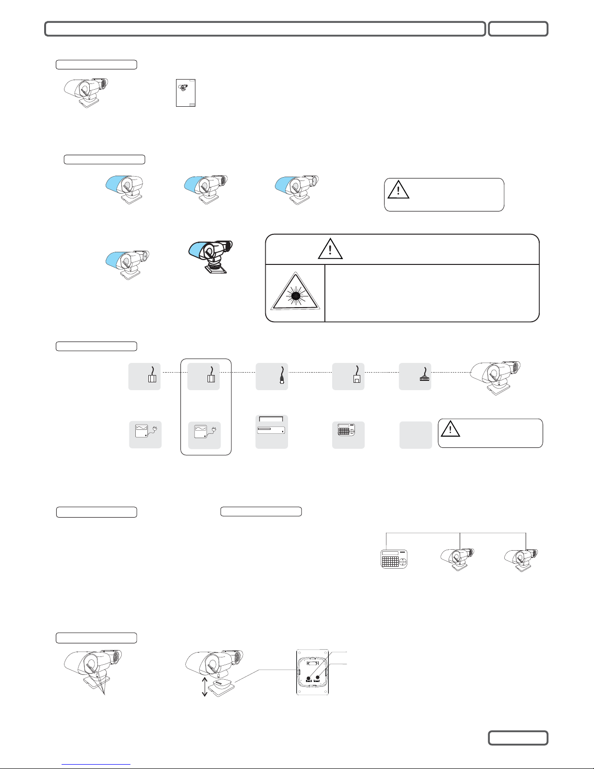
INSTALLATION
English
Keep the original box for
possible transport in the
future.
Switch 1:
Switch 2:
ID Setup
Digit 1 to 5: Protocol setup
Digit 6,7: Baud-Rate
Digit 8: RS485 Termination(default: off)
For setting details, please refer to appendix A.
ID & protocol setup
Step 1
Loose the screws (4 pcs)
and open the base-part
Step 2
Take off the b as e
part for configuration
Step 3
Set th e ID , Proto co l
Baud-Rate and Termination
Sensor
Switch
I/O Interface
Red:AC24V
Black:AC24V
24V AC / 2A
24V
AC
POWER
BNC
VIDEO
RJ-11
RS-485
ALARM
Inner Pin: Video +
Outer Conn.:Video -
Green: RS-485 +
Yellow: RS-485 -
Power
Keyboard
Controller
Monitor
DVR
Connectors
Accessories
Unpacking
Basic Setup
Check-List before installation:
1. Telemetric Protocol setting
2. Dome ID setting
3. Termination setup
3. NecessaryAccessories ( e.g Power
supply)
For telemetric control, make sure that:
1. All devices are set with same protocol
and comm setting.
2. All PTZ devices have an unique ID.
3. Control cable (Rs485) are connected
properly.
For controller setup, please refer to the
operation manual
Example:
Protocol: B02
Baud-Rate: 9600
ID:1
ID:2
Telemetric
1
Model Description
G50
G50IR / G50Q
IR- Headlight
G50VL
Visible Headlight
Do not use Voltage other
than 24VAC,otherweise
will destroy the camera.
Red:AC24V
Black:AC24V
24V AC / 2A
24V
AC
POWER
Power
Addition 24VAC
Power Supply is
require on G50VL
Beamer
G50L
IR-Laser Beam
DANGER
Laser Raidiation Class 3A.
Do not stare into Beam or View
Directly with Optical Instrument
G50M
Mobile Version
with Anti-Shock
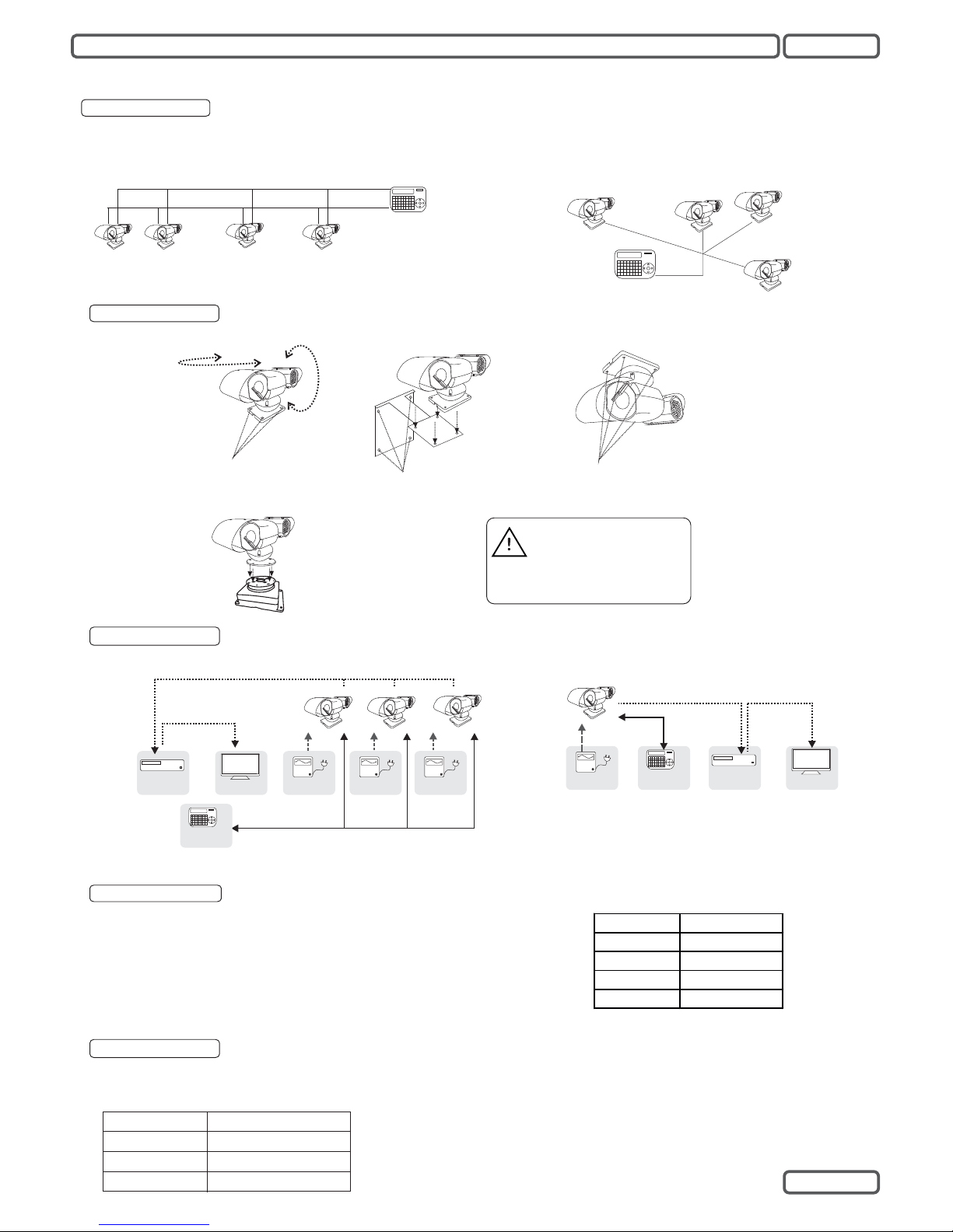
INSTALLATION
Monitor
Keyboard
Controller
DVR
Power
RS-485
Line
Video output
Simple PTZ
RS-485 Daisy-Chain or Star-Form
connection, Termination on the ends.
Video output
Power Power Power
DVR
Monitor
Keyboard
Controller
Multiple PTZ
Application Example
For video signal transmission, coaxial cable with 75 Ohm impedence is recommended. Depends on the cable type, the transmission
distance might be different:
RG 6 /U
Cable standard
RG 11 /U
229m / 750 ft
Max. Distance (m /ft )
305m/ 1000 ft
457m / 1500 ft
RG 59 /U
Video Transmission
The actually transmission distance can vary from the data shown on the table left. It is
necessary to consider the environmental in fluences when planning the installation. If
the transmission requires a larger distance, you may use video-balun or fiber-transmitter
to extend the distance. Contact your local sales representative for further information.
RS485 Transmission
The distance of RS485 transmission between 2 nodes depends on the baudrate. The table on the right side shows the maximum range of every baudrate, assuming a AWG24 wire-pair is used. Note the range might be shorter
than given here, since the cable quality or interferences may affect the
transmitted data, and cause invalid command.
In star-form connection, it might be necessary to use RS-485 Distributor, to
ensure the signal quality of the transmission.
2400 bps
1100m
700m
400m
4800 bps
1700m
9600 bps
19200 bps
Baud Rate
Max. Distance
2
English
Use 4 Screws
to fix (not
included)
Wall-Mount Bracket
(optional accessory)
Reverse-Mount
Use 4 Screws to fix
(not included). Change SETTING in OSD
Mounting
Use 4 Screws to fix
(not included)
360°
Pan
180°
Tilt
Surface-Mount
Wall-Mount
Make sure the installation
enviroment provide enough
space for pan and tilt
movement, else it might
damage the mechanic parts.
For a smooth telemetric operation, it is necessary to set the termination properly.
RS485 Termination
1. Chain Connection
RS 485+
RS 485-
ID:1
Termination
ON
ID:2
Termination
OFF
ID:3
Termination
OFF
ID:4
Termination
OFF
Keyboard
Termination
ON
2. Star-Form Connection
Keyboard
Termination
ON
ID:1
Termination
ON
ID:2
Termination
ON
ID:3
Termination
ON
ID:4
Termination
ON
Mobile-Mount with Anti-Shock
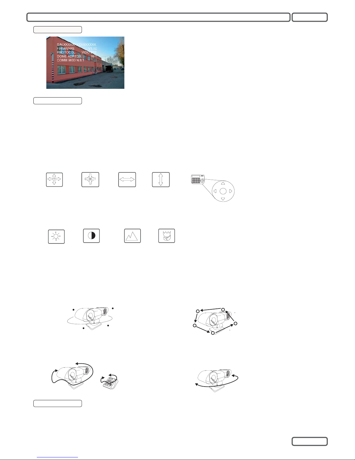
Powering the PTZ
After connected to power source, the PTZ will perform the self-test with pan, tilt and zoom, and
displays the initial screen withfollowing information:
S/N: Serial number of thePTZ
FIRMWARE: Current firmwareversion
PROTOCOL: Protocol version
DOMEADDRESS: the PTZ ID
COMM: Baud-rate and serial settings
The initial screen will disappear once the PTZ camera receives a user command. If the function
“Power up action” is definedwith certain action, itwill execute the action immediately.
OPERATION
Work wit h PT Z
In order to work with the PTZ function, you need a device for telemetric control, such as a controller keyboard, a PTZ software or DVR with PTZ control.
Make sure that the protocol, baud-rate setting are done correctly as described in section “Installation”, or refer to the operation manual of the controller
device.
Beside the pan, tilt and zoom function, this camera provides also auxiliary function for surveillance, such as preset position, self-learning tours and
pattern, which consist the more preset position. The setting of camera and auxiliary function can be accessed either directly from the keyboard, or
through the On-Screen-Display ( OSD)menu, a text-based navigationmenu projected on the monitorscreen.
PAN, TILT and ZOOM Functions
In order to work with the PTZ function, you need a device for telemetric control, such as a controller keyboard, a PTZ software or DVR with PTZ
control. Make sure that yourcontroller device supports thesefunctions.
Zoom in
PAN
Zoom out
TILT
The PAN and TILT function are mostly
performed from the Joystick on the keyboard.
Please refer to the user’s manual of contoller
device for operation instruction
IRIS and FOCUS
IRIS Open
FOCUS
Far
IRIS Close
In regular operation, the focus and iris will be regulated automatically to achieve best image quality. If case of need, you can adjust Iris and focus
setting by press the correspondingbuttons on the controllerdevice. The auto-focuswill resume once a PTZcommand is triggered.
FOCUS
Near
Auxiliary Function
The auxiliary function provides user automated action, such as memorizing position and recalling by a direct input on the cotnroller device. Make
sure that the keyboard controlleryou use support thesefunction, and refer to themanual for operation.
PRESET: A Pan-Tilt position which contains the zoom
setting. Up to 128 presets can be stored in the camera
Preset 1
Preset 2
Preset 4
Preset 3
SEQUENCE(PRESET TOUR): An auto-touring thourgh the defined,
stored preset positions. Each tour can contain up to 24 preset points.
Total 4 tours can be stored in the camera.
Preset 1
Preset 2
Preset 4
Preset 3
Preset X
SCAN TOUR: A Pan-Tilt moving between 2 defined limits. Up to 4 scan
tours are supported
Left Limit
Right Limit
PATTERN TOUR: A recording of user’s Pan, Tilt and
zoom up to 180 seconds. Up to 4 pattern tours are
supported
KB3N
Camera Functions
This PTZ camera provides also image enhancement functions, such as BLC, AGC, AE or the Day/Night Vision. Details will be introducece in the
section “OSD”.
3
English
 Loading...