

Avue ADR87XXXD User Manual

DVR User Manual
For H.264 8/16-channel digital video recorder
All rights reserved

DVR User Manual
CAUTION
Please read this user manual carefully to ensure that you can use the device correctly and
safely.
There may be several technically incorrect places or printing errors in this manual. The
updates will be added into the new version of this manual. The contents of this manual are
subject to change without notice.
This device should be operated only from the type of power source indicated on the
marking label. The voltage of the power must be verified before using. If the device doesn‟t
work for a long time, pull out the plug from the socket.
Do not install this device near any heat sources such as radiators, heat registers, stoves or
other device that produce heat.
Do not install this device near water. Clean only with a dry cloth.
Place the device in a well-ventilated area.
Do not power off the DVR at normal recording condition! The correct operation to shut
off DVR is to stop recording firstly, and then to select “shut-down” button at the right of the
menu bar to exit, and finally to cut off the power.
This machine is indoor using equipment. Do not expose the machine in rain or moist
environment. In case any solid or liquid get into the machine‟s case, please cut off the power
supply immediately, and ask for qualified technicians to check the machine before restart
Do not try to repair the device by yourself without technical aid or approval.
When this product is in use, the relevant contents of Microsoft, Apple and Google will
be involved in. The pictures and screenshots in this manual are only used to explain the
usage of our product. The ownerships of trademarks, logos and other intellectual properties
related to Microsoft, Apple and Google shall belong to the above-mentioned companies.
This manual is suitable for 8/16-channel digital video recorders. All examples and
pictures used in the manual are from 16-channel DVR.

DVR User Manual
Table of Contents
1 Introduction .......................................................................................................................... 1
1.1 DVR Introduction ................................................................................................................ 1
1.2 Main Features ...................................................................................................................... 1
2 Hardware Installation .......................................................................................................... 3
2.1 Install Hard Drive & DVD Writer ....................................................................................... 3
2.1.1 Install Hard Drive ............................................................................................... 3
2.1.2 Install DVD Writer ............................................................................................. 4
2.2 Front Panel Descriptions ...................................................................................................... 5
2.3 Rear Panel Instructions ........................................................................................................ 6
2.4 Remote Controller ............................................................................................................... 6
2.5 Control with Mouse ............................................................................................................. 8
2.5.1 Connect Mouse ................................................................................................ ... 8
2.5.2 Use Mouse .......................................................................................................... 8
3 Basic Function Instruction ................................................................................................. 10
3.1 Power On/Off .................................................................................................................... 10
3.1.1 Power On ................................................................................................ .......... 10
3.1.2 Power Off ......................................................................................................... 10
3.2 Login ................................................................................................................................. 10
3.3 Live Preview ................................................................ ...................................................... 11
3.4 Live Playback .................................................................................................................... 11
4 Main Menu Setup Guide .................................................................................................... 13
4.1 Basic Configuration ........................................................................................................... 14
4.1.1 System .............................................................................................................. 14
4.1.2 Time & Date ..................................................................................................... 15
4.1.3 DST .................................................................................................................. 15
4.2 Live Configuration ............................................................................................................ 16
4.2.1 Live ................................................................................................................... 16
4.2.2 Main Monitor.................................................................................................... 17
4.2.3 Mask ................................................................................................................. 17
4.3 Record Configuration ........................................................................................................ 18
4.3.1 Enable ............................................................................................................... 18
4.3.2 Record Bitrate ................................ ................................ ................................ ... 19
4.3.3 Time .................................................................................................................. 19
4.3.4 Stamp ................................................................................................................ 20
4.3.5 Recycle Record ................................................................................................. 21
4.3.6 Snap ................................ ................................................................ .................. 21
4.4 Schedule Configuration ..................................................................................................... 21
4.4.1 Schedule ........................................................................................................... 21
4.4.2 Motion Schedule ............................................................................................... 22
4.4.3 Sensor Schedule................................................................................................ 23
4.5 Alarm Configuration .......................................................................................................... 23
4.5.1 Sensor Alarm .................................................................................................... 23
4.5.2 Motion Alarm ................................................................................................... 25

DVR User Manual
4.5.3 Video Loss ........................................................................................................ 26
4.5.4 Other Alarm ...................................................................................................... 26
4.5.5 Alarm Out ......................................................................................................... 27
4.6 Network Configuration ...................................................................................................... 28
4.6.1 Network ............................................................................................................ 28
4.6.2 Sub Stream........................................................................................................ 29
4.6.3 Email ................................................................................................................ 29
4.6.4 Server................................................................................................................ 30
4.6.5 Other Settings ................................................................................................... 30
4.7 User Management Configuration ....................................................................................... 33
4.8 P.T.Z Configuration ........................................................................................................... 34
4.9 Advanced ........................................................................................................................... 37
4.9.1 Reset ................................................................................................................. 37
4.9.2 Import/Export ................................................................................................... 38
4.9.3 Block/Allow List .............................................................................................. 38
5 Search, Playback & Backup .............................................................................................. 39
5.1 Time Search ....................................................................................................................... 39
5.2 Event Search ...................................................................................................................... 39
5.3 File Management ............................................................................................................... 40
5.4 Search by Image ................................................................................................................ 41
5.5 Backup ............................................................................................................................... 41
6 Manage DVR ....................................................................................................................... 43
6.1 Check System Information ................................................................................................ 43
6.1.1 System Information .......................................................................................... 43
6.1.2 Event Information ............................................................................................. 43
6.1.3 Log Information................................................................................................ 43
6.1.4 Network Information ........................................................................................ 43
6.1.5 Online Information ........................................................................................... 43
6.1.6 Record Information .......................................................................................... 43
6.2 Manual Alarm ................................................................................................ .................... 43
6.3 Disk Management .............................................................................................................. 43
6.4 Upgrade ................................................................ ............................................................. 44
6.5 Logoff ................................................................................................................................ 44
7 Remote Surveillance ........................................................................................................... 45
7.1 IE Remote Surveillance ..................................................................................................... 45
7.1.1 On LAN ............................................................................................................ 45
7.1.2 On WAN ........................................................................................................... 45
7.2 Remote Surveillance through Apple PC ............................................................................ 46
7.2.1 On LAN ............................................................................................................ 46
7.2.2 On WAN ........................................................................................................... 48
7.3 The Remote Live Preview ................................................................................................. 48
7.4 Remote Playback & Backup .............................................................................................. 50
7.4.1 Remote Playback .............................................................................................. 50
7.4.2 Remote Backup ................................................................................................ 53
7.5 Remote System Configuration ........................................................................................... 53
7.6 Tools .................................................................................................................................. 54

DVR User Manual
7.7 Remote Management ................................................................................................ ......... 54
8 Mobile Surveillance ............................................................................................................ 55
8.1 By Phones with Windows Mobile OS ............................................................................... 55
8.2 By Phones with iPhone OS ................................................................................................ 56
8.3 By Phones with Android OS .............................................................................................. 61
8.4 By Phones with Blackberry OS ......................................................................................... 65
Appendix A FAQ ................................................................................................................. 70
Appendix B Calculate Recording Capacity ...................................................................... 74
Appendix C Compatible Devices ....................................................................................... 75
Appendix D 8-CH DVR Specifications.............................................................................. 76
Appendix E 16-CH DVR Specifications ............................................................................ 77

DVR User Manual
1
1 Introduction
1.1 DVR Introduction
This model DVR (Digital Video Recorder) is designed specially for CCTV system. It adopts
high performance video processing chips and embedded Linux system. Meanwhile, it utilizes
many most advanced technologies, such as standard H.264 with low bit rate, Dual stream,
SATA interface, VGA output mouse supported, IE browser supported with full remote control,
mobile view(by phones), etc., which ensure its powerful functions and high stability. Due to
these distinctive characteristics, it is widely used in banks, telecommunication, transportation,
factories, warehouse, and irrigation and so on.
1.2 Main Features
COMPRESSION FORMAT
Standard H.264 compression with low bit rate and better image quality
LIVE SURVEILLANCE
Support VGA /CVBS/HDMI output
Support 8/16-ch SDI video inputs
Supports channel security by hiding live display
Display the local record state and basic information
Supports USB to make full control
RECORD MEDIA
Supports eight SATA HDDs to record for a longer time without any limitation
BACKUP
Supports USB 2.0 devices to backup
Supports saving recorded files with AVI standard format to a remote computer through
internet
RECORD & PLAYBACK
Record modes: Manual, Schedule, Motion detection and Sensor alarm recording
Supports recycle after HDD full
Resolution, frame rate and picture quality are adjustable
8/16 audio channels available
Three record search modes: time search, event search and image search
8-CH screen playback simultaneously
Supports deleting and locking the recorded files one by one
Supports remote playback in Network Client through LAN or internet
ALARM
4 channel alarm output and 8/16 channel alarm input available
Supports schedule for motion detection and sensor alarm
Supports pre-recording and post recording

DVR User Manual
2
Supports linked channels recording once motion or alarm triggered on certain channel
Supports linked PTZ preset ,auto cruise and track of the corresponding channel
PTZ CONTROL
Supports various PTZ protocols
Supports 128 PTZ presets and 8 auto cruise tracks
Supports remote PTZ control through internet
SECURITY
Customize user right: log search, system setup, two way audio, file management, disk
management, remote login, live view, manual record, playback, PTZ control and remote live
view
Supports 1 administrator and 63 users.
Supports event log recording and checking, events unlimited
NETWORK
Supports TCP/IP, DHCP, PPPoE, DDNS protocol
Supports IE browser to do remote view
Supports setup client connection amount
Supports dual stream. Network stream is adjustable independently to fit the network
bandwidth and environment.
Supports picture snap and color adjustment in remote live
Supports remote time and event search, and channel playback with picture snap
Supports remote PTZ control with preset and auto cruise
Supports remote full menu setup, changing all the DVR parameters remotely
Supports mobile surveillance by smart phones , WinCE, iPhone or Gphone, 3G network
available
Supports CMS to manage multi devices on internet
DVR User Manual
3
2 Hardware Installation
2.1 Install Hard Drive & DVD Writer
2.1.1 Install Hard Drive
Check the unit and the accessories after getting the DVR. Please don‟t power up the unit till
the physical installation is complete.
Notice: 1. This series support eight SATA hard drives. Please use the hard drive the
manufacturers recommend specially for security and safe field.
2. Please calculate HDD capacity according to the recording setting. Please refer to
“Appendix B Calculate Recording Capacity”.
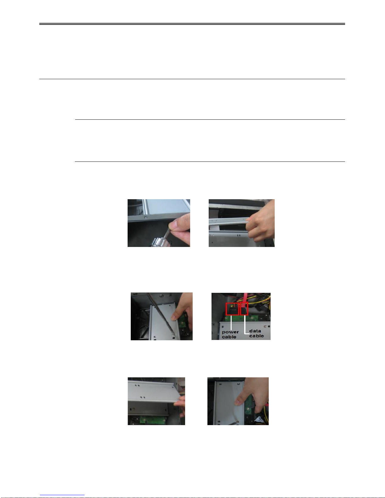
Step 1: Unscrew and open the case and then unscrew the screws in the both sides to take out
of the upper iron bar as shown below:
Step 2: Put the HDD under the lower iron bar and let the screw holes of the HDD aim at the
iron bars‟. Then screw firmly and connect the power and data cables. The pictures are
shown as follows:
Step 3: Install other three HDD according to above-mentioned method. Then cover the
upper iron bar and screw it firmly. Put the HDD under it and screw firmly as shown below:
Step 4: Install other three HDD under the upper iron bar as shown below:
DVR User Manual
4
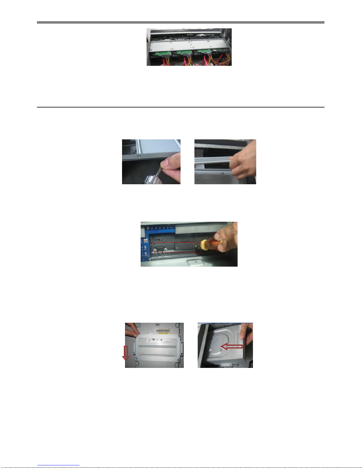
Step 5: Cover the back cover of the device and screw firmly.
2.1.2 Install DVD Writer
Step 1: Unscrew and open the case and then unscrew the screws in the both sides to take out
of the upper iron bar as shown below:
Step 2: Unscrew the four screws in the back of the front panel as shown below and then take
out of the brace with a triangular mark.
Step 3: Install the DVD holder attached with the device. Please let the screw holes of the DVD
aim at the holder‟s. Try to place the holder farther away from the front and then screw firmly.
Then, put the DVD with the holder into the case and let the screw holes of the case aim at the
holder‟s. Next, screw them firmly.
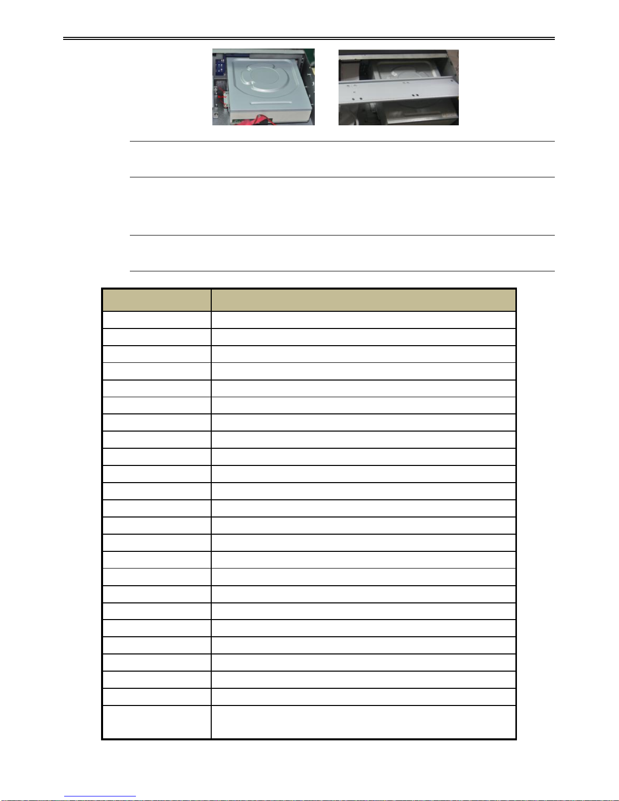
Step 4: Connect the power and data cables and install the upper iron bar. Then, screw firmly
with screws in the both sides.
DVR User Manual
5
Note: If the user installs a DVD, he can only install 4 HDD disks. Because too much
room has been taken up.
2.2 Front Panel Descriptions
Notice: The front panel descriptions are only for reference; please make the object as
the standard.
Name
Description
Power
Switch off-to stop DVR. Use it before turning off the power.
1-10(digital button)
Input number 1-10 or choose channel.
0_ _(digital button)
Input number 0 and the above number together for channels 11to 16
Direction button
Change direction to select items
Enter button
Confirm selection
Backup
The light turns blue when backing up files and data.
Network
The light turns blue when it is able to access the network.
HDD
The light turns blue when reading/writing HDD.
REC
The light turns blue when recording
Playback
The light turns blue when playing video.
MENU button
Enter menu in live
BACKUP button
Enter backup mode in live
Info button
Check recording data
Search button
Enter into search mode
P.T.Z. button
Enter PTZ mode in live
Audio button
Enable the audio in live
REC button
Record manually
Play/Pause button
Play or pause the record
REW button
Rewind key
FF button
Fast forward
Exit button
Exit the current interface or status
Screen mode button
Choose single, four or multiple channel modes
IR
For remote controller
USB port
To connect external USB devices like USB flash, USB HDD for
backup or update firmware; or connect to USB mouse
DVR User Manual
6
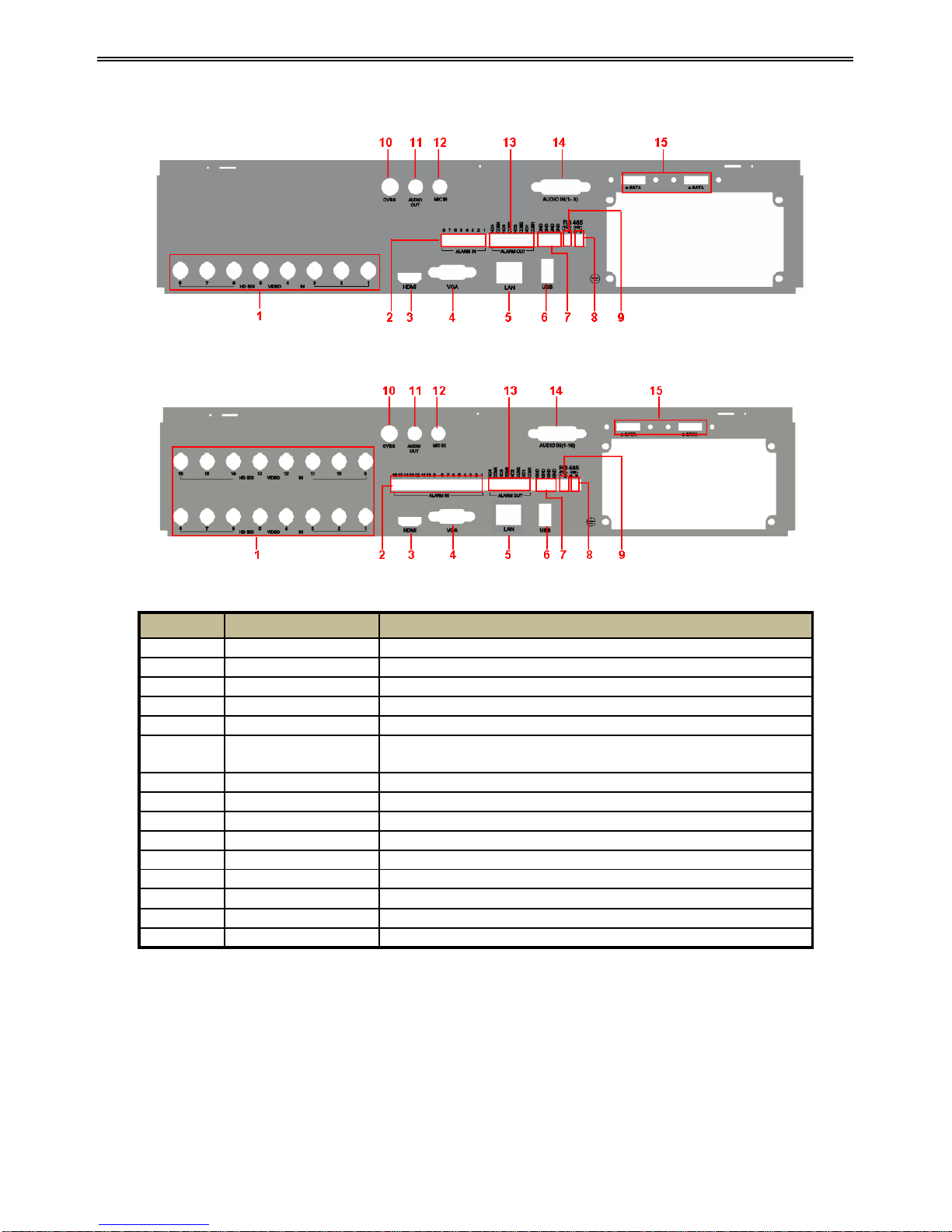
2.3 Rear Panel Instructions
Fig 2-1 Rear Panel for 8-ch
Fig 2-2 Rear Panel for 16-ch
Item
Name
Description
1
HD SD Video in
HD SDI video signal inputs.
2
Alarm in
Alarm Inputs for connecting sensors
3
HDMI port
Connect to high-definition display device
4
VGA port
VGA output, connect to monitor
5
LAN
Network port
6
USB port
To connect external USB devices like USB flash drive, USB
HDD for backup or updating firmware.
7
GND
Grounding
8
K/B
Connect to keyboard. A is TX+, B is TX-.
9
P/Z
Connect to speed dome. Y is TX+, Z is TX-.
10
CVBS
CVBS output
11
Audio out
Audio output, connect to the sound box
12
MIC in
Talk. Connect to microphone
13
Alarm out
Relay Output. Connect to external alarm.
14
Audio in
Audio input
15
E-SATA
Connect to HDD for backup.
2.4 Remote Controller
It uses two AAA size batteries.
Step 1: Open the battery cover of the remote controller.
Step 2: Place batteries. Please take care the polarity (+ and -).
Step 3: Replace the battery cover.
DVR User Manual
7
If it still doesn't work, please change a new remote controller to try, or contact your dealers.
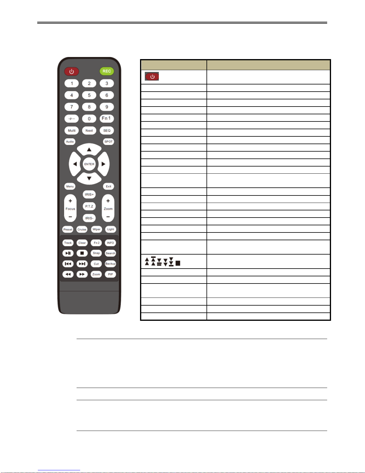
The interface of remote controller is shown in Fig 2-3 Remote Controller.
Fig 2-3 Remote Controller
Key points to check in case the remote doesn’t work.
1. Check batteries polarity.
2. Check the remaining charge in the batteries.
3. Check IR controller sensor for any masking.
4. Check the ID of the remote with respect to the DVR.
Note: You shall press P.T.Z button to enter into PTZ setting mode, choose a channel
and press P.T.Z button again to hide the P.T.Z control panel. Then you can press preset,
cruise, track, wiper or light button to enable the relevant function.
Button
Function
Power Button
Switch off—to stop DVR. Use it before turning
off the power
Record Button
To record manually
-/-- /0-9 Digital Button
Input number or choose camera
Fn1 Button
Unavailable temporarily
Multi Button
To choose multi screen display mode
Next Button
To switch the live image
SEQ
To enter into auto dwell mode
Audio
To enable audio output in live mode
Switch
To switch the output between BNC and VGA
Direction button
To move cursor in setup or pan/title PTZ
Enter Button
To confirm the choice or setup
Menu Button
To enter into menu
Exit Button
To exit the current interface
Focus/IRIS/Zoom/PTZ
To control PTZ camera. Move
camera/zoom/IRIS/Focus
Preset Button
To enter into preset setting in PTZ mode
Cruise Button
To enter into cruise setting in PTZ mode
Track Button
To enter into track setting in PTZ mode
Wiper Button
To enable wiper function in PTZ mode
Light Button
To enable light function in PTZ mode
Clear Button
To return to the previous interface
Fn2 Button
Unavailable temporarily
Info Button
Get information about DVR like firmware
version, HDD information
To control playback. Play/Pause/Stop/Previous
Section/Next Section/Rewind/Fast Forward
Snap Button
To take snapshots manually
Search Button
To enter into search mode
Cut Button
To set the start/end time for backup in playback
mode
Backup Button
To enter into backup mode
Zoom Button
To zoom in the images
PIP Button
To enter into picture in picture setting mode

DVR User Manual
8
Operation processes with remote controller to control multi-DVR
The device ID of the DVR is 0. It‟s not necessary to reset the device ID when a remote is not
be used to control a single DVR. However when controlling multiple DVRs with multiple
remote controllers, you would need to configure the device ID. Please refer to below steps:
Step 1: Activate remote controller to control DVR: Turn the IR sensor of the remote controller
towards the IR receiver on the front panel, press the number key 8 twice, then input device ID
of the DVR to be controlled (Range from: 0-65535; the default device ID is 0) and then
press ENTER button to confirm.
Step 2: Check the device ID of DVR from System Setup Basic Device ID. You can also
set multiple DVRs with the same device ID. However, this can cause interference if the DVRs
are kept close to each other.
2.5 Control with Mouse
2.5.1 Connect Mouse
It supports USB mouse through the ports on the rear panel.
If mouse is not detected or doesn't work, check below steps:
1. Make sure the mouse is plugged in the USB mouse port.
2. Try with a good know mouse.
2.5.2 Use Mouse
During live:
Double-click on any camera window to see the full screen. Double-click again to return to the
previous screen.
Right click to reveal the control menu on the screen. Right click again to hide the menu.
In Configuration:
Click to enter a particular option. Right click to cancel the option or to return to the previous
menu.
In order to input a value in a particular screen, move cursor to the input box and click. An
input window will appear as Fig 2-4. It supports digits, alphabets and symbols input. Click
Shift button to input Capital letters and symbols; click Shift button again to return.
It supports mouse drag. Take setting up motion detection area for example: Click customized,
hold down the left button and drag to set motion detection area.

DVR User Manual
9
Fig 2-4 Digital Numbers and Letters Input Window
In Playback:
Click to choose the options. Right click to return to live mode.
In Backup:
Click to choose the options. Right click to return to previous picture.
In PTZ Control:
Click left button to choose the buttons to control the PTZ. Click right button to return to live.
Note: Mouse is the default tool for all operations unless an exception, as indicated.

DVR User Manual
10
3 Basic Function Instruction
3.1 Power On/Off
Before you power on the unit, please make sure all the connection is good.
3.1.1 Power On
Step 1: Connect with the source power.
Step 2: The device will boot and the power LED would turn blue.
Step 3: A WIZZARD window will pop up and show some information about time zone, time
setup, network configuration, record configuration and disk management. User can setup here
and refer to the concrete setup steps from the corresponding chapters. If users don‟t want to
setup Wizard, please click Exit button to exit.
Note: This DVR can only display options on either VGA/HDMI monitor or BNC
monitor at a given point of time, if there is live image display without menu options
then please check if there is display on other device/monitor, or long press Exit key to
wait for login dialog box to appear. Long press Exit key can switch the output
between BNC and VGA/HDMI.
3.1.2 Power Off
User can power off the device by using remote controller, keyboard and mouse.
By remote controller:
Step 1: Press Power button. This will take you to a Shut down window. The unit will power
off after a while by clicking OK button.
Step 2: Disconnect the power
By keyboard and mouse:
Step 1: Enter into Menu and then select “Shut Down” icon to pop up the Shut down
window.
Step 2: Click OK. Then the unit will power off after a while.
Step 3: Disconnect the power.
3.2 Login
User can login or log off the DVR system. Once logged off the user cannot do any other
operation except changing the multi-screen display.
DVR User Manual
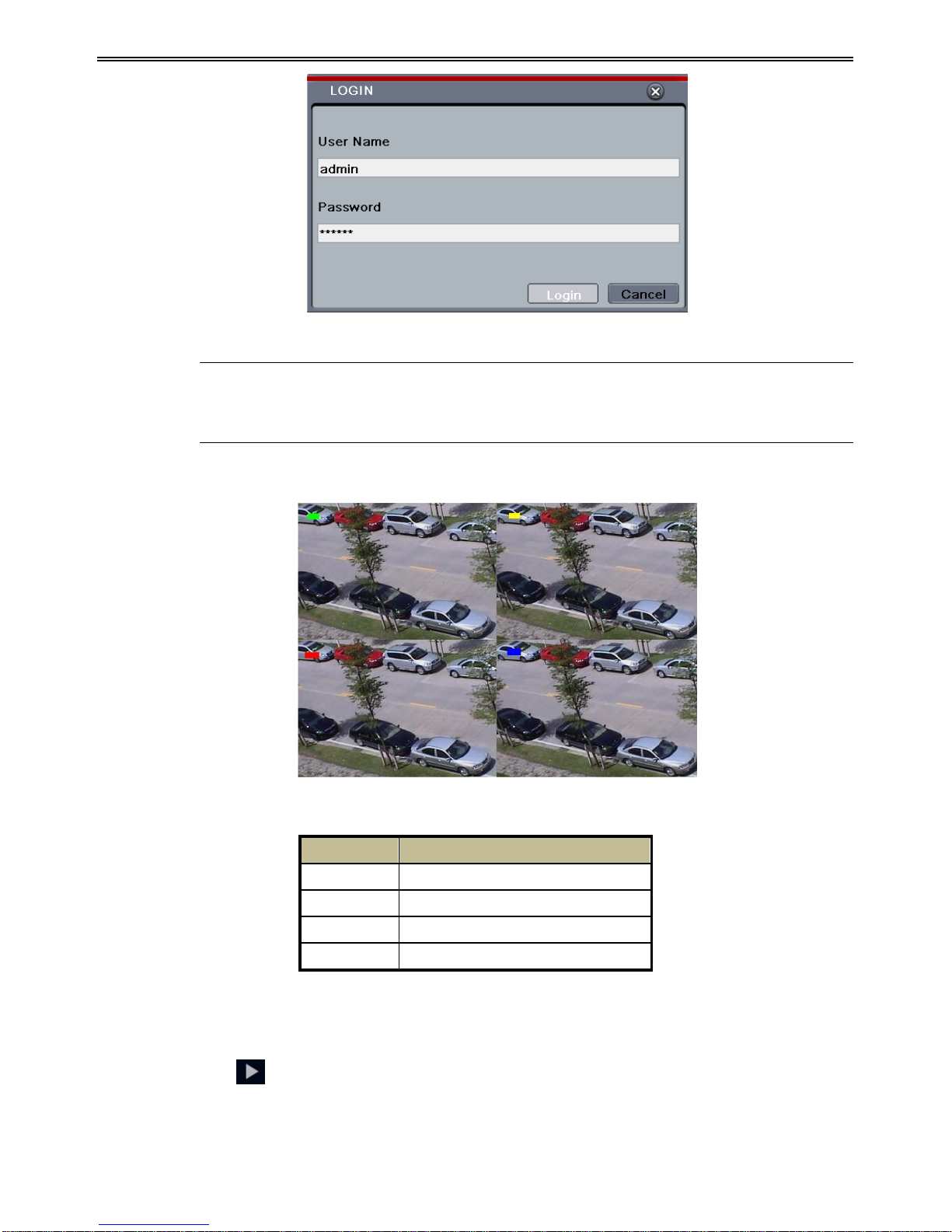
11
Fig 3-1 Login
Notice: The default user name and password is “admin” and 123456”.
For complete operational steps for changing password, adding or deleting users,
please refer to section 4.7 User Management Configuration.
3.3 Live Preview
Fig 3-2 Live Preview Interface
3.4 Live Playback
Click Play button to playback the record. Refer to Fig 3-3. User can do complete
operation by clicking the buttons on screen.
Symbol
Meaning
Green
Manual record
Yellow
Motion detection record
Red
Sensor Alarm record
Blue
Schedule record
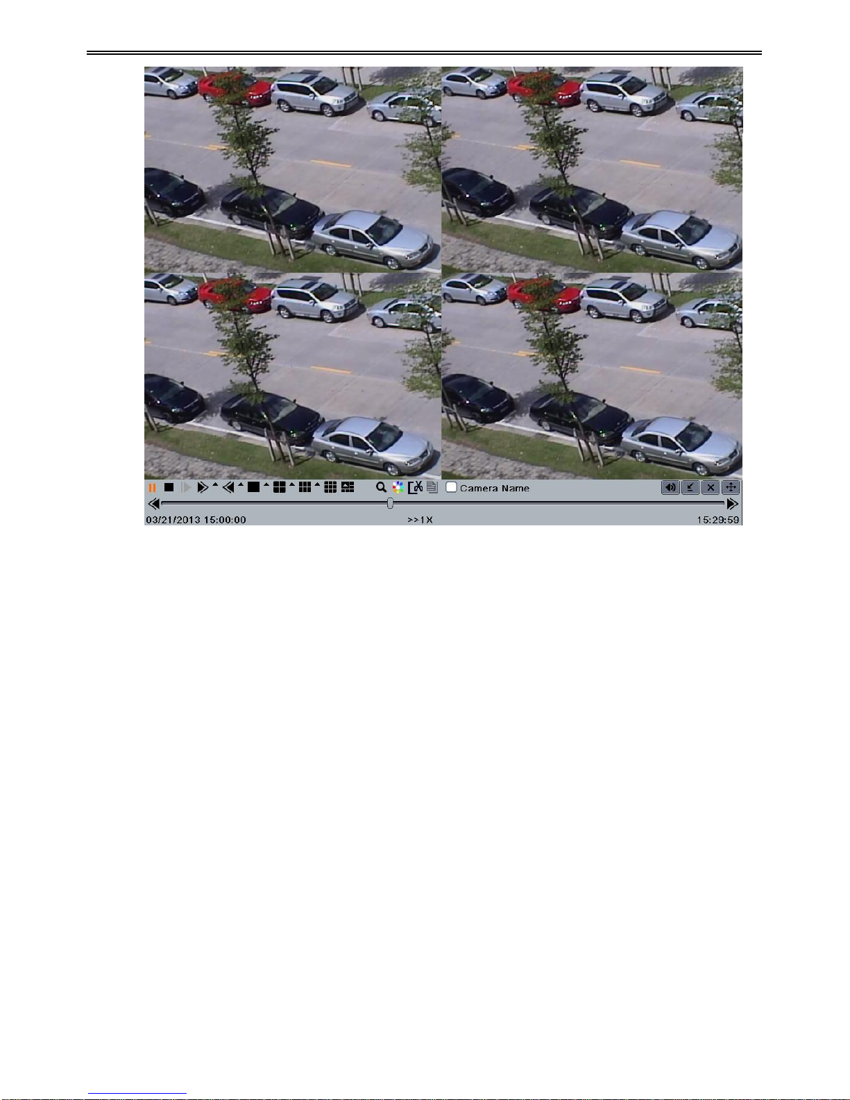
DVR User Manual
12
Fig 3-3 Live Playback

DVR User Manual
13
4 Main Menu Setup Guide
Click right mouse or press EXIT button on the front panel and then the control bar will display
at the bottom of the screen. Refer to Fig 4-1:
Fig 4-1 Main Menu Toolbar
Single: Choose a channel from the list to be displayed in the full screen mode.
Multi: Choose the display mode for viewing multiple channels.
Dwell: Dwell means to display live images from different cameras in a sequence. The images
may be displayed as a single channel or in a grid fashion from different cameras. Dwell mode
is enabled only when the chosen display mode is not able to display all the available cameras.
E-Zoom: Single channel large screen electronic amplification.
Audio: Enable sound.
PTZ: Click the PTZ button to control rotation position, speed and auto scan of the PTZ.
Snap: Click this button to snap the live pictures. These pictures will automatically be saved in
the SATA disk.
Record: Click this button to start/stop recording.
Playback: Click this button to playback the record files.
Click Menu button to pop up a window as Fig 4-2. You can also press MENU button on
the front panel or operate with remote controller to display the main menu. Clicking Setup
icon will pop-up the configuration menu:
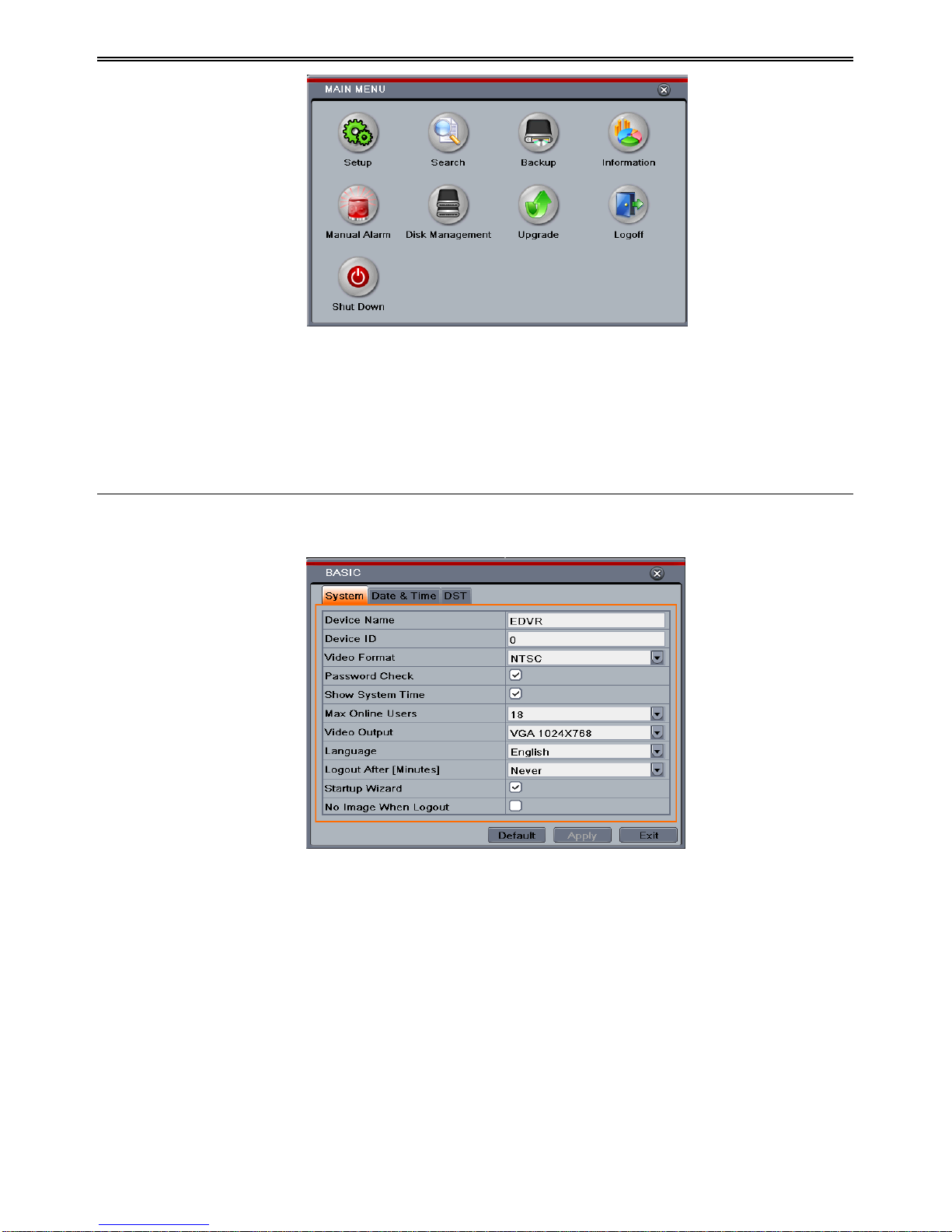
DVR User Manual
14
Fig 4-2 Setup
4.1 Basic Configuration
Basic configuration includes three sub menus: system, date & time and DST.
4.1.1 System
Step 1: Enter into MenuSetupBasic System interface. Refer to Fig 4-3:
Fig 4-3 Basic Configuration-System
Step 2: In this interface you can setup the device name, device ID, video format, max network
users, VGA resolution, language and so on. The definitions for every parameters display as
below:
Device Name: The name of the device. It may display on the client end or CMS that help user
to recognize the device remotely.
Device ID: This ID is used to map the DVR with IR remote controller and speed dome
cameras.
Video Format: Two modes: PAL and NTSC. User can select the video format according to
that of camera.
Password Check: If this option is enabled, the user would need to input the user name and the
DVR User Manual
15
password for performing corresponding operations.
Show System Time: If selected, the current time will be displayed during live monitoring.
Max Online Users: To set the max number of concurrent user logins in the DVR.
Video Output: The resolution of live display interface, range from: VGA800*600,
VGA1280*1024 and HDMI.
Note: Switching between VGA and HDMI will change the menu output mode. Please
connect to relevant monitor.
Language: Setup the menu language.
Note: After changing the language and video output, the device needs to login again.
Logout After (Minutes): A user can setup the screen interval time (30s, 60s, 180s, 300s). If
there is no any operation within the setting period, the device will auto logout and return to
login interface.
Show Wizard: If selected, the GUI would launch the startup wizard on every boot, allowing
the user to do basic setup.
No Image When Logout: If selected, there will be no image showing when logging out.
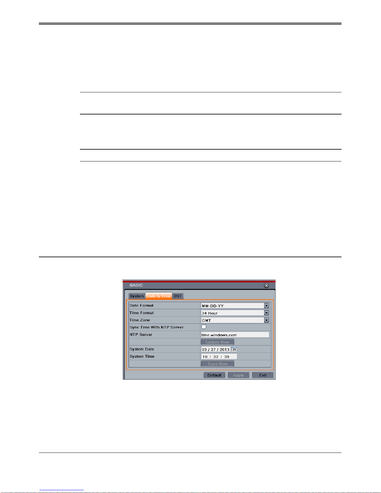
4.1.2 Time & Date
Step 1: Enter into MenuSetupBasic Date & Time interface. Refer to Fig 4-4:
Fig 4-4 Basic Configuration-Date & Time
Step 2: Set the date format, time format, time zone in this interface; checkmark “sync time
with NTP server” to refresh NTP server date. You can also adjust system date manually.
Step 3: Click “Apply” button to save the setting.
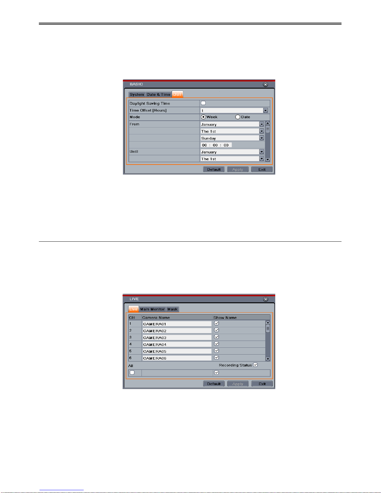
4.1.3 DST
DVR User Manual
16
Step 1: Enter into MenuSetupBasic DST interface. Refer to Fig 4-5:
Step 2: In this interface, enable daylight saving time, time offset, mode, start & end
month/week/date, etc.
Step 3: Click “Apply” button to save the setting.
Fig 4-5 Basic Configuration-DST
4.2 Live Configuration
Live configuration includes three submenus: live, main monitor and mask.
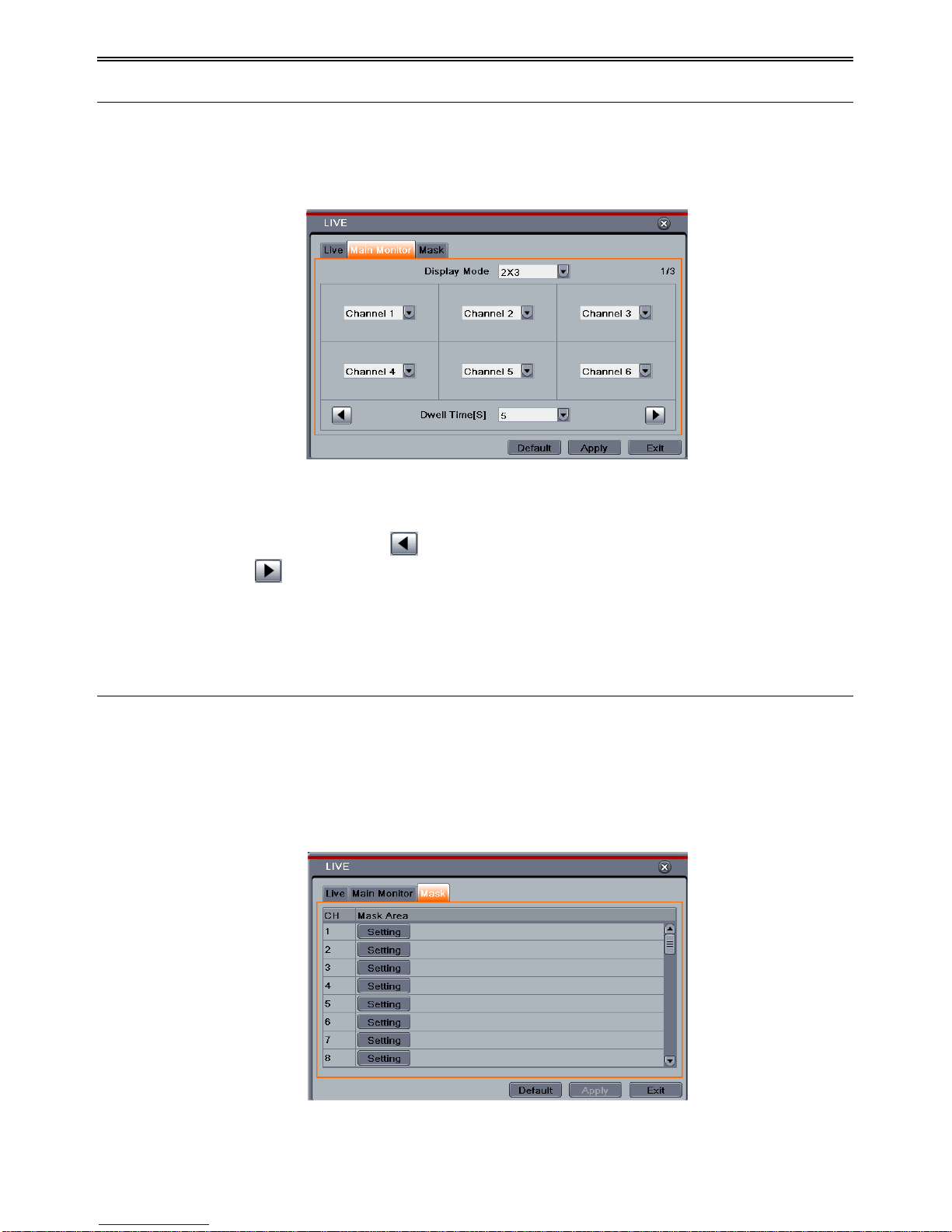
4.2.1 Live
In this interface, you can setup camera name and adjust colors.
To setup camera name:
Step 1: Enter into MenuSetupLive. Refer to Fig 4-6:
Fig 4-6 Live ConfigurationLive
Step 2: A software keyboard will pop up by clicking camera name area. Click the letters and
(or) digital numbers on the keyboard to input the name you want to display in live image.
Step 3: Checkmark the camera name in the show name area.
All channels will show the camera name by checking “All” checkbox.
Step 4: Click “Apply” to save the setting.
DVR User Manual
17
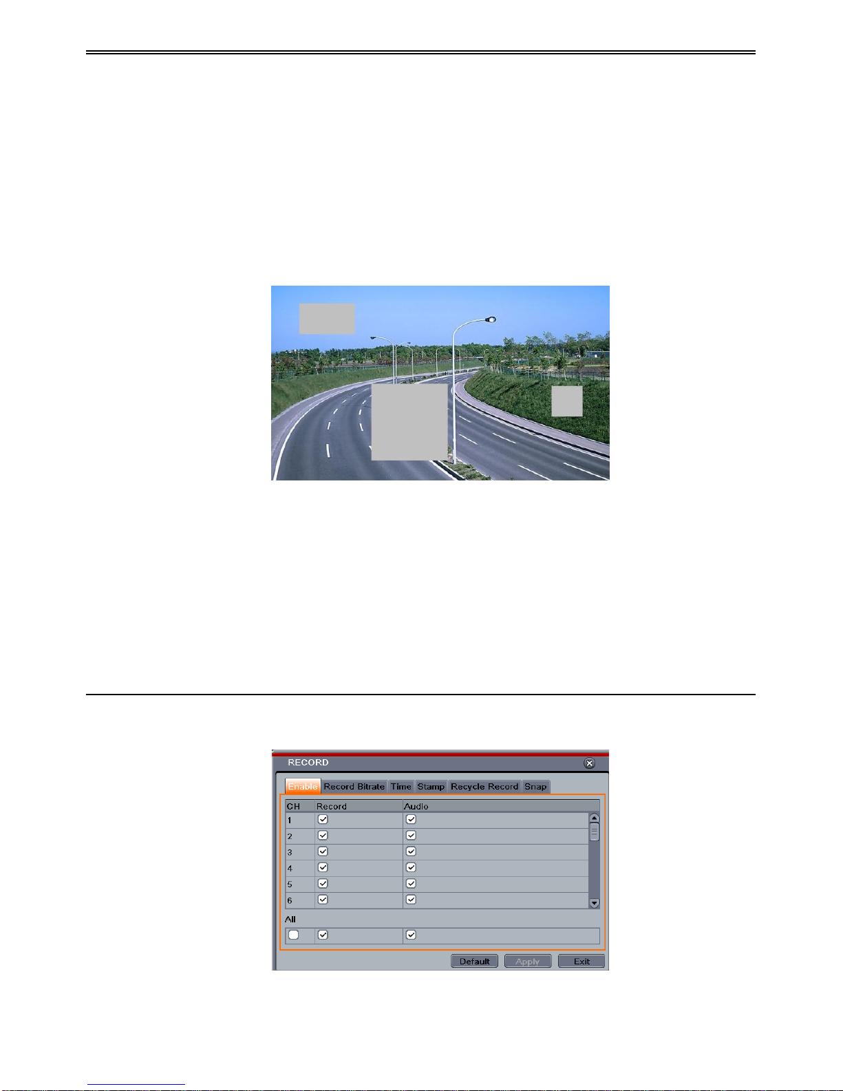
4.2.2 Main Monitor
The main monitor settings allow you to set camera sequence in live display mode.
Operate the following steps to set main monitor:
Step 1: Enter into MenuSetupLive Main Monitor interface. Refer to Fig 4-7:
Fig 4-7 Live Configuration-Main Monitor
Step 2: Select display mode and channel.
Step 3: Select dwell time. Click button to setup the previous channel groups of dwell
picture. Click button to set the latter channel groups of dwell picture.
Step 4: Click “Apply” to save the setting.
4.2.3 Mask
If there is something you don‟t want to display in the live image. You can set mask. For a
given channel a maximum of three areas can be masked.
To setup mask area:
Step 1: Enter into MenuSetupLive Mask interface.
Fig 4-8 Live Configuration-Mask
DVR User Manual
18
Step 2: Click Setting button to go into live image.
Step 3: Press and drag the left mouse button to set mask area as shown below.
Step 4: Right click to exit the mask setting interface.
Step 5: Click Apply button to save the setting.
To delete mask area
Step 1: Click Setting button in the mask interface.
Step 2: Select a certain masked area and double click to delete that masked area.
Step 3: Then click Apply button to save the setting.
Fig 4-9 Setup Mask Area
4.3 Record Configuration
Record configuration includes six sub menus: enable, record bit rate, time, recycle record,
stamp and snap.
Before Configuration, please make sure your DVR has been installed with HDD and has
completed its initialization.
4.3.1 Enable
Step 1: Enter into MenuSetupRecordEnable interface. Refer to Fig 4-10:
Fig 4-10 Record Configuration-Enable
DVR User Manual
19
Step 2: Checkmark record and audio.
Step 3: Select All to setup the same settings for all channels.
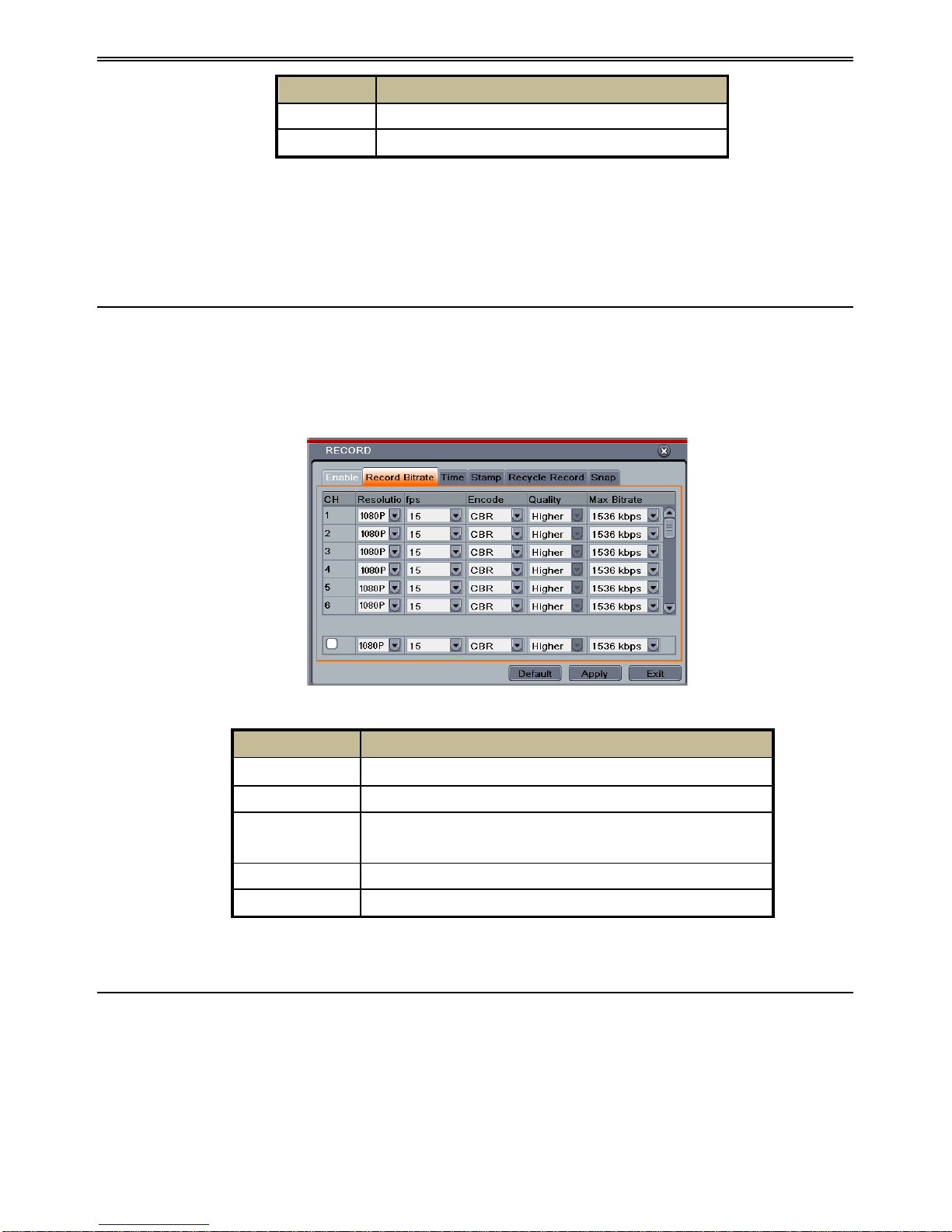
4.3.2 Record Bitrate
Step 1: Enter into MenuSetupRecord Record Bitrate. Refer to Fig 4-11:
Step 2: Setup rate, resolution, quality, encode and max bit stream.
Step 3: Select “All” to set the same settings for all channels.
Step 4: Click “Apply” button to save the setting.
Fig 4-11 Record Configuration-Record Bitrate
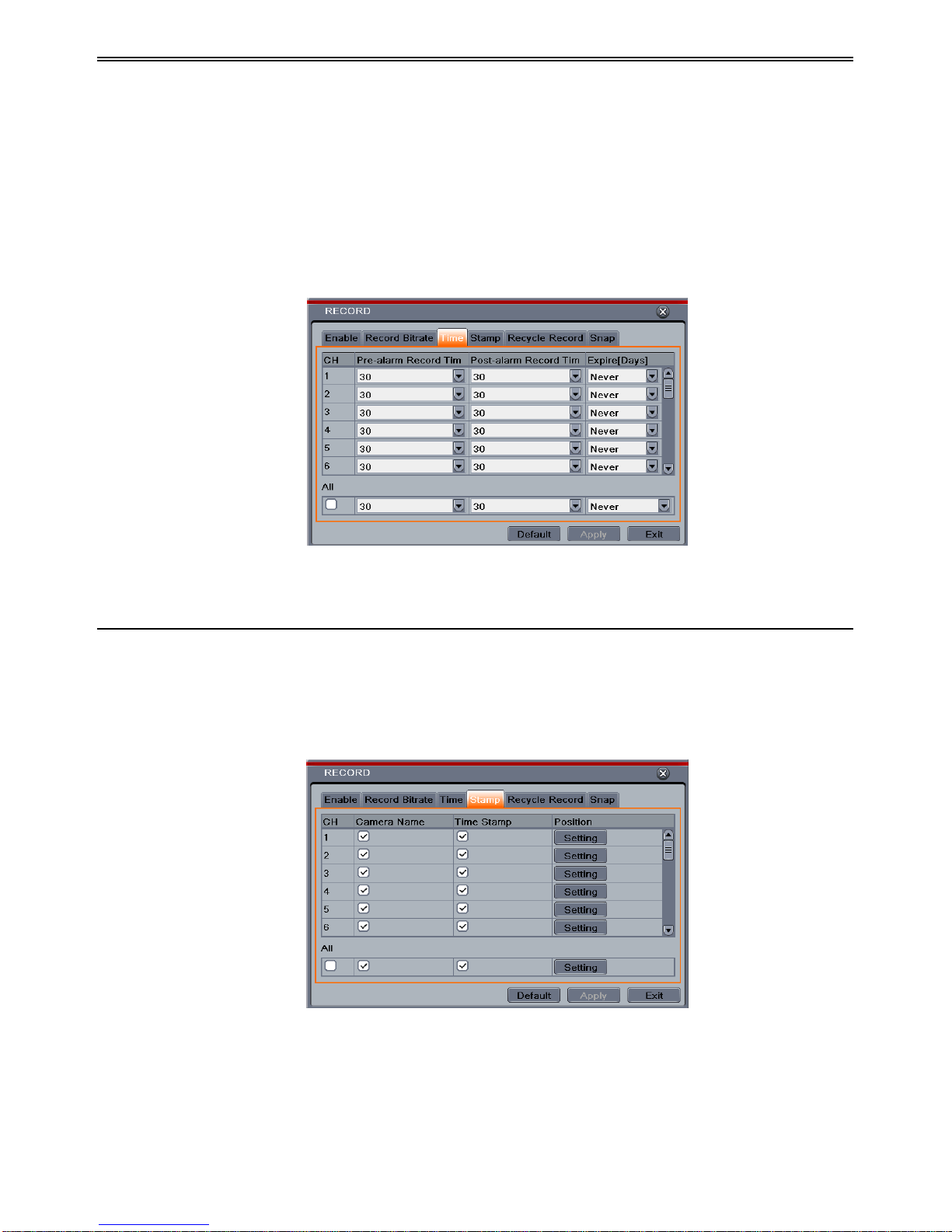
4.3.3 Time
Step 1: Enter into MenuSetupRecord Time interface to set recording time. Refer to Fig
4-12:
Step 2: Set Pre-alarm record time and post-alarm record time. Select “All” to set the same
settings for all channels.
Parameter
Meaning
Record
To enable/disable recording for the channel
Audio
To enable/disable audio recording for the channel
Parameter
Meaning
Rate
Range from: 1-15(NTSC)1-12(PAL)
Resolution
Supports 1080P.
Quality
The higher the value is, the clearer the recorded image is. Six
options: lowest, lower, low, medium, higher and highest.
Encode
VBR and CBR
Max bit stream
Range from: 1536kbps~12288kbps
DVR User Manual
20
Pre-alarm Record Time: Set the time in seconds to pre-record before the actual recording
begins.
Post-alarm Record Time: Set the time in seconds to post-record after the actual recording
has finished, five options: 10s, 15s, 20s, 30s, 60s, 120s, 180s and 300s.
Expire Time: Set the expiration time for recorded video. If the set date is overdue, the
recorded files will be deleted automatically.
Step 3: Click “Apply” to save the setting.
Fig 4-12 Record Configuration-Time
4.3.4 Stamp
This provides an option to enable or disable the Camera Name and the Time stamp on the
video. The user can also choose a position for the stamp on the screen.
To setup stamp as follows:
Step 1: Enter into Menu SetupRecordStamp interface. Refer to Fig 4-13:
Fig 4-13 Record Configuration-Stamp
Step 2: Checkmark camera name and time stamp. Click Setting button to setup the position of
the stamp. You can drag the camera name and time stamp at random positions. Refer to below
Figures:
 Loading...