

Page 1
INDUSTRIAL AUTOMATION, INC.
8 9 01 E. P LE A SA N T VA L LE Y R O A D
I N DE P EN D EN C E, OH I O 4 41 3 1- 5 50 8
T E L E P H O N E : ( 1 ) 2 16 - 64 2 -1 2 30
E - M A I L : t ac h s@ a vt r on . co m
•
F A X : (1 ) 2 1 6- 6 42 - 60 3 7
•
W E B : ww w . av tr o ne n co d er s .c om
Encoder
Instructions
M6-1 and M6-2
Inactive Design
Contact Help Desk
EXPLOSION PROTECTED, SOLID SHAFT
DESCRIPTION
The Avtron Model M6-1 and M6-2 are Solid Shaft Incremental
Encoders (also known as tachometers or rotary pulse generators).
They are similar to the model M4 Heavy Mill Duty rotary solid
shaft incremental encoder but utilize flameproof and increased
safety construction. The M6 compliance with the Essential Health
and Safety Requirements has been assured by compliance with
EN60079-0, EN60079-1 and EN60079-7 (Certificate of Conformity
No. DEMKO 02 ATEX 131477X) The M6 is certified for use in CAT
2 (Zone 1) Gas Group IIC potentially explosive atmospheres when
marked with the code II 2G Ex de IIC T4 (Tamb -20°C to +80°C).
Tamb -40°C also available (Special modification 001).
Mechanically, the M6-1 mounts on a NEMA 56C adapter flange.
The M6-2 can be foot mounted by using an optional foot mounting
bracket kit. When coupled to a motor or machine, the M6 output is
directly proportional to shaft position (pulse count) or speed (pulse
rate). The M6 can be used for both control and instrumentation
applications.
The enclosures on all Model M6s are rated IP 66 to protect the
internal components from the entry of dust and liquids. The M6
uses magnetoresistive sensing technology, making the M6 ideal
for demanding industrial environments.
All M6s can be equipped with one or two outputs. Each output is
electrically independent and totally isolated.
The outputs can be wired as single ended single phase,
single ended two phase (A,B), or differential (A Quad B).
Output resolution is determined by the rotor’s base PPR (pulses
per revolution), times a sensor multiplier. The sensor module can
provide: 1/2 the base PPR, the base PPR, or double the base PPR
(see table). With two outputs, the same encoder can provide two
different PPRs from a given rotor at the same time. Only one rotor
per encoder is possible.
Example: an M6 could use a 1024 PPR sensor output on one side
for feedback to a drive system, and simultaneously use a 256 PPR
sensor on the other side for a process computer.
AVAILABLE RESOLUTIONS
-48 OPTION -51 OPTION -60 OPTION
LOW
MEDIUM
HIGH
240 256 300
480 512 600
960 1024 1200
M6 ENVIRONMENT
The M6 does not produce flammable gasses or dusts in normal
operating modes. The M6 does not cause injury or harm when
used in conjunction with the installation guide. The M6 does not
produce ignition capable electrical sparks or arcs and has been
designed not to produce potential ignition sources from electromagnetic, acoustic, optical or other energy sources. The M6 is not
considered as a safety device and is not suitable for connection
into a safety system.
The installer should refer to the latest edition of the following standards before installing or operating in a Hazardous Area:
EN 1127-1 Explosive Atmospheres - Explosion prevention and
protection, basic concepts, and methodology.
EN 60079-14 Electrical apparatus for explosive gas at mospheres - Part 14: Electrical installations in hazardous areas
(other than mines).
The M6 housing and shaft materials are listed in the spe cifications.
These materials are not considered as able to trigger an explosion
in normal operating modes and various fault modes in accordance
with the requirements for Cat 2 equip ment. These materials are not
known to react with any explosive atmo spheres to which the M6
may be subject. It is however the responsibility of the end user to
ensure that the M6 is selected correctly for the potentially explosive atmosphere in which the equipment is to be put into service.
INSTALLATION
Equipment needed for installation
Supplied:
1. M6 Encoder
2. Anti-Seize Compound (copper)
Not Supplied:
Socket Hd. Cap Screw 5/16" Hex Wrench (T-Handle style)
3/8-16 x 0.75 (4) Shaft Coupling
Washer, Flat 5/16 (4) Motor Adapter Flange
Washer, Lock 5/16 (4) Dial Indicator
Thread Locker (Loctite 242 recommended)
Optional:
Foot Bracket Mounting Kit (A28380)
Armoured Cable Gland
Clean machine shaft of any dirt and check for any burrs or
damage.
M6 PART NUMBERS AND AVAILABLE OPTIONS
Model
M6-
Mounting
Style
0-
Non-Standard
1- Face mount
5/8" x 2" shaft
2- Foot mount
5/8" x 2.64"
(2" net) shaft
Shaft Style Line Driver
S-
Single
Ended Shaft
Left & Right
Output Range
1-
5 to 24 VDC
2-
5 to 18 VDC
3-
12 to 24 VDC*
* Units shipped prior to 2009 were rated 18 to 24 volts. Refer to ID tag on the encoder for specific input voltage requirements.
X-
None
L-
Low Range
(Base PPR x 1/2)
M-
Medium Range
(Base PPR x 1)
H-
High Range
(Base PPR x 2)
Base
485160-
PPR
480
512
600
Marker Connector Modifications
Z- Marker
– - None
T-
Conduit Box,
Terminal Block,
3/4" NPT
W-
Conduit Box,
Terminal Block
and Wire Gland
000-
None
001- Low Temp (-40°C)
Page 2
The encoder must be driven by a positive drive rather than a
friction drive. The following means of coupling are acceptable
when properly installed: Direct Coupling, Timing Belt/Pulleys,
Chain/Sprockets.
With a direct drive, use a flexible coupling and align the shafts as
accurately as possible. Example: For a size 62 Thomas Miniature
Coupling, angular misalignment must be less than 1.34°, parallel
misalignment less than 0.028", and axial float less than ± 0.031".
Overhung loads should also be minimized. Installations using
timing belts/pulleys should have just enough belt tension to
eliminate belt sag. Excessive tension will shorten belt and bearing
service life. Refer to the specifications for maximum bearing load
ratings. If a rubber slinger disc is used, position it on the shaft so
it will rotate freely.
CAUTION
Do not force or drive the coupling onto the shaft or
damage to the bearings may result. The coupling
should slide easily on the shaft. Remove nicks and
burrs if necessary. Consider driving shaft endplay
when positioning coupling.
For more details on alignment specifications, measure ment
techniques, and special considerations in specifying and installing
drive components, refer to separate installation instructions in
the Avtron PULSE GENERATOR HANDBOOK.
NEMA 56C FACE MOUNTING INSTRUCTIONS
1) Apply anti-seize compound to inner circumference of coupling
(both motor and encoder side).
2) Loosen set screws in coupling and apply thread locker to set
screws.
3) Place coupling on motor shaft, inserting to depth per
manufacturer’s instructions.
4) Attach coupling to motor shaft using set screws per
manufacturer’s instructions.
5) Bolt mounting flange (flowerpot) to motor C-Face, using
thread locker with fasteners.
6) Slide encoder shaft into other side of coupling. DO NOT
FORCE. Ensure 1/4" keyway aligns with coupling set screw
location.
7) Ensure C-Face on mounting flange matches and aligns with
encoder C-Face precisely.
SPECIFICATIONS
ELECTRICAL
A. Operating Power (Vin)
1. Volts ............................ See Line Driver Options
2. Current ........................ 120mA, no load
B. Output Format
1. 2O/ & Comp (A,A–, B,B–)
2. Marker......................... 1/Rev (Z,Z–)
C. Signal Type ...................... Incremental, Square Wave, 50 ±10% Duty Cycle
D. Direction Sensing ............O/ A leads O/ B for CW rotation as viewed
....................................from the back of the tach looking at the
....................................non-drive end of the motor.
E. Transition Sep. ................. 15% minimum
F. Frequency Range ............ 0 to 150,000 Hz.
G. PPR ................................. 240, 256, 300, 480, 512, 600, 960, 1024, 1200
H. See Line Driver Options
MECHANICAL
A. Shaft Inertia ..................... 0.1 Oz. In. Sec.2 Typical
B. Acceleration..................... 5,000 RPM/Sec. Maximum
C. Starting Torque ................2.0 Oz. In. (Typical)
D. Speed ................................5,000 RPM Max.
E. Weight .............................16 lbs. maximum
F. Shaft Diameter
Tolerance ....................See drawing on page 4.
G. Shaft Engagement ..........See drawing on page 4.
H. Bearing Protection: Shaft seal & double bearing seal.
I. Bearing Life with No Additional Loading: 6.1 x 10⁹ Revolutions
J. Maximum Additional Bearing Load:
1. -1 (5/8"): 5 pounds axial or 20 pounds radial
2. -4 & -5 (1" & 1 1/8"): 10 pounds axial or 30 pounds radial
3. -6 (2"): 25 pounds axial or 75 pounds radial
4. -7 (2 3/8"): 30 pounds axial or 90 pounds radial
K. Shaft Material: Black Oxide treated steel.
L. Housing Material: Cast aluminum with Polane S Plus polyurethane
enamel finish.
* Units shipped prior to 2009 were rated 18 to 24 volts. Refer to ID tag on the encoder for specific input voltage requirements.
8) Apply thread locker to hex cap screws.
9) Align bolt holes of encoder and flange, thread in (4) hex cap
screws, using lock washers.
10) Tighten set screws on encoder side of coupling.
FOOT MOUNTING INSTRUCTIONS
Equipment needed for installation
Supplied:
1. Foot Bracket (A28380) 4. Nut, Hex 5/16-18 (4)
2. Soc. Hd. Cap Screw 5. Washer, Flat 5/16 (4)
3/8-16 x .75 (4) 6. Washer, Lock 5/16 (4)
3. Hex Hd. Cap Screw 7. Thread Locker (blue)
5/16-18 x 1.50 (4)
Not Supplied:
1/2" Wrench
5/16" Hex Wrench (T-Handle style)
Dial Indicator
The optional foot mounting bracket kit is Avtron P/N A28380.
Read all of the following instructions and the Avtron PULSE GENERATOR HANDBOOK prior to beginning any work.
The M6 performance and life will be directly affected by the
installation. Following this sequence of steps is recommended.
1) The foot mounting bracket must be secured to a flat, rigid,
vibration free steel or aluminum base which can be machined
to accept 5/16-18 mounting hardware. See next section.
2) Temporarily mount the M6 to the foot bracket, install the
coupling to the M6 and driver and verify that the location is
suitable for installation.
3) If the M6 encoder, bracket, and coupling are suited to the area,
check motor/encoder shaft alignment with a straight edge from
multiple positions around the shaft circumference to verify that
it meets specifications.
4) While maintaining alignment, precisely mark the position of the
foot bracket on its mounting base.
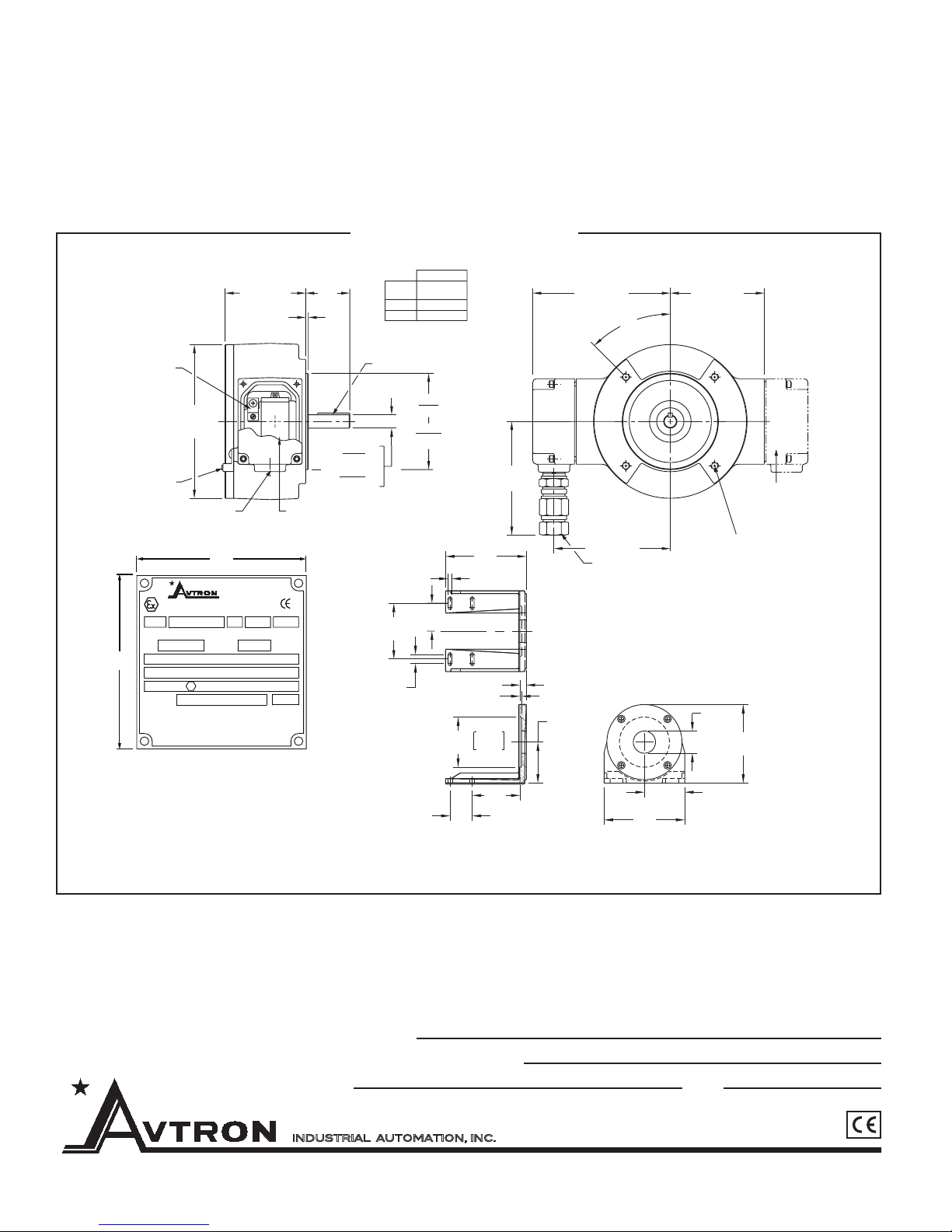
5) Remove the M6. Transfer punch or layout the mounting hole
pattern as indicated on outline drawing.
6) Machine four, 3/8" diameter through holes or tap four, 5/16-18"
holes in center of base slots to give some degree of freedom
in final alignment.
7) Reinstall the M6 with the flexible coupling loosely in place, and
ENVIRONMENTAL
A. Enclosure Rating: IP66
B. Operating Temperature:
C. Hazardous Locations: Ex de IIC T4 (Tamb -20°C to +80°C Standard, -40°C
to +80°C Optional use Modification “001”)
OUTPUT TERMINATIONS
Terminal Block: EEx e II compression type. Accepts AWG 14 (2.08mm2) to AWG
20 (.52mm
cable gland available (maximum ambient temperature with gland +60°C allowing
for 20°C rise in housing.)
2
) stranded wire. Housing available with 3/4 NPT or optional armored
LINE DRIVER OPTIONS
Voltage Input (Vin)
Output High (Volts)
Output High
(milliamps)
Output Low (Volts)
Output Low
(milliamps)
Protection
Maximum Cable
Drive(Feet)
80C° to -40°C (-40°C optional, -20°C standard)
Output Options
1 2 3*
5-24 VDC 5-18 VDC 12-24 VDC
(Vin) -2 (typ) (Vin) -1 (typ) 330 ohm pull up
80 (max.) 80 (avg.),1500 (peak) 330 ohm pull up
0.5 (typ) 0.5 (typ) 1 (max.)
80 (max.) 80 (avg.),1500 (peak) 50 (avg.)
Reverse Voltage,
Transient,
Short Circuit
(high & low)
1000 ft. @ 5 V
500 ft. @ 12 V
200 ft. @ 24 V
Reverse Voltage,
Transient,
Short Circuit (none)
2000 ft. 1000 ft.
Reverse Voltage,
Transient,
Short Circuit (low)
Page 3
tighten down all mounting hardware. Check motor/encoder
shaft alignment with a straight edge from multiple positions
around the shaft circumference to verify that it meets
specifications. Use thread locker supplied on cap screws which
mount M6 to foot bracket.
8) Ensure any flat or keyway on the motor and encoder shaft are
aligned with the set screw holes of the flexible coupling. Apply
thread locker to coupling set screws and tighten per
manufacturer’s recommendations.
9) Recheck alignment and tighten all hardware after first several
hours of operation.
MINIMIZE DOWNTIME: Should M6 replacement be required,
leave the foot mounting bracket installed on its base and mount
the new M6 to the bracket. This maintains the original alignment.
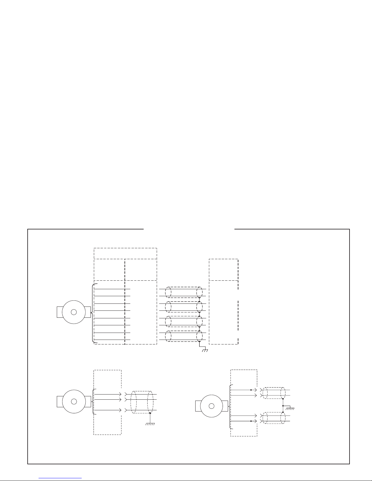
WIRING INSTRUCTIONS
The M6 can be wired for single phase, two-phase, with or without
complements, with or without markers. See wiring diagrams on the
following page.
CAUTION
Do not wire the M6 Encoder while energized. Doing so
may damage the encoder, and/or cause risk of fire or
explosion.
For bidirectional operation of the encoder, proper phasing of the
two output channels is important. Phase A channel leads phase B
channel for clockwise shaft rotation as viewed from the anti-drive
or accessory end of the motor (M6 mounting end).
CORRECTIVE ACTION FOR PHASE REVERSAL
1) Remove Power.
2) Exchange wires on cable, either at encoder cable end, or at
speed controller end (but not both).
a) Single Ended 2 Phase Wiring (see wiring diagram)
Exchange A and B at the use end of the wires.
b) Differential 2 Phase Wiring (see wiring diagram)
Exchange either A with A– in the phase A pair OR B with B
in the phase B pair but NOT both.
3) Apply Power.
4) Verify encoder feedback is correct, using hand rotation of
shaft, or jog mode of the speed controller.
Refer to the system drawing for specific cable requirements where
applicable.
Physical properties of cable such as abrasion, tensile strength,
solvents, marine applications, etc., are dictated by the specific
appli cation. Requirements for hazardous locations are dictated
by the rele vant codes. General electrical requirements are:
stranded copper, 20 AWG (.52mm2) through 14 AWG (2.08mm2),
each wire pair individually shielded with braid or foil with drain
wire, 0.05 uF maximum total mutual or direct capacitance, outer
sheath insulator, 2,000 ft. max. (See line driver specifications).
Temperature ratings of wire and wire glands should be 20°C over
the maximum expected ambient or motor temperature to allow for
temperature rise in the encoder itself.
MAINTENANCE
CAUTION
Do not open the M6 housing. Doing so will void the
warranty and may cause the risk of fire or explosion.
–
WIRING DIAGRAMS
DIFFERENTIAL APPLICATIONS
SIGNAL CODE
OPTION
“T” & “W”
BLACK
RED
GREEN
YELLOW
BLUE
GRAY
ORANGE
WHITE
SINGLE ENDED
SINGLE PHASE APPLICATIONS
OUTPUT
BOX
BLACK
RED
GREEN
1
2
3
4
5
6
7
8
1
2
3
COMMON
+5 TO +24 VOLTS
SIGNAL
GROUND
*(SEE LINE DRIVER OPTIONS)
*
REF
SIGNAL
COM
+V
+5 TO +24 VOLTS
ØA
–
ØA
ØB
–
ØB
Z
= MARKER
–
Z
*
*(SEE LINE DRIVER OPTIONS)
SINGLE ENDED
TWO PHASE APPLICATIONS
OUTPUT
BOX
RED
BLUE
GREEN
BLACK
2
5
3
1
*(SEE LINE DRIVER OPTIONS)
+5 TO +24 VOLTS*
ØB
GROUND
ØA
COMMON
TYPICAL WIRE:
18 AWG (.82mm
2
), multiple pair, individually shielded.
NOTE: Avtron standard warranty applies.
Copies available upon request.
Specifications subject to change without notice.
Page 4
2.75
There are no field replaceable parts in an M6. The unit should be
returned to the factory for all repairs.
Build up of large amounts of contamination are to be avoided,
therefore periodic cleaning is recommended.
The condition of the bearings is important to the safety of the
explosion-proof housing. The bearing manufacturer’s rated life
OUTLINE DRAWING
(see specifications) can be adversely affected by application
specific conditions. If the unit shows signs of bearing wear
indicated by noise or degradation of the electrical signal output, it
should be returned to the factory for repair.
DIM
AA
1
2.06 [52.33]
2 2.64 [67.06]
4.500
DIA
4.497
[114.300]
DIA
[114.224]
2.51
[63.75]
4.505
Ø
4.502
2.00
[50.80]
7.25
[184.15]
0.33 [8.38]
0.15 [3.81]
114.427
114.350
4.28
[108.71]
5.32
[135.13]
6.44 [163.63]
45∞
5.44 [138.23]
OPTION “W”
TERMINAL BLOCK
WITH ARMOURED CABLE GLAND
NOTE: CABLE GLAND Tamb (-60∞C to +80∞C)
MUST BE DERATED FOR
TEMPERATURE RISE IN ENCODER.
OPTIONAL FOOT BRACKET
INCLUDES ALL HARDWARE NECESSARY
FOR MOUNTING PULSE GENERATOR AND
0.58 [14.73]
3.685
[93.60 ]
FOOT BRACKET TO MACHINE BASE.
FOR USE WITH SHAFT OPTION 2
+0.000
-0.030
+.0
-.76
7.25
[184.15]
3.62
[92.08]
4.40 [111.76]
OPTIONAL
2nd OUTPUT
(REMOVE BLANKING ELEMENT
TO UTILIZE OPTIONAL 2nd OUTPUT)
3/8-16 UNC-2B THREAD
4 HOLES EQUALLY SPACED
ON A 5.875 [149.225] DIA B.C.
SEE NOTE 3
Ø2.00
[50.80]
7.06
[179.32]
OPTION “T”
TERMINAL BLOCK
0539
IP66
AA
SHAFT OPTION 2 IS FOR USE
WITH OPTIONAL FOOT BRACKET
SHOWN BELOW
3/16 (4.763) SQ KEY (FURNISHED)
0.6250
DIA
0.6245
[15.8750]
DIA
[15.8623]
3.77 [95.88]
0.12 [3.05]
INTERNAL
GROUNDING LUG
7.19
[182.63]
DIA
EXTERNAL
GROUNDING LUG
3/4" NPT
B31661
PULSE GENERATOR
Date Mfg
Type Option Code
Imax= 160mA, Pmax= 4.48W Ea Output
2.81
Ex de IIC T4 (Tamb to +80˚C)
CE 0539
DEMKO 02 ATEX 131477X
Cert No.
WARNING: DO NOT OPEN IN A FLAMMABLE
ATMOSPHERE OR WHEN ENERGIZED
Tamb -20°C to +80°C standard, optional Tamb -40°C to +80°C available with
special option codes 001.
Rev
Ser.No.
PPR
II 2G
Ex
VDC
5 – IDENTIFICATION LABEL: SEE ABOVE
4 – DIMENSIONS IN PARENTHESIS ARE MILLIMETERS
3 – PILOT MOUNTING CONFORMS TO A NEMA 56C FACE
2 – ALL DIMENSIONS ARE APPROX.
SHAFT
OPTION
5.02
[127.51]
0.82
[20.83]
1 – WEIGHT: 16 LBS. MAX.
NOTES:
* “VDC” to be “5-18” or “5-24” or “12-24”
Avtron standard warranty applies. All dimensions are in inches (mm) approx.
Features and specifications subject to change without notice.
EU DECLARATION OF CONFORMITY: The Model M6 Encoder has been assessed and type tested against the following Harmonized
European Standards: EN 50081-1:1992, EN 50082-1:1998. The Model M6 has been found to be compliant with the requirements of EU
Directive 89/336/EEC provided that the following conditions are met: The electrical supply to the M6 must be within specified limits. The
electrical supply must offer suitable protection from voltage surges unless the application does not require such protection. On behalf of Avtron:
Stephen L D’Henin, Certification Manager, Epsilon Certification Service.
INDUSTRIAL AUTOMATION, INC.
8901 E. PLEASANT VALLEY RD., INDEPENDENCE, OH 44131, U.S.A. • (216) 642-1230 • FAX (216) 642-6037 • www.avtronencoders.com
These instructions have been reviewed and the product evaluated as suitable for our application.
Company Name
Authorized Company Representative
Title Date
REV: 11-09-10
 Loading...