

Page 1

Application Note
111128.02
Device ManageR
Sierra Wireless AirLink GL6110
Instructions For Connecting The AirLink GL6110 GSM Modem w/USB
To Your PC And Conguring It For Use With Device ManageR
e AirLink GL6110 GSM Modem w/USB Connect oers immediate connectivity of AVTECH’s Room Alert and
TemPageR monitors to any GSM / GPRS network. Follow the instructions below for easy and immediate installation and
conguration of the AirLink GL6110 modem on your PC, for use with AVTECH’s Device ManageR application soware.
Step 1: Setting Up The AirLink GL6110 GSM Modem w/USB
1. Open the SIM card holder and insert your SIM card into the SIM card socket on the
front of the AirLink GL6110 GSM Modem. The SIM card should slide easily into the
holder (see gure A). Push the SIM card all the way in until you hear a clicking sound.
Once the SIM card is in place, close the SIM card holder. (To extract the SIM card,
simply push the SIM card until you hear a clicking sound. The SIM card should spring
out of the socket and can then safely be removed from the holder).
2. Connect the included FME Antenna to the RF connector on the back of the AirLink
GL6110 GSM Modem (see gure B). Make sure that the antenna is securely fastened.
3. Connect the Micro-t USB cable into the 8-Pin Micro-Fit connector on the back of the
modem (see gure C). This cable provides the USB connection and is used as the power
source for the GL6110.
CAUTION: Make sure that you are using the cable that was supplied with your AirLink GL6110 modem. Using a different
8-Pin Micro-t cable or interchanging cables between modems may damage either the modem or the PC.
Step 2: Connecting The AirLink GL6110 GSM Modem w/USB To Your PC
1. Go to the ‘Downloads’ section on the AVTECH website (AVTECH.com/Downloads). Login using the Username
and Password emailed to you when you purchased your Room Alert or TemPageR monitor. Click to download
the GSM Plugin (purchased separately) onto the host PC that is running AVTECH’s Device ManageR application
software. Follow the download instructions as prompted.
A - SIM
B - Antenna
C - USB
2. Connect the USB end of the Micro-t cable into the USB port on the PC running Device ManageR.
AVTECH Software • Phone 401.628.1600 • Sales 888.220.6700 • Support 401.628.1650 • Web AVTECH.com
Page 2

3. Once the GSM Plugin is installed and the modem is connected, conrm which COM port the modem is being found
on. To do this, navigate to the System Properties screen on the host PC by clicking on the: ‘Start Menu’ –> ‘Control
Panel’ –> ‘System’ –> ‘System Properties’.
Device Manager (Windows ‘Control Panel’ –> ‘System Properties’ –> ‘Hardware’)
System Properties (Windows Control Panel)
4.
Once you have navigated to ‘System Properties’, click on the ‘Hardware’ tab, then on the ‘Device Manager’ button.
Here you will nd the devices installed and connected to the host PC.
5. Once the ‘Device Manager’ screen is opened, expand the ‘Modems’ selection and select the correct modem (Sierra
Wireless Device) from the list of modem devices displayed.
6. Right click and select the ‘Properties’ tab and then the ‘Modem’ tab. Here, the properties for the AirLink GL6110
GSM modem will display and there you should see the COM port that the modem is set to use.
Device Properties (Sierra Wireless Modem)
AVTECH Software • Phone 401.628.1600 • Sales 888.220.6700 • Support 401.628.1650 • Web AVTECH.com
Page 3
7. Open AVTECH’s ‘Device ManageR’ application software. Click on the ‘Settings’ tab towards the bottom of the left
menu. Here you nd the ‘External Modems’ option. Click ‘External Modems’ and continue to Step 3: Conguring
The AirLink GL6110 GSM Modem w/USB.
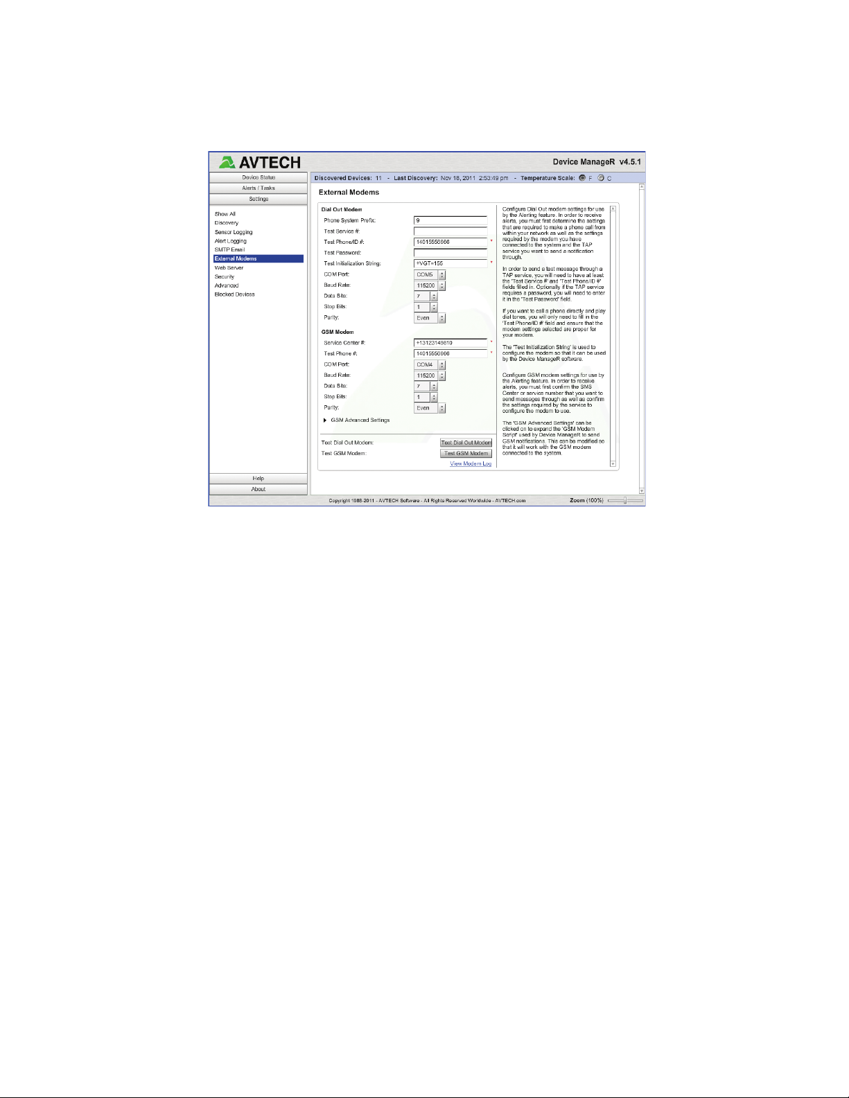
AVTECH’s Device ManageR (ADM) Application Software (‘Settings’ –> ‘External Settings’)
Step 3: Conguring The AirLink GL6110 GSM Modem w/USB
NOTE: The above screen shows the default settings AVTECH recommends for use with the AirLink GL6110 GSM Modem
w/USB. This is NOT the default settings you will see when rst opening the ‘External Modems’ section of the ‘Settings’
screen. The COM port is unique to each installation of a modem and will therefore have to be re-set. Most GSM modems will
want to use the following settings:
Baud Rate: 115200 Data Bits: 7 Stop Bits: 1 Parity: Even
1. Once the ‘GSM Modem’ section of the ‘External Modems’ settings of Device ManageR has been congured to
the settings required by your GSM modem and the service provider used for your SIM card, you can test your
conguration by clicking the ‘Test GSM Modem’ button. This will send a test message to the number dened in the
‘Test Phone #’ eld (‘GSM Modem’ settings). The ‘GSM Advanced Settings’ (near the bottom left of the screen) can
be clicked to expand the ‘GSM Modem Script’ used by Device ManageR to send notications. This can be modied
so that it will work with the GSM modem connected to the host PC.
2. Test your GSM modem now. Once you have received the text alert notication, as expected, you can then go on to
create a GSM action object which will be used to send SMS notications when alerts occur. To create a GSM action
you will need to navigate to the ‘Alerts / Tasks’ section of Device ManageR. Click the ‘Actions’ tab, then ‘Add’ to
congure this new action. Once the ‘Add New Action’ dialog box appears, click on the ‘Action Type’ drop down
and select ‘Send Via GSM’.
AVTECH Software • Phone 401.628.1600 • Sales 888.220.6700 • Support 401.628.1650 • Web AVTECH.com
Page 4

ADM - Add New ‘Action’ (Choosing A Name)
ADM - Add New ‘Contact’ (Dening GSM Phone Settings)
Make sure to give the action a name that is unique, and accurately depicts what the action is used for. For example, the
user in this case chose the name ‘SMS Notify Joe’, as the SMS notication is going to be sent to the contact Joe. The
‘Contact’ selected is ‘Joe - Work Phone’ which has already been congured in the ‘Alerts / Tasks’ –> ‘Contacts’ –>
‘Add’ –> ‘Phone #’ eld under the ‘GSM (SMS) Settings’ section of the ‘Add New Contact’ dialog box seen below.
3. Enter a message in the ‘Message’ eld of the ‘Add New Action’ dialog box. This message is used in the body
of the notication. Messages are limited to 85 characters and can be customized to contain value data and alert
‘keywords’. For example a keyword such as [CURRENT_VALUE] will send the value data of the sensor that was
triggered at the time the notication was sent. This is useful for continued alerts to know the severity of the alert
as it continues and when the issue is resolved. A list of the Device ManageR keywords can be viewed in the ‘Insert
Keyword’ dialog box by simply clicking inside the ‘Message’ eld, as shown in the screen shot below.
ADM - Add New ‘Action’ (Messages - Click To Insert Keyword)
ADM - Sample Keywords
4. Your AirLink GL6110 modem is now congured. Test to make sure it is congured correctly by clicking the
test button at the bottom of the ‘Add New Action’ screen. This should take less than a minute, depending on
your service provider. If the alert notication is not received, verify your settings and try again. If assistance
is needed, contact AVTECH’s Technical Support.
AVTECH Software • Phone 401.628.1600 • Sales 888.220.6700 • Support 401.628.1650 • Web AVTECH.com
 Loading...