

Page 1

A V T E C H E L E C T R O S Y S T E M S L T D .
X
N A N O S E C O N D W A V E F O R M E L E C T R O N I C S
S I N C E 1 9 7 5
1
P.O. BOX 265
OGDENSBURG, NY
U.S.A. 13669-0265
TE L: 888-670-8 729 ( USA & Ca nada) or +1-61 3-6 86 -6675 (Int l)
FAX: 800-561-1 970 ( US A & Canada) or +1-61 3-686-6679 (Intl)
info@avtechpulse .com - http ://www.avtechpulse.com/
INSTRUCTIONS
MODEL AV-110D-PS
BOX 5120, LCD MERIVALE
OTTAWA, ONTARIO
CANADA K2C 3H5
0 to ±30V, 1 MHz
VARIABLE-GAIN
LINEAR AMPLIFIER
SERIAL NUMBER: ____________
Page 2

WARRANTY
Avtech Electrosystems Ltd. warrants products of its manufacture to be free from
defects in material and workmanship under conditions of normal use. If, within
one year after delivery to the original owner, and after prepaid return by the
original owner, this Avtech product is found to be defective, Avtech shall at its
option repair or replace said defective item. This warranty does not apply to
units which have been dissembled, modified or subjected to conditions
exceeding the applicable specifications or ratings. This warranty is the extent of
the obligation assumed by Avtech with respect to this product and no other
warranty or guarantee is either expressed or implied.
2
TECHNICAL SUPPORT
Phone: 888-670-8729 (USA & Canada) or +1-613-686-6675 (International)
Fax: 800-561-1970 (USA & Canada) or +1-613-686-6679 (International)
E-mail: info@avtechpulse.com
World Wide Web: http://www.avtechpulse.com
Page 3

TABLE OF CONTENTS
WARRANTY......................................................................................................................2
TECHNICAL SUPPORT....................................................................................................2
TABLE OF CONTENTS....................................................................................................3
INTRODUCTION...............................................................................................................5
AVAILABLE OPTIONS............................................................................................................ 5
SPECIFICATIONS.............................................................................................................6
REGULATORY NOTES.....................................................................................................7
FCC PART 18.......................................................................................................................... 7
EC DECLARATION OF CONFORMITY...................................................................................7
DIRECTIVE 2002/95/EC (RoHS)............................................................................................. 8
DIRECTIVE 2002/96/EC (WEEE)............................................................................................8
AC POWER SUPPLY REGULATORY NOTES........................................................................9
INSTALLATION...............................................................................................................10
3
VISUAL CHECK.................................................................................................................... 10
POWER RATINGS................................................................................................................. 10
CONNECTION TO THE POWER SUPPLY............................................................................ 10
PROTECTION FROM ELECTRIC SHOCK............................................................................11
ENVIRONMENTAL CONDITIONS.........................................................................................12
FUSES.............................................................................................................................13
AC FUSE REPLACEMENT...................................................................................................13
DC FUSE REPLACEMENT...................................................................................................14
FUSE RATINGS..................................................................................................................... 14
FRONT PANEL CONTROLS..........................................................................................15
REAR PANEL CONTROLS............................................................................................17
GENERAL INFORMATION.............................................................................................18
BASIC CONTROL................................................................................................................. 18
CABLE LENGTHS.................................................................................................................18
OPERATIONAL CHECK.................................................................................................19
MECHANICAL INFORMATION......................................................................................21
TOP COVER REMOVAL.......................................................................................................21
RACK MOUNTING................................................................................................................21
ELECTROMAGNETIC INTERFERENCE.............................................................................. 21
MAINTENANCE..............................................................................................................22
REGULAR MAINTENANCE................................................................................................... 22
Page 4

CLEANING............................................................................................................................ 22
WIRING DIAGRAMS.......................................................................................................23
WIRING OF AC POWER.......................................................................................................23
PCB 161C - LOW-VOLTAGE POWER SUPPLY...................................................................24
PCB 158P - LOW VOLTAGE POWER SUPPLY, 1/3.............................................................25
PCB 158P - LOW VOLTAGE POWER SUPPLY, 2/3.............................................................26
PCB 158P - LOW VOLTAGE POWER SUPPLY, 3/3.............................................................27
MAIN WIRING........................................................................................................................28
PERFORMANCE CHECK SHEET..................................................................................29
Manual Reference: /fileserver2/officefiles/instructword/av-110/AV-110D-PS,edition6.odt.
Last modified August 11, 2014.
Copyright © 2014 Avtech Electrosystems Ltd, All Rights Reserved.
4
Page 5

INTRODUCTION
The Model AV-110D-PS variable-gain linear amplifier accepts input voltages in the
range of 0 to ±2V, and has a variable gain of 0 to +15 (or ±15 on units with the -INV
option). The maximum output voltage is ±30V. The AV-110D-PS will drive load
impedances of 50 Ω or higher. The amplifier bandwidth is 1 MHz.
AVAILABLE OPTIONS
This model is available with the following options:
-D Option: Dual channel option. Adds a second independent amplifier channel.
-INV Option: Adds an inverting mode, in addition to the standard non-inverting mode.
-OS Option: Allows an internally generated 0 to ±15V DC offset to be added to the
output.
5
-XOS Option: Allows an internally generated 0 to ±30V DC offset to be added to the
output.
Page 6

SPECIFICATIONS
Model: AV-110D-PS
Output amplitude: 0 to ±30 V
Maximum current: 600 mA
Load impedance: ≥ 50 Ω
Output resistance1: ≈ 0Ω
Bandwidth (f
Rise time (20%-80%,
for maximum output):
Output power (maximum) 18 W
Voltage gain2: ×1 to ×15
Gain polarity: Standard: Non-inverting (+)
Input range2: 0 to ± 2 Volts (1 kΩ input impedance)
Dual channel: Optional
Regular DC offset option
Extended DC offset option
Connectors: In, Out: BNC
Dimensions: 100 mm x 430 mm x 375 mm (3.9” x 17” x 14.8”)
Power requirement: 100-240 Volts, 50-60 Hz
): 1000 kHz
-3dB
0.08 us
Optional5: Switchable between Non-inverting (+) and Inverting (-) modes
2,4,7
: ± 15 V
2,6,7
: ± 30 V
3
6
1) “Output resistance” is the internal resistance in series with output. Non-zero output impedances (R
slightly when operating into low load impedances. That is, V
resistance.
2) These parameters can easily be adapted to meet special requirements. Contact Avtech (info@avtechpulse.com) with your special application!
3) To specify the two channel option add the suffix -D to the model number.
4) To specify the regular DC offset option, add the suffix -OS to the model number.
5) Add the suffix -INV to specify the switchable gain polarity feature.
6) To specify the extended DC offset option, add the suffix -OS to the model number.
7) The sum of the amplitude and the offset must remain within the rated output amplitude range – i.e., this option does not change the minimum or
maximum obtainable output voltage.
OUT
= V
× R
/ (R
+ R
SET
LOAD
LOAD
), where V
OUT
) will reduce the maximum output amplitude
OUT
is the set amplitude and R
SET
is the load
LOAD
Page 7

REGULATORY NOTES
FCC PART 18
This device complies with part 18 of the FCC rules for non-consumer industrial,
scientific and medical (ISM) equipment.
This instrument is enclosed in a rugged metal chassis and uses a filtered power entry
module (where applicable). The main output signal is provided on a shielded connector
that is intended to be used with shielded coaxial cabling and a shielded load. Under
these conditions, the interference potential of this instrument is low.
If interference is observed, check that appropriate well-shielded cabling is used on the
output connectors. Contact Avtech (info@avtechpulse.com) for advice if you are unsure
of the most appropriate cabling. Also, check that your load is adequately shielded. It
may be necessary to enclose the load in a metal enclosure.
If any of the connectors on the instrument are unused, they should be covered with
shielded metal “dust caps” to reduce the interference potential.
7
This instrument does not normally require regular maintenance to minimize interference
potential. However, if loose hardware or connectors are noted, they should be
tightened. Contact Avtech (info@avtechpulse.com) if you require assistance.
EC DECLARATION OF CONFORMITY
We Avtech Electrosystems Ltd.
P.O. Box 5120, LCD Merivale
Ottawa, Ontario
Canada K2C 3H5
declare that this pulse generator meets the intent of Directive 2004/108/EG for
Electromagnetic Compatibility. Compliance pertains to the following specifications as
listed in the official Journal of the European Communities:
EN 50081-1 Emission
EN 50082-1 Immunity
Page 8

and that this pulse generator meets the intent of the Low Voltage Directive 72/23/EEC
as amended by 93/68/EEC. Compliance pertains to the following specifications as
listed in the official Journal of the European Communities:
EN 61010-1:2001 Safety requirements for electrical equipment for
measurement, control, and laboratory use
DIRECTIVE 2002/95/EC (RoHS)
This instrument is exempt from Directive 2002/95/EC of the European Parliament and
of the Council of 27 January 2003 on the Restriction of the use of certain Hazardous
Substances (RoHS) in electrical and electronic equipment. Specifically, Avtech
instruments are considered "Monitoring and control instruments" (Category 9) as
defined in Annex 1A of Directive 2002/96/EC. The Directive 2002/95/EC only applies to
Directive 2002/96/EC categories 1-7 and 10, as stated in the "Article 2 - Scope" section
of Directive 2002/95/EC.
DIRECTIVE 2002/96/EC (WEEE)
8
European customers who have purchased this equipment directly from Avtech will have
completed a “WEEE Responsibility Agreement” form, accepting responsibility for
WEEE compliance (as mandated in Directive 2002/96/EC of the European Union and
local laws) on behalf of the customer, as provided for under Article 9 of Directive
2002/96/EC.
Customers who have purchased Avtech equipment through local representatives
should consult with the representative to determine who has responsibility for WEEE
compliance. Normally, such responsibilities with lie with the representative, unless
other arrangements (under Article 9) have been made.
Requirements for WEEE compliance may include registration of products with local
governments, reporting of recycling activities to local governments, and financing of
recycling activities.
Page 9

AC POWER SUPPLY REGULATORY NOTES
This instrument converts the AC input power to the +36V DC voltage that powers the
internal circuitry of this instrument using a Tamura AAD130SD-80-A switching power
supply. According to the manufacturer, the Tamura AAD130SD-80-A has the following
certifications:
UL60950-1
IEC60950 -1
CSA C22.2 No. 60950- 1
EN60950 -1
and is compliant with:
EN61000-3-2
EN61000-4-2 Level 2
EN61000-4-2 Level 3 (Air Only)
EN61000-4-4 Level 3
EN61000-4-5 Level 3
EN61000-4-11
CISPR 11 and 22 FCC Part 15 Class B (conducted)
9
Page 10

10
INSTALLATION
VISUAL CHECK
After unpacking the instrument, examine to ensure that they have not been damaged in
shipment. Visually inspect all connectors, knobs, and handles. Confirm that a power
cord and an instrumentation manual (this manual), are with the instrument. If the
instrument has been damaged, file a claim immediately with the company that
transported the instrument.
POWER RATINGS
This instrument is intended to operate from 100 - 240 V, 50 - 60 Hz.
The maximum power consumption is 74 Watts (115 Watts for units with the -D option).
Please see the “FUSES” section for information about the appropriate AC and DC
fuses.
This instrument is an “Installation Category II” instrument, intended for operation from a
normal single-phase supply.
CONNECTION TO THE POWER SUPPLY
An IEC-320 three-pronged recessed male socket is provided on the back panel for AC
power connection to the instrument. One end of the detachable power cord that is
supplied with the instrument plugs into this socket. The other end of the detachable
power cord plugs into the local mains supply. Use only the cable supplied with the
instrument. The mains supply must be earthed, and the cord used to connect the
instrument to the mains supply must provide an earth connection. (The supplied cord
does this.)
Warning: Failure to use a grounded outlet may result in injury or death due to
electric shock. This product uses a power cord with a ground connection. It must be
connected to a properly grounded outlet. The instrument chassis is connected to the
ground wire in the power cord.
The table below describes the power cord that is normally supplied with this instrument,
depending on the destination region:
Page 11

Destination Region Description Option Manufacturer Part Number
11
United Kingdom, Hong Kong,
Singapore, Malaysia
Australia, New Zealand
Continental Europe, Korea,
Indonesia, Russia
North America, Taiwan
Switzerland
South Africa, India
Japan
Israel
China
BS 1363,
230V, 50 Hz
AS 3112:2000,
230-240V, 50 Hz
European CEE 7/7
“Schuko” 230V, 50 Hz
NEMA 5-15,
120V, 60 Hz
SEV 1011,
230V, 50 Hz
SABS 164-1,
220-250V, 50 Hz
JIS 8303,
100V, 50-60 Hz
SI 32,
220V, 50 Hz
GB 1002-1,
220V, 50 Hz
PROTECTION FROM ELECTRIC SHOCK
-AC00 Qualtek 370001-E01
-AC01 Qualtek 374003-A01
-AC02 Qualtek 364002-D01
-AC03 Qualtek 312007-01
-AC06 Qualtek 378001-E01
-AC17 Volex 2131H 10 C3
-AC18 Qualtek 397002-01
-AC19 Qualtek 398001-01
-AC22 Volex 2137H 10 C3
Operators of this instrument must be protected from electric shock at all times. The
owner must ensure that operators are prevented access and/or are insulated from
every connection point. In some cases, connections must be exposed to potential
human contact. Operators must be trained to protect themselves from the risk of
electric shock. This instrument is intended for use by qualified personnel who recognize
shock hazards and are familiar with safety precautions required to avoid possibly injury.
In particular, operators should:
1. Keep exposed high-voltage wiring to an absolute minimum.
2. Wherever possible, use shielded connectors and cabling.
3. Connect and disconnect loads and cables only when the instrument is turned off.
4. Keep in mind that all cables, connectors, oscilloscope probes, and loads must
have an appropriate voltage rating.
5. Do not attempt any repairs on the instrument, beyond the fuse replacement
procedures described in this manual. Contact Avtech technical support (see
page 2 for contact information) if the instrument requires servicing. Service is to
be performed solely by qualified service personnel.
Page 12

ENVIRONMENTAL CONDITIONS
This instrument is intended for use under the following conditions:
1. indoor use;
2. altitude up to 2 000 m;
3. temperature 5 °C to 40 °C;
4. maximum relative humidity 80 % for temperatures up to 31 °C decreasing
linearly to 50 % relative humidity at 40 °C;
5. Mains supply voltage fluctuations up to ±10 % of the nominal voltage;
6. no pollution or only dry, non-conductive pollution.
12
Page 13
13
FUSES
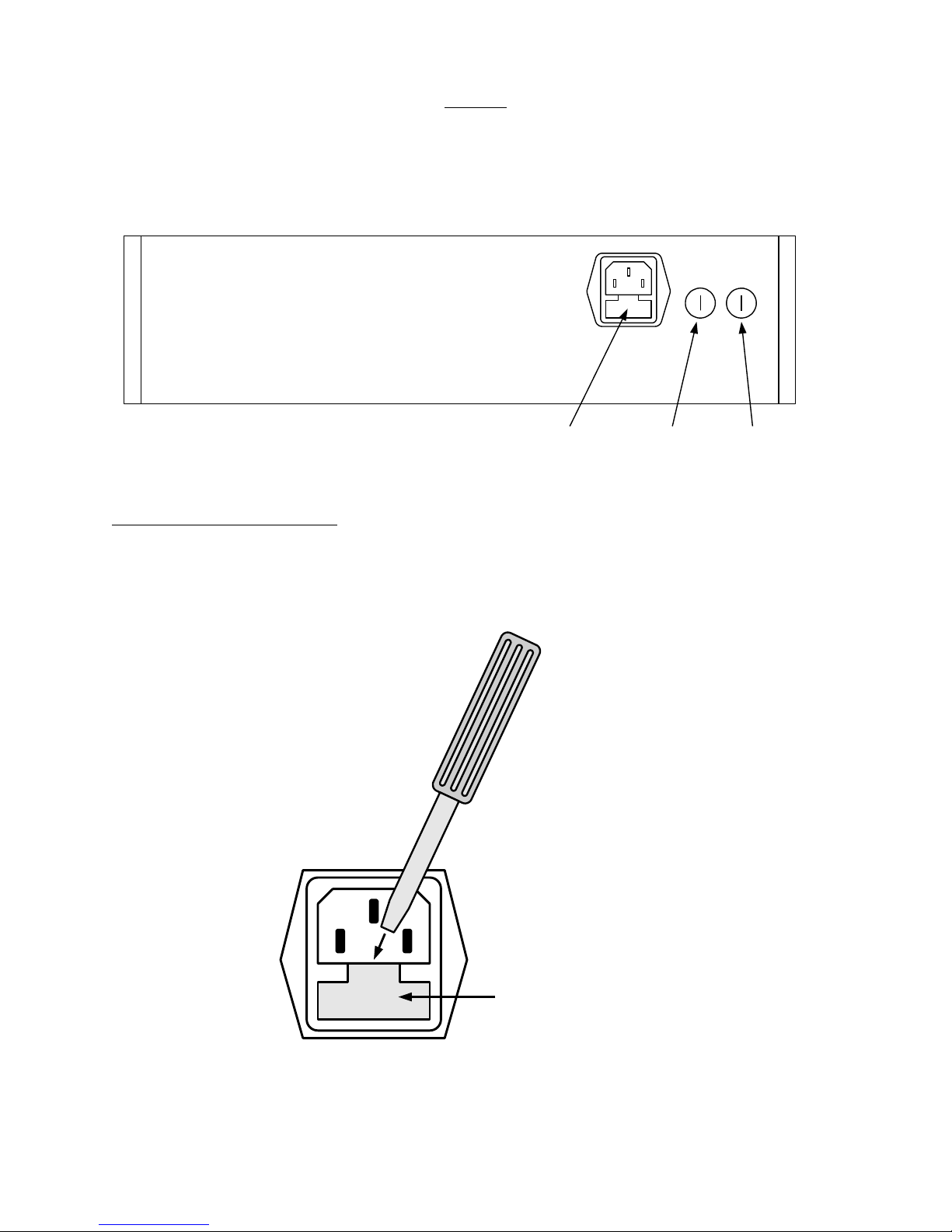
This instrument contains four fuses. All are accessible from the rear-panel. Two protect
the AC prime power input, and two protect the internal DC power supplies. The
locations of the fuses on the rear panel are shown in the figure below:
Fuses #1 and #2
(AC fuses)
Fuse #4
(DC fuse)
Fuse #3
(DC fuse)
AC FUSE REPLACEMENT
To physically access the AC fuses, the power cord must be detached from the rear
panel of the instrument. The fuse drawer may then be extracted using a small flat-head
screwdriver, as shown below:
Pry out the fuse
drawer using a
screwdriver.
Fuse
Drawer
Page 14
DC FUSE REPLACEMENT
The DC fuses may be replaced by inserting the tip of a flat-head screwdriver into the
fuse holder slot, and rotating the slot counter-clockwise. The fuse and its carrier will
then pop out.
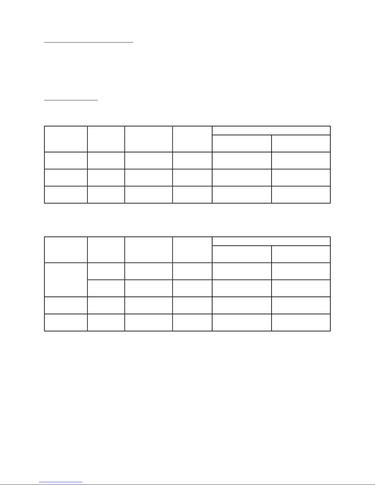
FUSE RATINGS
The following table lists the required fuses, for units without the -D option:
14
Nominal
Fuses
Mains
Rating Case Size
Voltage
#1, #2 (AC) 100-240V
#3 (DC) N/A
#4 (DC) N/A
0.5A, 250V,
Time-Delay
1.6A, 250V,
Time-Delay
1.0A, 250V,
Time-Delay
5×20 mm 0218.500HXP F2416-ND
5×20 mm 021801.6HXP F2424-ND
5×20 mm 0218001.HXP F2419-ND
Units with the -D option require larger fuses:
Nominal
Fuses
Mains
Rating Case Size
Voltage
115 V
#1, #2 (AC)
230 V
#3 (DC) N/A
#4 (DC) N/A
1.0A, 250V,
Time-Delay
0.5A, 250V,
Time-Delay
2.5A, 250V,
Time-Delay
2.0A, 250V,
Time-Delay
5×20 mm 0218001.HXP F2419-ND
5×20 mm 0218.500HXP F2416-ND
5×20 mm 021802.5HXP F2427-ND
5×20 mm 0218002.HXP F2420-ND
Recommended Replacement Part
Littelfuse Part
Number
Digi-Key Stock
Number
Recommended Replacement Part
Littelfuse Part
Number
Digi-Key Stock
Number
The recommended fuse manufacturer is Littelfuse (http://www.littelfuse.com).
Replacement fuses may be easily obtained from Digi-Key (http://www.digikey.com) and
other distributors.
Page 15

FRONT PANEL CONTROLS
The exact layout of the front panel will depend on the options ordered
15
1
2
3
1
4
5
4
2
3
6
5
Note: not all units will have all of the controls shown above
1. POWER Switch. This is the main power switch. When turning the instrument on,
there may be a delay of several seconds before the instrument appears to respond.
2. OVERLOAD Indicator. When the instrument is powered, this indicator is normally
green, indicating normal operation. If this indicator is yellow, an internal automatic
overload protection circuit has been tripped. If the unit is overloaded (by operating
at an exceedingly high duty cycle or by operating into a very low impedance), the
protective circuit will disable the output of the instrument and turn the indicator light
yellow. The light will stay yellow (i.e. output disabled) for about 5 seconds after
which the instrument will attempt to re-enable the output (i.e. light green) for about 1
second. If the overload condition persists, the output will be disabled again (i.e. light
yellow) for another 5 seconds. If the overload condition has been removed, the
instrument will resume normal operation.
Page 16

16
This overload indicator is only likely to come on in two situations:
Briefly at startup. This is not a cause for concern.
When the load impedance is too low (< 50 Ω). In this case, turn off the
instrument and connect the proper load.
3. IN Connectors. The input signal is applied to this connector (there are two
connectors on -D units). The input impedance is approximately 1 kΩ. The input must
not exceed ±2V.
4. GAIN Dial. This ten-turn dial is used to vary the amplifier gain between +1 and +15.
(There are two separate dials on -D units.) Units with the -INV option will also have
an INVERT / NON-INVERT switch, which changes the polarity (- or +) of the gain.
5. OUT Connector. This BNC connector provides the main output signal (there are two
connectors on -D units). The output is an amplified version of the input on (3). The
gain (V
OUT/VIN
) is controlled by (4).
6. OFFSET Controls. (Optional: -OS option only.) This dial varies the DC offset on the
output from 0 to ±15V. The ON/OFF switch below the dial enables and disables this
function. (-D units will have two sets of offset controls).
Page 17

REAR PANEL CONTROLS
31
2
1) AC POWER INPUT. An IEC-320 C14 three-pronged recessed male socket is
provided on the back panel for AC power connection to the instrument. One end of
the detachable power cord that is supplied with the instrument plugs into this
socket.
17
2) AC FUSE DRAWER. The two fuses that protect the AC input are located in this
drawer. Please see the “FUSES” section of this manual for more information.
3) DC FUSES. These two fuses protect the internal DC power supplies. Please see the
“FUSES” sections of this manual for more information.
Page 18

18
GENERAL INFORMATION
BASIC CONTROL
The AV-110D-PS is a DC-1 MHz variable-gain linear amplifier. The gain is variable from
0 to +15, and is adjusted by rotating the “GAIN” control.
Units with the -INV option can also be switched to inverting mode, where the gain is
variable from 0 to -15.
The required voltage input signal is applied at the “IN” connector.
This mode is illustrated below:
ARBITRARY
WAVEFORM,
VIN, ± 2V MAXIMUMINPUT VOLTAGE, ON
"IN" CONNECTOR
V
= VIN × GAIN,
OUT
GAIN = +1 TO +15,
OUTPUT VOLTAGE, ON
"OUT" CONNECTOR
ADJUSTABLE.
± 30V MAXIMUM.
If the instrument has the -OS option, a DC offset in the range of of -15V to +15V (for
-OS units) or -30V to +30V (for -XOS units) may be added to each output. The total
output voltage (amplified signal + DC offset) must remain within the range of -30V to
+30V.
CABLE LENGTHS
The length of cable used to connect the load to the output of the function generator
should be less than 3 feet (1 meter), and ideally less than 18 inches (0.5 meters) if the
load resistance is not 50 Ohms. At longer lengths, the transmission line reflections
caused by the cabling and the cable's capacitance will distort the output signal and
degrade the rise and fall times, particularly if the signals with fast rise times are used.
Page 19

OPERATIONAL CHECK
This section describes a sequence to confirm the basic operation of the instrument. It
should be performed after receiving the instrument. It is a useful learning exercise as
well.
SYNC OUTPUT
SIGNAL
SOURCE
(±2V maximum)
MAIN OUTPUT
19
AC
POWER
AVTECH
AMPLIFIER
CONNECTOR
CONNECTOR
OUT
SCOPE
IN
PROBE
SCOPE
PROBE
TEST LOAD,
50 Ω, 20W
REAL-TIME
OSCILLOSCOPE
CHANNEL A
CHANNEL B
TRIG
Basic Test Arrangement
1) Connect a 50 Ω, 20 W non-inductive test load between the OUT connector and
ground. A higher resistance may also be used, in which case the power rating may
be reduced. If cabling is used, keep it less than 3 feet / 1 meter in length.
2) Set the signal generator to produce a ±2V, 10 kHz waveform. (The input impedance
of the AV-110D-PS is 1 kΩ). Connect a cable from the SYNC connector of the signal
generator to the TRIG input of an oscilloscope. Set the oscilloscope to trigger
externally. Connect the main output of the signal generator to the input of the
amplifier.
3) Connect one oscilloscope probe (channel A) to the output of the signal generator.
Set the Channel A vertical scale to 1 V/div.
4) Connect one oscilloscope probe (channel B) to the 50 Ω load. On the oscilloscope,
set the channel A vertical scale to 20 V/div, and the horizontal scale to 100 us/div.
Page 20

5) Set the gain control to minimum (0.0). Turn on the amplifier and the signal
generator.
6) Rotate the gain control to its maximum setting. The Channel B waveform should
increase to ±30V, and have a shape similar to that of the Channel A waveform.
7) This completes the operational check.
20
Page 21

21
MECHANICAL INFORMATION
TOP COVER REMOVAL
If necessary, the interior of the instrument may be accessed by removing the four
Phillips screws on the top panel. With the four screws removed, the top cover may be
slid back (and off).
Always disconnect the power cord and allow the instrument to sit unpowered for 10
minutes before opening the instrument. This will allow any internal stored charge to
discharge.
There are no user-adjustable internal circuits. For repairs other than fuse replacement,
please contact Avtech (info@avtechpulse.com) to arrange for the instrument to be
returned to the factory for repair. Service is to be performed solely by qualified service
personnel.
Caution: High voltages are present inside the instrument during normal operation.
Do not operate the instrument with the cover removed.
RACK MOUNTING
A rack mounting kit is available. The -R5 rack mount kit may be installed after first
removing the one Phillips screw on the side panel adjacent to the front handle.
ELECTROMAGNETIC INTERFERENCE
To prevent electromagnetic interference with other equipment, all used outputs should
be connected to shielded loads using shielded coaxial cables. Unused outputs should
be terminated with shielded coaxial terminators or with shielded coaxial dust caps, to
prevent unintentional electromagnetic radiation. All cords and cables should be less
than 3m in length.
Page 22

MAINTENANCE
REGULAR MAINTENANCE
This instrument does not require any regular maintenance.
On occasion, one or more of the four rear-panel fuses may require replacement. All
fuses can be accessed from the rear panel. See the “FUSES” section for details.
CLEANING
If desired, the interior of the instrument may be cleaned using compressed air to
dislodge any accumulated dust. (See the “TOP COVER REMOVAL” section for
instructions on accessing the interior.) No other cleaning is recommended.
22
Page 23

WIRING DIAGRAMS
WIRING OF AC POWER
1 2 3 4 5 6
A
B
C
D
654321
D
C
B
A
T i t l e
R e v i s i o nD a te
3 0 - O c t - 2 0 1 3
Z : \ m j c f i l e s \ p c b \ 1 5 8 \ s w i t c h i n g 6 0 h z . d d b - U S A G E \ Q C 3 v 5 H - A A D . s c h
Q C 3 H A R N E S S , F O R P C B 1 5 8 P , T A M U R A A A D
5 H
+ 1 0 V
+ 1 5 V R E G
+ 1 5 V N S Y
- 1 5 V
- 5 V
+ 5 V R E G
+ 5 V N S Y
G N D
+ 2 4 V , N O O L O
+ 2 4 V , N O O L O
+ 1 0 V
+ 1 5 V
- 1 5 V
- 5 V
+ 5 V
G N D
G N D
+ 5 V
+ 5 V
+ 2 4 , N O O L O
G N D
P O S O L O
2 0 A W G
2 4 A W G
N E G O L O /+ IN
G N D
O L O G N D
2 0 O R 2 4 A W G
C A P B A N K
G N D
B U + / E X T P S
- I N / + O U T
G N D
G N D
G R E E N
G N D
A M B E R
2 0 A W G
P C B 1 5 8 P
+ 1 2 V O L O
G N D
K
A
-
+
J 1
J 2
J 3
J 4
J 5
J 6
J 7
J 8
+
J 9 - F A N
J 1 0
G N D
G N D
G N D
2 0 A W G
N / C
D C I N
D C I N
D C G N D
C H S G N D
N / C
B D 1
P C B 1 5 8 P - S I M P L I F I E D 2
F A IL
3
N
L
V 1 S H R
2
V 2 S H R
1
R T N
4
V 1 - S N S
5
V 1 + S N S
6
V 2 + S N S
7
V 2 - S N S
8
V 1
4
V 1 R T N
3
V 2 R T N
2
V 2
1
G
P S 1
A A D 1 3 0 S D - 6 0 - A
O V
T E M P
A U X
A
K
YBR
O
Y
G
T O L C D
T O P C B 1 0 8
T O E N C O D E RT O L C D
1 0 4 D
B D 2
P C B 1 0 4 D K E Y P A D B O A R D ( - B U N I T S O N L Y )
C h a s s i s g r o u n d p o s t .
G 1
G 2
B 1 - R E D
G 4
G 3
L
N
G
X 2
C O R C O M 6 E G G 1 - 2 P O W E R E N T R Y M O D U L E
1
1 b
1 a
2
2 b
2 a
X 1
P O W E R S W I T C H S W 3 2 5 -N D ( C W I N D U S T R I E S G R S - 4 0 2 2 - 0 0 1 3 )
A 1 - B R O W N
A 2 - B L U E
A 3 - B L A C K
A 4 - W H I T E
G R N
A M B
D 1
P 3 9 5 - N D L E D
G R N
A M B
B L K
R E D
W H T
X 5
V C C L E D M O U N T
D C
F A N
+
-
F A N 1
P 9 7 6 8 - N D
F A N N O T
C 3 - P U R
C 4 - G R N
M o le x 1 9 0 7 3 - 0 0 1 3 r i n g t e r m i n a l, # 8 .
M o le x 1 9 0 0 2 - 0 0 0 1 . 0 . 2 5 0 " x 0 . 0 3 2 " .
P r o t e c t i v e c o n d u c t o r t e r m i n a l .
M o le x 1 9 0 0 2 - 0 0 0 9 . 0 . 1 8 7 " x 0 . 0 3 2 "
P r i m a r y e a r t h g r o u n d /
S a f e t y e a r t h g r o u n d /
S e c o n d a r y e a r t h g r o u n d .
I n s t a l l g r e e n / y e l l o w w i r e s a t b o t t o m o f s t a c k , c lo s e s t t o w a ll .
M a i n s c i r c u it s - h a z a r d o u s l i v e .
W A R N I N G
D o n o t a t t e m p t a n y r e p a i r s o n t h i s i n s t r u m e n t
b e y o n d t h e f u s e r e p la c e m e n t p r o c e d u r e s d e s c r ib e d
i n t h e m a n u a l . C o n t a c t A v t e c h if t h e i n s t r u m e n t
r e q u i r e s s e r v i c i n g . S e r v i c e i s t o b e p e r f o r m e d
s o l e l y b y q u a l i f i e d s e r v i c e p e r s o n n e l .
H A R N E S S E D
U S E T I E - D O W N P O IN T O N P C B 1 5 8 N
F R O N T R E A R
Page 24

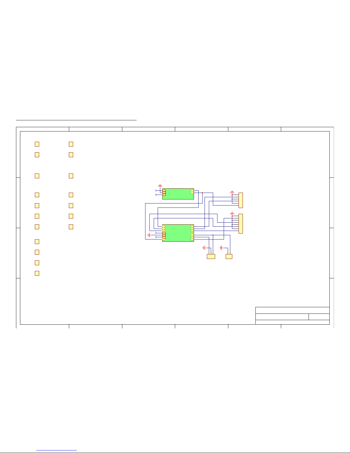
PCB 161C - LOW-VOLTAGE POWER SUPPLY
1 2 3 4 5 6
A
B
C
D
654321
D
C
B
A
T i t l e
R e v i s i o nD a t e
2 1 - M a y - 2 0 0 8
Z : \ m j c f i l e s \ p c b \ 1 6 1 \ F D C M O U N T I N G . d d b - D o c u m e n t s \ 1 6 1 C \ P C B 1 6 1 c . S C H
+
1
-
2
+ V O U T
5
T R I M
4
C T L
3
+ V O U T
6
C O M
7
C O M
8
- V O U T
9
- V O U T
1 0
G N D
G N D
G N D
G N D
U 1
A S T R O D Y N E F D C 6 0 - 2 4 D 1 2 D C - D C
C 6
2 . 2 u F
L 2
4 3 4 - 1 3 - 1 0 1 M
C 4
4 7 u F , 3 5 V
C 5
4 7 u F , 3 5 V
C 1
2 . 2 u F
L 1
4 3 4 - 1 3 - 1 0 1 M
C 2
4 7 u F , 3 5 V
C 3
4 7 u F , 3 5 V
1
2
3
J 1
6 4 0 4 4 5 - 3
1
2
3
4
5
J 2
6 4 0 4 4 5 - 5
X 1
H V W A R N I N G
F I L T +
U N F I L T -
C O M
L 3
4 3 4 - 1 3 - 1 0 1 M
U N F I L T +
F I L T -
C 7
4 7 u F , 3 5 V
F I L T +
U N F I L T -
C O M
U N F I L T +
F I L T -
F O R 1 0 1 X ,
F L O A T I N G + 2 4 V
T O F L O A T +
T O F L O A T -
N / C
N / C
N / C
F O R 1 5 5 C ,
T O G E N E R A T E - 1 5 V
N / C
- 1 5 V O U T
S H O R T T O U N F I L T S H O R T T O C O M
T O G N D
M I S C ,
T O G E N E R A T E - 2 4 V
N / C
- 2 4 V O U T
N / C
N / C
T O G N D
U S E F D C 6 0 - 2 4 D 1 2 U S E F D C 6 0 - 2 4 D 1 2U S E F D C 6 0 - 2 4 S 1 5
U S A G E C H A R T
X 2
H V W A R N I N G
1
2
3
J 3
M A S - C O N - 3 , 0 . 1 I N C H
Page 25
PCB 158P - LOW VOLTAGE POWER SUPPLY, 1/3
1 2 3 4 5 6
A
B
C
D
654321
D
C
B
A
T i t l e
R e v i s i o nD a te
2 9 - J u l- 2 0 1 4
Z : \ m j c f i l e s \ p c b \ 1 5 8 \ s w i t c h i n g 6 0 h z . d d b - 1 5 8 P \ p c b 1 5 8 P . s c h
L O W V O L T A G E D C / D C P O W E R S U P P L Y
123
J 5
6 4 0 4 5 6 - 3
1
2
3
4
5
6
7
8
J 4
6 4 0 4 4 5 - 8
1
2
3
4
5
6
J 3
6 4 0 4 4 5 - 6
+ 1 5 V
+ 1 5 V
B U +
P - O U T # 1
+ 1 5 V
G N D
- 1 5 V
p c b 1 5 8 P _ o v p
p c b 1 5 8 P _ o v p . s c h
B U +
P - O U T # 1
+ 1 5 V
G N D
- 1 5 V- 1 5 V
B U +
E X T
P - O U T # 2
N - O U T
N E G I N C A P B A N K
A M B E R
G R E E N
+ 1 5 V
G N D
- 1 5 V
P - O U T # 3P - O U T # 1
p c b 1 5 8 P _ s w i t c h i n g
p c b 1 5 8 P _ s w i t c h i n g . s c h
B U +
E X T
P - O U T # 2
N - O U T
N E G I N C A P B A N K
A M B E R
G R E E N
+ 1 5 V
G N D
- 1 5 V
P - O U T # 3P - O U T # 1
- 1 5 V
1
2
J 7
6 4 0 4 5 6 - 2
X 8
6 - 3 2 1 / 4 " S S S C R E W , 0 6 0 4 M P P 1 8 8
X 9
6 - 3 2 1 / 4 " S S S C R E W , 0 6 0 4 M P P 1 8 8
X 1 3
6 - 3 2 S S E X T T O O T H W A S H E R , 0 6 W E 1 8 8
X 1 4
6 - 3 2 S S E X T T O O T H W A S H E R , 0 6 W E 1 8 8
X 1 2
4 - 4 0 1 / 4 " S S S C R E W , 0 4 0 4 M P P 1 8 8
X 1 6
4 - 4 0 S S E X T T O O T H W A S H E R , 0 4 W E 1 8 8
X 1 7
2 - 5 6 1 / 4 " S S S C R E W , 0 2 0 4 M P P 1 8 8
X 1 9
2 - 5 6 S S E X T T O O T H W A S H E R , 0 2 W E 1 8 8
X 1 8
2 - 5 6 1 / 4 " S S S C R E W , 0 2 0 4 M P P 1 8 8
X 2 0
2 - 5 6 S S E X T T O O T H W A S H E R , 0 2 W E 1 8 8
X 4
2 - 5 6 1 / 4 " S S S C R E W , 0 2 0 4 M P P 1 8 8
X 2 3
2 - 5 6 S S E X T T O O T H W A S H E R , 0 2 W E 1 8 8
X 5
2 - 5 6 1 / 4 " S S S C R E W , 0 2 0 4 M P P 1 8 8
X 2 4
2 - 5 6 S S E X T T O O T H W A S H E R , 0 2 W E 1 8 8
X 2 5
# 2 S S F L A T W A S H E R , 0 2 W M 1 8 8
X 2 6
# 2 S S F L A T W A S H E R , 0 2 W M 1 8 8
X 2 7
# 2 S S F L A T W A S H E R , 0 2 W M 1 8 8
X 2 8
# 2 S S F L A T W A S H E R , 0 2 W M 1 8 8
Page 26

PCB 158P - LOW VOLTAGE POWER SUPPLY, 2/3
1 2 3 4 5 6
A
B
C
D
654321
D
C
B
A
T i t l e
R e v i s i o nD a te
2 9 - J u l- 2 0 1 4
Z : \ m j c f i l e s \ p c b \ 1 5 8 \ s w i t c h i n g 6 0 h z . d d b - 1 5 8 P \ p c b 1 5 8 P _ o v p . s c h
D C / D C , A N D O V E R - V O L T A G E P R O T E C T I O N
D 7
1 . 5 K E 3 9 A
T P 3
T E S T - L O O P
T P 6
T E S T - L O O P
A1A2B3X
4
F 3
F U S E H O L D E R
C 2 1
2 . 2 u F
C 2 0
4 7 u F / 5 0 V
L 5
7 7 A -1 0 0 M - 0 1
B U +
C 1 9
4 7 u F / 5 0 V
1
2
3
4
5
6
J 6
6 4 0 4 4 5 - 6
S 1 A
S 1 B , O R D C
S 2 A , O R D C
S 2 B
V i n
1
G N D
2
V o u t
3
U 5
N O T U S E D ( 7 8 2 4 )
C 1 3
4 7 u F / 5 0 V
C 7
4 7 u F / 5 0 V
R 5
0 O H M
P - O U T # 1
V i n
1
G N D
2
V o u t
3
U 2
7 8 1 0
123456789
J 2
6 4 0 4 4 5 - 9
+ 1 0 V
- 1 5 V
- 5 V
+ 5 V
+
3
+
1
-
2
-
5
C
4
U 1
P Y B 1 5 - Q 2 4 - D 1 5
+
3
+
1
-
2
-
5
C
4
U 4
P Y B 1 5 - Q 2 4 - D 5
+ 1 5 V
C 1 1
2 . 2 u F
L 3
7 7 A -1 0 1 M - 0 1
C 9
4 7 u F / 3 5 V
C 6
2 . 2 u F
L 2
7 7 A -1 0 1 M - 0 1
C 3
4 7 u F / 3 5 V
C 1
4 7 u F / 3 5 V
C 8
2 . 2 u F
L 1
7 7 A -1 0 1 M - 0 1
C 4
4 7 u F / 3 5 V
C 1 2
2 . 2 u F
L 4
7 7 A -1 0 1 M - 0 1
C 5
4 7 u F / 3 5 V
123456789
1 0
J 1
1 - 6 4 0 4 5 6 - 0
+ 1 0 V
+ 1 5 V R E G
+ 1 5 V N S Y
- 1 5 V
- 5 V
+ 5 V R E G
+ 5 V N S Y
G N D
+ 2 4 V
+ 2 4 V
+ 1 5 V
G N D
+ 1 5 V
- 1 5 V - 1 5 V
C 2 2
1 0 0 0 u F / 3 5 V
C 1 6
1 0 0 0 u F / 3 5 V
1
2
J 9
6 4 0 4 4 5 - 2
1
2
3
J 1 0
6 4 0 4 5 6 - 3
R 2 0
1 0 K
X 6
T I E - D O W N - 3 5 0
- I N2- I N
3
N / C9N / C
1 0
N / C
1 1
+ O U T
1 4
N / C
1 5
- O U T
1 6
+ I N
2 2
+ I N
2 3
U 9
N O T U S E D ( S B 0 3 / S B 0 5 )
+ I N1- O U T
1 0
+ O U T
1 1
- I N
1 2
- I N
1 3
+ O U T
1 4
- O U T
1 5
+ I N
2 4
N / C
2
N / C
2 3
N / C
3
N / C
2 2
U 8
N O T U S E D ( M K C 0 3 )
1
2
3
4
5
J 1 1
N O T U S E D ( 6 4 0 4 4 5 - 5 )
C 2 7
N O T U S E D ( 4 7 u F / 5 0 V )
C 2 8
N O T U S E D ( 4 7 u F / 5 0 V )
I N +
I N -
O U T +
O U T -
G N D
+
3
+
1
-
2
-
5
C
4
U 1 0
N O T U S E D
C 3 1
N O T U S E D ( 2 . 2 u F )
L 6
N O T U S E D ( 7 7 A - 1 0 1 M - 0 1 )
C 3 0
N O T U S E D ( 4 7 u F / 3 5 V )
1
2
3
4
J 1 2
N O T U S E D ( 6 4 0 4 5 6 - 4 )
C 2 9
N O T U S E D ( 4 7 u F / 3 5 V )
N O R M A L L Y U N U S E D
X 2 2
B A R E 1 5 8 P P C B
X 2 1
P C B 1 5 8 A L , V 2 B R A C K E T
V i n
1
G N D
2
V o u t
3
U 1 1
7 8 1 5
V i n
1
G N D
2
V o u t
3
U 1 2
7 8 0 5
F O R N O IS Y S U B C I R C U I T S
C 3 2
4 7 u F / 3 5 V
C 3 3
4 7 u F / 3 5 V
R 3 0
0 O H M
R 2 9
N O T U S E D ( 0 )
Page 27

PCB 158P - LOW VOLTAGE POWER SUPPLY, 3/3
1 2 3 4 5 6
A
B
C
D
654321
D
C
B
A
T i t l e
R e v i s i o nD a te
2 9 - J u l- 2 0 1 4
Z : \ m j c f i l e s \ p c b \ 1 5 8 \ s w i t c h i n g 6 0 h z . d d b - 1 5 8 P \ p c b 1 5 8 P _ s w i t c h i n g . s c h
O V E R - C U R R E N T P R O T E C T I O N
-
3
+2-
1
+
4
K 3
A Q Z 1 0 2
D 4
1 N 5 3 0 5
R 1 4
5 . 1 K
D 2
1 N 4 7 3 3 A
R 1 0
1 2 0 O Y
E X T
A1A2B3X
4
F 2
F U S E H O L D E R
-
3
+2-
1
+
4
K 1
A Q Z 1 0 2
-
3
+2-
1
+
4
K 2
N O T U S E D ( A Q Z 1 0 2 )
D 1
1 N 4 7 3 6 A
V +
8
R E S E T
4
T R I G
2
T H R
6
C O N T
5
D I S
7
G N D
1
O U T
3
U 7
S E 5 5 5 P
R 7
7 5 K
R 1 1
4 . 7 K
R 9
3 K
+ 1 5 V
R 1 2
1 K
P - O U T # 2
81 0
Q 1 D
M P Q 2 2 2 2
13
Q 1 A
M P Q 2 2 2 2
N - O U TN E G I N
R 1
N O T U S E D ( 0 )
- 1 5 V
C A P B A N K
A M B E R
R 1 9
6 8 0
75
Q 1 B
M P Q 2 2 2 2
R 1 6
1 . 2 K
+ 1 5 V
R 1 8
1 . 2 K
G R E E N
C 1 0
4 7 u F / 5 0 V
T P 5
T E S T - L O O P
T P 4
T E S T - L O O P
1
2 3
4
K 4
P S 7 2 0 6 - 1 A - F 3 - A
+ 1 5 V
T P 2
T E S T - L O O P
T P 1
T E S T - L O O P
C 1 7
0 . 1 u F
C 1 4
4 7 u F / 3 5 V
C 1 5
0 . 1 u F
- 1 5 V
X 3
6 - 3 2 M O U N T
X 1 0
6 - 3 2 M O U N T
1 41 2
Q 1 C
M P Q 2 2 2 2
D I S A B L E O L O W H E N C H A R G I N G .
S H O R T S O U T B A S E W H E N C H A R G I N G .
B U +
+ 1 5 V
G N D
- 1 5 V
X 1
K E Y S T O N E 6 2 1
R 1 5
0 O H M
R 1 7
N O T U S E D ( 0 )
C 2 3
1 0 0 0 u F / 3 5 V
C 1 8
2 2 0 u F , 1 6 V
C 2
N O T U S E D ( 1 0 0 0 u F / 3 5 V )
R 2
N O T U S E D ( 2 2 A Y )
D 6
L E D
X 2
H V W A R N I N G
D 9
1 N 4 1 4 8
D 1 0
1 N 4 1 4 8
+ 1 5 V
D I S A B L E A T P O W E R - O F F
D I S A B L E A T P O W E R - O N
C 2 4
4 7 u F / 3 5 V
R 4
1 5 0
( + 1 5 V L A G S H V B Y 5 0 0 m s )
V i n
1
G N D
2
V o u t
3
U 3
7 8 1 2
C 2 5
4 7 u F / 5 0 V
R 2 1
1 . 5 K O Y
C 2 6
0 . 1 u F
P - O U T # 3
P - O U T # 1
R 3
3 0 0
R 2 2
3 0 0
R 8
W L A R 1 0 0 F E ( 0 . 1 O H M S )
4
3
2
15
K 5
N O T U S E D ( G 2 R L - 1 4 - D C 2 4 )
1 2
3
D 5
2 5 C T Q 0 4 0 P B F , I N 5 9 1 2 0 2 B 0 4 0 0 0 G H E A T S I N K
R 6
4 7 0
R 1 3
4 7 0
-
3
+2-
1
+
4
K 6
N O T U S E D ( A Q Z 1 0 2 )
R 2 4
4 7 0
R 2 3
4 7 0
R 2 5
W L A R 1 0 0 F E ( 0 . 1 O H M S )
- I N3G N D
2
+ I N
4
V +
5
O U T
1
U 6
L T 6 1 0 6 C S 5
R 2 6
1 5 K
R 2 7
1 0 0
X 7
5 9 1 2 0 2 B 0 4 0 0 0 G H E A T S I N K , I N S T A L L E D A S L O W A S P O S S I B L E
-
3
+2-
1
+
4
K 7
N O T U S E D ( A Q Z 1 0 2 )
R 2 8
0 O H M
Page 28
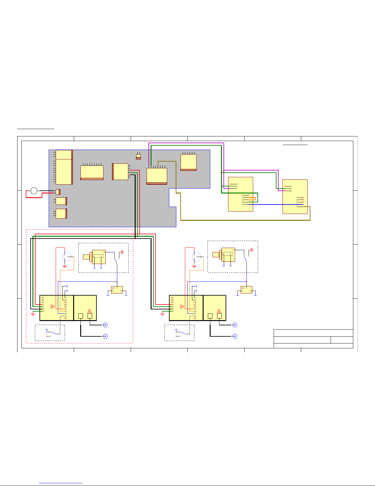
MAIN WIRING
1 2 3 4 5 6
A
B
C
D
654321
D
C
B
A
Ti tle
Revis io nDate
11-Aug-2014
Z:\mjcfil es\circuits\av-11X-15X\FUNC.ddb - AV-110D-PS\110d v5.sch
AV-110D-PS, WITH -OS, -D, -INV OPTIONAL
5B
+10 V
+15 V REG
+15 V NSY
-15 V
-5V
+5V R EG
+5V NS Y
GND
+24 V, NO OLO
+24 V, NO OLO
+10 V
+15 V
-15 V
-5V
+5V
GND
GND
+5V
+5V
+24 , NO O LO
GND
POS OLO
20 A WG
24 A WG
NEG OLO/+ IN
GND
OLO GND
20 OR 24 AW G
CA P B ANK
GND
BU +/EXT PS
-IN/+O UT
GND
GND
GR EEN
GND
AMB ER
20 AWG
PC B 1 58 P
+12 V OLO
GND
K
A
+
J1
J2
J3
J4
J5
J6
J7
J8
+
J9 - FAN
J10
GND
GND
GND
20 AWG
N/C
DC IN
DC IN
DC GN D
CH S GN D
N/C
DC
FAN
+
-
FAN 1
P97 6 8-ND
+HV
-HV
OUT
IN
GND
GND
GND
GND
LV+
N/C
BU F
N/C
AMP
N/C
-15 V
+15 V
INV
OS
N/C
PG B
AV-1 10 D-PG
SW1
OS
ON
OFF
CC W
CW
W
R2
5K , OS B
+15 V
-15 V
CHS GND
-15 V +1 5 V
CO NN1
OUT B
CO NN2
IN B
CC W CW
W
R3
AMP B, 50 0 OHM , ON E-TUR N (1 0 T TOO SLOW )
PCB158 CHANGES
1. USE AAD130SD-80 INSTEAD OF "-60"
2. ADD U5 = 78 24
3. REMO VE R5 AND R13
IN+
1
IN-
2
CTL
3
FILT+
1
CO M
2
UNFI LT-
3
UNF ILT+
4
FILT-
5
N-120 1-11 5-0 sp acer s
X1
FDC 60 -24 S1 2 WITH PC B1 61 B
IN+
1
IN-
2
CTL
3
FILT+
1
COM
2
UNF ILT-
3
UNFI LT+
4
FILT-
5
N-120 1-1 15-0 sp ace rs
X2
FDC 60 -24 D1 2 WITH PCB 1 61 B
+36 V NO OLO
+HV
-HV
OUT
IN
GND
GND
GND
GND
LV+
N/C
BU F
N/C
AMP
N/C
-15 V
+15 V
INV
OS
N/C
PG A
AV-1 10 D-PG
SW2
OS
ON
OFF
CC W
CW
W
R1
5K , OS A
+15 V
-15 V
CHS GND
-15 V +1 5 V
CO NN3
OUT A
CO NN4
IN A
CC W CW
W
R4
AMP A, 50 0 OHM , ON E-TUR N (10 T T OO S LOW )
-36V NO OLO
4. INSTALL K2 = AQZ102
SW4
+15 V
INV
NON-I NV
-INV UNITS ONLY
SW3
+15 V
INV
NON-I NV
-INV UNITS ONLY
-D UNITS ONLY
-12V
-OS UNITS ONLY
-OS UNITS ONLY
5. INSTALL K5 = G2RL-14-DC24
6. INSTALL R2 = 22 AY
CC W CW
W
TOP V IEW
R6
50 0K, 32 6 6W , O S N ULL
+15 V -15 V
CC W CW
W
TOP V IEW
R5
50 0K, 32 6 6W , O S N ULL
+15 V -15 V
Page 29

PERFORMANCE CHECK SHEET
29
 Loading...