

Page 1

MAGIC THipPro
ISDN, POTS & VoIP Telephone Hybrid
Hardware Manual
P
r
e
l
i
mi
n
a
r
y
Page 2

.
Page 3

MAGIC THipPro
ISDN, POTS & VoIP Telephone Hybrid
Hardware Manual
To get automatically informed about the latest soft-
ware, please register on our homepage:
http://www.avt-nbg.de
Please click on Create an account under the Log In
section. Now you need to enter your name/com-
pany, a user name and a valid email address.
Please click on Register to receive your confirmation
email which includes the link to activate your ac-
count.
With your account you can also download manuals
and the latest software in the Download section of our
website.
Page 4

Page 5

A publication of:
AVT Audio Video Technologies GmbH
Nordostpark 12
D-90411 Nuernberg
Telephone +49-911-5271-0
Telefax +49-911-5271-100
Printed in Germany, May.2013
© AVT Audio Video Technologies GmbH
All rights reserved. Reproduction in
whole or in parts is prohibited without
previous written consent of Audio Video
Technologies GmbH.
Subject to change.
Release date: (05.13)
Page 6

.
Page 7

Content
Content
INTRODUCTION 9
SAFETY 11
Introduction 11
General safety requirements 11
Conventions 12
1CONSTRUCTION13
2 SYSTEM DESCRIPTION 15
2.1 Functionality 15
3 PUTTING THE SYSTEM INTO OPERATION 17
3.1 Mounting 17
3.2 Connection to the mains voltage 17
3.3 Earthing of the system 17
3.4 Operating elements on the front side 18
3.5 Alarm indication LEDs 18
3.6 Operating modes of the system 19
3.6.1 POTS operating mode 19
3.6.2 ISDN operating mode 20
3.6.3 VoIP operating mode 21
3.7 Applications 22
3.7.1 Two studios with presenter and one screener location 22
3.7.2 Two studios in redundancy operation 23
3.7.3 MAGIC THipPro with MAGIC Admin Upgrade 24
A1 INTERFACES 25
A1.1 MAGIC THipPro 25
A1.2 Control and data interfaces 26
A1.2.1 LAN 1 and LAN 2 interfaces 26
A1.2.2 ISDN Line Interfaces 26
A1.2.3 POTS Line Interfaces 27
A1.2.4 TTL/RELAY interface 28
A1.2.5 RS232/Keypad Interfaces 28
A1.2.6 Extension Bus 28
A1.3 Audio interfaces 29
Page 8

Content
A1.3.1 Handset/Headset In terfaces 29
A1.3.2 Analogue Audio interfaces 29
A1.3.3 Digital AES/EBU Audio Interfaces 30
A2 TECHNICAL DATA MAGIC THIPPRO 31
A3 GENERAL 34
A3.1 Order numbers 34
A3.2 Scope of delivery 36
A3.3 Declaration of conformity 36
A4 SERVICE INFORMATION 37
A4.1 Software Updates 37
A4.2 Support 37
A4.3 Repairs 37
DECLARATION OF CONFORMITY 39
Page 9

PAGE 9
Introduction
INTRODUCTION
MAGIC THipPro is available in three basic vers ions (POTS, ISDN or VoI P). In
the POTS version, maximum eight caller lines can be provided. In the ISDN
and VoIP version systems for eight and for sixteen lines are available.
Via the two LAN interfaces on the rear side of the unit, system control and
VoIP connections are realised. Independent from the type of the line interfaces MAGIC THipPro provides eight digital Audio lines ( f ou r AES/EBU interfaces) as well as two analogue Audio inputs and outputs. Additionally,
two handset/headset interfaces can be used for Pretalk.
MAGIC THipPro has an integrated wide area power supply, a keypad with
display and LEDs on the front side.
English
Deutsch
Menu
Select
System Settings
System Settings
Language
Sprache
Cap
Ok
Save Settings?
Yes
No
Operation Settings
Select
Line Mode
ISDN
ISDN Single Hybrid
POTS
Audio
Audio Settings
Audio Settings
Audio Input
Audio Output
Analogue
Digital
PRETALK Interface
No Device
Phone
Handset
Delete
Opts.
ON AIR
HOLD
PRETALK
Call Out...
Callin
Disconnect
Locked
Line
Ring Tone
Search
Names
New Entry
Page 10

PAGE 10
Introduction
Edit
View
Delete Entry
Save as Quick dial
Presets
Load
New
Save
Delete Preset
Ring Tone
Signal Processing
Keypad 9600, none
Status Information
Login
Shift
Page 11

PAGE 11
Safety
SAFETY
Introduction
The unit described is designed to the latest technical parameters and complies
with all national and international safety requirements. It operates with a high
level of operational safety resulting from long development experience and
stringent quality control in our company.
In normal operation this equipment is safe.
There are, however, some potential sources of danger that cannot be completely eliminated.
This Operator Manual therefore contains basic safety instructions that must
be observed during system configuration and opera tion. The O perato r Manual must be read before the system is used and the current version o f the document must always be kept close to the equipment.
General safety requirements
In order to keep the technically unavoidable residual risk to a minimum it is
imperative to observe the following rules:
– Transport, storage and operation of the unit/system must be under the
permissible conditions only.
– Installation, configuration and disassembly must be carried out only by
trained personnel and with reference to the respective documentation.
– The system must be operated by knowledgeable and authorised users
only.
– The system/unit must not be operated unless it is in good working order.
– Any conversions or alterations to the system or parts of the system (includ-
ing the software) must be carried out by qualified personnel from the manufacturer or by expert personnel authorised by our company.
All alterations carried out by other persons lead to a complete exemption
from liability.
– The removal or disabling of safety measures, the correction of faults and
errors, and the maintenance of equipment must be carried out by specially
qualified personnel only.
– Non-system software is used at one‘s own risk. The use/installation of
non-system software can adversely affect the normal functioning of the
system.
– Only use tested and virus-free data carriers.
Page 12

PAGE 12
Sicherheit
Conventions
In this manual, the following conventions are used as text markers:
Emphasis: Product names or important terms
LCD Text
: Labelling on the front display of the system
PC Text: Labelling in the PC software
TIP
The symbol TIP labels information which facilitates the operation of the system in its daily use.
NOTE
The symbol NOTE labels general notes to observe.
ATTENTION The symbol ATTENTION labels very important advice that is absolutely to
observe. In case of non-observance disfunctions and even system errors are
possible.
!
Page 13
PAGE 13
Construction
1 CONSTRUCTION
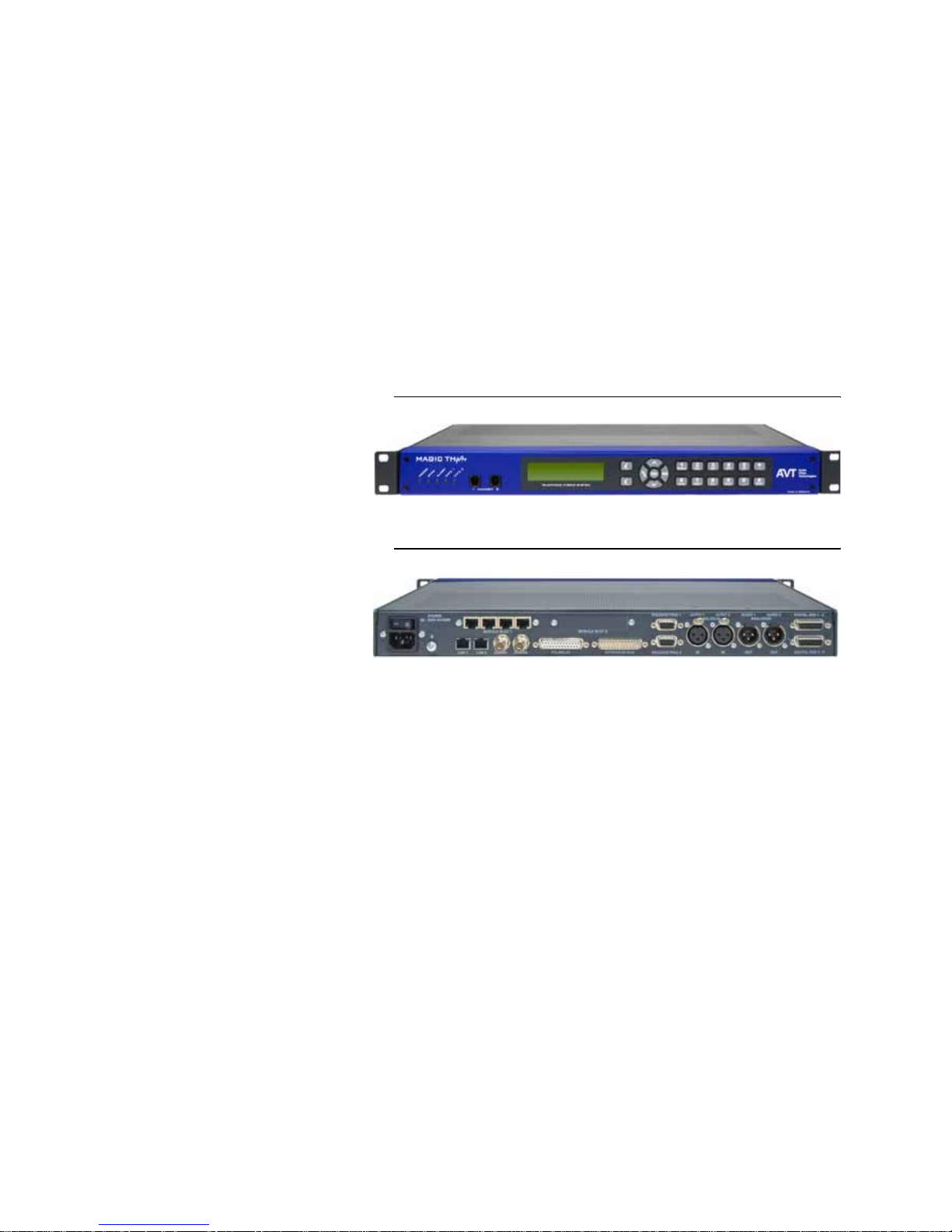
MAGIC THipPro contains a mainboard with an additional connector, a display, a keypad and five LEDs. For the ISDN and POTS version two modules
with the POTS or the ISDN components can be put on the mainboard.
The functions of the MAGIC THipPro are implemented in a 19" unit with 1U
and the dimensions of 434 mm x 44,5 mm x 252 mm. MAGIC THipPro can be
used as a table-top device or it can be mounted in 19" racks. There are some
ventiliation holes for a good ventilation.
FIG. 1 FRONT VIEW: MAGIC THIPPRO
FIG. 2 REAR VIEW: MAGIC THIPPRO EQUIPPED WITH ONE MODULE
Page 14

PAGE 14
Systembeschreibung
Page 15

PAGE 15
System Description
2 SYSTEM DESCRIPTION
2.1 Functionality
MAGIC THipPro is available in three basic versions (POTS, ISDN or VoIP). In
the POTS version, maximum eight caller lines can be provided. In the ISDN
and VoIP version, systems for eight lines as well as for sixteen lines are available.
Via the two LAN interfaces on the rear side of the unit system control and
VoIP connections are realised. Independent from the type of the line interfaces MAGIC THipPro provides eight digital Audio lines (four AES/EBU interfaces) as well as two analogue Audio inputs and outputs. Additionally,
two handset/headset interfaces can be used for Pretalk.
The Hold signal can be an external, an internal (recorded or imported as file)
signal or the On Air signal. Up to four different internal Hold signals can be
defined.
MAGIC THipPro has an illuminated graphical display with a resolution of
160 x 32 pixels and a front keypad, which can be used for basic settings and
status indications.
With the Telephone Hybrid up to 16 callers can be switched ON AIR or in
PRETALK simultaneously. Additionally, there are two configurea ble call f orwarding functions.
To optimize the Audio quality a digital Echo Canceller, an Automatic Gain
Control (AGC) and an Expander for noise suppression are available for each
caller line.
Page 16

PAGE 16
System Description
Page 17

PAGE 17
Putting the system into operation
3 PUTTING THE SYSTEM INTO OPERATION
3.1 Mounting
With its dimensions (W × H × D) of 434 mm × 44,5 mm (1 U) × 252 mm the
MAGIC THipPro system can be either used as desktop device or mounted in
a 19 inch rack. Corresponding 19“ mounting brackets are included in delivery.
When mounting the unit please keep in mind that the bending radius of the
cables is always greater than the minimum allowed value.
When the MAGIC THipPro Telephone Hybrid is installed, please make sure
that there is sufficient a ir ven til ati on : It is recommended to keep a spacing of
ca. 3 cm from the openings. In general, the ambient temperature of the system
should be within the range of +5°C and +45°C. These limits are especially to
observe if the system is inserted in a rack. The systems works without ventilation.
During operation air humidity must range between 5% and 85%.
3.2 Connection to the mains voltage
The system can be operated with mains voltage in the range from 90 V to
253 V via the internal power supply and the mains type appliance cable. The
line frequency can vary from 45 Hz to 65 Hz. The maximum power consumption is 15W. The rack must be earthed according to the EMC regulations. The
earthing can be carried out via the earthing screw on the back side of the unit.
The unit has a circuit closer. After plugging in the mains type appliance cable
and pressing the circuit closer, the system boots within a few seconds.
3.3 Earthing of the system
For EMC reasons an earthing via the earthing screw of the system must be car-
TIP
The system temperature can be indicated on the display.
ATTENTION Incorrect ambient temperature and humidity can cause functional defi-
ciencies.
Operation outside the threshold values indicated above leads to a loss of warranty claim.
!
Page 18
PAGE 18
Putting the system into operation
ried out in either case.
3.4 Operating elements on the front side
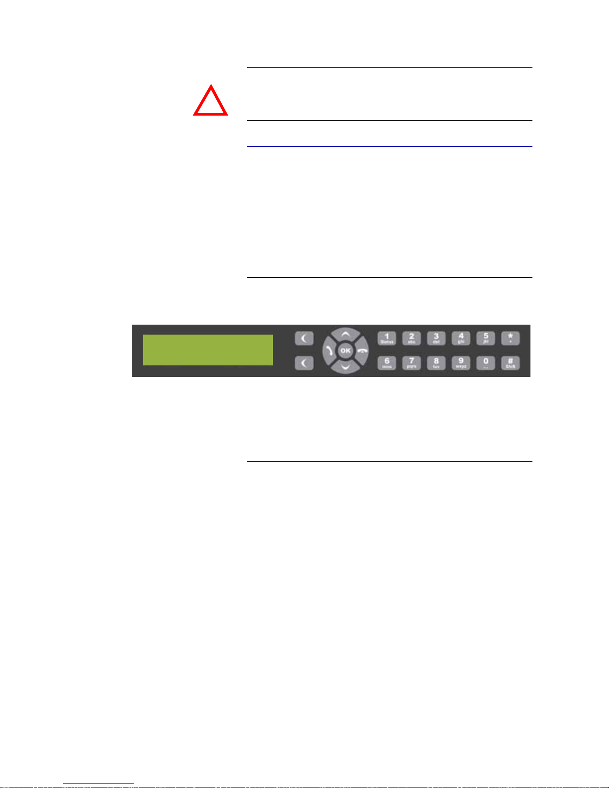
The system has an illuminated graphical display with a resolution of 160 x 32
Pixels and 21 operating buttons.
On the right next to the display there are two softkeys whose current functions are indicated on the display. In the middle there are two buttons for navigation (selection upwards/downwards) and the
OK
button. The numerical
pad supports in addition to the numericals
0...9
also the ’*’and ’#’button. For
entering text the numerical pad can also be used as a normal keypad.
FIG. 3 OPERATING ELEMENTS ON THE FRONT SIDE
3.5 Alarm indication LEDs
The MAGIC THipPro has five LEDs for status indication.
(1) POWER green
Lights up when system is ready for operation.
(2) SYNC green
Lights up if at least one telephone connection is established.
(3) ALARM red
Lights up if a fault has occurred in the unit. The Windows PC software
provides more detailed information about the error.
(4) INFO 1 orange
(5) INFO 2 orange
ATTENTION Earthing
A lacking earthing can cause functional deficiencies within the unit.
!
Page 19
PAGE 19
Putting the system into operation
3.6 Operating modes of the system
The following figures show the system in the different operating modes and
their respective cablings.
3.6.1 POTS operating mode
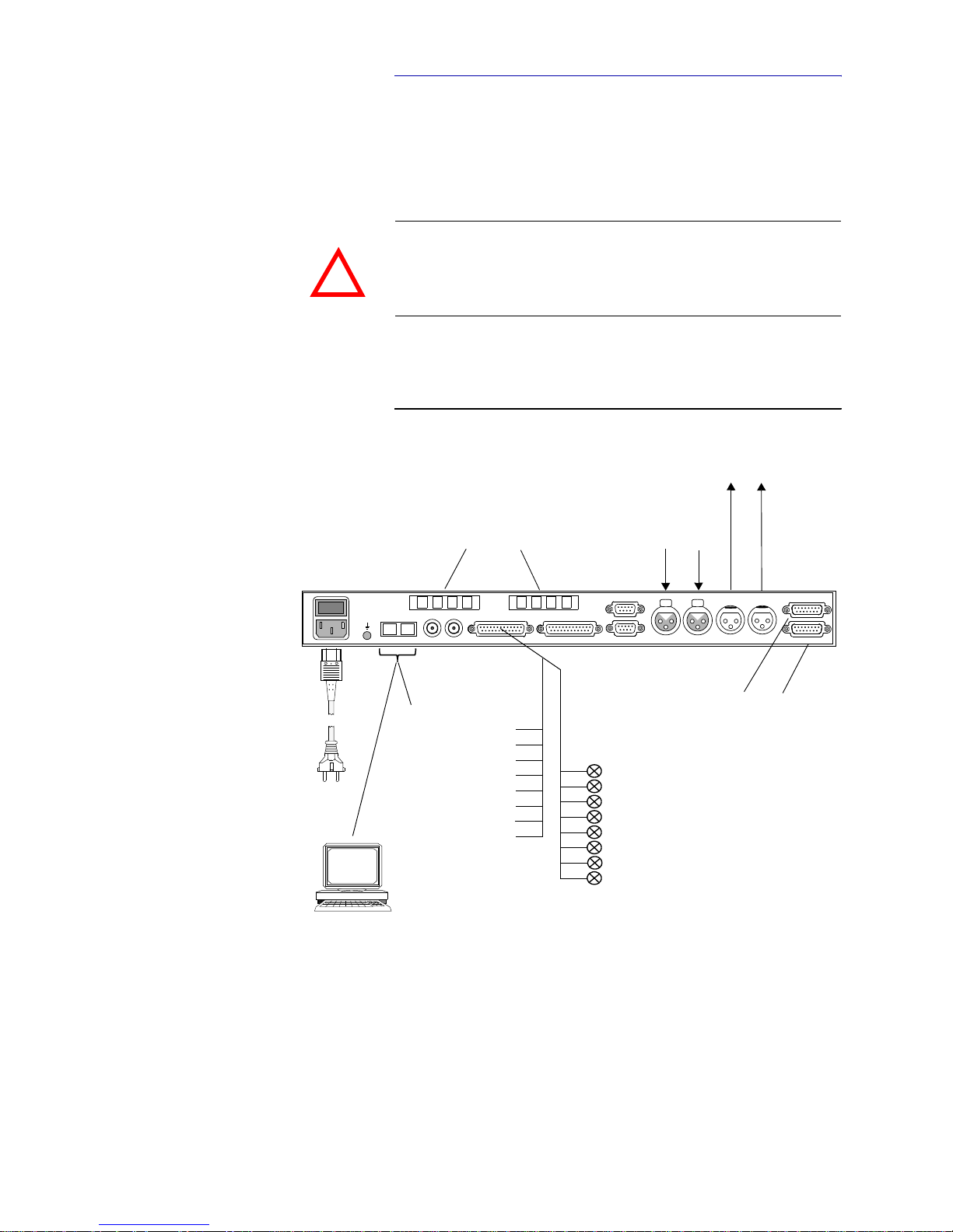
The wiring for the operation is pictured in Fig. 4. MAGIC THipPro POTS can
be equipped with two fourfold POTS modules and can be used as a eight line
POTS Hybrid.
FIG. 4 WIRING OF THE MAGIC THIPPRO POTS
ATTENTION Earthing
If the POTS interfaces are in operation, the system must be earthed via earthing screw for EMC reasons. If the earthing is not carried out, the Audio signal
can be faulty on the caller’s side (humming).
!
POWER
EXTENSION BUS
Digital AES 3-4
Digital AES 1 -2
RS232/KEYPAD 1
I0
90- 250V AC/30W
LAN 1 LAN 2
AUDIO 1 AUDIO 2 AUDIO 1 AUDIO 2
IN IN OUT O U T
power
RS232/KEYPAD 2TTL/RELAY
ANALOGUE
CLOCK 1 CLOCK 2
ANALOGUE
MODULE SLOT 1
MODULE SLOT 2
2 x POTS Modules for 8 caller channels
Analogue
Analogue
4 x AES Audio In-/Outputs
(8 x digital Audio lines)
up to 20 PCs with
MAGIC THipPro LAN and
MAGIC THipPro Screener Software
TTL 1
TTL 2
TTL 3
TTL 4
TTL 5
TTL 6
TTL 7
TTL 8
8 programmable Relays
REL 1
REL 2
REL 3
REL 4
REL 5
REL 6
REL 7
REL 8
8 programmable
VoIP
TTL Inputs/Outputs
telephony
Audio Inputs
Audio Outputs
supply
(Optional)
Page 20
PAGE 20
Putting the system into operation
3.6.2 ISDN operating mode
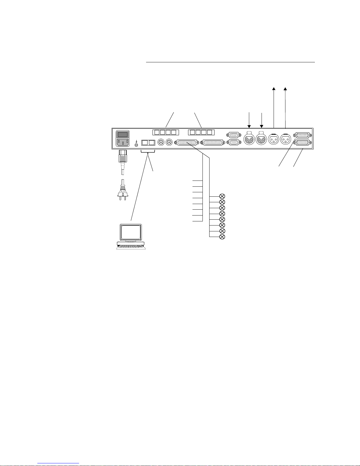
MAGIC THipPro can be equipped with two fourfold ISDN BRI modules and
can be used as a eight or a 16 line ISDN Hybrid.
FIG. 5 WIRING IN OF THE MAGIC THIPPRO ISDN
POWER
EXTENSION BUS
Digital AES 3-4
Digital AES 1 -2
RS232/KEYPAD 1
I0
90- 250V AC/30W
LAN 1 LAN 2
AUDIO 1 AUDIO 2 AUDIO 1 AUDIO 2
IN IN OUT OUT
power
RS232/KEYPAD 2TTL/RELAY
ANALOGUE
CLOCK 1 CLOCK 2
ANALOGUE
MODULE SLOT 1
MODULE SLOT 2
2 x ISDN Modules for 16 caller channels
Analogue
Analogue
4 x AES Audio In-/Outputs
(8 x digital Audio lines)
up to 20 PCs with
MAGIC THipPro LAN and
MAGIC THipPro Screener Software
TTL 1
TTL 2
TTL 3
TTL 4
TTL 5
TTL 6
TTL 7
TTL 8
8 programmable Relays
REL 1
REL 2
REL 3
REL 4
REL 5
REL 6
REL 7
REL 8
8 programmable
VoIP
TTL Inputs/Outputs
telephony
Audio Inputs
Audio Outputs
supply
(Optional)
1 x ISDN Modules for 8 caller channels or
Page 21
PAGE 21
Putting the system into operation
3.6.3 VoIP operating mode
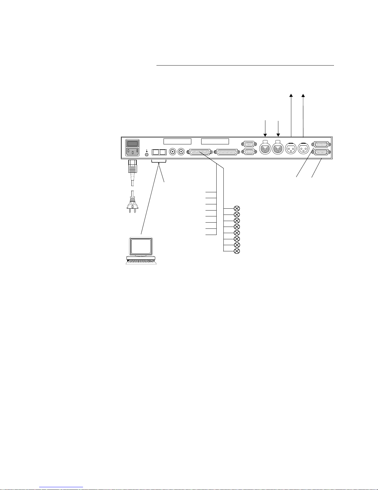
MAGIC THipPro can act as a eight or 16 line Hybrid. One of the LAN interfaces can be used.
FIG. 6 WIRING OF THE MAGIC THIPPRO VOIP
POWER
EXTENSION BUS
Digital AES 3-4
Digital AES 1 -2
RS232/KEYPAD 1
I0
90- 250V AC/30W
LAN 1 LAN 2
AUDIO 1 AUDIO 2 AUDIO 1 AUDIO 2
IN IN OUT OUT
power
RS232/KEYPAD 2TTL/RELAY
ANALOGUE
CLOCK 1 CLOCK 2
ANALOGUE
MODULE SLOT 1
MODULE SLOT 2
Analogue
Analogue
4 x AES Audio In-/Outputs
(8 x digital Audio lines)
up to 20 PCs with
MAGIC THipPro LAN and
MAGIC THipPro Screener Software
TTL 1
TTL 2
TTL 3
TTL 4
TTL 5
TTL 6
TTL 7
TTL 8
8 programmable Relays
REL 1
REL 2
REL 3
REL 4
REL 5
REL 6
REL 7
REL 8
8 programmable
VoIP
TTL Inputs/Outputs
telephony
Audio Inputs
Audio Outputs
supply
Page 22
PAGE 22
Putting the system into operation
3.7 Applications
Below you will find some example applications with MAGIC THipPro.
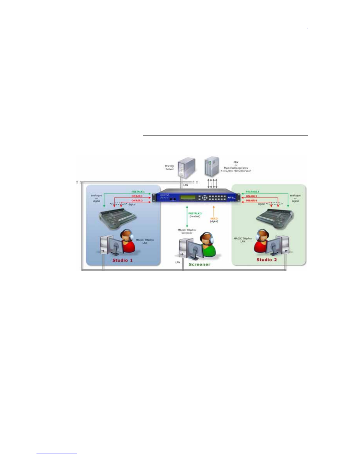
3.7.1 Two studios with presenter and one screener location
If MAGIC THipPro 8 is used, eight common caller lines are available for both
studios. In each studio all eight lines are displayed. The MAGIC THipP ro
LAN Software is installed for the workplaces in the studios. The Screener
works with the MAGIC THipPro Screener Software. Each Presenter has his
own Pretalk line and two On Air lines to realize a Two Faders operation. The
Screener uses a headset for Pretalk which is directly connected to the telephone hybrid. Additionally, an external signal can be fed in as Hold signal.
Alternatively, the On Air or a recorded signal can be used for Hold.
FIG. 7 APPLICATION WITH TWO STUDIOS
Page 23
PAGE 23
Putting the system into operation
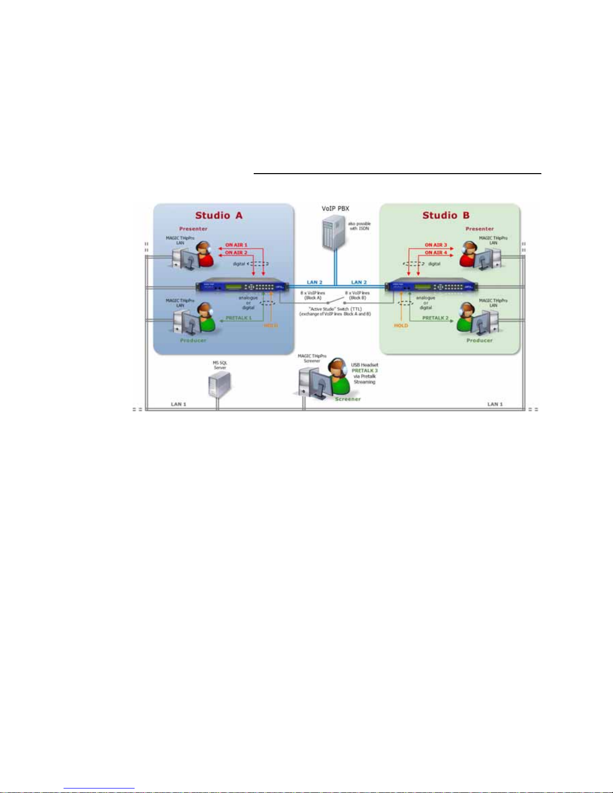
3.7.2 Two studios in redundancy operation
Two identical studios are equipped with two MAGIC THipPro ISDN or VoIP
systems. Studio A is used as active studio whereas Studio B is used as backup.
To each studio a block of eight caller lines is allocated. The Presenter and the
Producer use the MAGIC THipPro LAN Software in the studios. The Screener
workplace is connected via Pretalk Streaming and works with a USB Headset
that is directly connected to the Screener PC. In this way, in case of a backup
the Screener has access to Studio B just by activating a preset. The caller lines
can be switched via a TTL contact (switch "Active Studio").
FIG. 8 APPLICATION WITH REDUNDANCY
Page 24
PAGE 24
Putting the system into operation
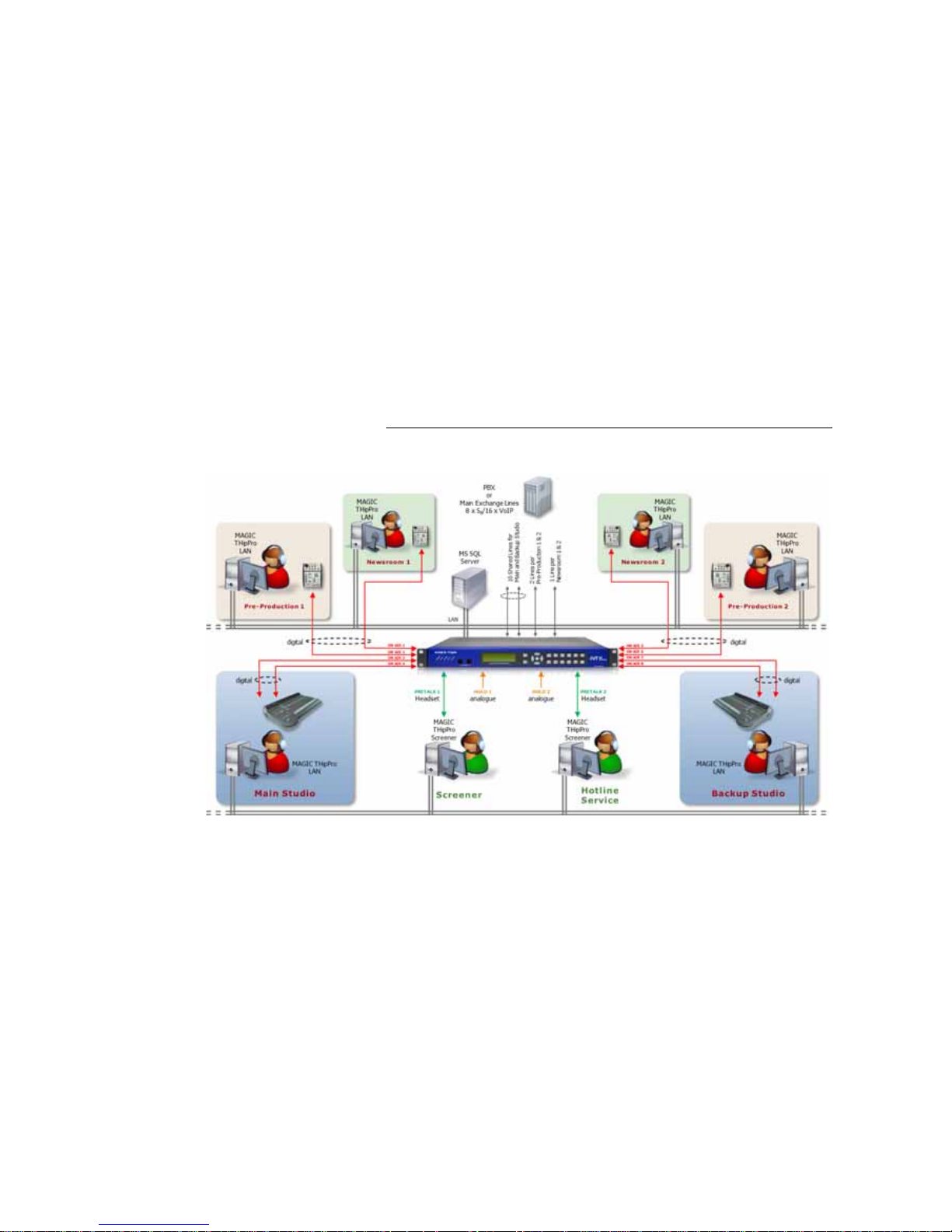
3.7.3 MAGIC THipPro with MAGIC Admin Upgrade
With the optional MAGIC THipPro Admin Upgrade, the MAGIC THipPro
Telephone Hybrid can be used for up to six studios. The caller lines can be assigned to the individual studios or they can be used by several stu dios together. In each studio only the allocated caller lines are displayed. In our example a main studio and a backup studio are established. Both can access the
shared ten caller lines and every studio has two On Air lines for a Two Faders
mode. If the main studio fails, the backup studio can go immediately On Air.
The Screener talks to the callers in Pretalk via a headset using the MAGIC
THipPro Screener Software for control. Furthermore, a workplace where
caller data is collected/updated is installed (Hotline Service) where also a
headset and the MAGIC THipPro Screener Software are in use. Besides the
main and the backup studio, there are two Pre-Productions and two News
Studios. Each of the four studios works with its own ON AIR line and uses the
MAGIC THipPro LAN Software.
Due to the MAGIC THipPro Admin Upgrade two different Hold signals,
which can be allocated to the individual studios, are possible . Alternatively,
the On Air signal or a recorded Hold signal can be used.
FIG. 9 APPLICATION WITH ADMIN UPGRADE
Page 25
PAGE 25
Interfaces
A1 INTERFACES
A1.1 MAGIC THipPro
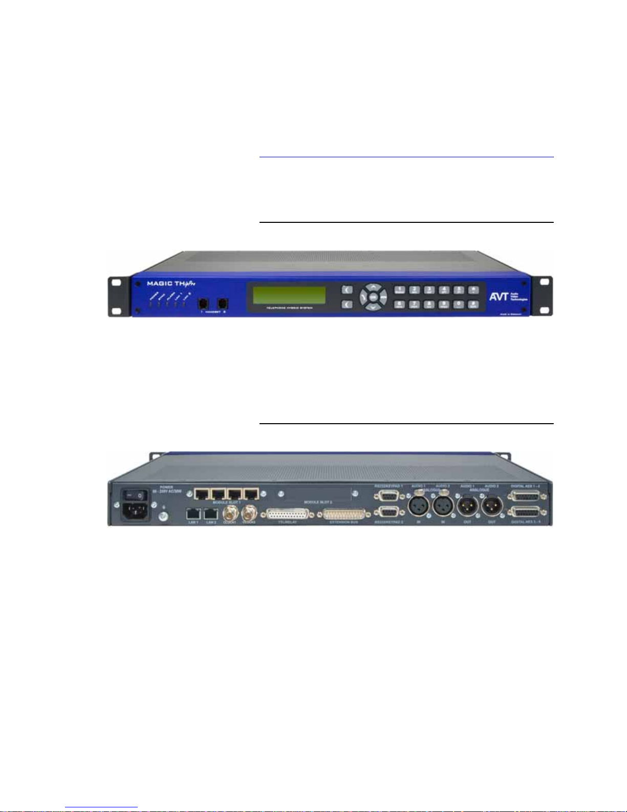
On the front side of the unit 5 LEDs for status indication and 2 Handset/Headset interfaces for PRETALK are available.
FIG. 10 FRONT VIEW OF MAGIC THIPPRO
The connectors for the interfaces are at the rear side of the unit.
FIG. 11 REAR VIEW OF MAGIC THIPPRO 8 ISDN
Page 26
PAGE 26
Interfaces
A1.2 Control and data interfaces
A1.2.1 LAN 1 and LAN 2 interfaces
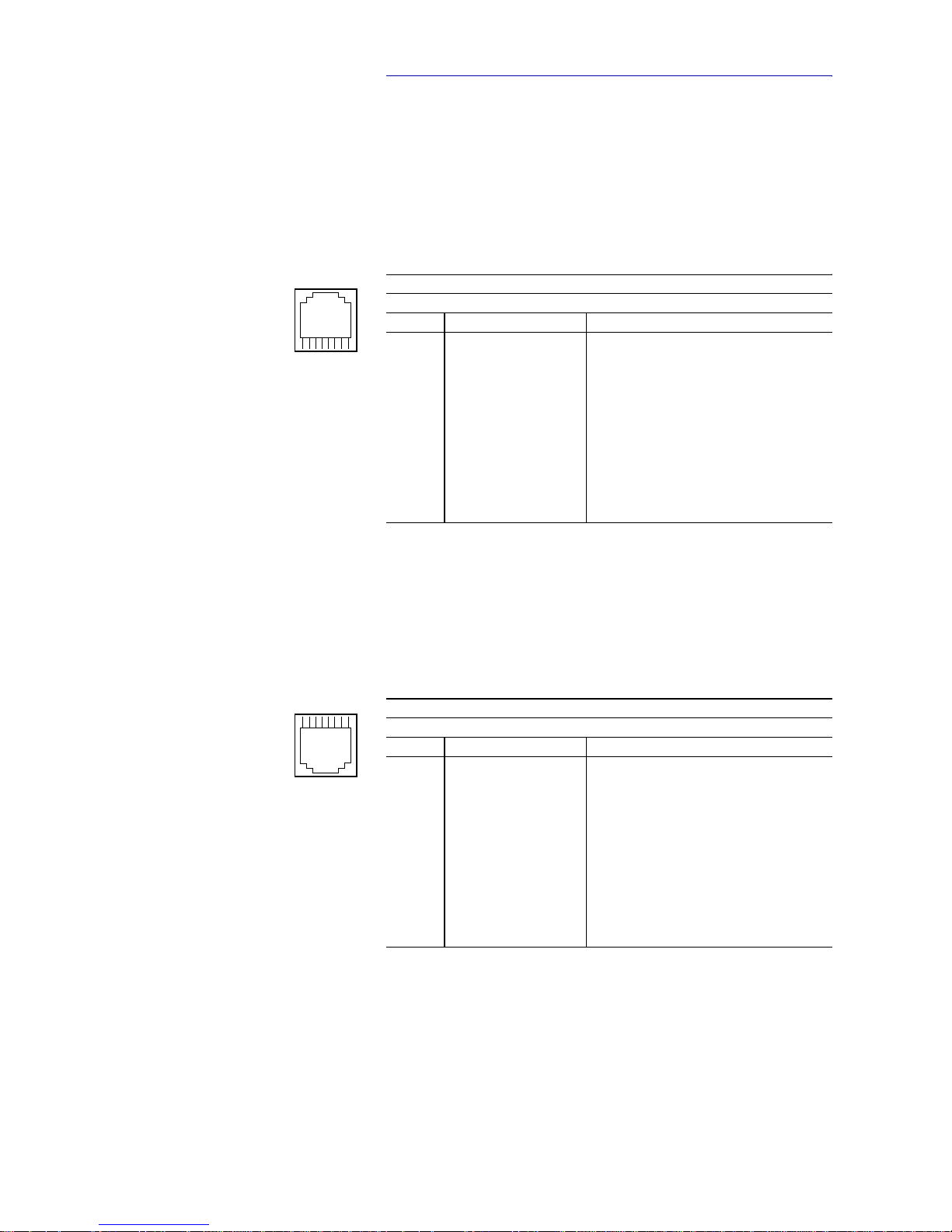
The LAN 1 and LAN 2 interfaces can be used as control interfaces. One of the
two interfaces can also be used as VoIP interface. For the LAN interfaces RJ 45
sockets are used. The pin assignment of the socket is shown in TAB. 1.
A1.2.2 ISDN Line Interfaces
MAGIC THipPro can be equipped with in maximum 2 pieces of 4 x ISDN BRI
modules. The ISDN BRI interfaces are available on RJ 45 sockets. The pin assignment is shown in TAB. 2.
TAB. 1 PIN ASSIGNMENT: LAN INTERFACES
Socket: Western (8 pin) RJ45
Pin Signal Electrical characteristics
1 TX+ Data out + Recommendation: IEEE 802.3/Ethernet
Data rate (automatic): 10BaseT (10 Mbit/s)
100BaseTX (100 MBit/s)
Recommended cable: CAT5
Maximum cable length: 100m
2 TX- Data out -
3RX+ Data in +
4not used
5not used
6RX- Data in -
7not used
8not used
TAB. 2 PIN ASSIGNMENT: BRI ISDN INTERFACES
Socket: Western (8 pin) RJ45
Pin Signal Electrical characteristics
1 not used Recommendation: I.430
Data rate: B channel: 2 x 64 kbit/s
D channel: 16 kbit/s
2not used
3TX + Data out +
4RX + Data in +
5RX - Data in -
6TX - Data out -
7not used
8not used
8
1
1
8
Page 27

PAGE 27
Interfaces
A1.2.3 POTS Line Interfaces
MAGIC THipPro can be equipped with 2 pieces of 4 x POTS modules and therefore provides 8 x POTS interfaces. The POTS interfaces are available on RJ
11 sockets. The pin assignment is shown in TAB. 3.
TAB. 3 PIN ASSIGNMENT: POTS LINE INTERFACES
Socket: Western (6 pin) RJ11
Pin Signal Electrical characteristics
1 not used Typical characteristics:
Bandwidth: 300 - 3.3 kHz
Signal to noise ratio: 45 dB
Average level: -9 dBm (275 mV)
Impedance: 600 ohms
DC voltage: 48 V (±6 V typ)
DC current: 20-26 mA (typ)
Ringing voltage 90 Vrms
Ringing frequency: 20 Hz (2 sec on, 4 sec off)
2not used
3TEL LINE +
4TEL LINE -
5not used
6not used
16
Page 28

PAGE 28
Interfaces
A1.2.4 TTL/RELAY interface
The TTL/Relay interface is realised as a 25-pin socket. It provides 8 TTL inputs or outputs and 8 Relay contacts. The pin assignment of the socket is
shown in TAB. 4.
NO = Normally Open
A1.2.5 RS232/Keypad Interfaces
Not in use.
A1.2.6 Extension Bus
Not in use.
TAB. 4 PIN ASSIGNMENT: TTL/RELAY INTERFACE
Socket: SUB-D 25 pin
Pin Signal Direction Electrical characteristics
1 TTL 1 input/output TTL interface:
Capacity of the TTL outputs:
Maximum voltage: 3.3V
Maximum current: 10mA
Relay interface:
Capacity of the relays:
Maximum voltage: 48V
Maximum current: 200mA
2 TTL 2 input/output
3 TTL 3 input/output
4 TTL 4 input/output
5 TTL 5 input/output
6 TTL 6 input/output
7 TTL 7 input/output
8 TTL 8 input/output
9 RELAY 4 (B) output, NO
10 RELAY 5 (B) output, NO
11 RELAY 6 (B) output, NO
12 RELAY 7 (B) output, NO
13 RELAY 8 (B) output, NO
14 RELAY 1 (A) output, NO
15 RELAY 1 (B) output, NO
16 GND
17 RELAY 2 (A) output, NO
18 RELAY 2 (B) output, NO
19 RELAY 3 (A) output, NO
20 RELAY 3 (B) output, NO
21 RELAY 4 (A) output, NO
22 RELAY 5 (A) output, NO
23 RELAY 6 (A) output, NO
24 RELAY 7 (A) output, NO
25 RELAY 8 (A) output, NO
1
13
14
25
Page 29
PAGE 29
Interfaces
A1.3 Audio interfaces
A1.3.1 Handset/Headset Interfaces
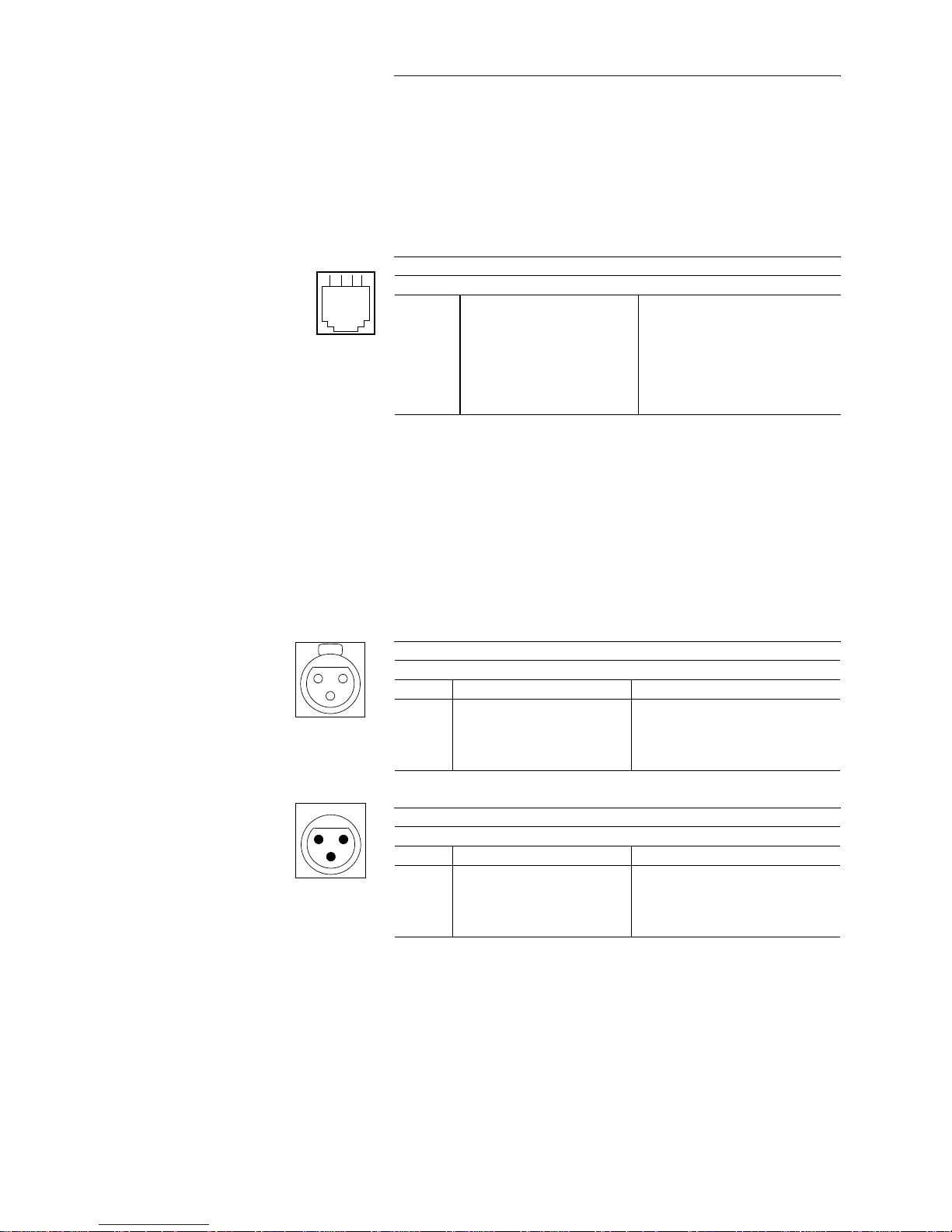
Two Handset/Headset interfaces are available at the front side of the MAGIC
THipPro. The pin assignments of the RJ10 connectors are shown in TAB. 5.
A1.3.2 Analogue Audio interfaces
MAGIC THipPro provides two analogue Audio (Audio 1, Audio 2) inputs
and outputs.
For the inputs XRL sockets and for the outputs XLR plugs are available. The
pin assignments of the sockets and connectors are shown in TAB. 6 and
TAB. 7.
TAB. 5 HANDSET INTERFACE
Socket: Western (4 pin) RJ10
Pin Signal Electrical characteristics
1 HANDSET IN a/+5V phantom power Microphone:
Impedance: ~ 2 kOhm
Sensitivity: ~ -60 dB @ 1-kHz
Telephone receiver:
Impedance: ~150 Ohm
Sensitivity: ~ 97dB @ 1-kHz
2 HANDSET OUT b (GND)
3HANDSET OUT a
4HANDSET IN b
TAB. 6 ANALOGUE AUDIO INPUT
Socket: 3 pin XLR
Pin Signal Description
1 GND Ground
+
-
2A
3B
TAB. 7 ANALOGUE AUDIO OUTPUT
Connector: 3 pin XLR
Pin Signal Descriptions
1 GND Ground
+
-
2A
3B
14
Push
12
3
2
1
3
Page 30
PAGE 30
Interfaces
A1.3.3 Digital AES/EBU Audio Interfaces
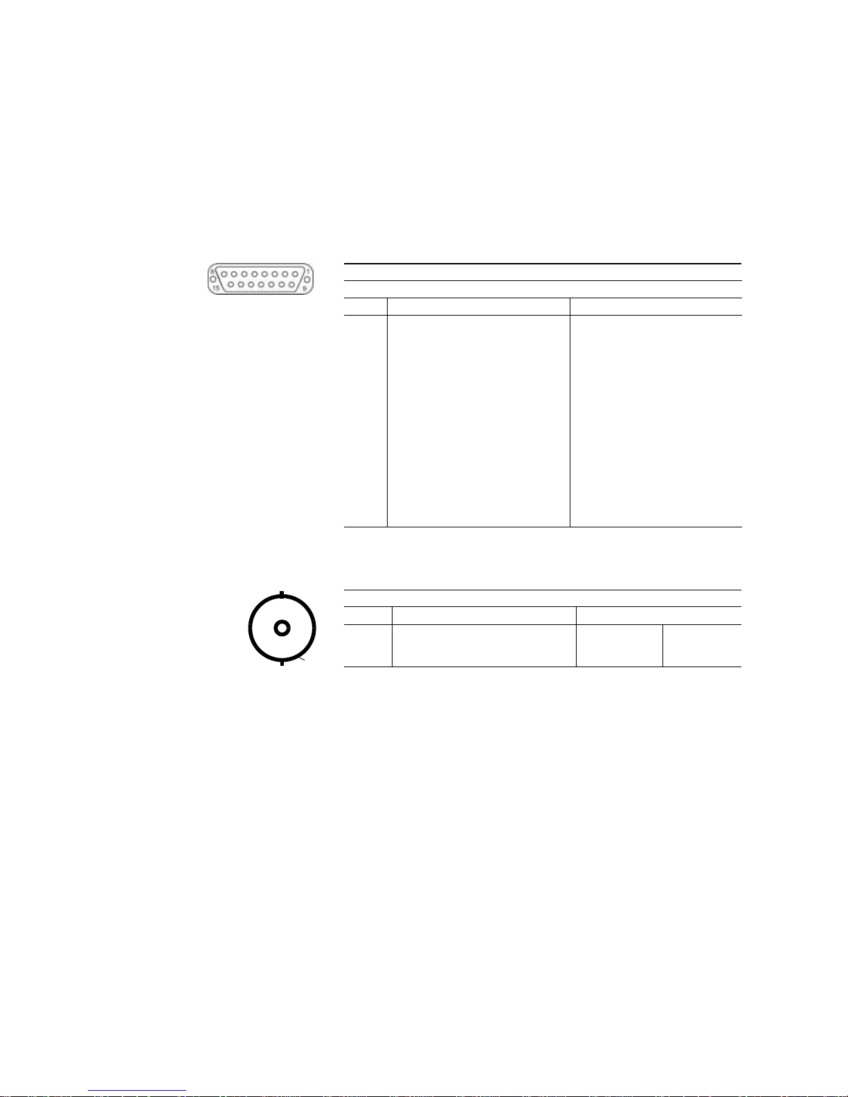
MAGIC THipPro provides eight digital Audio inputs and outputs available
on four physical AES/EBU interfaces.
Two 15-pin Sub-D sockets provide the digital AES/EBU interfaces. The BNC
socket CLOCK 1 can be used to insert an external AES/EBU clock or to receive
an AES/EBU clock . The CLOCK 2 interface is not in use.
As an option adapter cables with XLR connectors can be provided. The pin assignment of the 15-pin Sub-D sockets are shown in TAB.8. The pin assignment of the BNC socket is described in TAB. 9.
TAB. 8 DIGITAL AUDIO INTERFACES AES/EBU 1-2 AND AES/EBU 3-4
Socket: SUB-D 15 pin
Pin Signal Description
1AES 1 IN +
2AES 1 IN -
3AES 2 IN +
4AES 2 IN -
5AES 1 OUT +
6AES 1 OUT -
7AES 2 OUT +
8AES 2 OUT -
9GND
10 ... 15 GND
TAB. 9 WORD CLOCK, BNC SOCKET “CLOCK 1“
Pin Signal Electrical characteristics
1 CLOCK IN/OUT Amplitude: 0,5 to 1,9 Vop
2 GND Impedance: 75 Ohm unsym.
2
1
Page 31

PAGE 31
Technical Data
A2 TECHNICAL DATA MAGIC THIPPRO
C
ODING ALGORITHMS
– G.711 3,1-kHz (Telephone algorithm)
– G.722 (with HD Voice Upgrade in VoIP mode)
L
INE INTERFACES
:
–ISDN 8/16 version
–4/8 x S
0
–2 x LAN
– POTS version
–8 x POTS
–2 x LAN
– VoIP 8/16 version
–2 x LAN
P
RETALK INTERFACES
– Handset/Headset interface
–2 x HANDSET/HEADSET
C
ONTROL INTERFACES
–2 x LAN
– TTL/RELAY
–8 x Relay
– 8 x TTL Input/Output
A
UDIO INTERFACES
Analogue Audio 1/2:
– Electronically balanced input XLR female
– Electronically balanced input XLR male
Page 32

PAGE 32
Technical Data
– Impedance Input: > 25 kΩ
Output: < 50 Ω
– Frequency response 50 Hz ... 3400 Hz
Digital Audio AES/EBU:
– Format IEC-958 AES/EBU Professional
– Electronically balanced input 15-pin SUB-D female
– Electronically balanced output 15-pin SUB-Dfemale
– Impedance Input: 110 Ω
Output: 110 Ω
– Separate Sample Rate Converter for Inputs
Handset/Headset:
– Electronically balanced input RJ10 socket
– Electronically balanced output RJ10 socket
S
IGNAL PROCESSING
– AGC per channel, configurable
– Level adjustment control during connection: -16 dB ... +16 dB
– Echo Canceller per channel
– Expander per channel, configurable
D
ISPLAY
- graphical resolution 160 x 32 Pixel
- illuminated (can be switched off)
D
IMENSIONS
H x W x D
– 44,5 x 434 x 252 mm
W
EIGHT
– ca. 3,7 kg
Page 33

PAGE 33
Technical Data
A
DDITIONAL INFORMATION
EMC
– EN 55103
Electric safety
– EN 60950
Temperature Range
–+5
°
C to 45 °C
Relative humidity
– 5% is 85%
Page 34

PAGE 34
General
A3 GENERAL
A3.1 Order numbers
MAGIC THipPro 8 VoIP 802050
MAGIC THipPro 8 POTS 802051
MAGIC THipPro 8 ISDN 802052
MAGIC THipPro 16 VoIP 802053
MAGIC THipPro 16 ISDN 802055
Accessories
MAGIC THipPro Telephone Handset 490180
with Handset Rest
MAGIC THipPro Telephone Headset 490181
Mono Aural
MAGIC THipPro Telephone Headset 490182
Bin Aural
MAGIC THipPro Volume Adapter 490178
Cables
AES/EBU/CLK Adapter Cable 490183
Software Options
MAGIC THipPro LAN Software licence 430401
MAGIC THipPro Screener Software licence 430402
MAGIC THipPro Admin Upgrade 430404
MAGIC THipPro DTMF Tone Analyzer 430405
Upgrade
Pretalk Streaming Ugrade 430464
System Upgrades
MAGIC THipPro 8 ISDN/POTS
-> 8 VoIP channels Upgrade 802057
MAGIC THipPro 16 ISDN/POTS
-> 16 VoIP channels Upgrade 802058
Page 35

PAGE 35
General
MAGIC THipPro 8 ISDN
-> 16 ISDN channels Upgrade 802059
MAGIC THipPro 8 VoIP
-> 16 VoIP channels Upgrade 802060
MAGIC THipPro 8 ISDN/POTS
-> 16VoIP channels Upgrade 802061
Page 36

PAGE 36
General
A3.2 Scope of delivery
– MAGIC THipPro Telephone Hybrid
– CD Windows PC Software
– External Power Supply Adapter
Input: 100 - 240V/24W, 50 - 60 Hz
Output: 12V
– Self adhesive feet
– 19’’ Mounting brackets
–Manual
A3.3 Declaration of conformity
The declaration of conformity you will find at the end of this manual.
Page 37

PAGE 37
Service Information
A4 SERVICE INFORMATION
A4.1 Software Updates
On our homepage you can download software updates for free. Go to
http://www.avt-nbg.de
and select Download - Software.
A4.2 Support
You can contact our Support Hotline during the normal office hours between
09.00h - 17.00h (GMT+1) under the following telephone number:
+49 911 5271 160
or via E-Mail under
To deal with your problem efficiently please note the factory number of the
unit as well as the software version that you use.
A4.3 Repairs
If, contrary to expectations, your unit is defective please fill in the attached
status report and send the unit to the following address:
AVT Audio Video Technologies GmbH
- Repairs Nordostpark 12
D-90411 Nuernberg
Germany
Page 38

PAGE 38
Service Information
Page 39

Name des Anbieters: AVT Audio Video Technologies GmbH
Supplier’s name:
Anschrift des Anbieters: Nordostpark 12
Supplier’s address D-90411 Nürnberg
erklärt, daß das Produkt
declares, that the product
Produktname(n): MAGIC THipPro 8 VoIP Telephone Hybrid 802050
Product name(s): MAGIC THipPro 8 POTS Telephone Hybrid 802051
MAGIC THipPro 8 ISDN Telephone Hybrid 802052
MAGIC THipPro 16 VoIP Telephone Hybrid 802053
MAGIC THipPro 16 ISDN Telephone Hybrid 802055
mit den Vorschriften folgender Europäischer Richtlinien übereinstimmt:
conforms to the standards of the following European directives:
Nummer/Text: EN 60950 A4 Gerätesicherheit
Number/title:
Die Übereinstimmung wird nachgewiesen durch vollständige Einhaltung folgender Normen:
The conformity is evidenced by strictly meeting the following standards:
Harmonisierte Normen: EN 55022, EN 55024,
Harmonized Standards: EN 300386,
FCC Part 15 B
Ort, Datum: Nürnberg, 20.02.2013
Place, date:
Name(n): Wilfried Hecht
Name:
Rechtsverbindliche Unterschrift(en):
Legally binding signatures:
Telefon: +49 911 5271-0
Phone:
Diese Erklärung beinhaltet keine Zusicherung von Eigenschaften.
This declaration includes no warranty of properties.
Die Sicherheitshinweise der mitgelieferten Produktdokumentation sind zu beachten.
The safety instructions specified in the product documentation delivered must be observed.
Declaration of Conformity
-Konformität
DECLARATION OF CONFORMITY
Page 40

 Loading...