

Page 1

MAGIC
ISDN
Audio Transmission System
Hardware Description
Page 2

Page 3

MAGIC ISDN
AUDIO TRANSMISSION SYSTEM AS PER
ISO/MPEG STANDARD LAYER II/III AND
ITU-RECOMMENDATIONS G.722, G.728
AND G.711
HARDWARE DESCRIPTION
Page 4

Page 5

Acknowledgements
LabWindows is a reg is ter ed tra de mark
of National Instruments
AVT Audio Video Technologies GmbH
Rathsbergstrasse 17
D-90411 Nuernberg
Telefon (0911) 5271-0
Telefax (0911) 5271-100
Internet: www.avt-nbg.de
Email: [email protected]
Printed in Germany, April 1997
AVT Au dio Video Te chnologies
All rights reserved. Reproduction in whole
or in parts is prohibited without the written
consent of the copyright owner.
The information contained in this
publication is accurate to the best of our
knowledge. However, we disclaim any
liability resulting from the use of this
information and reserve the right to make
changes without notice.
Order number
040 7448 33964 6 (0 6- 0 0)
HW MAGIC ISDN
Page 6

Page 7

CONTENT
CONTENT
1 QUICK INTRODUCTION 11
1.1 Transmission of a stereo signal via 2 ISDN B channels (PC control) 12
1.1.1 Connection of the components 12
1.1.2 Putting into operation 13
1.1.3 Setting up the call 13
1.1.4 General advice on dialing using the PC software 14
1.2 Transmission of a stereo signal via two ISDN B channels 15
1.2.1 Connection of the components 15
1.2.2 Putting into operation 15
1.2.3 Setting up a connection using a stored calling number 16
1.2.4 Setting up a manually dialled call 18
1.2.5 General advice on dialing using the Display and Keypad 18
1.3 Factory settings 20
1.3.1 Interface Unit factory settings 20
1.3.2 Codec factory settings 20
2 SYSTEM DESCRIPTION 21
2.1 General 21
2.2 System concept 22
2.3 Construction of MAGIC ISDN Audio Codec 22
2.3.1 Additional options for transmission at higher data rates 23
2.4 Interface Unit 24
2.5 The ‘Layer II/III Audio Codec ’ 27
2.6 The ‘Layer II/III Audio Decoder’ 28
2.7 The ‘ Audio Layer II/III Analog I’ Board 29
2.8 Example of a MAGIC system connection 30
3 PUTTING THE MAGIC SYSTEM INTO OPERATION 31
3.1 Construction of the MAGIC Audio Codec 31
3.2 Selection of the network interface 32
3.3 Connection to the data network 32
3.4 Applications with MAGIC ISDN and MAGIC Systems 33
3.4.1 Generel Transmisssion applications in different qualities 33
3.4.2 Transmission via an X.21 channel at up to 1920-kbit/s 34
3.4.3 Transmission of an audio signal with the signalling switched off35
3.4.4 Audio transmission via ISDN 36
3.5 Connection to the mains voltage 37
3.6 Opening the Device 37
3.7 Setting the centre-tap earth for the analogue audio inputs 38
Page 8

CONTENT
3.8 Switching on the system 38
4 OPERATION WITH THE OPERATOR PANEL 39
4.1 Menu tree 40
4.2 The main menu 41
4.3 Submenus 42
4.4 Entering the commands 43
4.5 Programming example: Storing calling numbers 43
4.6 Programming example: setting the RS232C for control via a PC 45
ANNEX 1 TECHNICAL DATA 49
A1.1 Interface Unit with variable network access 49
A1.2 Audio Codec Layer II / III 50
A1.3 Analogue Unit for Audio Codec Layer II / III 51
A1.4 Power supply 52
A1.5 Dimensions 52
A1.6 Miscellaneous 52
A1.7 Additional features 52
A1.8 Ordering information 53
ANNEX 2 INTERFACES 55
A2.1 Extension Bus 55
A2.2 Audio interfaces 56
A2.2.1 AES/EBU interface 56
A2.2.2 Analogue Audio interface 56
A2.3 Network interfaces 56
A2.3.1 So interfaces 56
A2.3.2 X.21 interfaces 56
A2.4 Sampling clock output 58
A2.5 Data interfaces 58
A2.5.1 HSD interface 58
A2.5.2 LSD interface 58
A2.5.3 Additional Data 59
A2.6 Operator interfaces 59
A2.6.1 RS232C and RS232 AUX interfaces 59
A2.6.2 RS485 bus interface 60
A2.6.3 User I/O interface 60
ANNEX 3 USER I/O INTERFACE APPLICATIONS 63
A3.1 Logic level transfer Mode 63
A3.2 Printer mode 64
Page 9

CONTENT
ANNEX 4 LIST OF THE ALARMS 65
Page 10

CONTENT
Page 11

PAGE 1 1
QUICK INTRODUCTION
1 QUICK INTRODUCTION
This chapter contains the most important steps required for the transmission
of an analogue stereo signa l via ISDN. SECTION 1.1 describes the procedure
to be used if a control PC has been connected to the MAGIC system.
SECTION 1.2 explains the steps for contro l with the oper ator pa nel (wi thout a
PC). With the exception of the connection between PC and MAGIC system,
the installation is identical in both cases.
With the respective page, carry out the described steps point by point. P lease
ensure that the installation is also carried out at the remote e nd. The system s
at both ends do not have to be controlled by a PC.
The call set up can be from eithe r side. Th e called equipment accepts the call
automatically .
If the transmission should be in only on e direction, then only one signal sour ce
and one signal sink are used.
The factory settings are listed at the end of the chapter.
Page 12
PAGE 1 2
QUICK INTRODUCTION
1.1 Transmission of a stereo signal via 2 ISDN B channels (PC control)
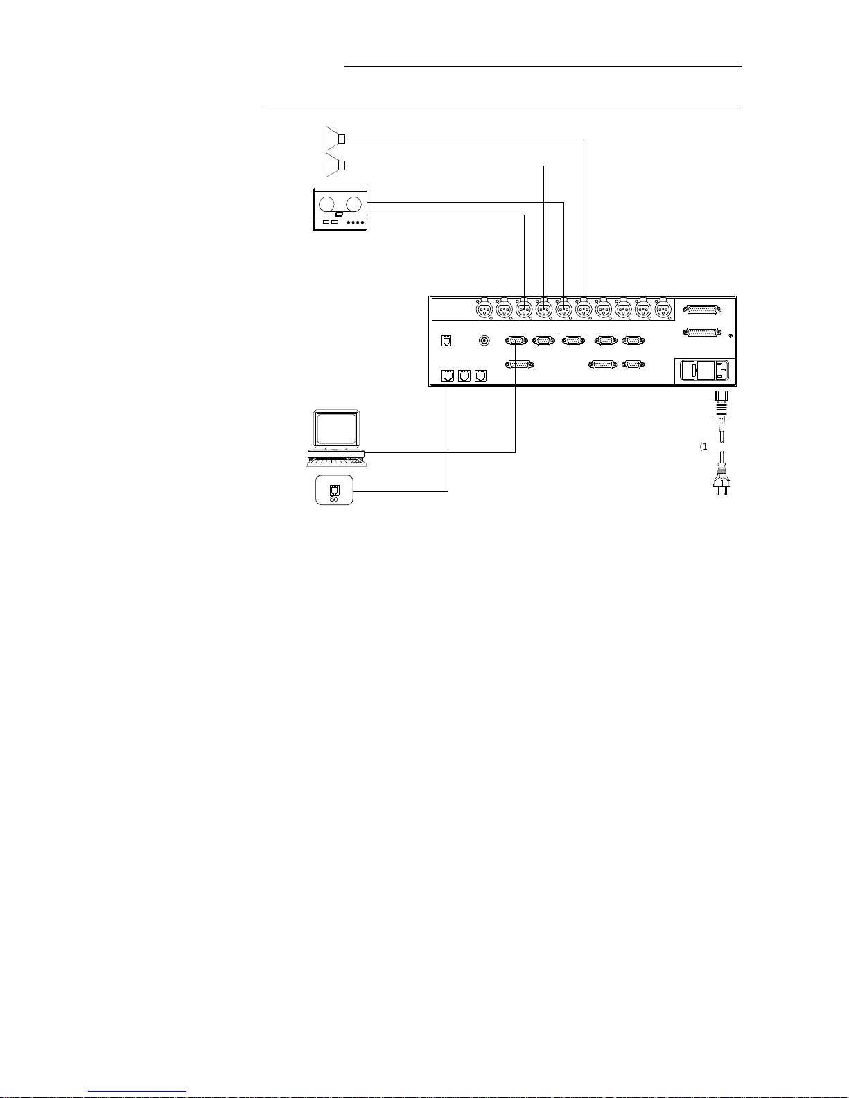
FIGURE 1.1 THESE CABLES MUST BE CONNECTED
1.1.1 Connection of the components
(1) Mains cable: Use the mains cable provided.
(2) PC connection: Connect a free interface of the PC with the socket on
the MAGIC system labelled
RS232 C
.
(3) Connect the MAGIC ISDN to the S0 socket(s).
(4) Connect the audio signal
source
(transmit sound) to the sockets #1
(left) and #3 (right) of
slot 2
.
(5) Connect the audio signal
sink
(receive sound) to the sockets #2 (left)
and #4(right) of
slot 2
.
Transmit sound, right analogue
Transmit sound, left analogue
Received sound, right a nalogue
Received sound, left an alogue
MAGIC control
RS232C
Line X.21 HSD LSD
Additional Data
Slot 2 Slot 3RS232-AuxRS485
Extension Bus
TTL User I/O
Handset
ISDN 1 ISDN 2 ISDN 3
Clock Out
CMD In CMD Out Left In Left Out Right OutRight In Aux In Aux OutDig In Dig Out
Dig In Dig Out
Slot 2 Slot 3
ISDN
5Q
(1)
(2)
(3)
(4)
(5)
Page 13

PAG E 1 3
QUICK INTRODUCTION
1.1.2 Putting into operation
(1) Switch on the MAGIC system (mains switch at front)
(2) Switch on the PC.
(3) Install the PC operating software (remember to make a backup copy!):
– Insert disk
– Install the software on the hard disk by typing
CKPUVCNN
– When the required directory is requested, simply press RETURN
and the software is installed in the default directory which is shown
in brackets.
(4) Start the program :
OCIAKUFP
or
OCIAO
, depending on which version is
required. In the lower right corner of the screen, the message PCCONN indicates that the connection between PC and MAGIC system
is in order.
FIGURE 1.2 AFTER SWITCHING ON, THE SYSTEM TAKES APPROXIMATELY 60 SECONDS T O BOOT UP.
DURING THIS TIME THE MESSAGE PC-DROP IS DISPLAYED IN T HE LOWER RIGHT CORNER
OF THE PC SCREEN.
(5) To avoid faulty i nstallation, first of all l oad the fa ctory setting s: click with
the mouse on the word CONF IG in the top row of the scr een. Under the
pull-down menu which opens, move the mouse pointer to
FACTORY SETTINGS and click on this. The settings are now loaded.
1.1.3 Setting up the call
(1) To set up the charge display, click on the CHARGES key. In the panel
which opens you can enter the cur rent CH ARGE FACTOR. Thi s fa ctor
is the cost for each charge unit. Additionally, under CURRENCY, the
currency to be d is played can be e nter ed. Th e se ttings are immediately
stored in non-volatile memory.
REMARK
With the 1TR6 national protocol, the charging impulses are
normally provided . With DSS-1 p rotoc ol, these must be requested.
(2) Change to the LINE pa nel a nd se lect yo ur ISDN protocol. The settings
are immediately stored in non-volatile memory.
(3) Activate the CALL panel: click the word CALL in the top row of the
screen with the mouse.
(4) If the MAGIC System is conne cted thr oug h a PABX, the prefi x nu mber
for the outside line can be entered under PREFIX NO.
(5) Open the window for the entry of numbers: Click the MANUAL CALL
key in the right part of the screen.
(6) Enter the calling numbers:
– AREA CODE: Enter the (country and) area codes
– NUMBER 1: Calling number of the first B channel
– NUMBER 2: Calling number of the second B channel
(7) Set up the call: Click the CALL key with the mouse
The remote side must al so be operational an d have the factory settin gs
loaded.
Page 14

PAGE 1 4
QUICK INTRODUCTION
(8) Check the connection: The MAIN panel appears on the screen. The
status of the interfaces a nd the diall ed number i s displayed here (CONNECT = connection made) and the number dialled.
Transmit signal
Start the audio signal sources and sinks at both en ds of the transmission p ath.
Disconnect the call
Click the word DISC! in the top line of the screen. The call is cleared down.
1.1.4 General advice on dialing using the PC software
(1) When a direct line is use d, the prefix number to obtain an e xchange line
through a P ABX can be suppresse d if the calling number is pr eceeded
with a “-” sign. This is important if the call is to be set up within the
PABX. The minus sign should only be added to the first number. This
display can be reached when entering the calling number, by pressing
the key.
(2) If you want to se t up a norm al telephone con nection, it must be ensured
that this is done using the so-called Telephone Service Indicator. The
selection of the Telephone Service Indicator occurs when a “T” sign is
added before the first entered calling number. Without the “T” sign the
“Data” Service Indicator is always dialled.
Page 15
PAG E 1 5
QUICK INTRODUCTION
1.2 Transmission of a stereo signal via two ISDN B channels
(control with operator panel)
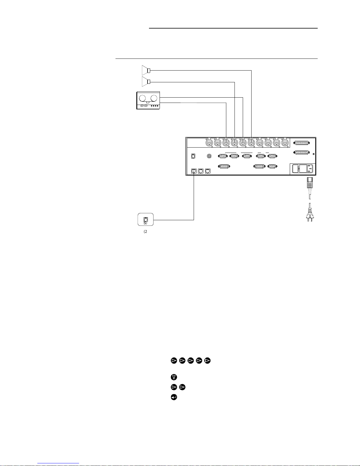
FIGURE 1.3 THESE CABLES MUST BE CONNECTED
1.2.1 Connection of the components
(1) Mains cable: Use the mains cable provided.
(2) Connect the MAGIC ISDN to the S0 socket(s).
(3) Connect the audio signal
source
(transmit sound) to the sockets #1
(left) and #3 (right) of
slot 2
.
(4) Connect the audio signal
sink
(receive sound) to the sockets #2 (left)
and #4(right) of
slot 2
.
1.2.2 Putting into operation
(1) Switch on the MAGIC system (mains switch at front)
(2) Load the MAGIC ISDN factory settings:
– : Press “right” cursor five times (* now next to
MEM)
– : Press “down” cursor once
– : Press “right” cursor twice (* is now at INIT)
– : Press Enter. The factory settings are loaded.
(3) Set up the call: this can be done by choosing a programmed calling
number (see SECTION 1.2.3) or b y directly ente ring the calling number
(see SECTION 1.2.3).
Transmit sound, right analogue
Transmit sound, left analogue
Receive sound, right analogue
Receive soun d, l eft analogue
RS232C
Line X. 21 HSD LSD
Additional Data
Slot 2 Slot 3RS232- A uxRS485
Extension Bus
TTL User I/O
Handset
ISDN 1 ISDN 2 ISDN 3
Clock Out
CMD In CMD Out Left In Left Out Right OutRight In Aux In Aux OutDig In Dig Out
Dig In Dig Out
Slot 2 Slot 3
ISDN
5Q
(2)
(1)
(3)
(4)
Page 16
PAGE 1 6
QUICK INTRODUCTION
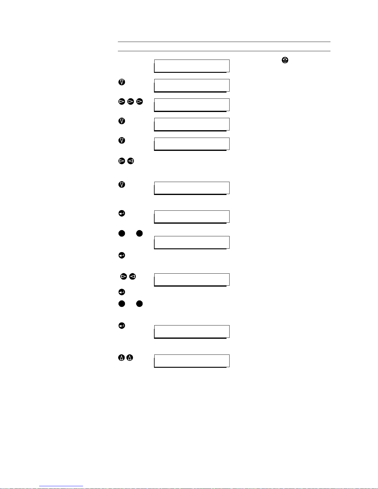
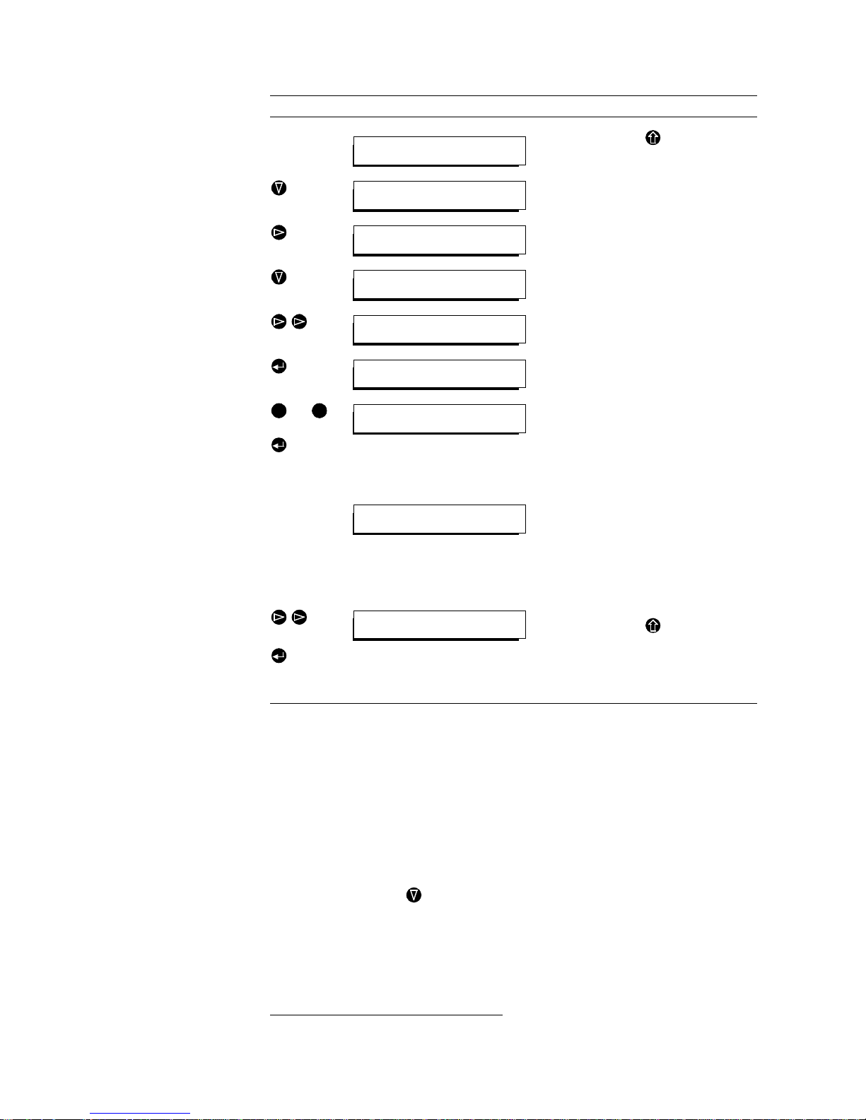
1.2.3 Setting up a connection using a stored calling number
Keys Display Remarks
Main men u
Starting point. If another menu is dis pl ayed,
press the Escape key to call up the main
menu.
Press the “down” cursor key to display the
CALL
submenu.
With the “right” cursor key, select the
SET
menu item.
Press the “down” cursor key to display the
SET
submenu.
With the “down” cu rsor key, sel ect the
NRS
menu item.
)
With the “right” and “left” cursor keys, select
the required service:
DATA
: Call with Data Indicator (Default 1..6B)
TEL:
Call with Telephone Indicator (1B)
Press the “down” cursor key to display the
DATA
submenu.
Enter the (country and) area code
Display the
AREA
submenu by pressing
Enter.
bis
Enter the count ry and/or area code with th e
keys 0 to 9.
Confirm the number wit h Enter . The submenu
NRS
is then automatically displayed.
Enter the calling numbers
( )
With the “right” and “left” cursor keys, select
the requi r e d nu m ber from N1 to N6. Display
the submenu with Enter.
bis
Enter the calli ng number without coun try or
area code.
Confirm the entered number with Enter. The
submenu
NRS
is automatically called up.
To enter further calling numbers, select the
number from N1 to N6 and proc ee d as desc ribed above.
Enter only the first two numbers!
With the “up” cur sor ke y, display the
SET
sub-
menu.
*CALL RD DIS CFG SYS MEM
Call menu
*NAME MAN CONN SET ANSW
Call by name
NAME MAN CONN *SET ANSW
Set call-by-name memory
*NRS MODE SAVE ERASE
Set call numbers
*DATA TEL
Set data call
*AREA N1 N2 N3 N4 N5 N6
Area code
Enter area code:
0911
0 9
*AREA N1 N2 N3 N4 N5 N6
Area code
Enter phone number:
9952705
0 9
AREA *N1 N2 N3 N4 N5 N6
Number 1
*NRS MODE SAVE ERASE
Set call numbers
Page 17
PAG E 1 7
QUICK INTRODUCTION
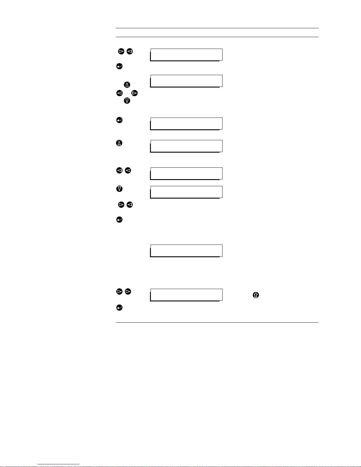
Saving
( )
With the “right” and “left” cursor keys, select
the
SAVE menu
.
Select the
SAVE
submenu with the E nter key.
Enter the name ass ociated with the c alling
number.
The selection of lett ers and other character s is
by repeated pressing of the “up” and “down”
cursor keys.
For a name with more than one character ,
change the c ursor posi tion with th e “right” and
“left” cursor keys.
Confirm the configuration name with Enter.
The successful stora ge is indi cated on the di splay. Press any key to automatically call up the
SET
submenu.
With the “up” curs or key, activate the
CALL
submenu.
Set up the call
Select the
NAME
menu item with t he “left” and
“right” cursor keys.
( )
Press the “down” cursor key to disp l ay the
NAME
submenu.
Select the required name with the “left” and
“right” cursor keys and confirm with Enter. A
call is set up to the number stored under this
name.
The remote end must also be operational an d have the factory sett ings loaded.
Check the connecti on
In the second lin e of the dis pl ay,
Connect 2B
should appear.
Transmit the signal
Start the audio s ignal sources and sin ks at both ends of the transmission route.
Disconnect the call
Main menu. From any other menu, press the
Escape key to call up the main menu.
Press the “right” cursor key to select the DISC
menu item.
Confirm with the Enter key.
The connection is cleared down.
Keys Display Remarks
NRS MODE *SAVE ERASE
Save call-by-name data?
Enter call name:
TESTLOOP
Call data stored!
Press any key!
NAME MAN CONN *SET ANSW
Set call-by-name memory
*NAME MAN CONN SET ANSW
Call by name
Select call data:
TESTLOOP
*CALL RD DIS CFG SYS MEM
Connect 2B
CALL RD *DIS CFG SYS MEM
Disconnect line
Page 18
PAGE 1 8
QUICK INTRODUCTION
1.2.4 Setting up a manually dialled call
1.2.5 General advice on dialing using the Display and Keypad
(1) The exchange line number ca n onl y be en tere d using th e PC sof tware
(important only for PABXs).
1
(2) When a direct line is use d, the prefix number to obtain an e xchange line
through a P ABX can be suppresse d if the calling number is pr eceeded
with a “-” sign. This is important if the call is to be set up within the
PABX. The minus sign should only be added to the first number. This
display can be reached when entering the calling number, by pressing
the key.
(3) The setting up of the chargin g factor and the curren cy for a charge unit
is also only possible using the PC software.
1
(4) All calling numbers can be ente red by the PC software and transferre d
afterwards to the MAGIC ISDN System.
Keys Display Remarks
Main men u
Starting point. If another menu is dis pl ayed,
press the Escape key to call up the main
menu.
Press the “down” cursor key to display the
CALL
submenu.
With the “right” cursor key, select the
MAN(ual)
menu item.
Press the “down” cursor key to display the
MAN(ual)
submenu.
With the “right” cursor key, select the
128k
menu item (for a 2B channel connection).
The entry of the number is reques ted by pressing Enter.
bis
Using the keys 0 to 9, enter the required number complete with country and/or area code.
Confirm the number wit h Enter. The connection will be set up immediately.
The remote end must also be operational and have the factory settings loaded.
Check the connection
In the second line of the dis play,
Connect 2B
should appear.
Transmit the signal
Start the audio signal sources and s inks at both ends of the transmission route.
Disconnect the call
Starting point. If another menu is dis pl ayed,
press the Escape key to call up the main
menu.
Press the “right” cursor key to select the DISC
menu item.
Confirm with the Enter key.
The connection is cleared down.
1 This can also be done REMOTELY by our Service, in case PC Software is not to hand.
*CALL RD DIS CFG SYS MEM
Call menu
*NAME MAN CONN SET ANSW
Call by name
NAME *MAN CONN SET ANSW
Manual call
*TEL 64k 128k
Telephone call
TEL 64k *128k
128kbit data call
Enter phone number:
0 9
Enter phone number:
09119952705
TEL 64k *128k
Connect 2B
CALL RD *DIS CFG SYS MEM
Disconnect line
Page 19
PAG E 1 9
QUICK INTRODUCTION
(5) If connections are always made to Audio Codecs from different manu-
facturers, a configuration can be stored against each calling number.
Up to 10 configurations can be stored in the MAGIC ISDN Codec and
linked to calling numbers. First of all, the requirements (e.g. for MUSICTA XI or CDQ1000) fo r the far end shoul d be stored. Follow ing the entry
of the calling number, the correct configuration can immediately be
stored with it. To do this do not store the calling number immediately it
is entered but first change to the
MODE
menu.
REMARK
The majority of Audio Codec manufacture rs use proprietar y signaling modes. If a call should fail, knowledge of the remote
end mode enables the MAGIC ISDN System to be correctly
configured.
When making a call however, one must be certain that the
equipment at bo th ends u ses the sam e signaling mode. S ince
with the majority of modes, automatic mode identification is
not possible, disconnection follows within one second when
the required signaling identification is not received.
If however, a normal telephone is called from MAGIC, this is
recognised by all modes as the recognised service indicator
preceeds the dialling.
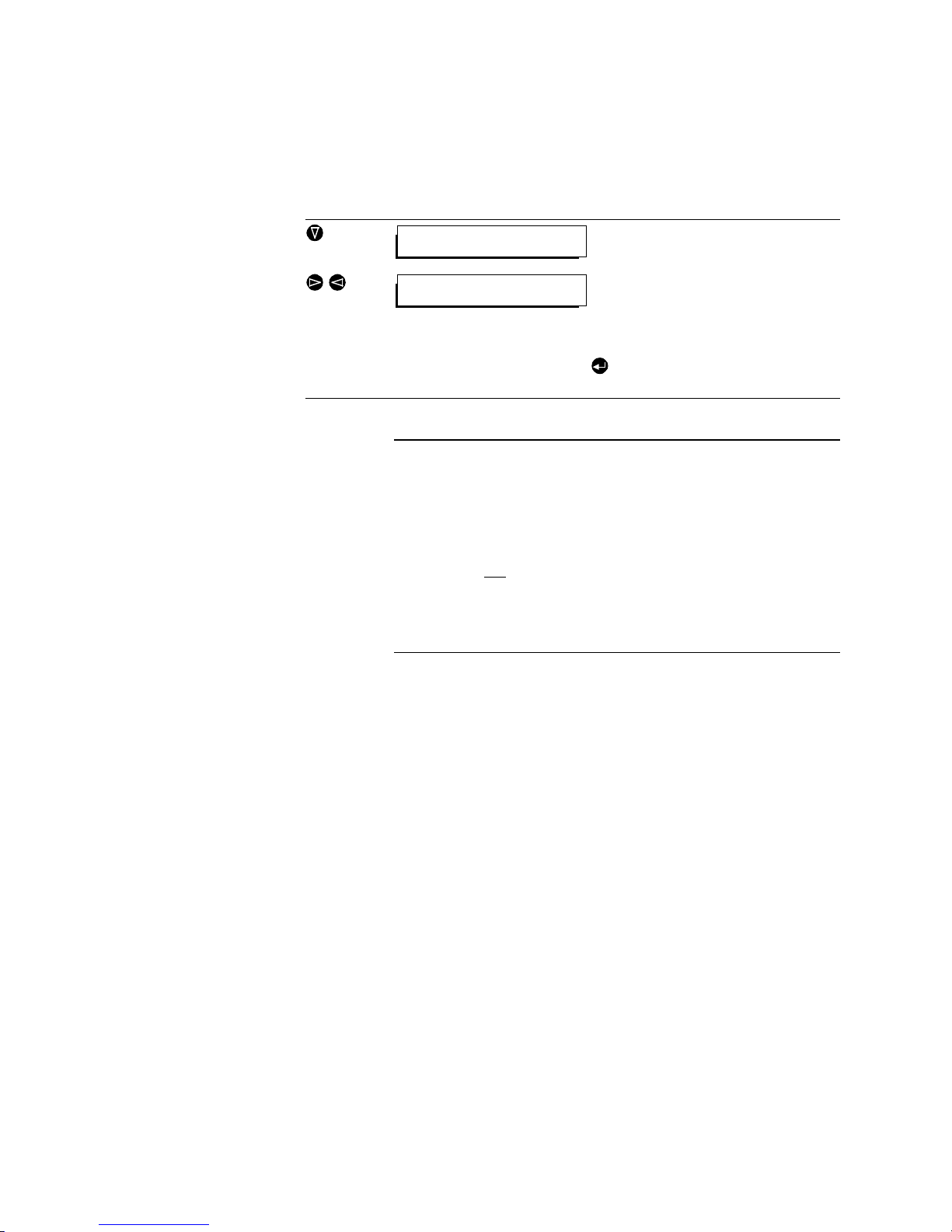
Press the “down” cursor key to disp l ay the
MODE
submenu .
)
With the “right” and “left” cursor keys, select
the required conf iguration.
The choice of c onfigurations mus t have been
stored previously. The configuration names
will then be displ ayed.
After selecting the configuration and pressing the , the number can be saved as described
above.
NRS *MODE SAVE ERASE
Set call numbers
Select configuration:
0: <<FREE>>
Page 20

PAGE 2 0
QUICK INTRODUCTION
1.3 Factory settings
1.3.1 Interface Unit factory settings
Line interface: ISDN
Clock source: External
Bit Inversion: Switched off
Call answering: Switched on
Inband signalling mode: J.52 (bidir.)
Data rate: 2∗64 kbit/s
Command channel: Switched off
LSD channel: Switched off
LSD Mode: V.24 (transparent channel)
Handshake: Switched off
HSD (X.21)-Mode: Switched off
HSD Data rate: 1∗64 kbit/s
ISDN Protocol: not set with FACT. SETTINGS
1.3.2 Codec factory settings
Encoder input: Main analog
Main output: Decoder analog
Coding Mode: Layer III
Digital output mode: Professional
Auxiliary output: Switched off
Command channel:: Normal
Input impedance: 15 kΩ
Nominal audio input level: 6 dBu
Nominal audio output level: 6 dBu
Sampling frequency: 48 kHz
Coding mode: Joint Stereo
Original signalling bit: Copy
CRC check: Switched on
Copyright indication bit: Switched off
AES/EBU CLOCK: Automatic
Additional data channel: Switched off
Additional data rate: 2400 Baud
Page 21
PAG E 2 1
SYSTEM DESCRIPTION
2 SYSTEM DESCRIPTION
2.1 General
Due to the cost advantages offered by the efficient utilisation of available
transmission capacities, low-bit-rate encoding is becoming increasingly important for the transmission of aud io signals. The MAGIC system (Multi Audio
system with Groupable Interfaces and Codecs) was developed for this reason. With the system, high-quality audio signals can be transmitted bidirectionally in CD-transparent qual ity. Its main application is the transmission of one
or more channels via ISDN, satellite or data networks.
All standardised methods of data reduction for audio signals (ITU-T G.711,
G.722, G.728, ISO/MPEG Layer II (DAB) and III) are integrated into the MAGIC system. The p rocedures which ensure secur e and synchr onous transmission also comply with international standards and recommendations (ITU-R
J.52), thus guaranteein g the future -oriented concept of th e MAGI C system as
well as its compatibility with all systems implementing these standards
REMARK
In order to be able to make full use of the functions of the
MAGIC audio system, we reco mm end that you r ead chap ters
2 and 3 first.
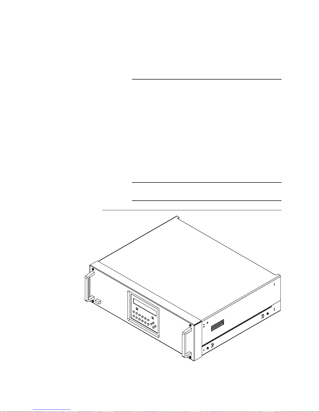
FIGURE 2.1 MAGIC ISDN UNIT
Page 22
PAGE 22
SYSTEM DESCRIPTION
2.2 System concept
Using the ISDN Codec over its X .21 interface, up to 1 0 encoded audio si gnals
can be transmitte d over a da ta network. The a dditional Code cs are connecte d
to the MAGIC ISDN system over an extension bus.
More comprehensive information on the MAGIC EXTENSION system is contained in the MAGIC BASIC System Hardware Description. The special features of the MAGIC ISDN Audio Codec are as follows.
2.3 Construction of MAGIC ISDN Audio Codec
The
/#)+% +5&0
unit consists of a two-part housing, a back-plane, the power
supply, the front keypad with two-line display and the front panel.
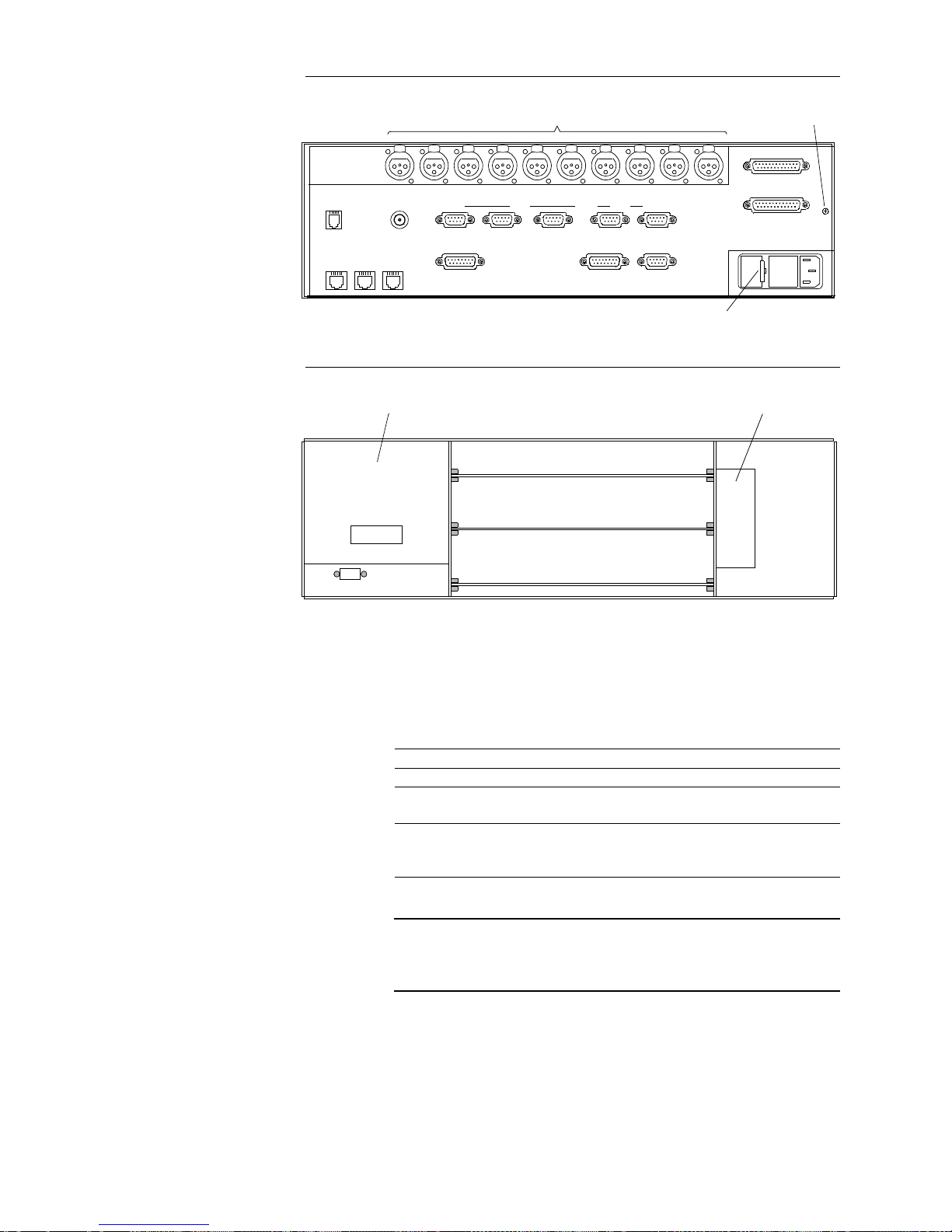
FIGURE 2.1shows the closed housing of the
+5&0
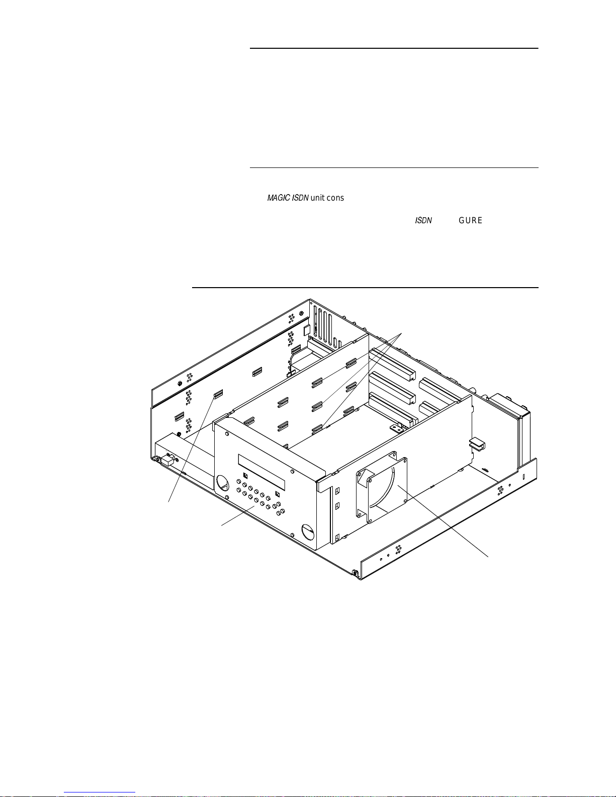
unit, FIGURE 2.2 shows the
open view of the e quipment. FIGURE 2.3 is a rear view of the system with th e
various connectors. FIGURE 2.4 is a view of the system with the front panel
and display removed. Shown here are board mounting slots 1 to 3. These
mouting slots can be variously equipped.
FIGURE 2.2 VIEW OF THE OPENED HOUSING OF THE MAGIC ISDN SYSTEM
Fans
Front panel display wi th keypad
Slots for the plug-in units
Slot for po w er supply
Page 23
PAG E 2 3
FIGURE 2.3 REAR VIEW OF THE MAGIC SYSTEM
FIGURE 2.4 MAGIC SYSTEM WITHOUT FRONT PANEL
The following table shows the different equipping variants of the system. It
should be noted that a MAGIC ISDN unit must always be equipped with an
Interface Unit.
REMARK
The individual plug-i n units (PCBs) have a slot cod ing that prevents insertion into the w rong slot. The PCB s should n ever be
inserted forcibly, since this could damage the multipoint connectors.
2.3.1 Additional options for transmission at higher data rates
In networks operating at higher data rates (e.g. X.21 to 1920-kbit/s), MAGIC
can be used to transmit several high-quality audio signals simultaneously. A
number of MAGIC system units can be cascad ed for this pu rpose (maximum
of 10). Some additional settings must be made as compared with the trans-
Slot Equipping variations Order Number
1 Interface unit 229671
2 Audio codec Layer II/III digital
Audio encoder Layer II/III digital
229660
340463
3 Audio codec Layer II/III digital
Audio encoder Layer II/III digital
Audio Layer II/III analogue I
229660
340463
322930
Audio interfaces Earthing screw
Fuse
RS232C
Line X.21 HSD LSD
Additional Data
Slot 2 Slot 3RS232-AuxRS485
Extension Bus
TTL User I/O
Handset
ISDN 1 ISDN 2 ISDN 3
Clock Out
CMD In CMD Out Left In Left Out Right OutRight In Aux In Aux Ou tDig In Dig Out
Dig In Dig Out
Slot 2 Slot 3
Power supply
Slot 3
Slot 2
Slot 1
Fan
Page 24
PAGE 24
SYSTEM DESCRIPTION
mission of one audio signal. These include the assignment of the individual
encoded audio signals within the transmission data stream. The extension
possibilities are not available for dialled connections in the ISDN.
For more comprehensiv e advice on the connecti on of MAGIC Extension un its
please refer to the MAGIC BASIC Hardware Description.
REMARK
At any given time in the 1x X.21 mode, all audio inputs must
receive the same type of audio signals, i.e. e ither analogu e or
digital. If one input is switched fr om anal ogue to digital or viceversa, all other inputs are also switched.
2.4 Interface Unit
In addition to the network interfaces, the Interface Uni t provides a wide range
of data interface s for the tra nsmission of user data in a ddition to the e ncode d
audio data. A further audio codec has been integrate d to operate an independant command channel. This audio codec supports the audio encoding standards G.71 1 (3.1-kHz bandw idth), G.728 (3.1-kHz bandwidth at 16 -kbit/s) an d
G.722 (7-kHz bandwidth).
For ISDN transmission, an up to six-fol d inband signa lling (J.52 ) has been implemented. This signalling enables, on the one hand,
byte
-synchronisation
which is lost at an X.21 interface, and on the other hand, a synchronisation
between the individual data channels
, which is required because of the di f-
ferent transmit times in ISDN.
For X.21 transmission, J.52 inband signalling is used to guarante e frame synchronisation and to report the assignment of the individual timeslots of the
frame to the remote end. If the J.52 signalling is switched off, a maximum of
one encoded audio signa l can be tr ansm itted. In this case, the fr aming of the
data signal is guaranteed by the ISO/MPEG framing.
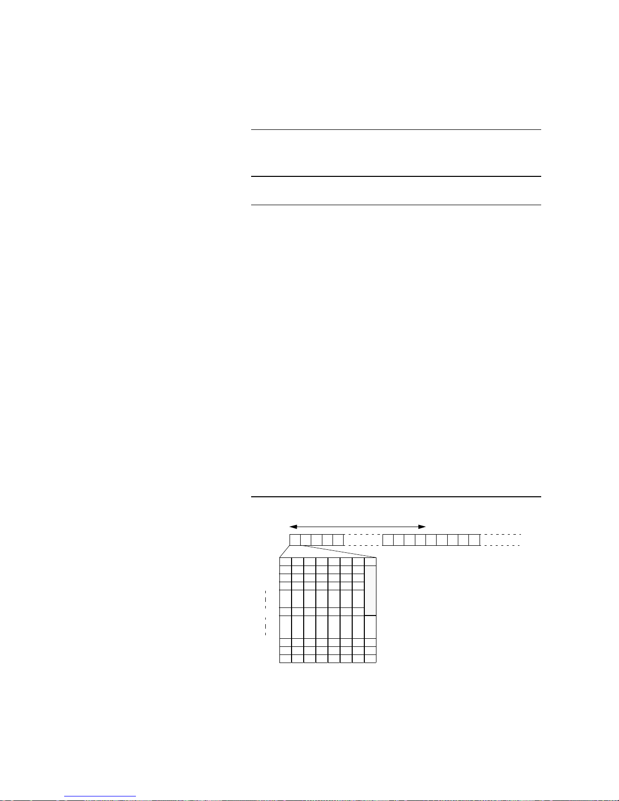
A multiplex frame of th e X.21 signal at 1920-kbit/s con sists of 30 timeslots with
8 bits each. The frame length is 125 µs (the frame frequency is 8kHz). The
structure is shown in the following figure:
FIGURE 2.5 MULTIPLEX FRAME OF THE X.21-SIGNALS (I.E. 1920-KBIT/S)
Timeslot 1 contains the J.52 inband signalling (1.6-kbit/s). The remaining
62.4-kbit/s can be filled with a single Low Speed Data channel or a single
Command channel as per G.711, G.728 or G.722.
1 2 3 4 5 1 2 3 4 527282930
Timeslot
Frame 125 µs
Bit2 Bit3 Bit4 Bit5 Bit6 Bit7 Bit8Bit1
Frame 2
Frame 3
Frame 78
Frame 79
Frame 80
Frame 1
Frame 16
J
.
5
2
LSD and CMD
LSD: Low Speed Data channel (e.g. for remote control
)
CMD: Command channel G.728, G.711 or G.722
Page 25
PAG E 2 5
SYSTEM DESCRIPTION
Network interfaces
The following network interfaces are available:
–1 × X.21, n × 64-kbit/s to 1920-kbit/s
–3 × So (ISDN)
Data interfaces
The MAGIC ISDN Audio code c has two d i f fere nt data inter faces ava ila ble for
the transmission of additional data. All interfaces are implemented as DCEs.
– HSD for High Speed Data, 64 kBit/s
– LSD for Low Speed Data between 300 and 38400Baud.
Operator interfaces
The following four operator interfaces are available for the control of the MAGIC ISDN Audio Codec:
– User I/O
– RS.232C
– RS232-AUX (on request)
– RS 485 (on request)
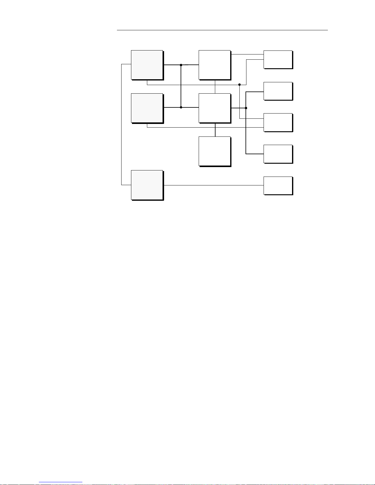
FIGURE 2.6 shows the block diagram of the int erface unit. The main e lements
are the
,2TQ\GUUQT
and the
&GOWZ &52
The J.52 DSP handles the imp limentation of the J.52 as well as control of the complete system. The Dem ux signal
processor handles the complete data multiplexing including the delay compensation for ISDN connections.
To retain the maximum flexibility, extensive use is made of
2TQITCOOCDNG .QIKE
E
QORQPGPVU
The
2..
Block
RTQXKFGU VJG KORQTVCPV ENQEMU UWEJ CU VJG
48-kHz sampling clock for
the Audio Codec and the different clocks that are necessary for X.21 operation.
The
#WFKQ &52
provides the coding according to the ITU-T-Standards G.711,
G.722 and G.728. Based on the u se of an i n dividual
#&&# %QPXGTVGT
the Command channel can operate in parallel with the ISO/MPEG Layer II/III Audio
Codec.
The
&KIKVCN +1
block generates the control signal for the
1RGTCVQT
block. in this
block, exactly as in the
.KPG &CVC
and
'ZVGPUKQP $W
s blocks, the necessary inter-
face adaptations are implimented. The only exception to be noted is the
.KPG
$NQEM
. In this block an individual pr ocessor is incorporated to handle the access
of up to six ISDN B channels. Here however , only the evaluation of th e D channel protocol is carried out. The actual user data is routed via the programmable logic to the signal processor for processing.
Page 26
PAGE 26
SYSTEM DESCRIPTION
FIGURE 2.6 BLOCK DIAGRAM OF THE INTERFACE UNIT
DSP-Bus
Operator
Line
Data
Ext. Bus
A/D-D/A
Converter
Demux-DSP
Audio-DSP
J.52-DSP
RS232C
RS485
Keyboard
Display
3 x So
1 x X.21
LSD
HSD
to Codec
Command
channel
Digital au dio
24.576 MHz
7...9 MHz
Data signals
Digital IO
Programm.
Logic
PLL
Page 27
PAG E 2 7
SYSTEM DESCRIPTION
2.5 The ‘Layer II/III Audio Codec ’
The Audio Codec plug-in unit enables the transm ission of audio signa ls at low
bit rates, as is required for ISDN, for examp le. A reduction by a factor of 1 1 for
Layer III and by a factor of 6 for Layer II is ac hieved without any loss in quality.
The encoding is in accordance with the ISO/IE C 11172-3 standar d as we ll as
the DAB ETS300401 standard.
Besides the audio channel, there is an additional data channel with a maximum data rate of 9.6-kBaud and 38.4-kBaud for DAB, which can be used to
transmit program-accompanying information, for example.
A digital, professional AES /EBU interface has been impli mented as in put and
output for the audio signal.
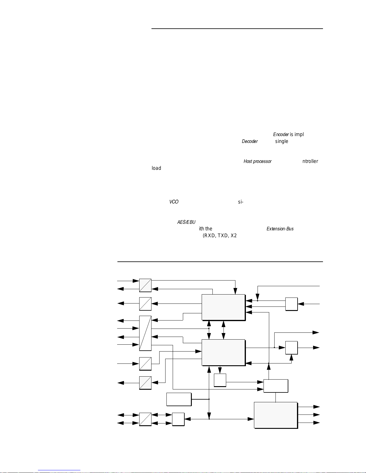
FIGURE 2.7 shows the block diagram for this unit. T he
'PEQFGT
is implimented
with four signal processors whereas the
&GEQFGT
uses a single signal processor. On the basi s of this relat ively high processing power , in general, futu re coding algoriths can be implimented.
The controlling element of this unit is the
*QUV RTQEGUUQT
. This microcontroller
loads the software for the Co dec from th e Flash -Eproms, mo nitors the Codec
and configures it. Under special control registers (De-emphasis, Mux, Level)
the analogue card is likewise controlled.
The clock can be provided in two ways: synchronous with the network clock
(only 48-kHz sampling frequency) or asynchronous with the network clock
using a
8%1
. In the second case, a qu asi-synch ron ous p roced ure is pr ovi ded
by a control algorithm in the Decoder.
The Audio data signals can be provided to the codec either from the Analogue
card or the
#'5'$7
interface.
The data exchange with the interf ace unit is over the
'ZVGPUKQP$WU
. Besides the
data and clock signals (RXD, TXD, X21_CLK, Clk_Syn) the data request signals (TXD_V, RXD_v) are still required as well as a bi-directional communications channel (XD, XC).
FIGURE 2.7 BLOCK DIAGRAM OF THE LAYER II/III AUDIO CODEC
Encoder
Layer II/III
Decoder
Layer II/III
V.24
TTL
V.11
TTL
V.11
TTL
V.11
TTL
V.24
TTL
V.11
TTL
UART
PCB-Address
VCO
Clock Mux
Host
Control
AES/
EBU
AES/
EBU
Select Sampl. Clk
RXD
Dig. Aud. Data
Deemph.
Mux
Level
Sampl. Clk (asyn.)
RTS
TXD
TXD_V
RXD_V
X21_Clk
Clk_Syn
RXD
TXD
XD
XC
Sampl. Clk (syn.)
Encoded Audio Data
Transmit Clk
AES/EBU Clk
Audio In
Audio Out
Data to D/A-Converter
Data from A/D-Converter
Hostbus
Hostbus
Hostbus
Add. Data
Add. Data
Ext. Bus
Ext. Bus
Ext. Bus
Ext. Bus
Dig. Aud. Data
Encoded Audio Data
Page 28
PAGE 28
SYSTEM DESCRIPTION
2.6 The ‘Layer II/III Audio Decoder’
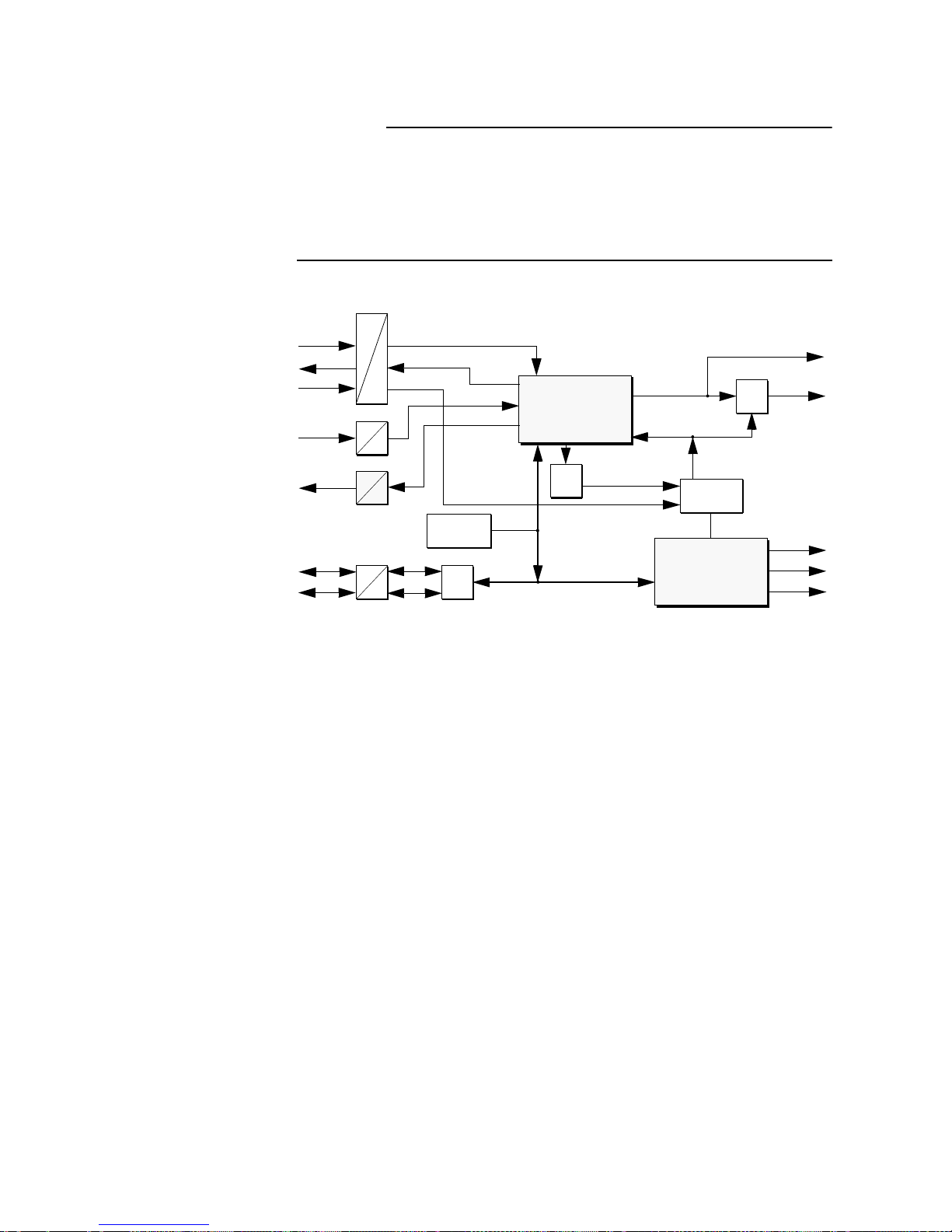
For the Decoder , it is similarly valid as shown in SECTION 2.5, except for the
restriction that the Audio signal can only be decode d. FIGURE2.8 shows the
block diagram of the Decoder. The functionality corresponds with the Codec
unit, except that it is not equipped with the Encoder.
FIGURE 2.8 BLOCK DAIGRAM OF THE LAYER II/III AUDIO DECODER
Decoder
Layer II/III
V.11
TTL
V.11
TTL
V.24
TTL
V.11
TTL
UART
PCB-Address
VCO
Clock Mux
Host
Control
AES/
EBU
Select Sampl. Clk
Dig. Aud. Data
Deemph.
Mux
Level
Sampl. Clk (asyn.)
RXD_V
X21_Clk
Clk_Syn
RXD
TXD
XD
XC
Sampl. Clk (syn.)
Transmit Clk
Audio Out
Data to D/A-Converter
Hostbus
Hostbus
Add. Data
Ext. Bus
Ext. Bus
Ext. Bus
Encoded Aud io Data
Page 29
PAG E 2 9
SYSTEM DESCRIPTION
2.7 The ‘ Audio Layer II/III Analog I’ Board
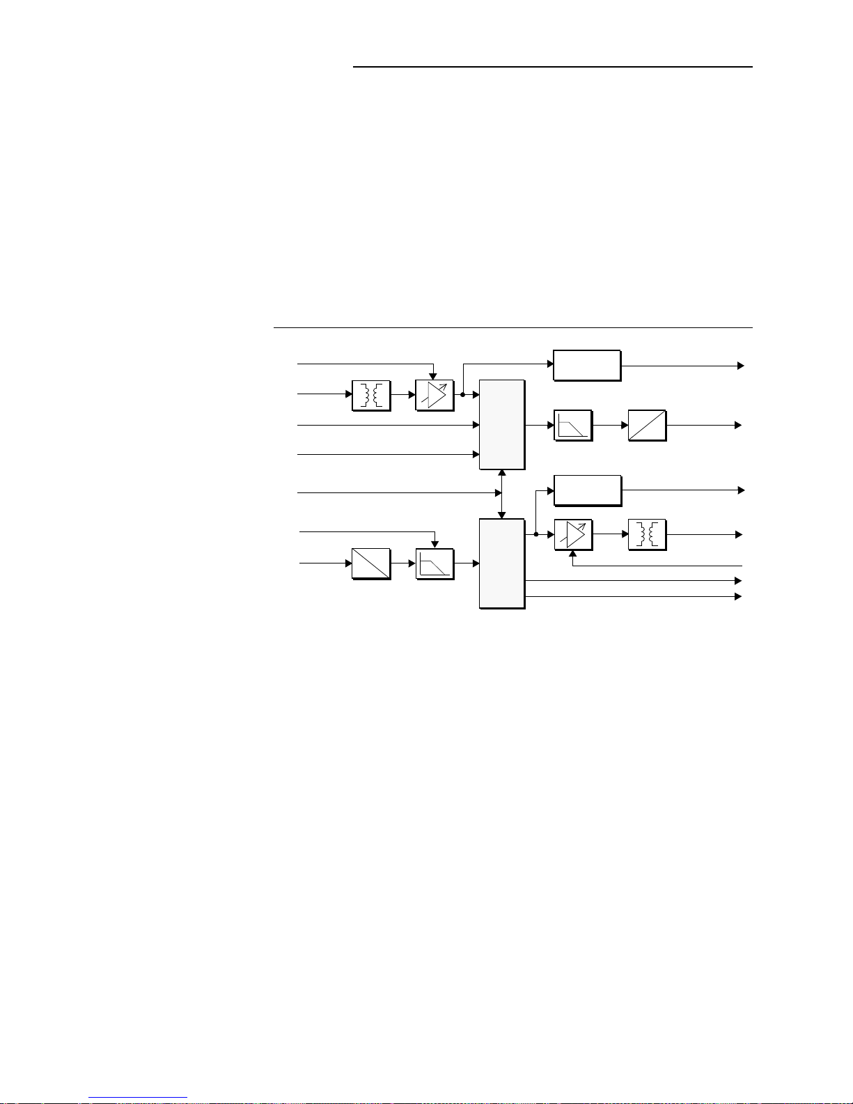
This Analogue board provides the user with earth-free and symmetrical inputs/outputs for the Audio signals. Additional possibilities are setting levels,
selecting impedance, multiplexi ng variou s Audio signals and level mon itoring.
The possibility exists via jumpers, for mid-point earthing of the Audio signals
at the main audio interface. The jumpers are marked on the printed circuit
board. As delivered, the mid-point earthing is not jumpered (see
SECTION 3.7).
FIGURE 2.9 shows the main components o f the Anal ogue boa rd. The c ontrol
of the Analogue card is from the Codec unit over the so-called Host- Bus. MUX
and DEMUX are arranged via an Audio crossb ar, through which the different
Audio signals can be switched.
FIGURE 2.9 BLOCK DIAGRAM OF AUDIO LAYER II/III ANALOG I BOARD
Level control from Codec Host
Main In
Analog
Command channel from IFE
AUX In
Mux/Demux control from Codec Host
to Codec Host
to Encoder DSP
Deemphase control from Codec Host
from Dec.
DSP
Main Out
Analog
Level control from Codec Host
to Codec Host
Command channel to IFE
AUX Out
Level cont r ol
-12 dBr
M
U
X
D
E
M
U
X
A
D
A
A
A
D
Level control
-12 dBr
Page 30
PAGE 30
SYSTEM DESCRIPTION
2.8 Example of a MAGIC system connection
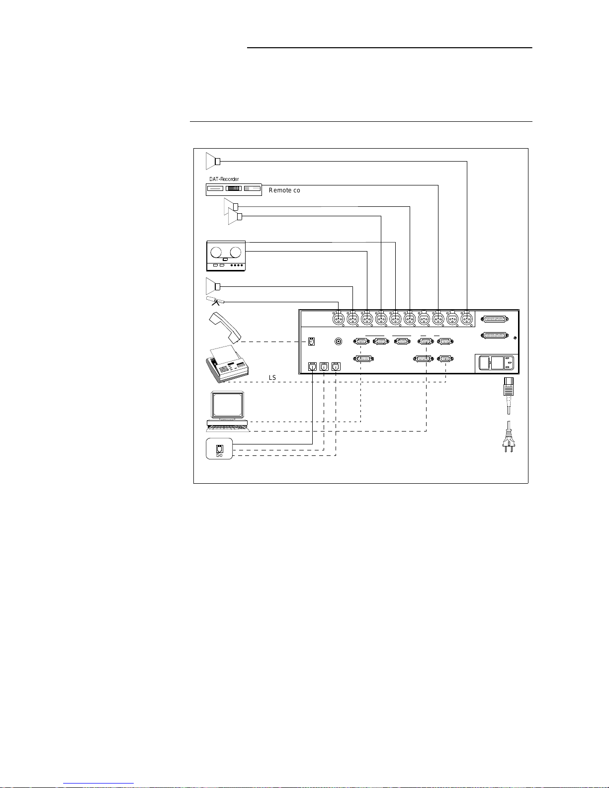
The connection of the MAGIC ISDN statio n shown here is an examp le. Not all
the units shown are always connected. Nevertheless, the varied possibilities
of which MAGIC ISDN is
simultaneously
capable of are illustrated.
FIGURE 2.10 CONNECTION OF A MAGIC ISDN UNIT WITH ANALOGUE INPUT AND OUTPUT EINGANG
AND TRANSMISSION OVER AN ISDN DIAL-UP CONNECTION
ISDN
5Q
LSD-data
Additional data for Audio signal (e.g. RDS,PAD)
Transmit sound right analogue
Command channel transmit
Command channel receive
Transmit sound left analogue
Receive sound right analogue
Receive sound left analogue
Main monitor (transmitted sound)
Receive so und (right/le ft digital)
e.g. to printer
4GEQTFGT
12:03
Remote control
Remote control
Connection of MAGIC ISDN
MAGIC control
RS232C
Line X.21 HSD LSD
Additional Data
Slot 2 Slot 3RS232-AuxRS485
Extension Bus
TTL User I/O
Handset
ISDN 1 ISDN 2 ISDN 3
Clock Out
CMD In CM D Out Left In Left Out Right OutRight In Aux In Aux OutDig In Dig Out
Telephone
Dig In Dig Out
Slot 2 Slot 3
reporting
Page 31
PAG E 3 1
3 PUTTING THE MAGIC SYSTEM INTO
OPERATION
This chapter describes how a MA GIC ISDN un it is pu t into oper ation . The following plug-in unit equipping is used as an example:
– Slot 1: Interface Unit
– Slot 2: Audiocodec Layer II/III digital
– Slot 3: Audio Layer II/III analog I (optional)
3.1 Construction of the MAGIC Audio Codec
With its dimensions of 439 mm × 133 mm (3 HE) × 395 mm (W × H × D), the
MAGIC system can either be operated as a table-top device or be inse rted into
19" or ETSI racks using mounting brackets.
The dimensions given above are valid for the table-top version with neither
mounting brackets nor feet. If the MAGIC system is to be inser ted into a rack,
it should be remembered that the bending radi us of the cables shoul d always
be greater than the minimum allowed value.
If the MAGIC system is installed in a rack, it should also be ensured that sufficient ventilation is provided. It is recommended that at least 3 cm space is
left. As a rule, the ambient temperat ure should not lie out side the range +5°C
to +40°C. These limits are of particular im port ance if the MA GIC system is inserted in a rack.
During operation, the re lative humidi ty must lie betwee n 5% and 85%. Operation of the MAGIC system outside the above-mentioned limits is not allowed
and invalidates the warranty (guarantee ).
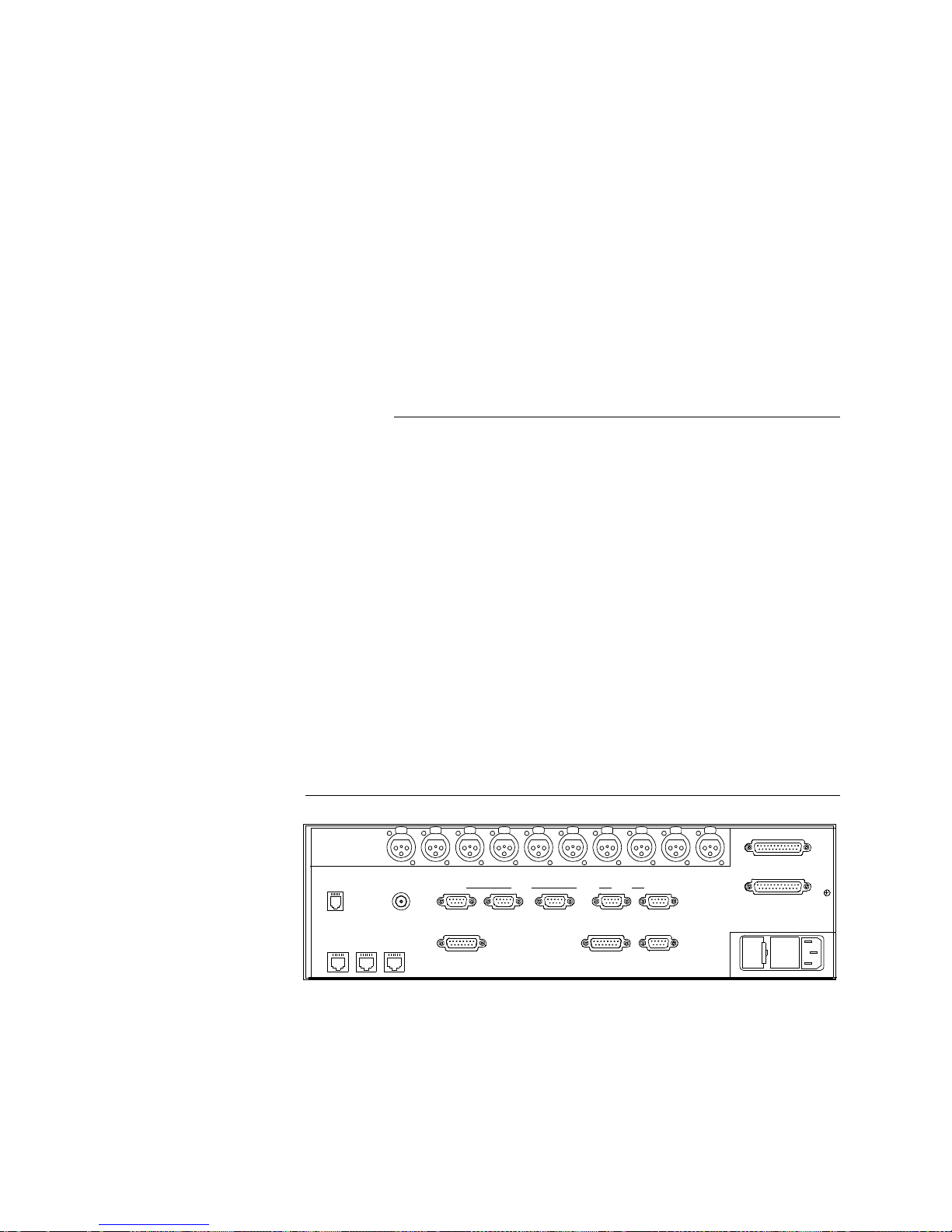
FIGURE 3.1 REAR VIEW OF THE MAGIC SYSTEM
RS232C
Line X.21 HSD LSD
Additional Data
Slot 2 Slot 3RS232-AuxRS485
Extension Bus
TTL User I/O
Handset
ISDN 1 ISDN 2 I SDN 3
Clock Out
CMD In CMD Out Left In Left Out Right OutRight In Aux In Aux OutDig In Dig Out
Dig In Dig Out
Slot 2 Slot 3
Page 32

PAGE 32
3.2 Selection of the network interface
The MAGIC ISDN Audio Cod ec offer s the operato r two types of net work inte rface. However, only one interfa ce type can b e active at a gi ven tim e. T he n etwork interface should be selected to meet the particular requirements.
The following is an over view of typical applicat ions fo r the d iffere nt network interfaces of the MAGIC system:
3.3 Connection to the data network
The selected network interface should be connected with the transmission
equipment in acco rdance with the i nterface pi n assignm ent (see Appendi x for
the pin assignments). When the So interface is selected, care is to be taken
that the connections are in numerical order. That is, in every case, ISDN No.
1 must be connected. Should a 4 B-channel connection be required correspondingly, the ISDN No. 2 interface is connected.
Network interface Application
X.21 Data interface n × 64-kbit/s, n = 1 to 30,
Block swit ching required,
3 x So ISDN interface with 6 B channels, 64-kbit/s each,
Transit time compensation between the individual channels is imnplimented.
Page 33
PAG E 3 3
3.4 Applications with MAGIC ISDN and MAGIC Systems
Some application examples with MAGIC syste ms are sho wn in the following .
In these examples, the nece ssary connectio ns correspo nding to your applications can be seen.
3.4.1 Generel Transmisssion applications in different qualities
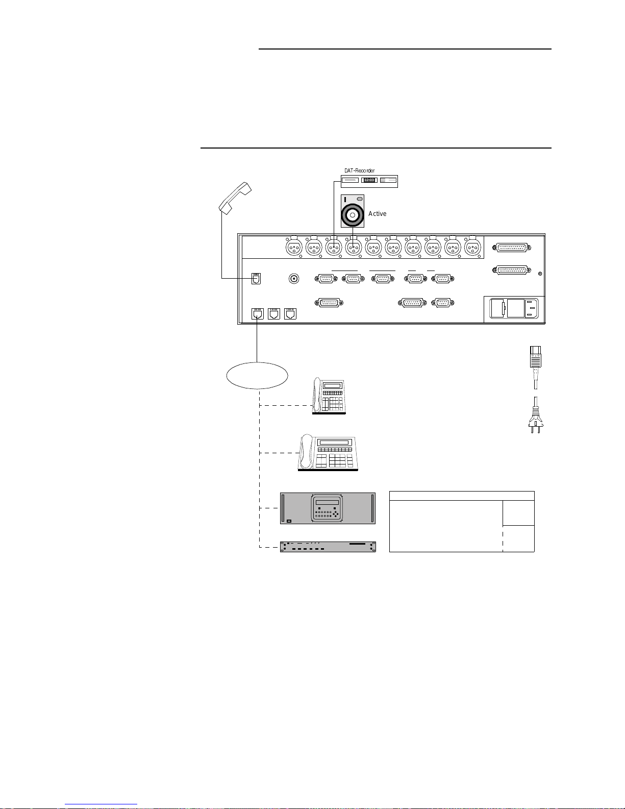
FIGURE 3.2 GENERAL TRANSMISSION APPLICATIONS WITH MAGIC ISDN
The MAGIC ISDN system is fully compatible with the AVT 15-kHz ISDN Telephone. The system automatically detects which e ncoding should be selecte d.
If you use the optionally available telepho ne handset and connect the handset
to the handset socket (any other handset can also be connected), you can
have a normal telephone conversation with the MAGIC ISDN.
Analogue/ISDN 3.1-kHz Telephone
MAGIC ISDN System
MAGIC COMPACT 7-kHz
ISDN channel B1
J.52
Audio
LSD
ISDN 1B-Channel assignment (optional data channel)
RS232C
Line X. 21 HSD LSD
Additional Data
Slot 2 Slot 3RS232-AuxRS485
Extension Bus
TTL User I/O
Handset
ISDN 1 ISDN 2 ISDN 3
Clock Out
CMD In CMD Out Left In Left Out Right OutRight In Aux In Aux OutDig In Dig Out
Dig In Dig Out
Slot 2 Slot 3
7-kHz ISDN Telephone
Telephone handset
@GEQTFGT
12:03
Active loud speaker
+5&0
Page 34
PAGE 34
3.4.2 Transmission via an X.21 channel at up to 1920-kbit/s
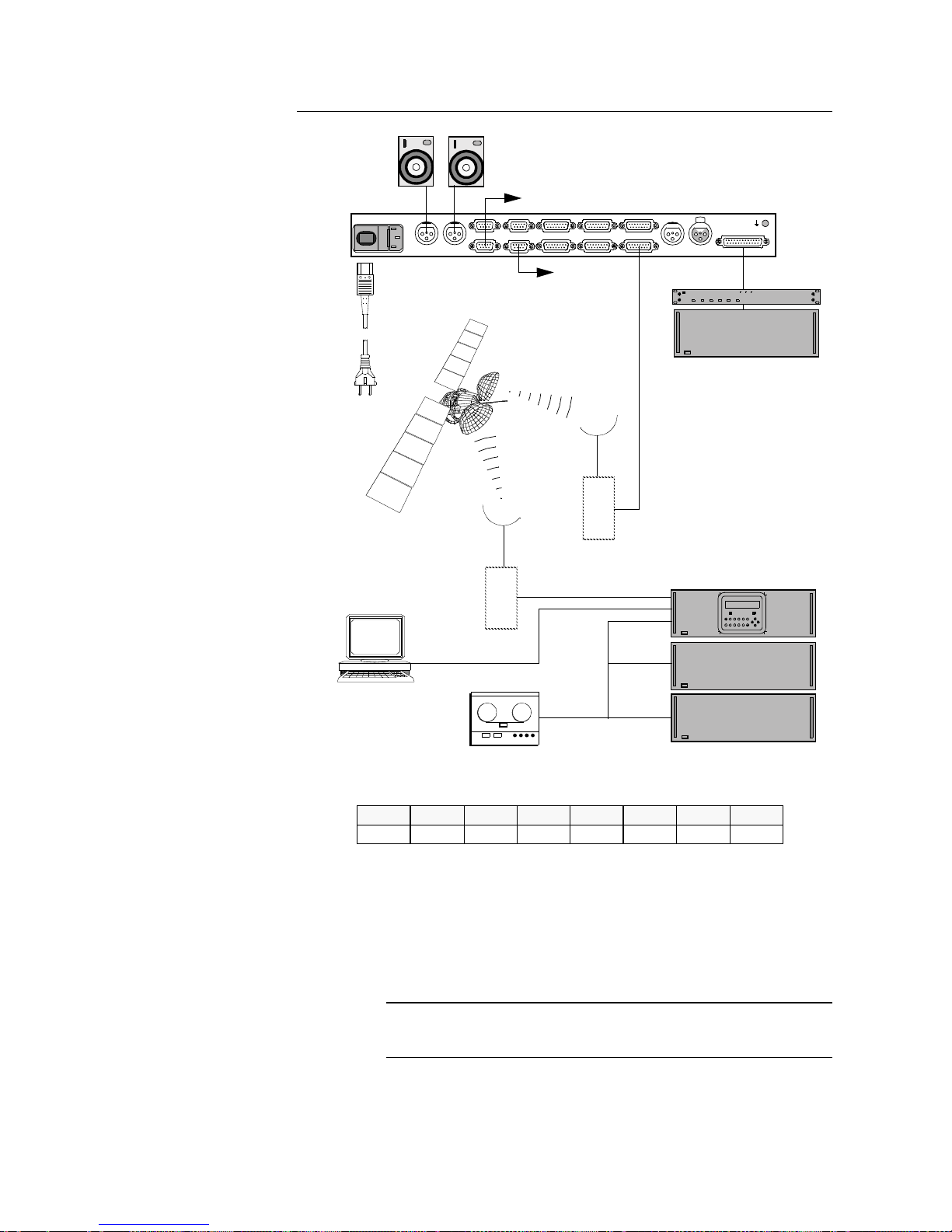
FIGURE 3.3 Transmission of up to 10 audio channels via an X.21 channel at max. 1920-kbit/s
In this operating mode, up to 10 Audio Codecs can be conn ected to the extension bus of the MAGI C system. The transmission is, for example, via a satellite
channel at a data rate of 1920-kbit/s. The source is a MAGIC ISDN system
with additional extension units.
Remark
The 1920-kbit/s datar ate is a softwar e option w hich can ce o btained under order number 333475. Without this software option, the maximum transmission data rate is up to 384 kbit/s.
POWER 115/230V
0 I
LEFT OUTPUT RIGHT
OUTPUT CMD INPUT
EXTENSION BUS
USER I/O X.21/SLAVE 4 X.21/SLAVE 2 X.21/MAIN
X.21/SLAVE 1X.21/SLAVE 3X.21/SLAVE 5
LSD
RS232C
ADD.DATA
MAGIC System control
MAGIC Extension
COMPACT D
Extensio n Bus
Satellite
downlink
Satellite
uplink
Loudspeaker, modulator
X.21 Line t o 1920-kbit /s
(max. 10 Audio signals)
max. 10 St er eo Audio sou r ces
TTL remote commands
RDS Data
X.21-Line to 1920-kbit/s
(max. 10 Audi o signals)
MAGIC COMPACT D
PHILIPS
TS 1 TS 2 TS 3 TS 4 TS 30TS 29..........
J.52 Audio 1 Audio 1 Audio 2 Audio 10Audi o 10
..........
Possible channel allocation:
MAGIC ISDN
Page 35
PAG E 3 5
3.4.3 Transmission of an audio signal with the signalling switched off
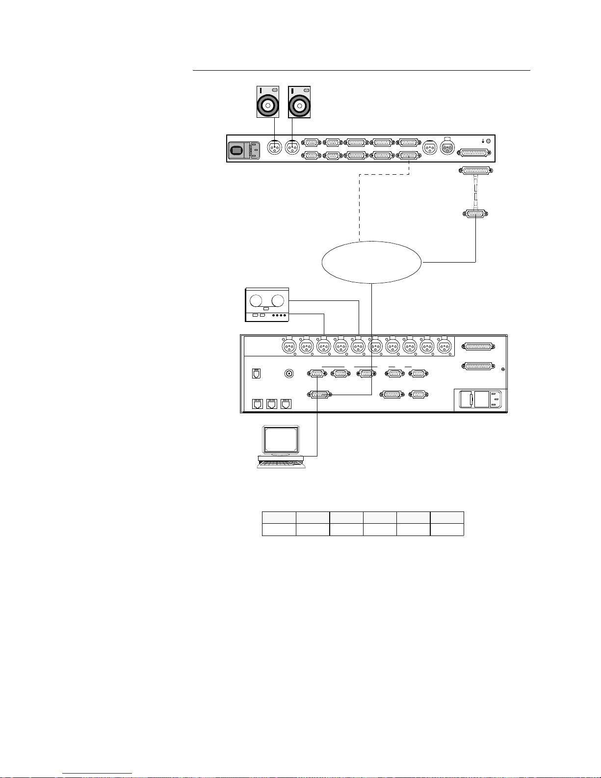
FIGURE 3.4 Transmission of an audio signal without J.52 signalling
In this operating mode, 1 audio programme can be transmitted via a leased
line at a data rate of 64 to 384-kbit/s (for Layer III, up to 256-kbit/s).
POWER 115/230V
0 I
LEFT OUTPUT RIGHT
OUTPUT CMD INPUT
EXTENSION BUS
USER I/O X.21/SLAVE 4 X.21/SLAVE 2 X .21/MAIN
X.21/SLAVE 1X. 21/SLAVE 3X.21/SLAVE 5
LSD
RS232C
ADD.DATA
MAGIC Syste m co nt r ol
Loudspeaker, modulator
Transmission of an Audio programme
(for MAGIC COMPACT D)
MAGIC ISDN
Adapter cable X.21 <--> Ext. Bus
nx64-kbit/s
leased line
(n=1...6)
X.21 cable
(for MAGIC COMPACT DDC, DD)
X.21 cable
left
right
Audio
Channel assignment for leased line operation and Layer II encoding:
Audio Audio Audio Audio Audio
RS232C
Line X.21 HSD LSD
Additional Data
Slot 2 Slot 3RS232-AuxRS485
Extension Bus
TTL User I/O
Handset
ISDN 1 ISDN 2 ISDN 3
Clock Out
CMD In CMD Out Left In Left Out Right OutRight In Aux In Aux OutDig In Dig Out
Dig In Dig Out
Slot 2 Slot 3
TS 1 TS 2 TS 3 TS 4 TS 5 TS 6
Page 36
PAGE 36
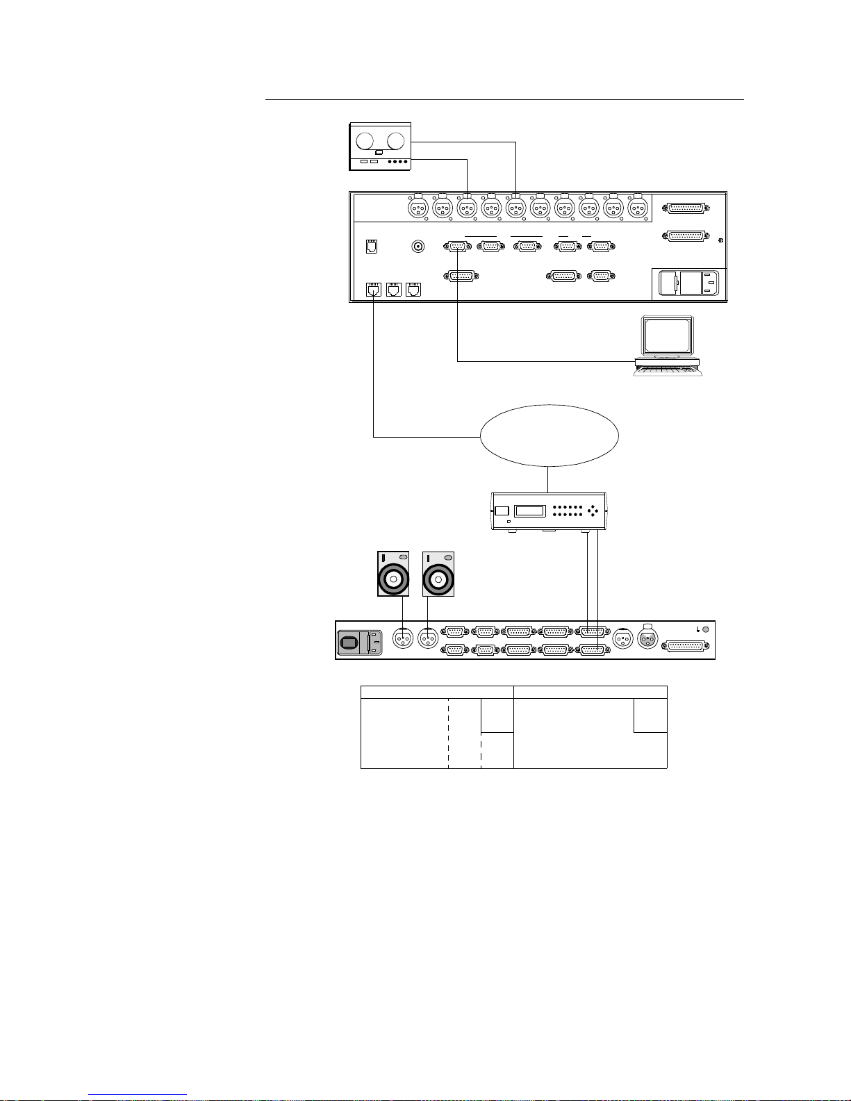
3.4.4 Audio transmission via ISDN
FIGURE 3.5 A
UDIO TRANSMISSION VIA
ISDN
WITH
2 B
CHANNELS
In this application, the uni-directional transmission of a high-quality audio signal via an ISDN connection (128 kbit/s) is shown. To set up a bi-directional
Audio connection, the MAGIC ISDN System (or e.g. a MusicTaxi) equipment
must have the same settings at both ends of the transmission path. MAGIC
systems in ISDN operation can be used to transmit Audio data at up to 384kbit/s. For all six B -channels, a transit tim e delay com pensation i s carr ied out.
Then a "Capability Exchange" takes place in which the terminals exchan ge information on their encoding and decoding capabilities. At the end of this procedure, the audio signals are transmitted in the best possible mode (unless
this is limited by the use of further data services). If MusicTAXI signalling has
been selected, a 2B connection is set up. Several features such as an additional "Low Speed Data" channel or the complete remote control of systems
are therefore not possible in this mode.
RS232C
Line X.21 HSD LSD
Additional Data
Slot 2 Slot 3RS232-AuxRS485
Extension Bus
TTL User I/O
Handset
ISDN 1 ISDN 2 ISDN 3
Clock Out
CMD In CMD Out Left In Left Out Right OutRight In Aux In Aux OutDig In Dig Out
Dig In Dig Out
Slot 2 Slot 3
POWER 115/230V
0 I
LEFT OUTPUT RIGHT
OUTPUT CMD INPUT
EXTENSION BUS
USER I/O X.21/SLAVE 4 X.21/SLAVE 2 X.21/MAIN
X.21/SLAVE 1X. 21/SLAVE 3X.21/SLAVE 5
LSD
RS232C
ADD.DATA
Loudspea ker, modulator
Transmission of an Audio programme
MAGIC ISDN
left
right
#inclu
TA MULTI
ISDN channel B1 ISDN channel B2
J.52
J.52
Audio
Audio
LSD
ISDN 2B channel assignment (optional data channel and command channel):
CMD
MAGIC Sy stem contro l
+5&0
Page 37

PAG E 3 7
3.5 Connection to the mains voltage
The MAGIC system can be oper ated with an AC voltage (mains) between 90
and 253 V without the need for switching. The mains frequency can vary between 45 Hz and 65 Hz. The power consumption is a maximum of approx.
70 W. The housing must be earthed (grounded) in accordance with local regulations. This earthing is usually realised via the protective conductor
(green/yellow) of the mains cable. If the mains cable does not have a protective conductor, however, the device must be earthed via the earthing screw
(see FIGURE 3.1).
NOTE
Use the mains cable provided! Do not use an extensi on cable
without a prote ctive conductor! If in doubt, use ad ditional GND!
3.6 Opening the Device
NOTE
The device must be discon nected from mains b efor e it is opened!
Although a large part of the system configuration can be carried out fro m the
outside using software, it is sometimes necessary to open the device. To do
this, remove the four sc rews on the fr ont p anel . The p anel ca n now b e pull ed
out by the handles. The keypad/display unit can also be removed. The individual plug-in units are inserted horizontally and can easily be removed or inserted using the lever provided.
NOTE
Dangerously high voltages can still be present on the power
supply even several minutes after it has been disconnected
from the mains. Do not, therefore, touch any component or
soldering point on the power supply!
The plug-in units of the System can be seen in the table in SECTION 2.2.
To re-assemble the unit, carry out the above steps in reverse order.
Page 38
PAGE 38
3.7 Setting the centre-tap earth for the analogue audio inputs
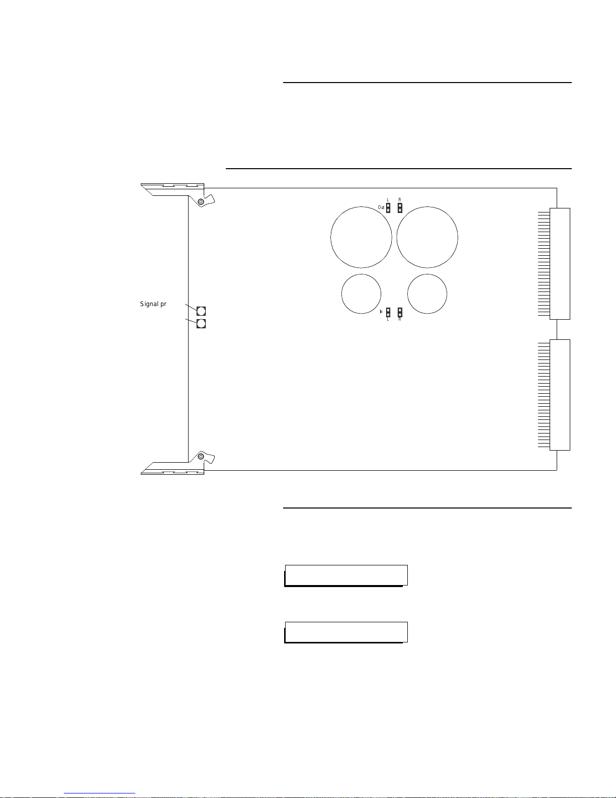
The plug-in unit Audio Codec Layer II/III analogue I has four jumpers with
which the centre-tap earth can be set for each channel. FIGURE 3.6 shows
the position of the jumpers. In the factory setting, cent re-tap earthing is not selected.
FIGURE 3.6 JUMPERS ON THE PLUG-IN UNIT AUDIOCODEC LAYER II/III ANALOGUE I
3.8 Switching on the system
After all required interfa ces have been connect ed, the system can be switched
on. The following message appears on the front panel display:
After a few seconds, the main menu appears:
The system is now ready for oper ation a nd the f irst conn ection ca n be set up.
1WV
.
4
+P
.
4
Signal present
Level monitoring
activated
**** M A G I C 6 B ****
BOOTING SYSTEM...
*CALL RD DIS CFG SYS MEM
SYSTEM BOOTED
Page 39
PAG E 3 9
OPERATION WITH THE OPERATOR PANEL
4 OPERATION WITH THE OPERATOR PANEL
The menus that can b e called up from t he operat or (front) pa nel are described
in the following sections.
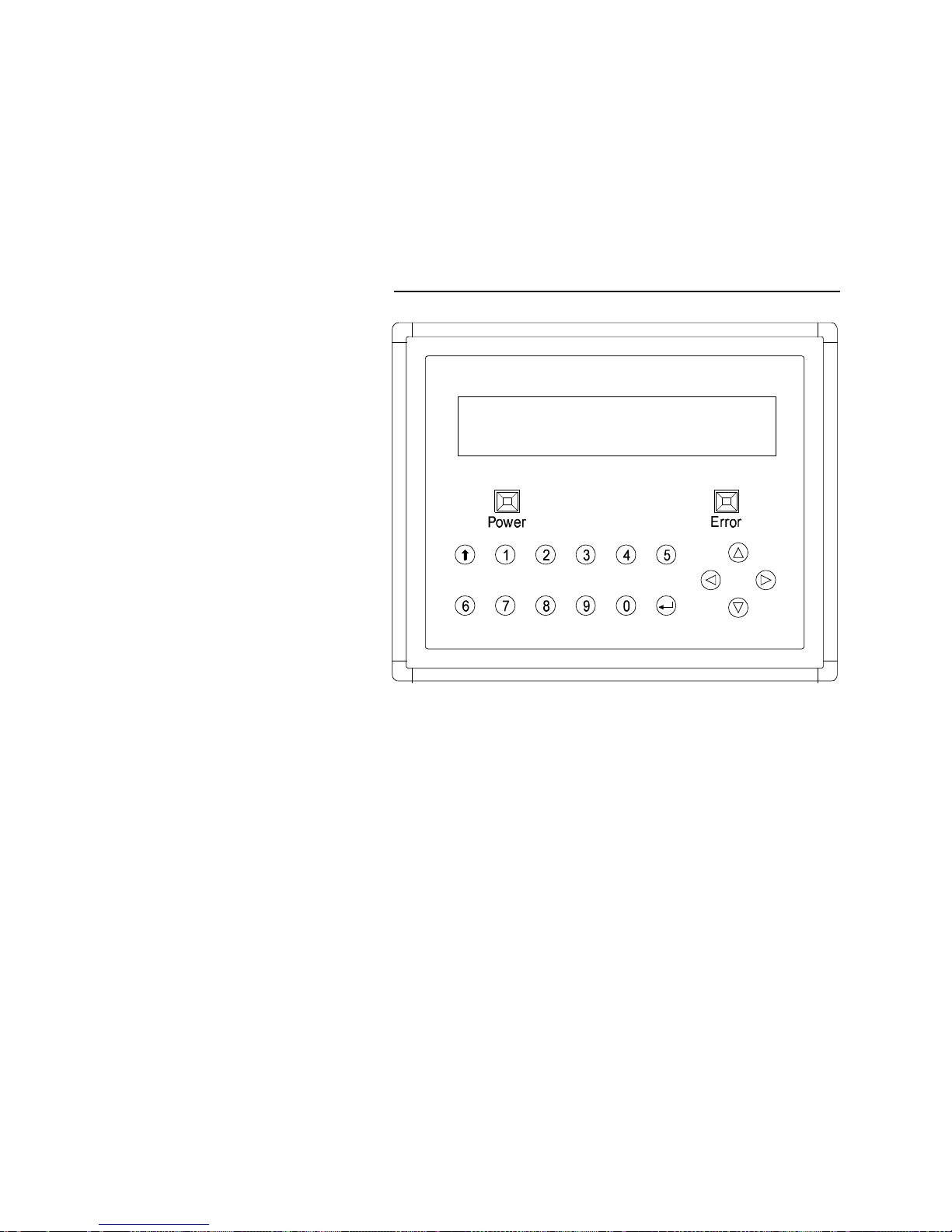
FIGURE 4.1 OPERATOR PANEL OF THE MAGIC AUDIO CODEC
The MAGIC operator panel consists of a two-line display with 24 characters
per line, a keypad with the digits 0 to 9, an Enter key, a cursor block and an
Escape key.
In addition, the operator panel has two LEDs The „Power“ LED lights when th e
unit is in operation, and the „Error“ LED lights up if there is a system alarm.
Page 40

PAGE 40
OPERATION WITH THE OPERATOR PANEL
4.1 Menu tree
The different men us di splaye d in the MAGIC oper ator pane l are o rga nised in
a tree structure. The root of the tree structure is the main menu, which is displayed when the system is switched on:
Main menu
The first line of a displayed menu always contains the functions or subm enus
that can be activated. The second line contains additional information on the
currently selected men u item. T he cu rsor block keys ar e used to move to the
required menu item in the menu tree.
By pressing the or
key,
the neighbouring menu item (to the right or left)
is selected (horizontal movements in the menu tree). The asterisk
(∗)
indicates
the currently selected menu item.
With the key, th e selected submenu can be called up. The key calls up
the previous menu (vertical movement in the menu tree).
The Return (Enter) key confirms a selection (e.g. activate s a selected network interface) or a menu item that requires the entry of data (e.g. a calling
number). Such menu item s are always i ndica ted with a “?” in the second line
of the display.
The Escape key exits a data entry menu or calls up the main menu from
any other location in the menu tree .
Every pressing of a key is acknowledged acoustically.
The menu structure makes it possible to change individual parameters directl y
without having to repeat all settings.
The main menu consists o f five submenus. These are described brief ly on the
following page. Th e com plete me nu tree is shown diag ram mat ical ly i n Ann ex
4.1, Page 46 to Annex 4.5, Page 50. This list is to be used as a reference if
settings are to be made. The list shows all menu levels down to the l ast level.
The individual possible selections in the last level are not shown in the list.
Remark
SECTION 4.5 contains an example of how letters and other
characters can be entered via the operator panel..
*CALL RD DIS CFG SYS MEM
Call menu
Page 41

PAG E 4 1
OPERATION WITH THE OPERATOR PANEL
4.2 The main menu
The main menu consists of five m enu items that are exp lained in the followi ng.
CALL
:
From this menu item:
– NAME can be selected if 1..6∗X.21 has been set as the line interface,
– A connection can be set up (CONN) for all other line interface settings,
– A calling number can be stored (SET),
– The automatic call answering can be switched on or off.
RD
:(
ReDial
)
selecting this menu item redials the last connection dialled.
DISC
:(
DISConnect
)
selecting this menu item disconnects all existing connections.
CFG
:(
ConFiGuration
)
With this parameter:
– Layer III/ISO/MPEG audio codecs (AUDIO) can be configured
– The command channel (BACKCH) can be configured
– The High-Speed and Low-Speed data channels (DATA) can be set
SYS
:(
SYStem settings
)
All system parameters can be set and displayed.
– Display of the current alarms (ALARM)
– Setting of all interfaces (IFACE), including the audio interfaces
– Switching of test loops (LOOP)
– Setting and polling of unit parameters (ETC), such as software version
MEM
:(
MEMory settings
)
This menu item is used to mana ge the 10 memo ry location s av ailabl e for the
storing of configurations. The following functions are provided:
– Loading a configuration (LOAD).
– Saving a configuration (SAVE).
– Initialise unit (INIT).
– Select unit default setting (DF).
Most of these menu items are self-explanatory and easy to use. The procedure for storing calling numbers and unit configurations is described in
SECTION 4.5.
Page 42

PAGE 42
OPERATION WITH THE OPERATOR PANEL
4.3 Submenus
Some specific submenu functio ns are de scribed in more deta il here. In gen eral, the description o f the PC user in terface comman ds (see Software Descr iption) can be used, since the designations are almost identical in most cases.
NAME
:
In the ISDN dialling mo de, the nam e of a pr eviously sto red part ner can be selected.
MAN
:
Under manual call, the number of a partner which has not been previously
stored, can be entered and called directly. Any telephone or 64-kbit/s or 128kbit/s data connection is possible.
CONN
:
To activate connections that are not set up via ISDN such as X.21 connections, CONN must be pressed at both ends.
ANSW
:
For a dialled call to be answered automatically, ANSW must be switched on.
ALARM
:
Alarms which are present are displayed.
LOOP
:
– LOCAL The signal is looped back at the network interface. The data
stream is fed into the tr ansmission path an d is also retu rned to
the Interface Unit.
– REMOTE The incoming data stream is retu rned to the t ransmission path.
The local MAGIC station receives th e incoming signal,which is
returned to the remote station. This test involves the trans mission route.
– OFF No loop is switched. This setting should always be selected
before the panel is exited.
Remark
The loop is always of the active network interface.
Please ensure that no loop is set when the panel is exited.
DISP
:
The value in brackets shows the currently set display contrast.
CTRL
:
The settings for the transmission parameters (MODE, RATE, BITS, PARITY)
of the RS232C (V24) and the RS485 (RS) interfaces can be made with this
function. For the RS485 interface, this is the only setting possibility.
Attention
STR (string format) should never be selected under MODE,
since the control PC will not function in this setting.
!
Page 43
PAG E 4 3
OPERATION WITH THE OPERATOR PANEL
4.4 Entering the commands
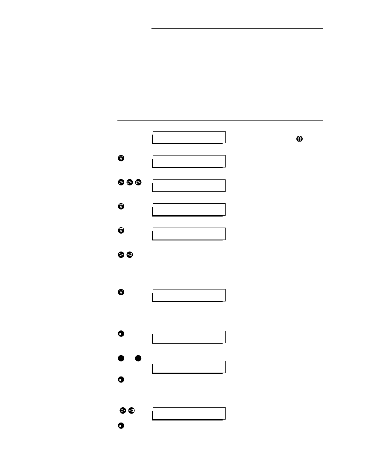
To set a function, search for the corresponding menu in the menu tree (displayed diagrammat ically from page 4-47 to page 4 .51) and ca ll up the function
using the cursor keys provided on the keypad. Make the setting and confirm
with Return. The following two sections contain examples of operator panel
entry.
4.5 Programming example: Storing calling numbers
Keys Display Remarks
Main menu This is the starting point of the menu tree.
To obtain this menu from any other
menu, press the escape key .
Activate the
CALL
submenu by pressing
the „down“ curosr key.
With the „right“ cursor key, select the
SET
menu item.
Press the „down“ cursor ke y to call up the
SET
submenu.
Call up the
NRS
submenu by pressing
the „down“ cursor key
)
Mark the required servic e with the „right“/
„left“ cursor keys:
DA TA
: Call with data service indicator
(SI)(Default 1..6B)
TEL:
Call withTelephone SI (1B)
Press the „down“ cursor key to select the
DA T A
submenu.
Entering the Country Code and the Local Area Code
Call up the
AREA
submenu with the
Enter key.
bis
Enter the country code and/or the local
area code with the keys 0 to 9.
Confirm with the Enter key. The
NRS
submenu is then a utomatically calle d up.
Entering the calling number
( )
Use the „right“ / „left“ cursor keys to select the required number N1 to N6. Call
up the submenu with Enter.
*CALL RD DIS CFG SYS MEM
Call menu
*NAME MAN CONN SET ANSW
Call by name
NAME MAN CONN *SET ANSW
Set call-by-name memory
*NRS MODE SAVE ERASE
Set call numbers
*DATA TEL
Set data call
*AREA N1 N2 N3 N4 N5 N6
Area code
Enter area code:
0911
0 9
*AREA N1 N2 N3 N4 N5 N6
Area code
Enter phone number:
9952705
Page 44
PAGE 44
OPERATION WITH THE OPERATOR PANEL
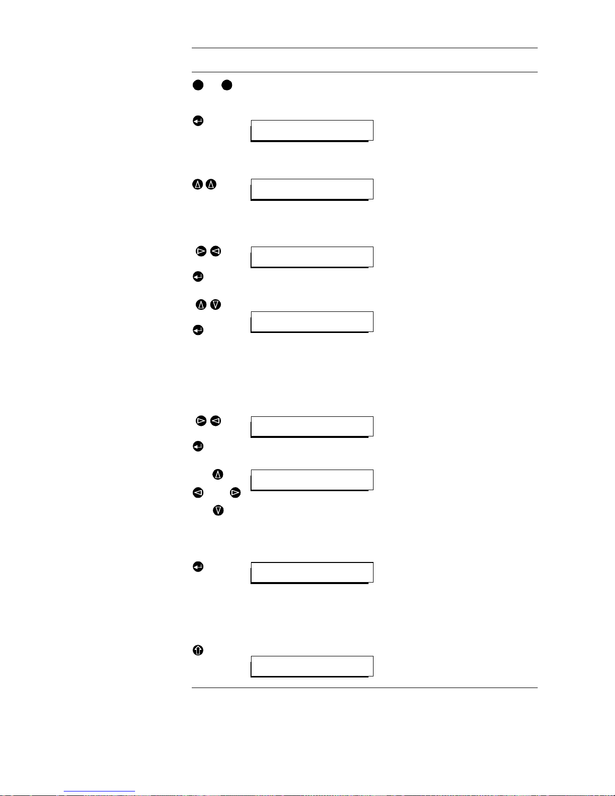
The calling numbers are now stored under the desired names.
bis
Enter the callin g number (wi thout country
code and local area code) and confirm
with Enter.
The
NRS
submenu is then automat ically
called up.
T o enter further c alling numbe rs, select a
number from N1 to N6 and proceed as
described above.
Return to the
SET
submenu with the „up“
cursor key.
Selecting the unit configuration
( )
With the „right“ / „left“ cursor keys, select
the
MODE
menu and then press E nter to
call up the
MODE
submenu.
( )
MODE submenu
With the „up“ and „down“ cursor keys,
select the required configuration and
confirm with Enter. The
SET
submenu is
then called up automatically.
This configuration must then be saved.
Saving
( )
Select
SAVE
with the „right“ / „left“ cursor
keys and call up the
SA VE
submenu with
Enter.
Enter a name for the dialled
connection. The letters and characters
are selected by repeatedly pressing the
„up“ / „down“ cursor keys. If the name
consists of several characters, use the
„left“ / „right“ cursor keys to pla ce the cu rsor accordingly .
Confirm the configuration name with
Enter. A message appears to indicate
that the data has b een stor ed. Pr ess any
key to return to the
SET
submenu.
Main men u
Pressing the Escape key calls up the
main menu, starting point for the other
settings.
Keys Display Remarks
0 9
AREA *N1 N2 N3 N4 N5 N6
Number 1
*NRS MODE SAVE ERASE
Set call numbers
NRS *MODE SAVE ERASE
Set call mode
Select configuration:
MUSICTAXI
NRS MODE *SAVE ERASE
Save call-by-name data?
Enter call name:
TESTLOOP
Call data stored!
Press any key!
*CALL RD DIS CFG SYS MEM
Call menu
Page 45
PAG E 4 5
OPERATION WITH THE OPERATOR PANEL
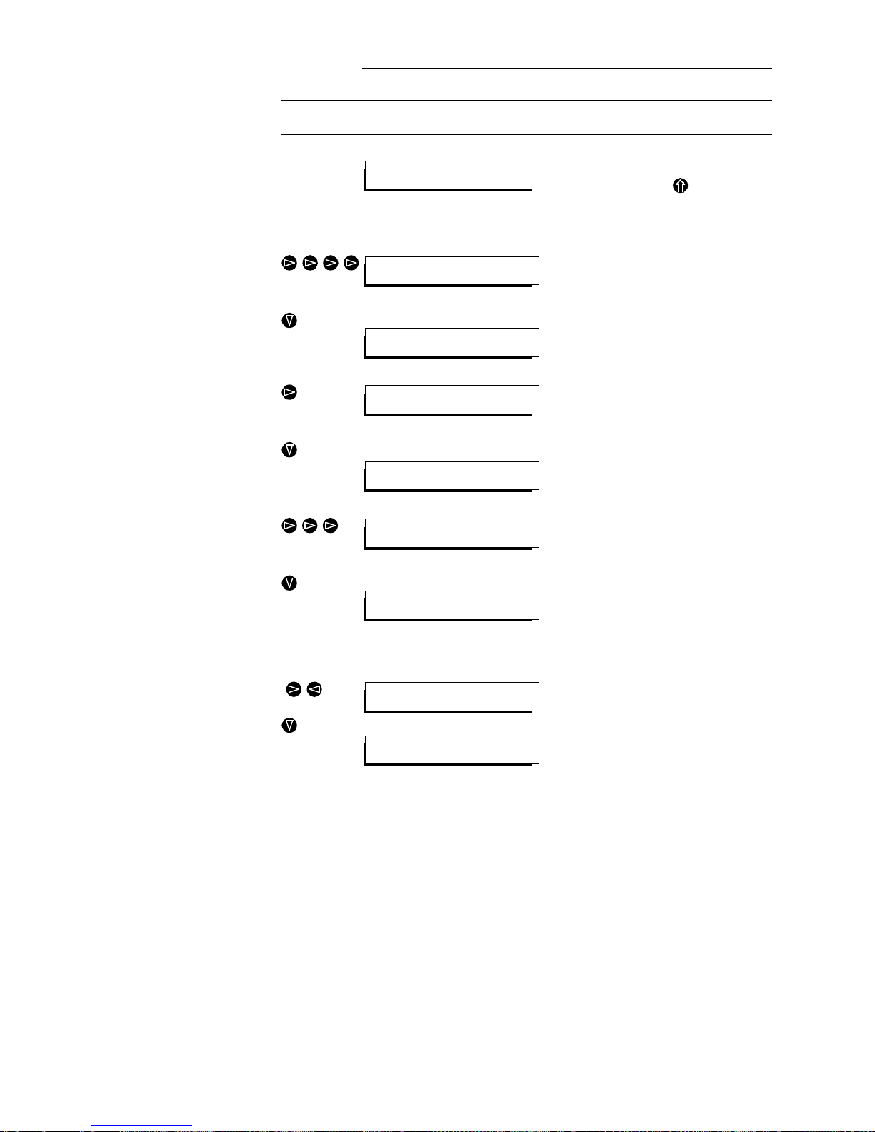
4.6 Programming example: setting the RS232C for control via a PC
Key Display Remarks
Main menu This is the starting point of the menu tree.
T o obtain this menu fro m any other menu
press the Escape key .
Calling up the CTRL submenu
With the “right” cursor key, select the
SYS
menu.
SYS submenu Activate the
SYS
submenu by pressing
the “down” cursor key.
With the “right” cursor key, select the
IFACE
menu.
IFACE submenu Press the “d own” cursor key to call up the
IFACE
submenu.
With the „right“ cursor key, select the
CTRL
menu.
CTRL submenu Press the “down” cursor key to call up the
CTRL
submenu.
Choosing the interface to be set
( )
With the „right“ / „left“ cursor keys, select
the required interface (e.g.
V24
).
Meanings:
V24 RS232C serial interface
RS RS485 bus interface
TTL User I/O interface
With the „down“ cursor key , select the appropriate submenu.
*CALL RD DIS CFG SYS MEM
Call menu
CALL RD DIS CFG *SYS MEM
System setups/tests
*ALRM IFACE LOOP ETC
Show alarms
ALRM *IFACE LOOP ETC
Interface setups
*LINE AUDIO DATA CTRL
Line interface select
LINE AUDIO DATA *CTRL
Ctrl interface setup
*V.24 RS TTL
Setup V.24-Ctrl
*V.24 AUX RS TTL
Setup V.24-Ctrl
*MODE RATE BITS PARITY
Set packet/string mode
Page 46
PAGE 46
OPERATION WITH THE OPERATOR PANEL
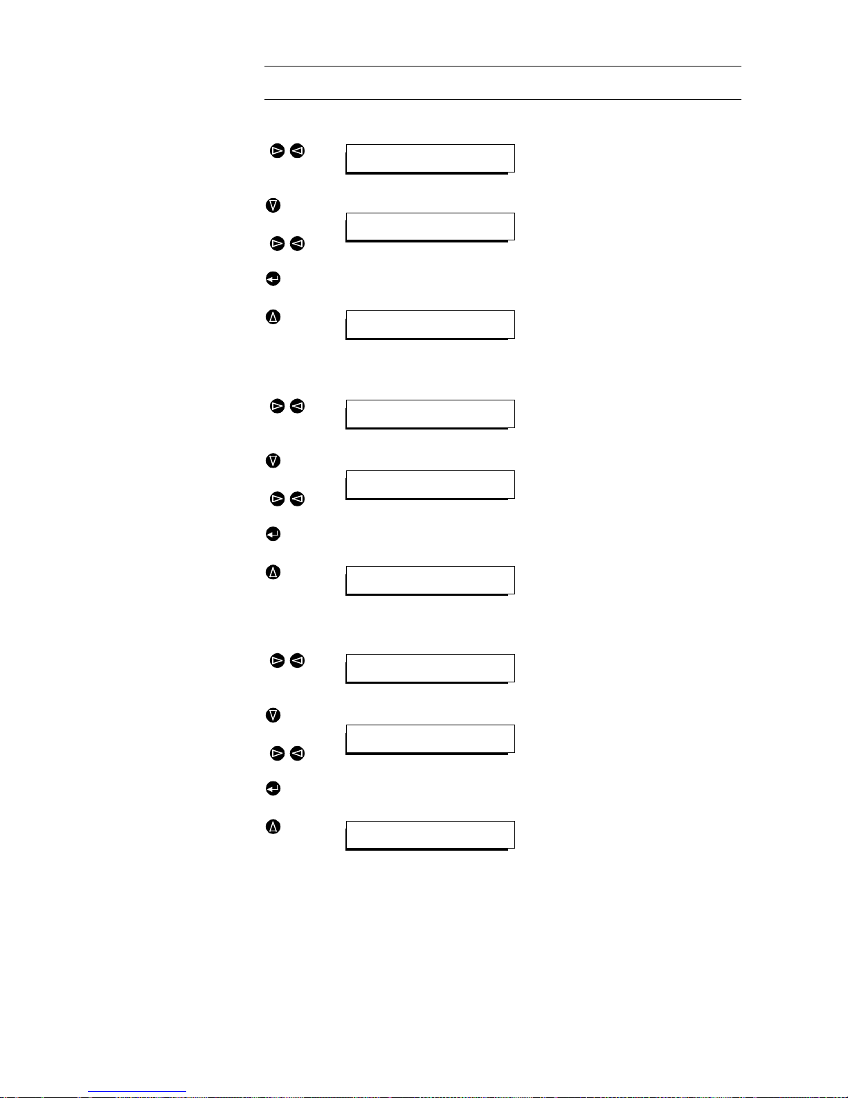
Setting the Mode (string / packet)
( )
With the „right“ / „left“ cursor keys, select
the MODE menu.
( )
MODE submenu Press the “down” cur sor key to call up t he
MODE submenu. The star stands at the
presently selected mode.
With the „right“ and „ left“ cursor key s, select
PKT
(packet format) and conf irm with
Enter.
Press the “up” cursor key to return to the
selected interface.
Setting the data rate
( )
With the „right“ / „left“ cursor keys, select
the RAT E menu.
( )
RATE submenu
Press the “down” cur sor key to call up t he
RATE submenu. The star stands at the
presently selected data rate.
With the „right“ and „ left“ cursor key s, select the
192
data rate (=19200 Baud) and
confirm with Enter.
Press the “up” cursor key to return to the
selected interface submenu.
Setting the data format
( )
With the „right“ / „left“ cursor keys, select
the BITS menu.
( )
BITS submenu
Press the “down” cur sor key to call up t he
BITS submenu. The star stands at the
presently selected format.
With the „right“ / „left“ cursor keys, select
the 8 bit format and confirm with Enter.
Press the “up” cursor key to return to the
selected interface.
Key Display Remarks
*MODE RATE BITS PARITY
Set packet/string mode
*STR PKT
String format?
*MODE RATE BITS PARITY
Set packet/string mode
MODE *RATE BITS PARITY
Select rate
*3 12 24 48 96 192 384
300 baud?
MODE *RATE BITS PARITY
Select rate
MODE RATE *BITS PARITY
Set 7/8 bits
*7 8
7 bit format?
MODE RATE *BITS PARITY
Set 7/8 bits
Page 47
PAG E 4 7
OPERATION WITH THE OPERATOR PANEL
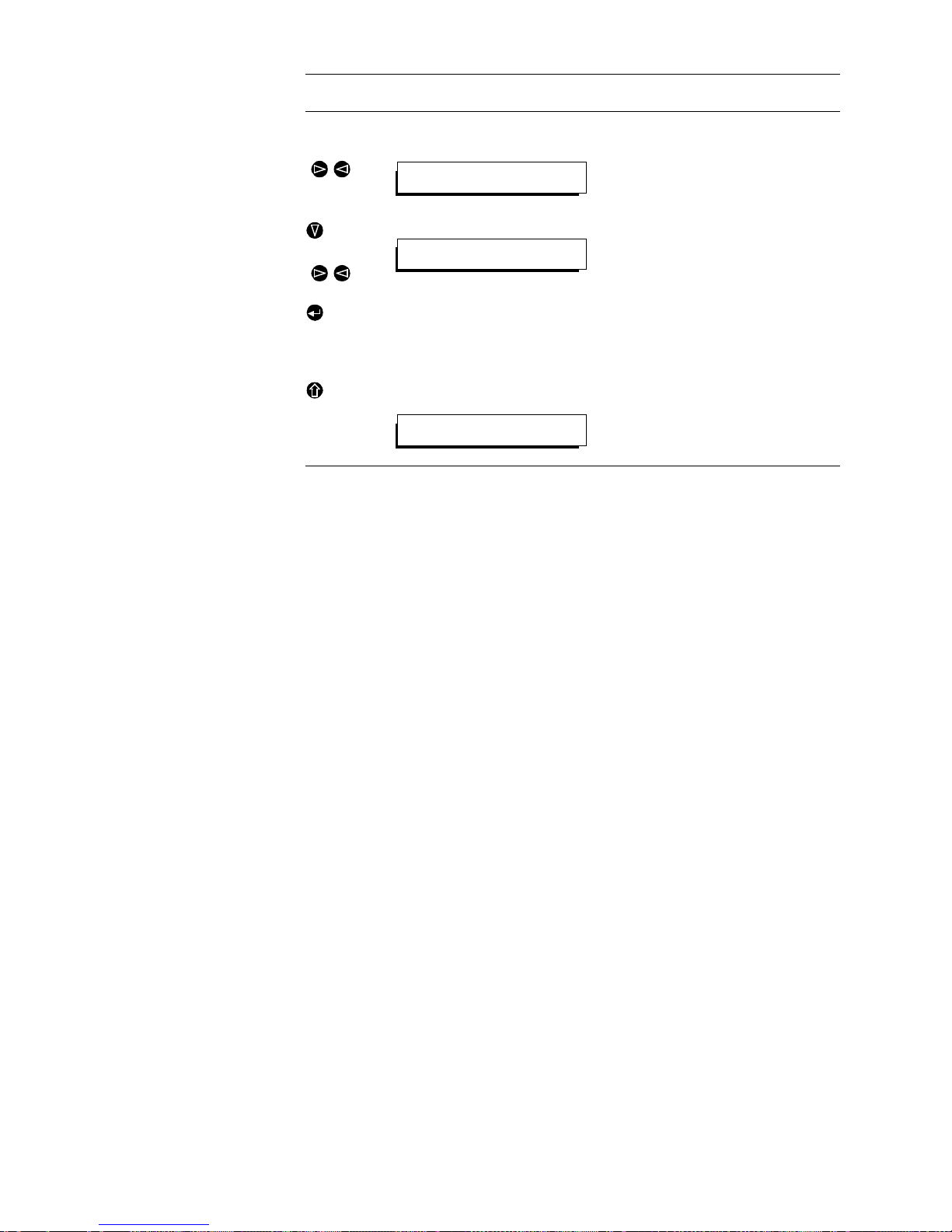
The configuration of the RS232C user interface is now completed.
Setting the parity
(RS232C only)
( )
With the „right“ / „left“ cursor keys, select
the
PARITY
menu.
( )
PARITY submenu Press the “down” cursor key to call up the
PARITY
submenu. The star sta nds at the
presently selected parity.
With the „right“ / „left“ cursor keys, select
the
NONE
parity and confirm with Enter.
Main
menu
Pressing the Escape key calls up the
main menu, starting point for the other
settings.
Key Display Remarks
MODE RATE BITS *PARITY
Set parity
*NONE EVEN ODD
No parity?
*CALL RD DIS CFG SYS MEM
Call menu
Page 48

PAGE 48
OPERATION WITH THE OPERATOR PANEL
Page 49

PAG E 4 9
TECHNICAL DATA
ANNEX1 TECHNICAL DATA
A1.1 Interface Unit with variable network access
Signaling /Synchronisation
ITU-T Recommendations J.52 (H.221/H.242)
ITU-T Recommendation H.331 for unidirectional links
MusicTAXI mode (DIALOG4, 2-B channels)
CCS Mode ISO/MPEG Layer 2 (2-B-channels)
Signalling can be switched off with/without Bit-Inversion
Coding Algorithms
ITU-T-Recommendations G.722, G.711 or
GSM (3.1-kHz coded at 16-kbit/s )
G.728 (3.1-kHz at 16-kbit/s)
Network interfaces
1 × X.21 Data rate n × 64-kbit/s to 1920-kbit/s
3 × So Protocol 1TR6, DSS-1
Additional data interfaces
LSD channel Data interface up to 64 kbit/s as per RS232C
with bit rate adaption
HSD channel X.21 data interface
for data rates from 64 kbit/s to 1920 kbit/s
(at present 64 kbit/s)
Audio interface
Electrical, balanced input / output (XLR)
Nominal level 2.75 dBu
Impedance Input >12 kΩ
Output 600 Ω
Page 50

PAGE 50
TECHNICAL DATA
Operator interfaces
Operator interface RS 232 C
TTLI/O interface, programmable by operator, control current
max. 5 mA per channel
Bus system Internal bus
No. of channels
Variable, dependent on configuration and equipping, e.g.
max. 20 mono channels, or 10 stereo channels
A1.2 Audio Codec Layer II / III
Coding standard ISO/MPEG Layer III (as per ISO/IEC 11172-3)
ISO/MPEG Layer II (as per ISO/IEC 11172-3)
DAB ETS 300 401
No. of channels 2 × mono or
1 × stereo
Data rates Layer II: 40-kbit/s to 384-kbit/s
Layer III: 40-kbit/s to 256-kbit/s
Sampling frequencies 32, 44.1 or 48-kHz (selecta ble) f or digi ta l input
48 kHz for analogue input
Modes of operation Mono L, Mono R, Mono (L+R)/2,
Dual channel, Stereo, Joint Stereo
Audio interface Digital input as per AES/EBU professional
Digital output as per AES/EBU professional
Data interface RS 232C for additional data
(variable baud rate)
Error detection CRC16 check in ISO/MPEG data stream
(switchable)
Measures taken on detection of errors
Muting / repetition
Bus system Internal bus
TABLE4.1 DELAY TIMES AT 48-kHZ
Data rate L a yer III Layer II
64-kbit/s (Mono) ca. 290 ms 145 ms
128-kbit/s (Mono) ca. 250 ms 140 ms
192-kbit/s (Stereo) ca. 245 ms 135 ms
256-kbit/s (Stereo) ca. 230 ms 130 ms
320-kbit/s (Stereo) 130 ms
384-kbit/s (Stereo) 130 ms
}
bidirektional
Page 51

PAG E 5 1
TECHNICAL DATA
A1.3 Analogue Unit for Audio Codec Layer II / III
Inputs Symmetrical, floating audio interface (XLR),
centre-tap earthing selectable,
Input impedance can be switched to 600 Ω or 15kΩ
Nominal level –6 dBu to +12 dBu,
(settable)
Headroom +6 dB
Auxiliary input
Impedance >12 kΩ
Nomin a l level 9 dBu
Outputs Symmetrical, floating audio interface (XLR),
centre-tap earthing selectable,
Output impedance low-impedance < 20 Ω
Nominal level –20 dBu to +12 dBu,
(settable)
Headroom +6 dB
Auxiliary output
Impedance 600 Ω
Nomin a l level 9 dBu
Level monitoring
Inputs / outputs left channel, right channel
Threshold char. –12 dB below nominal level
Measures taken Alarm signal is output
Sampling frequencies 32-kHz; 44.1-kHz; 48-kHz
Equalisation Preemphasis none
Deemphasis To ITU-T J.17 or
50/15 µs
Frequency rangewithout coding 20 Hz to 20 kHz
with coding upper limit dependent on set data rate.
Typical examples:
approx. 20 kHz stereo for 192 kbit/s Layer III
approx. 15 kHz stereo for 128 kbit/s Layer III
approx. 15 kHz mono for 64 kbit/s Layer III
approx. 7kHz stereo for 64 kbit/s Layer III
Harmonic distortion K2 + K3 ≤ 0.025%
Signal-to-noise ratio approx. 80 dB unweighted, referred to
maximum output level
Crosstalk (L↔R) approx. 80 dB (at f = 10 kHz)
Page 52

PAGE 52
TECHNICAL DATA
Level deviation ± 0.2 dB over the entire frequency range
Bus system Internal bus
A1.4 Power supply
AC supply voltage 90 V to 253 V
Frequency 50 / 60 Hz
Power consumption Dependent on configuration,
typically approx. 70 VA
A1.5 Dimensions
Height 3 U (133 mm)
Width 449 mm (19" rack)
Max. depth 450 mm
Weight Dependent on configuration,
typically approx. 10 kg
A1.6 Miscellaneou s
EMC VDE 0878, limit class B
Electrical safety EN 60950
Noise emission Max. 30 dBA
Temperature +5 °C to 40 °C
Relative humidity 5% to 85%
A1.7 Additional features
Remote diagnosis and operation of the system via ISDN
Software download or upgrade possible via ISDN
MAGIC PC operating softwar e with LabWindows® user interface with feat ures
such as:
– Control and configuration of the system
– Call number and dial-up management for ISDN transmissions
– Automatic call setup and cleardown with timetable
– Display of status parameters and alarm messages
– Signal analysis using FFT
…
Page 53

PAG E 5 3
TECHNICAL DATA
A1.8 Ordering information
System Component Ordering number
MAGIC
$CUKE
789001
MAGIC 2-Mbit/s Multiplexer 789004
MAGIC
GZVGPUKQP
(with one Layer II/III Codec) 789003
MAGIC
GZVGPUKQP
(with two Layer II/III Codecs) 789007
MAGIC
+5&0
229600
MAGIC COMPACT “DDC” 229604
MAGIC COMPACT “DD” 229605
MAGIC COMP ACT “ D ” 229606
MAGIC COMP A CT “ 7kHz” 229607
Individual mod ul es
Codec Layer II/III 229660
Decoder Layer II/III 229640
Interface unit 229671
Analogue unit (1 × stereo) 322930
Analogue unit (2 × stereo) 325208
MAGIC Basic Housing 323761
MAGIC ISDN Housing with front panel and display 337985
Power supply 321175
MAGIC
DCUKE
unit front panel (with display) 326603
MAGIC
GZVGPUKQP
unit front panel (without display 326602
Cables
X.21 cable male/female 1.5 m 315148
TS16
→
X.21 328252
RS449
→
2 × X.21 328253
Connection cable MAGIC
DCUKE
→ MAGIC
GZVGPUKQP
1…4
incl. bus termination
332361
2-Mbit/s-cable (E1/T1), symmetric, open, 1m 719890
Extensi on-Bus to X.21 (only MAGIC Compact) 336259
Software update packages
Software update for MAGIC-ISDN
a
a Contains IFE-Software, Layer II Software, Layer III Software and PC-Software.
332338
Software update for MAGIC ISDN + 2MBit/s
a
332339
PC operating software
PC software ISDN 1…4 B channels 327729
PC software ISDN + 2-Mbit/s 331518
Descriptions
MAGIC Software D es cr iption (Germ an ) 336778
MAGIC Software D es cr iption (Engl ish) 336779
Page 54

PAGE 54
TECHNICAL DATA
Page 55
PAG E 5 5
ANNEX2 INTERFACES
In the following, all interfaces of the system are described.
A2.1 Extension Bus
The Extension Bus socket is used to connect indiv idual MAGIC units w ith the
bus for the transmission of control signals and encoded audio data..
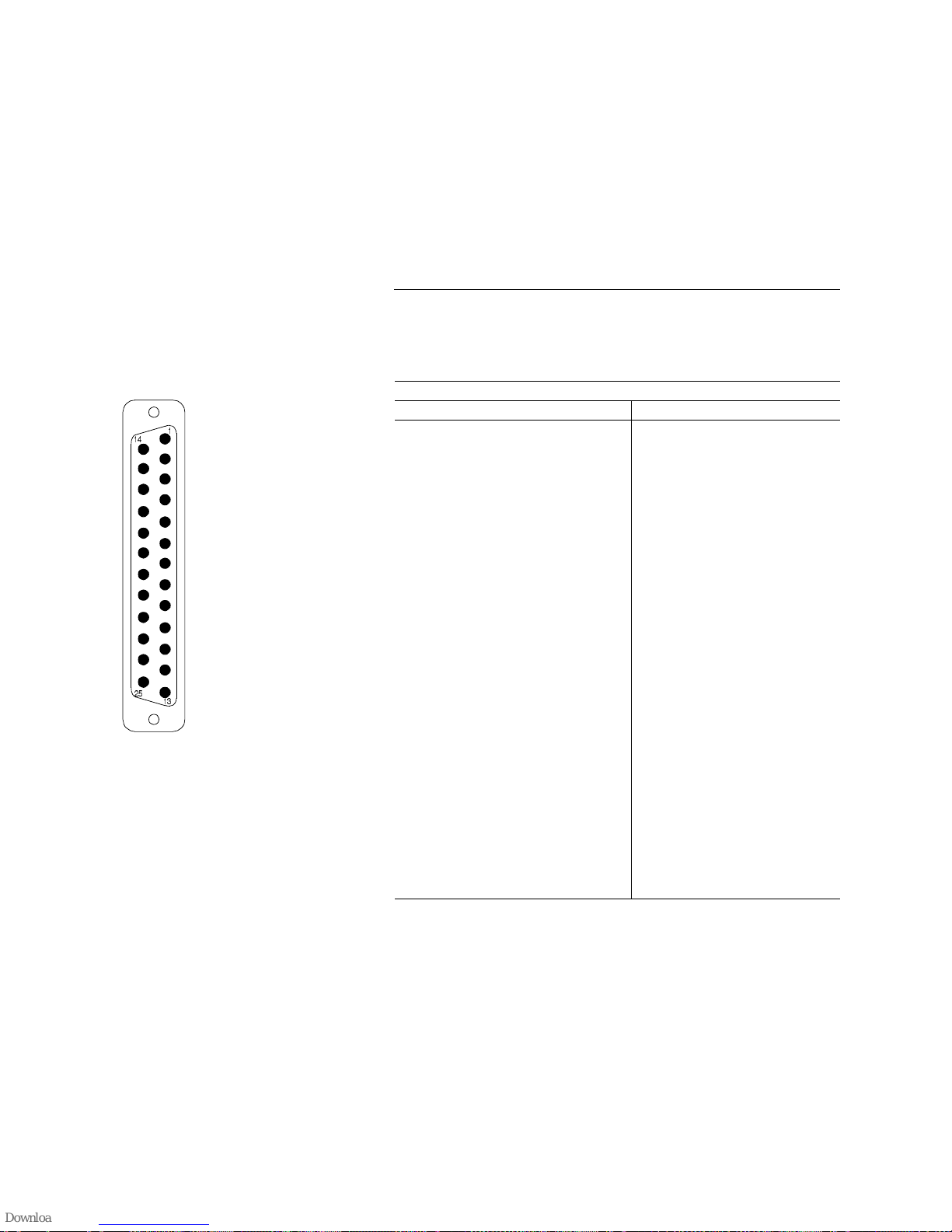
Connector: Extension Bus (25-pole SUB-D)
Pin Signal Electrical characteristics
1
Shield Data rate: 64-kbit/s to 2.048-Mbit/s
(Total data rate with
J.52 data
Level: V.11, symmetrical
Protocol for RS-485:
1 Start bit
8 Data bits
1 Parity bit
1 Stop bit
Data rate: 19200 Bd
2
TXa Transmit Data
3
Ca Control
4
RXa Receive Data
5
CLK48a
a
Clock 256×48 kHz
a Is only used if more than four systems are connected to one bus
6
CLKa Clock Receive
7
8
GND Ground
9
TXb Transmit Data
10
Cb Control
11
RXb Receive Data
12
CLK48b
a
Clock 256×48 kHz
13
CLKb Clock Receive
14
CTa Control RS485-Bus
15
CTb Control RS485-Bus
16
C_DATAa RS485-Bus
17
C_DATAb RS485-Bus
18
RXD_Va Receive_D_Valid
19
RXD_Vb Receive_D_Valid
20
TXD_Va Transmit_D_Valid
21
TXD_Vb Transmit_D_Valid
22
FSa Frame_Sync
23
FSb Frame_Sync
24
CLK48a Clock 256×48 kHz
25
CLK48b Clock 256×48 kHz
Page 56
PAGE 56
INTERFACES
A2.2 Audio interfaces
A2.2.1 AES/EBU interface
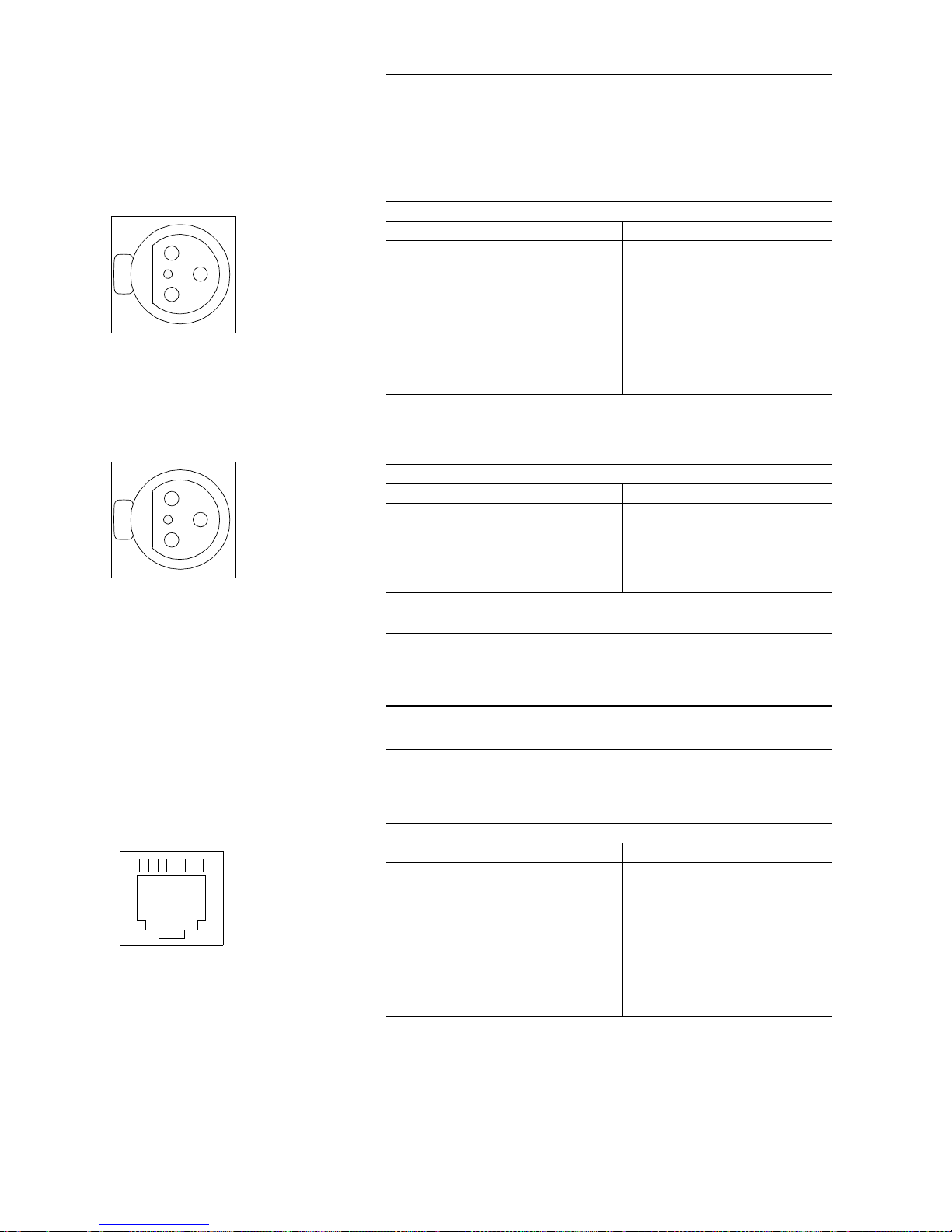
The AES/EBU interfa ce is used for the tra nsmissi on of digital au dio and ad di tional data.
A2.2.2 Analogue Audio interface
Remark
On the analogue unit, centre-tap earthing can be set using
jumpers for the audio signals of the main audio interface. The
jumpers are indicate d on the PCB. In the factor y setting, there
is no centre-tap earthing.
A2.3 Network interfaces
A2.3.1 S o interf aces
A2.3.2 X.21 interfaces
The MAGIC audio system has one X.21 interface available. The X.21 interface allows access to transmission networks is a data interface with bit clock
(a byte clock can be used if it is provided by the network).
Socket: Digital audio interface (XLR)
Pin Signal Electrical characteristics
Input
Level: V.11, symmetrical,
galvanically decoupled
1
GND Shield
2
RXD a Receive Data a
3
RXD b Receive Data b
Output
1
GND Shield
2
TXD a Transmit Data a
3
TXD b Transmit Data b
Socket: Analogue audio interface (XLR
Pin Signal Electrical characteristics
1
Shield Level:
Input –6 dBu to +12 dBu
Output –20 dBu to +12 dBu
Impedance:
Input >12kΩ/600
Ω
Output <20Ω sym.
2
Audio a In or O ut
3
Audio b In or O ut
Socket: 8 pole Western Socket
Pin Signal Electrical characteristics
1
not connected Recommendation: I.430
Bit rate: B Channel: 2x 64-kbit/s
D Channel: 16-bit/s
2
not connected
3
TX
4
RX
5
RX
6
TX
7
not connected
8
not connected
Push
1
2
3
Push
1
2
3
18
Page 57
PAG E 5 7
INTERFACES
In this operating mode, only the “LINE X.21” interface i s available with data rates from 64 to 1920-kbit/s. This is a DTE interface which requires as a transport medium a line in which the data is switched en bloc .
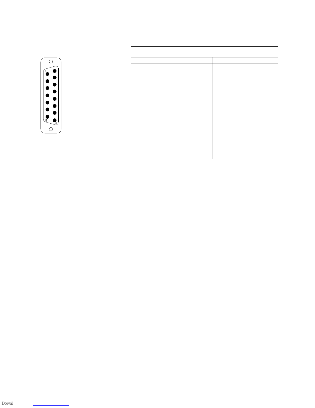
Connector: X.21 Line
(SUB-D 15 pole)
Pin Signal Electrica l characteristics
1
SHIELD Shield Type: DTE
Level: V.11, symmetrical
Data Rat: 64 to 1920-kbit/
Range: 100 m
2
Ta Transmit D ata a
3
Ca Controla
4
R a Receive Data a
5
I a Indicate a
6
S a Signal Element Timing a
7
B a Byte Timing a
8
GND Ground
9
T b Tran smit Data b
10
Cb Controlb
11
R b Receive Data b
12
I b Indicate b
13
S b Signal Element Timing b
14
B b Byte Timing b
15
not connected
Page 58
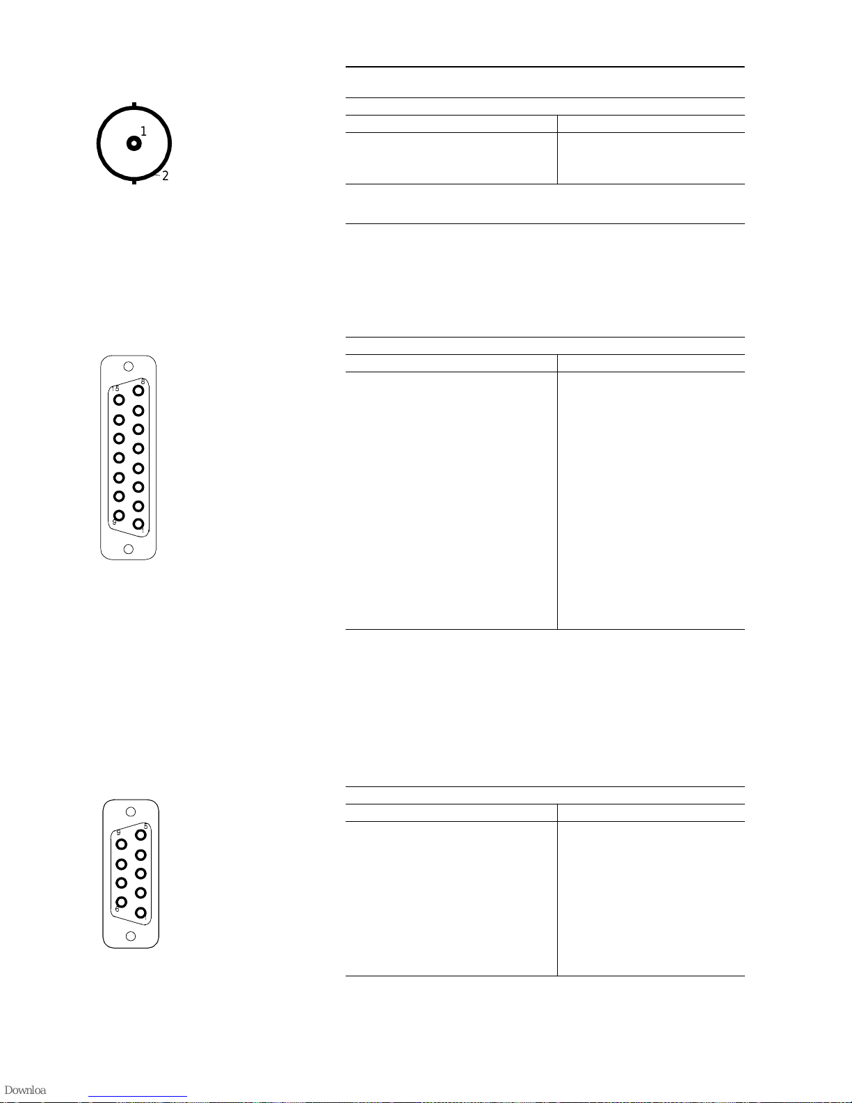
PAGE 58
INTERFACES
A2.4 Sampling clock output
A2.5 Data interfaces
A2.5.1 HSD interface
The HSD channel is inte nded for th e tra nsmissi on of hig h-spe ed da ta. A t pr esent only a data rate of 64-kbit/s is available
A2.5.2 LSD interface
The LSD channel is used for the tran smi ssion of lo w-spe ed data or for the r emote control / diagn osis of the system a t the far (rem ote) end with the J.52 inband signalling protocol. Rem ote contr ol of the far en d system is po ssible between MAGIC systems. A software update of the far end (Remote Software
Update) during transmission has also been implemented.
Socket: Sampling Clock Out (BNC)
Pin Signal Electrical characteristics
1
Clock Amplitude: 0.5 to 1.9 Vp0 (input))
1.5 Vp0 (output)
Impedance : 75Ω, unsym.
2
GND
Socket: HSD (SUB-D 15-pole)
Pin Signal Electrical characteristics
1
SHIELD Schirm Type: DCE
Type: V.11, symmetrical
Data rate: 64 to 1536-kbit/s
Range: 100 m
2
Ta Transmit a
3
Ca Controla
4
R a Receive a
5
I a Indicate a
6
S a Signal Element Timing a
7
B a Byte Timing a
8
GND Ground
9
Tb Transmitb
10
Cb Controlb
11
R b Receive b
12
I b Indicate b
13
S b Signal Element Timing b
14
B b Byte Timing b
15
not connected
Socket: LSD (SUB-D 9pole)
Pin Signal Electrical characteristics
1
CD Carrier Detect Type: DTE
Level: V.24
Data rate: 300 to 38400 Baud
Range: max. 15 m
2
RxD R eceive Data
3
TxD Transmit Data
4
DTR Data Term inal Ready
5
GND Ground
6
DSR Data Set Ready
7
RTS Request To Send
8
CTS Clear to S end
9
RI Ring Ind ication
1
2
Page 59
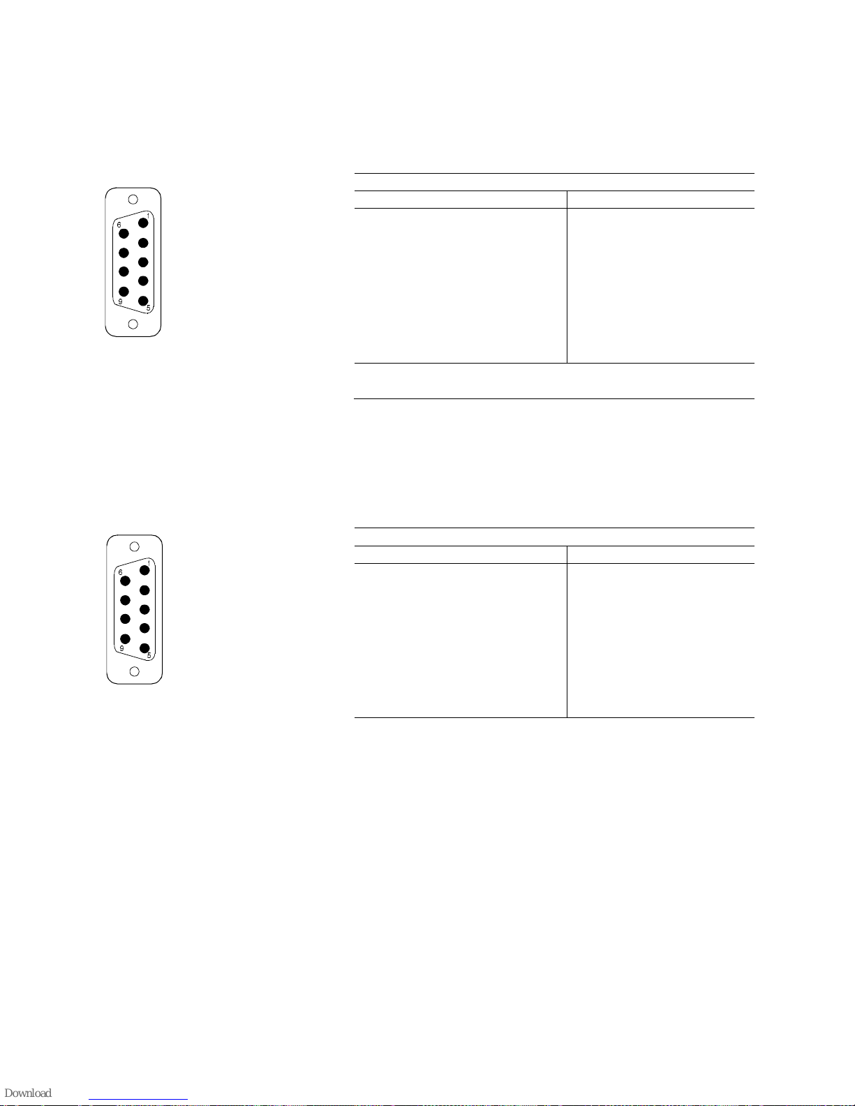
PAG E 5 9
INTERFACES
A2.5.3 Additional Data
The additional da ta interface is for the transmi ssion of program -accompanying
information or RDS da ta. The data is transm itted in a data field in the encoded
audio signal. In the decoder, the additional data is output in parallel with the
audio signal.
A2.6 Operator interfaces
A2.6.1 RS232C and RS232 AUX interfaces
The RS-232C interface is for the configuration and monitoring of the codec
from a PC The RS2 32 AUX in terfa ce i n the S tand ard MAGIC IS DN i s n ot programmed.
Connector: Additional Data Slot 1 – 3 (SUB-D 9 pole)
Pin Signal v
1
Type: DTE
Level: V.24 (RS-23 2C )
Data rate: 300 to 38400 bit/s
Range: max. 15 m
2
RXD Receive Data
3
TXD Transmit Data
4
5
GND Masse
6
7
RTS Request To Send
8
9
Connector: RS-232C (SUB-D 9 pole
Pin Signal Elektrische Eigenschaften
1
not connected Type: DTE
Level: V.24
Data rate: 300 to 38400 Baud
Range: max. 15 m
Protocol: 1 Start bit
7 or 8 Data bits
a
1 Parity bit
b
1 Stop bit
a Factory setting: 8 bits
b the following parities can be set: none, even odd. Factory setting: “none” (no parity)
2
RXD Receive Data
3
TXD Transmit Data
4
DTR Data terminal ready
5
GND Ground
6
DSR Data set ready
7
RTS Request to send
8
CTS Clear to send
9
not connected
Page 60
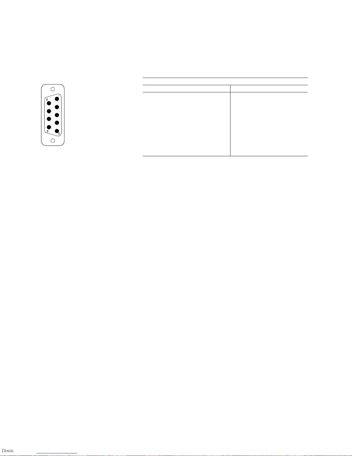
PAGE 60
INTERFACES
A2.6.2 RS485 bus interface
The RS-485 interf ace is a bu s inter face to co nnect sever al C od ecs in a ch ain
and makes it possible to contro l them fr om a P C (th is interfa ce should not be
mistaken for the internal RS 485 interface of the Extension Bus that is used to
configure individual plug-in units (PCBs). In the Standard MAGIC ISDN, this
interface is not programmed.
A2.6.3 User I/O interface
The User-I/O interf ace is com patible w ith the para llel inter face of a PC or pri nter. A log printer can thus be connected without the need for adaptation.
Socket: RS-485 (SUB-D 9-pole
Pin Signal Electrical characteristics
1
SHIELD Type: Bus
Level: V.11, symmetrical
Data rate: 300 to 19200 Baud
Range: 100 m
2
DATA A
3
CONTROL A
4
not connected
5
GND
6
DATA B
7
CONTROL B
8
not connected
9
not connectedt
Page 61
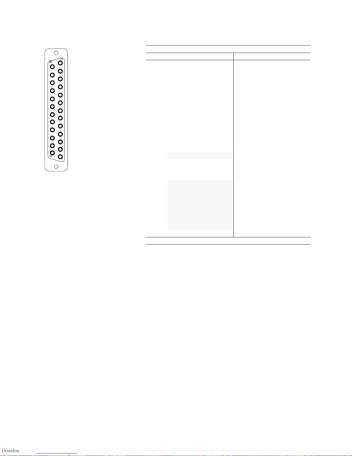
PAG E 6 1
INTERFACES
The interface can also be used to control external equipment. There are 10
outputs, 5 inputs, 8 programmable inputs/outputs, GND and +5V.
Socket: User I/O (SUB-D 25pole)
Pin Signal Electrical Electrical
1
STROBE Out Level: TTL / CMOS
Max. current: 20 mA
2
DATA 0 Out
3
DATA 1 Out
4
DATA 2 Out
5
DATA 3 Out
6
DATA 4 Out
7
DATA 5 Out
8
DATA 6 Out
9
DATA 7 Out
10
ACK In
11
BUSY In
12
PE In
13
SELECT In
14
FEED XT In / Out
15
ERROR In
16
RESET Out
17
+5V/50 mA Out
18
USER 0 In / Out
19
USER 1 In / Out
20
USER 2 In / Out
21
USER 3 In / Out
22
USER 4 In / Out
23
USER 5 In / Out
24
USER 6 In / Out
25
GND
Note: User 0 to 6 and Feed XT can be switched as inputs or outputs
Page 62

PAGE 62
INTERFACES
Page 63

PAG E 6 3
ANNEX3 USER I/O INTERFACE APPLICATIONS
The 25-pole USER I/O interface can be programmed for various different applications. Three different interface modes are available:
– Command mode
– Logic-level transfer mode
– Printer mode
In the command mo de, the USER-I/ O interface sign als can be used to control
the
local
codec. The leading and trailing edges of the si gnal (change of sign al
level from “0” to “1” and vice-versa) are evaluated.
In the logic-level transfer mode, the logic levels at the local inter face are transmitted to the remote end. This can be used to control
external unit s at the
remote e nd
. For operation with the PC, software can be used to set leve ls that
are transmitted to the remote end or which are provided at the USER-I/O interface. Here also, the leading and trailing edges of the signal (change of signal level from “0” to “1” and vice-versa) are evaluated.
In the printer mode, the interface is configured as a Centronics interface. A
printer such as an Epson FX 80 can therefore be connected for log printing
without the need for adaptation.
A3.1 Logic level transfer Mode
To use this operating mode, set the CTRL opera ti ng m ode in th e ope rato r panel (SYS → IFACE → CTRL → TTL). If you are using a PC to control the sy-
stem, set the TTL-INTERFACE MODE switch to LOGIC LEVEL TRANSFER
(in the TTL-INTERFACE panel).
The logic signals fed i n by h ardwa re ( pins 10 , 11, 12, 13 and 15 at the USERI/O interface) are transmitted to the far end and are provided at the outputs
DATA 0 to DATA 4 of the remote USER-I/O interface.
Remark
The default levels at the unconnected outputs (pin 10 to
pin 15) correspond to those of a CENTRONICS printer interface:
Pin Pin
10
ACK +5V
11
BUSY GND
12
PE GND
13
SELECT GND
15
ERROR +5V
Page 64

PAGE 64
USER-I/O INTERFACE APPLICATIONS
Remark
If the pins 10 or 15 are used, th e following cir cuit is recomme nded (it can also be used for the other pins):
If this circuit i s no t u sed, the n t he pin should be con necte d via
the switch to GND. The inverti ng ef fect of th e circuit sho uld b e
noted.
Alternatively, logic levels set by software can be transmitted instead of input
levels at the USER I/O interface. The system must be operated from the PC
for this purpose (see the Software description).
A3.2 Printer mode
T o use t his operatin g mode, set the PRT op erating m ode in the ope rator panel
(SYS → IFACE → CTRL → TTL). If you are using a PC to control the system,
set the TTL-INTERF A CE MODE switch to PRINT ER (in the TTL- INTERF ACE
panel).
The connected unit, e.g. printer, must have a Centronics interface and be capable of processing printer commands for printers such as the Epson-FX80.
GND
Input
(e.g. ACK)
V
cc
1K
Page 65

PAG E 6 5
ANNEX4 LIST OF THE ALARMS
The following alarms can be displayed in the ALARM LIST panel:
TABLE2 FAULT MESSAGES FOR THE LAYER II/III CODECS IN THE ALARM LISTS PANEL
Alarm text Meaning
ENC DSP1 ..DSP4, DEC DSP1 Every signal processor has its own block counter that is polled by the microcontroller. If this value is not incremented by the
DSP every second, there is a fault in the DSP. The processor is not necessarily defective, the software could have crashed.
During the synchronisation phase, this fault message can appear briefly.
DSP HOST ERROR The communication between microcontroller and a signal processor is faulty.
SLOT ERR O R A fault occurred dur in g t he assignm ent of timeslot s to be occupi ed.
DECODER NOT SYNCED The synchronisation with the MPEG audio data stream is faulty.
RS485 The communication between In t erface Unit <-> Codec(s ) is faulty. A received co nfiguration message is f aulty. For certain user
entries (such as switch sine generator on/off or SAVE ON BOARD in the AUDIO panel) this fault message can be ignored.
NO COMMUNICATION This message is generat ed b y the Interf ace Unit and means that the I nterface Unit cannot com m unicate with t he codec. If this
fault should persist (> 1 min.) the unit must be switched off.
WRONG SAMPLING CLOCK The set sampling frequency is not the same as the sampling frequency of the received input data stream. This me ssage is, fo r
example, output if a CD player (44.1 kHz) is connected to the digital input but a sampling frequency of 48 kHz has been set.
From soft ware versi on 4.0, thi s m essage is us ed for the a ut omatic setting of t h e sampling frequency. If this fa ul t occurs even if
the analogue input is being used, then the network clock probably varying considerably. This fault always leads to loss of syn-
chronism in the decoder.
AES/EBU IN The AES/EBU receiver is receiving either a faulty audio signal or no audio signal.
LEVEL IN/OUT L/R In the past minute, the audio signal has not exceeded a specific signal level.
FEPROM1/2 The Flash EPROMs cannot be written to (e.g. during software download). If this fault occurs, software cannot be downloaded
to the codec.
EEPROM The configuration data cannot be read or stored.
RAM Access to the RAM is faulty.
NO CORRECT CODEC SW The software download was faulty.
Page 66

PAGE 66
LIST OF THE ALARMS
 Loading...