

Page 1

MAGIC DC7
Dual 7-kHz Audio Codec
MAGIC AC1
ISDN Audio Codec
Hardware/Software Manual
Page 2

.
Page 3

MAGIC DC7 & MAGIC AC1
ISDN Audio Codecs
Hardware/Software Manual
To get always information on the latest software
please register on our Homepage:
http://www.avt-nbg.de
First click on the menu item Service and then select
Software Registration. Please select as product
MAGIC DC7
or
MAGIC AC1
and enter your contact details. You need to indicate a
valid email address at least.
Page 4

Page 5

A publication of:
AVT Audio Video Technologies GmbH
Nordostpark 12
90411 Nuernberg, Germany
Phone +49-911-5271-0
Fax +49-911-5271-100
Printed in Germany, August 2012
© AVT Audio Video Technologies GmbH
All rights reserved. Reproduction in
whole or in parts is prohibited without the
written consent of AVT Audio Video
Technologies GmbH.
Subject to changes.
Release date: (08.12)
Page 6

.
Page 7

Content
CONTENT 7
INTRODUCTION 11
SAFETY 13
Introduction 13
General safety requirements 13
Text Conventions 13
1CONSTRUCTION15
2 SYSTEM DESCRIPTION 17
Content
2.1 Functionality 18
3 PUTTING THE MAGIC DC7/AC1 INTO OPERATION 19
3.1 Mounting 19
3.2 Connection to the mains voltage 19
3.3 Earthing of the system 20
3.4 Operational elements on the front side 20
3.5 Operating modes of the system 21
3.5.1 Analogue POTS operation 21
3.5.2 ISDN operation 22
4 OPERATION VIA DISPLAY AND KEYPAD 23
4.1 Basic configuration 23
4.1.1 Keypad lock 23
4.1.2 Setting the menu language 23
4.1.3 Setting the operating mode: Analogue POTS or ISDN 24
4.1.4 Setting the Audio interface: Analogue or digital 24
4.2 Working with MAGIC DC7/AC1 26
4.2.1 Calling a partner 26
4.2.2 B channel connections (only in ISDN mode) 26
4.2.3 The Status Display - Operation during a connection 27
4.2.4 Dropping a connection 28
4.2.5 Accepting a call 28
4.3 Comfort Functions 29
4.3.1 Redialling 29
Page 8

Content
4.3.2 Using the phone book 29
4.3.3 Working with Presets 30
4.3.4 Configuration of the Audio sources 31
5 WINDOWS PC SOFTWARE 33
5.1 Hardware requirements 33
5.2 User Registration 33
5.3 Installing the Windows PC Software 34
5.4 Software update from the internet 34
5.5 Configuration and control with the Windows PC Software 35
5.5.1 The MAGIC DC7/AC1 main window 35
5.5.2 Connection status 36
5.5.3 Operating elements 37
5.5.3.1 Audio mixer to select sources and output equipment 43
5.5.3.2 Telephone book 45
5.6 Menu File 47
5.6.1 Submenu Phone Book 47
5.6.2 Submenu Operation Settings Presets 48
5.6.3 Submenu User Transmission Modes 48
5.6.4 Submenu System Settings 48
5.6.5 System Log File 49
5.6.6 Submenu Exit 50
5.7 Menu Configuration 51
5.7.1 Submenu COM Port 51
5.7.2 Submenu MAGIC DC/AC1 52
5.7.2.1 Operation Settings 52
5.7.2.1.1 Line Interface 52
5.7.2.1.2 Data Interfaces 57
5.7.2.1.3 Backup 58
5.7.2.1.4 Functions in the main window with activated backup 60
5.7.2.1.5 Security 62
5.7.2.2 Transmission 63
5.7.2.2.1 Transmission Modes 64
5.7.2.2.2 User Defined 68
5.7.2.3 Basic Settings 72
5.7.2.3.1 General 72
5.7.2.3.2 Audio Interface 74
5.7.2.3.3 Headset Interface 76
5.7.2.3.4 Relay/TTL 78
5.7.2.3.5 Remote Control 84
5.7.2.3.6 Quick Dial 86
5.7.2.4 Date and Time 87
5.7.2.5 Login 88
5.7.3 Submenu Presets 90
Page 9

5.7.3.1 Save as ... 90
5.7.3.2 Manage Presets 90
5.7.3.3 Activate a Preset 92
5.8 Menu Administration 93
5.8.1 Submenu Registration 93
5.8.2 Submenu USB Dongle Information 94
5.8.3 Submenu Remote Control 95
5.8.4 Submenu File System 96
5.8.5 Submenu System Panel 97
5.8.6 Submenu Firmware Download 98
5.8.7 Submenu Create 15-kHz Telephone Mixer Presets 99
5.8.8 Submenu Set Factory Settings 100
5.9 Menu Extras 101
5.9.1 Submenu System Monitor 101
Content
5.9.2 Submenu Audio Mixer 103
5.9.3 Submenu S0 Monitor 104
5.10 Menu Help 105
5.10.1 Submenu About MAGIC DC7/AC1 105
6 OPTION: MAGIC DC7/AC1 KEYPAD 107
6.1 MAGIC DC7/AC1 Keypad Basic 107
6.2 MAGIC DC7/AC1 Keypad Advanced 108
6.3 Functions of the Keypad 109
6.4 ISDN alarm messages in the display 113
7 OPTION: MIXER TOOL PLUG-IN 115
8 OPTION: REMOTE CONTROL SOFTWARE 117
8.1 Remote configuration of a MAGIC DC7/AC1 System 117
8.2 The integrated S0 Monitor 120
9 OPTION: MAGIC DC7/AC1 LAN 123
10 OPTION: SECURITY 125
A1 MENU STRUCTURE 127
A1.1 System Settings 128
A1.2 Operation Settings 130
A1.3 Presets 132
A1.4 Status Information 133
A1.5 Login 134
A1.6 Names 135
A2 THE AUTO DYNAMIC SYNC PROCEDURE 137
Page 10

Content
A3 LIST OF THE TRANSMISSION MODES 138
A4 TROUBLE SHOOTING 139
A5 INTERFACES 140
A5.1 ISDN and analogue telephone interfaces 141
A5.1.1 S0 interface 141
A5.1.2 POTS interface 141
A5.2 Control and data interfaces 142
A5.2.1 CTRL/DATA interface 142
A5.3 Audio interfaces 144
A5.3.1 Analogue Audio interface 144
A5.3.2 Digital AES/EBU Audio interface 144
A5.4 Headset/Micro Audio interface 145
A5.5 Power supply interface 146
A6 TECHNICAL DATA MAGIC DC7/AC1 147
A7 TECHNICAL DATA MAGIC DC7/AC1 KEYPAD 148
A7.1 Keypad 148
A7.2 LCD Display 148
A7.3 Connecting cable 148
A7.4 Connection to power supply (1) 149
A7.5 Connection to MAGIC DC7/AC1 (2) 149
A7.6 Data connection to Keypad (3) 149
A7.7 External power supply 150
A8 GENERAL 151
A8.1 Ordering numbers 151
A8.2 Scope of delivery 151
A8.3 Declaration of Conformity 152
A9 SERVICE INFORMATION 153
A9.1 Software Updates 153
A9.2 Support 153
A9.3 Repairs 153
INDEX 155
DECLARATION OF CONFORMITY 161
Page 11

Introduction
INTRODUCTION
The system MAGIC DC7/AC1 is implemented as portable ISDN Audio Codec
and has analogue and digital AES/EBU Audio interfaces.
In addition to the ISDN interface for Audio coding of higher quality, the system also incorporates a POTS telephone interface whereby at least an Audio
transmission in 3.1-kHz telephone quality is possible, if ISDN is not available.
The configuration of the system can be carried out via the Windows application software included in delivery or via the front keypad of the unit. Optionally, the MAGIC DC7/AC1 Keypad is available for separate operation without
PC.
English
Deutsch
Menu
Select
System Settings
System Settings
Language
Language
Cap
Ok
Save settings?
Yes
No
Operation Settings
Select
Mode
ISDN
Analogue POTS
Audio
Audio Settings
Audio Settings
Audio input
Audio output
Analogue
Digital
PRETALK Interface
No system
Telephone
Handset
Delete
Opt.
ON AIR
HOLD
PRETALK
Dialling...
Callin
Beendet
Line
Ringing Tone
Search
Names
New Entry
Edit
PAGE 11
Page 12

Introduction
Display
Delete entry
Save as Quick Dial
Presets
Load
New
Save
Delete Preset
Ringing Tone
Signal Processing
Keypad 9600, none
Status information
Login
Shift
PAGE 12
Page 13

Safety
SAFETY
Introduction
The unit described has been designed to the latest technical parameters and
complies with all current national and international safety requirements. It
operates on a high level of reliability because of long-term experience in development and constant and strict quality control in our company.
In normal operation the unit is safe.
However, some potential sources of danger for person, material and optimal
operation remain - especially if daily routine and technical errors coincide.
This manual therefore contains basic safety instructions that must be observed during configuration and operation. It is essential that the user reads
this manual before the system is used and that a current version of the manual
is always kept close to the equipment.
General safety requirements
To keep the technically unavoidable residual risk to a minimum, it is absolutely necessary to observe the following rules:
– Transport, storage and operation of the unit must be under the permissible
conditions only.
– Installation, configuration and disassembly must be carried out only by
trained personnel on the basis of the respective manual.
– The unit must be operated by competent and authorised users only.
– The unit must be operated in good working order only.
– Any conversions or alterations to the unit or to parts of the unit (including
software) must be carried out by trained personnel authorised by the manufacturer. Any conversions or alterations carried out by other persons lead
to a complete exemption of liability.
– Only specially qualified personnel is authorised to remove or override
safety measures, and to carry out the maintenance of the system.
– External software is used at one’s one risk. Use of external software can af-
fect the operation of the system.
– Use only tested and virus-free data carriers.
Text Conventions
In this manual the following conventions are used as text markers:
PAGE 13
Page 14

Sicherheit
Accentuation: Product names or important terms
LCD Text
PC Text: Labelling in the PC Software
TIP
NOTE
ATTENTION The symbol ATTENTION marks very important advice that is absolutely to
The symbol TIP marks information which facilitates the operation of the sys-
tem in its daily use.
The symbol NOTE marks general notes to observe.
observe. In case of non-observance malfunctions and even system errors are
possible.
: Labelling on the front display of the system
!
PAGE 14
Page 15
1 CONSTRUCTION
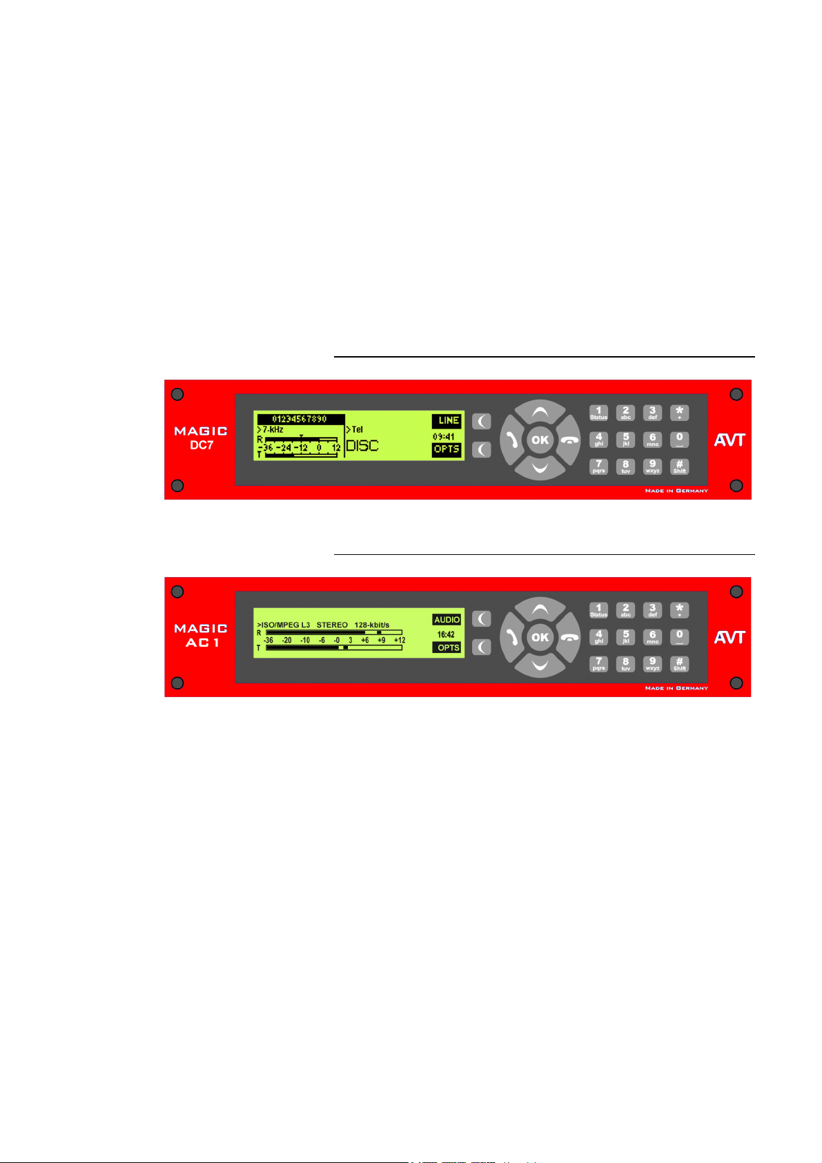
The functions of the MAGIC DC7 are implemented in a single unit. The MAGIC AC1 is additionally equipped with a module for MPEG Coding. The sys-
tem is designed for mounting in a half 19" rack (1 U).
Optionally, a MAGIC DC7/AC1 DUAL 19“ Mounting Kit (ID: 800212 (DC7)
and ID: 800232 (AC1)) is available for the installation of two MAGIC DC7/AC1
Systems next to each other.
FIG. 1 FRONT VIEW: MAGIC DC7 DUAL 7-KHZ AUDIO CODEC
Construction
FIG. 2 FRONT VIEW: MAGIC AC1 ISDN AUDIO CODEC
PAGE 15
Page 16

Construction
PAGE 16
Page 17
2 SYSTEM DESCRIPTION
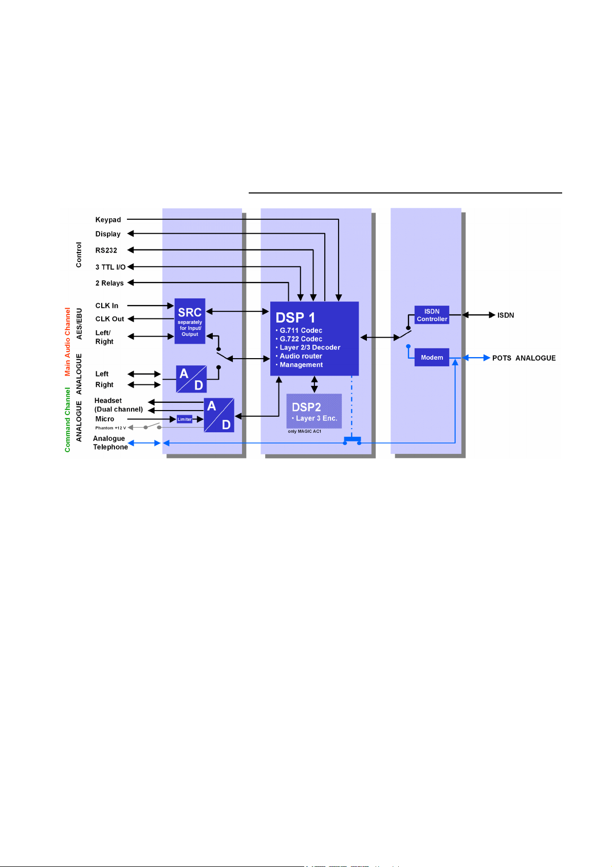
The functional elements of the system are pictured in Fig. 3.
FIG. 3 FUNCTIONAL ELEMENTS MAGIC DC7/AC1 ISDN AUDIO CODEC
System Description
PAGE 17
Page 18

System Description
2.1 Functionality
The MAGIC DC7/AC1 System incorporates an analogue POTS interface as
well as an ISDN telephone interface. The operating modes can be configured
by software. If the ISDN interface is used, depending on the operating mode
two independent channels are available that can be used independently from
each other.
The complete signal processing is taken over by two digital signal processors.
In this way the following functions are realised:
DSP1:
– G.711 Audio encoding and decoding
– G.722 Audio encoding and decoding
– ISO/MPEG Layer II/III Decoder
– digital Audio router, digital Audio mixer (optional)
– Signalling management (J.52, proprietary modes)
– Control of the complete system (Keypad, display, relays, TTL, RS232)
DSP2:
– ISO/MPEG Layer III Encoder (only for MAGIC AC1)
Via the main Audio channel the high quality Stereo or Mono Audio signal is
inserted or output analogue or digitally. At the same time, the command
channel can be used in parallel. If the digital AES/EBU Audio interface is
used, two separate Sample Rate Converters are available for automatic clock
synchronisation. For external clocking a clock input and a clock output are
available.
Additionally, the Audio Codec incorporates a Headset interface for Stereo
tone or Dual Channel tone with a microphone input, Limiter and 12V phantom power which can be switched off.
By the integrated Audio router all input and output signals can be configured
freely. If you use the optional Software Plug In MAGIC DC7/AC1 Mixer Tool,
even all signals can be mixed in a flexible way.
The configuration and operation can be carried out via the front keypad and
the illuminated display.
Configuration and control is especially comfortable with the MAGIC
DC7/AC1 Windows PC Software which is included in delivery and which
communicates with the system via the RS232 interface.
PAGE 18
The basic operating functions like accepting a call, dropping a connection and
establishing a connection with a pre-programmed number can be carried out
via three programmable TTL contacts. Two relays are available for status indication.
Optionally, the system can also be operated separately via the MAGIC
DC7/AC1 Keypad that can be connected to the RS232 interface instead of the
PC Software.
Page 19

Putting the system into operation
3 PUTTING THE MAGIC DC7/AC1 INTO
OPERATION
3.1 Mounting
With its dimensions (W × H × D) of 220 mm × 44,5 mm (1 U) × 220 mm the
MAGIC DC7/AC1 System can be used either as desktop device or mounted in
19 inch racks. Corresponding 19“ mounting brackets are included in delivery.
Optionally, a mounting kit (ID: 800202) to install two MAGIC DC7/AC1 next
to each other
When mounting the unit please keep in mind that the bending radius of the
cables is always greater than the minimum allowed value.
1
is available.
When the MAGIC DC7/AC1 Audio Codec is installed, please make sure that
there is sufficient ventilation: It is recommended to keep a spacing of ca. 3 cm
from the openings. In general, the ambient temperature of the system should
be within the range of +5°C and +45°C. These thresholds are especially to observe if the system is inserted in a rack. The system works without ventilation.
TIP
ATTENTION Incorrect ambient temperature and humidity can cause functional defi-
!
3.2 Connection to the mains voltage
The system temperature can be indicated on the display (
mation
(see CHAPTER A1.4, Page 133))
During operation air humidity must range between 5% and 85%.
ciencies
Operation outside the threshold values indicated above leads to a loss of warranty claim.
The system can be operated with mains voltages in the range from 90 V to
253 V via the external power supply included in delivery. The line frequency
can vary from 45 Hz to 65 Hz. The maximum power consumption is 15W. The
rack must be earthed according to the VDE Regulations. The earthing can be
carried out via the earthing screw on the back side of the unit.
Menu Status infor-
The unit does not have a circuit closer and a circuit breaker. After plugging in
the external power supply the system boots within a few seconds. In stand-by
mode the AVT logo is shown on the display
1
Likewise the DC7/AC1 can be combined with the product MAGIC TH2.
2
Depending on the delivery status all menus are possibly displayed in German. The configuration
of the menu language is described in CHAPTER 4.1.2.
2
.
PAGE 19
Page 20
Inbetriebnahme
3.3 Earthing of the system
For EMC reasons an earthing via the earthing screw of the system must be carried out in either case.
ATTENTION Earthing
A lacking earthing can cause functional deficiencies within the unit.
!
3.4 Operational elements on the front side
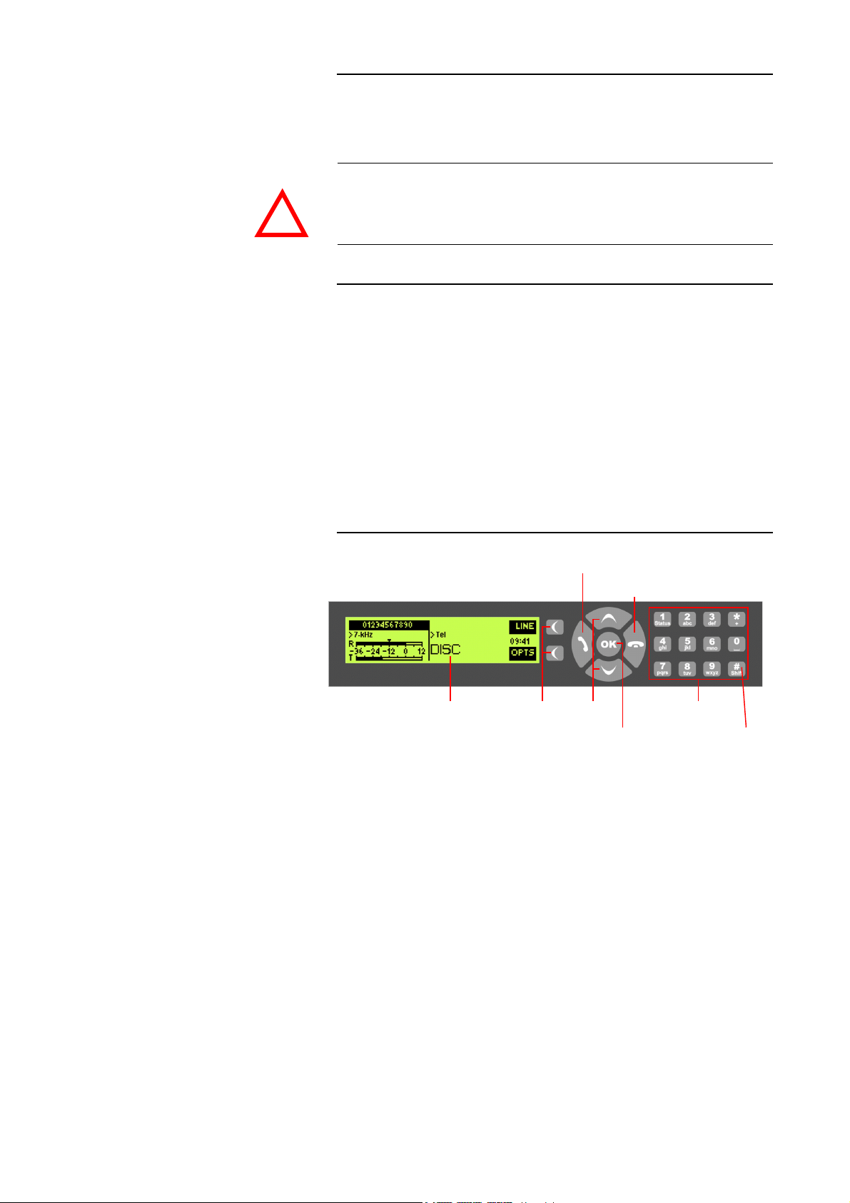
The system has an illuminated graphical display with a resolution of 160 x 32
Pixels and 21 operating buttons.
On the right next to the display there are two softkeys whose current functions are indicated on the display. In the middle there are two cursor buttons
(upwards/downwards), two buttons for accepting/dropping calls as well as
an
OK
button. The numerical pad supports in addition to the numerical char-
acters
0...9
, the ’*’ and ’#’ key. For text entries the numerical pad can also be
used as normal keypad.
The operation is similar to standard mobile telephones.
FIG. 4 OPERATIONAL ELEMENTS ON THE FRONT SIDE
Establish connection
Graphical
display
Accept call
Softkeys Cursor
buttons
Drop/
Main menu
Confirm
entry/
Status window
Keypad for
dialling/ text entry
B channel
(only ISDN)
shift
PAGE 20
Page 21
3.5 Operating modes of the system
The figures below show the systems in the different operating modes and
their wiring.
3.5.1 Analogue POTS operation
ATTENTION Earthing
If the analogue POTS interface is in operation the system must be earthed via
earthing screw for EMC reasons. If the earthing is not carried out, the Audio
!
signal can be faulty on the caller’s side (humming).
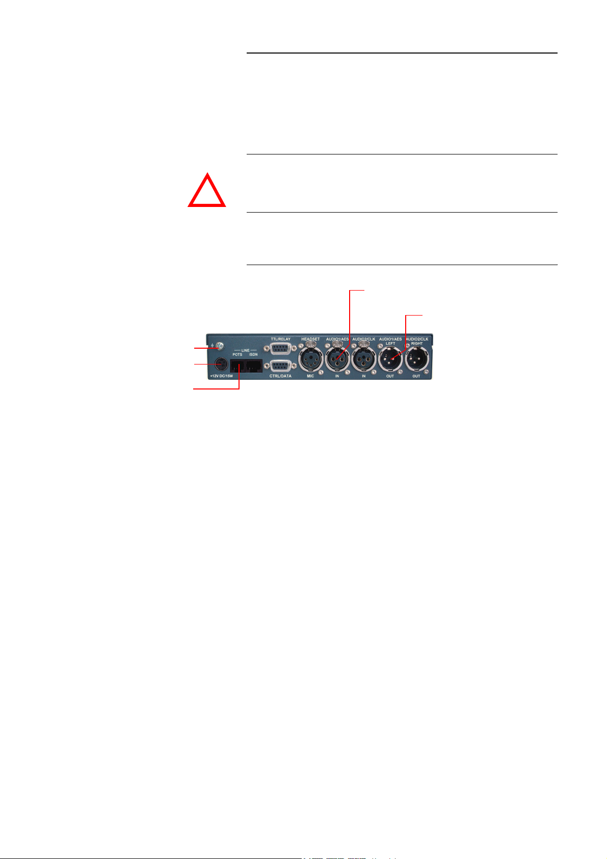
The minimum wiring for the operation with an analogue telephone line is pictured in Fig. 5.
FIG. 5 MINIMUM WIRING FOR ANALOGUE POTS OPERATION
Analogue Audio 1 (left)/(AES/EBU) Input
Inbetriebnahme
Analogue Audio 1 (right)/(AES/EBU) Output
Earthing!
Power supply
interface
POTS
telephone
interface
PAGE 21
Page 22
Inbetriebnahme
Power supply
3.5.2 ISDN operation
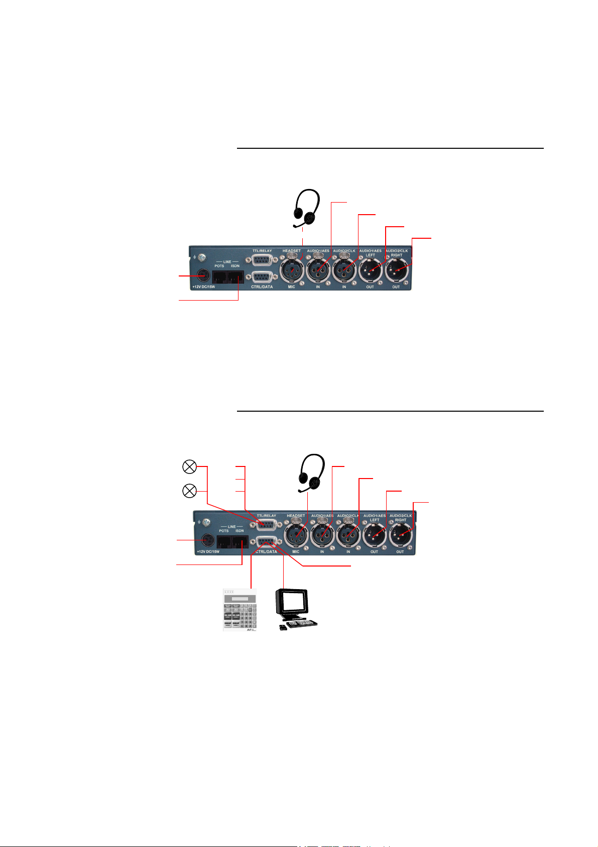
In contrast to the analogue POTS operating mode, in the ISDN operating
mode two independent B channels are available which can be used separately
for mono transmissions or in combination for a stereo transmission.
For live reports a professional Headset can be connected.
FIG. 6 MINIMUM WIRING FOR ISDN OPERATION
interface
ISDN
interface
Option:
Headset
Analogue Audio 1 (left)/(AES/EBU) Input
Analogue Audio 2 (right)/(clock) Input
Analogue Audio 1 (left)/(AES/EBU) Output
Analogue Audio 2 (right)/(clock) Output
Programmable
relays
REL1
REL2
Power supply
interface
ISDN
interface
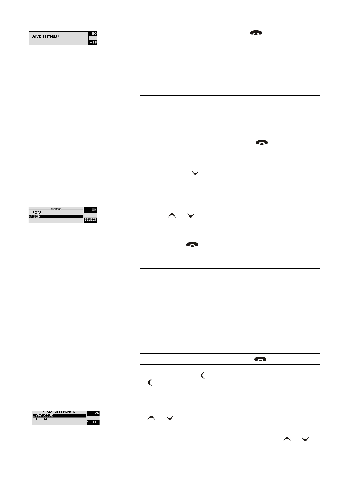
The maximum wiring with all options is shown in Fig. 7. Via the RS232 control interface a PC with MAGIC DC7/AC1 Software or a MAGIC DC7/AC1
Keypad can be connected as alternative to the operation by the front keypad
and display.
FIG. 7 MAXIMUM WIRING FOR ISDN OPERATION
Programmable
TTL Inputs/Outputs
TTL1
TTL2
TTL3
MAGIC DC7/AC1
Hybrid Keypad
Option:
Headset
PC with Option:
MAGIC DC7/AC1
Software
Analogue Audio 1 (left)/(AES/EBU) Input
Analogue Audio 2 (right)/(clock) Input
Analogue Audio 1 (left)/(AES/EBU) Output
Analogue Audio 2 (right)/(clock) Output
2 x transparent
data channels
(RS232 or RS485)
PAGE 22
Page 23

Operation via Display and Keypad
4 OPERATION VIA DISPLAY AND KEYPAD
In this chapter all basic configurations for the operation of the MAGIC
DC7/AC1 system are explained. An overview of the menu structure you will
find in the annex under CHAPTER A1.
Of course, all configurations can also be comfortably made via the MAGIC
DC7/AC1 Software included in delivery.
Menu reference number
NOTE
4.1 Basic configuration
NOTE
4.1.1 Keypad lock
For the details of most functions please see the PC Software description from
CHAPTER 5.
In the following, some specific basic configuration of MAGIC DC7/AC1 are
described in detail. The configurations for MAGIC DC7 and MAGIC AC1 differ only in a few aspects. Major differences are marked in the text.
All menus can be reached directly via a QuickMenu key sequence. For this
purpose each menu item is marked with a cypher in the upper left corner (in
the example on the left it is e. g.
enter from the main menu the key sequence
<digit> marks the respective menu reference number. Please notice that the
menu reference number can change depending on the configuration.
To avoid that keys are pressed accidentally, you can enable a keypad lock. For
activation please press the
pad lock is enabled, the display illumination is turned off immediately.
3
). To reach a certain menu directly please
Menu <DIGIT> <DIGIT>
Menu
key followed by the * (star) button. If the key-
whereby
The keypad lock is deactivated by entering the key sequence
time.
4.1.2 Setting the menu language
NOTE
In delivery status
Deutsch
If you are not in the main menu please press the key first.
First press the softkey
Select
in the menu. Via the
sired language. With the help of the cursor keys and please choose the
language and press again
Please confirm your entry by pressing the
as menu language please follow the instructions below:
. Press the cursor key once until the option
English
Menu
Select
Menu
a second
*
is selected as standard menu language. To select
and select
softkey you directly reach the options for the de-
Select
.
System Settings
using the softkey
Language
Ok
button or the Ok softkey.
is displayed
PAGE 23
Page 24
Operation via Display and Keypad
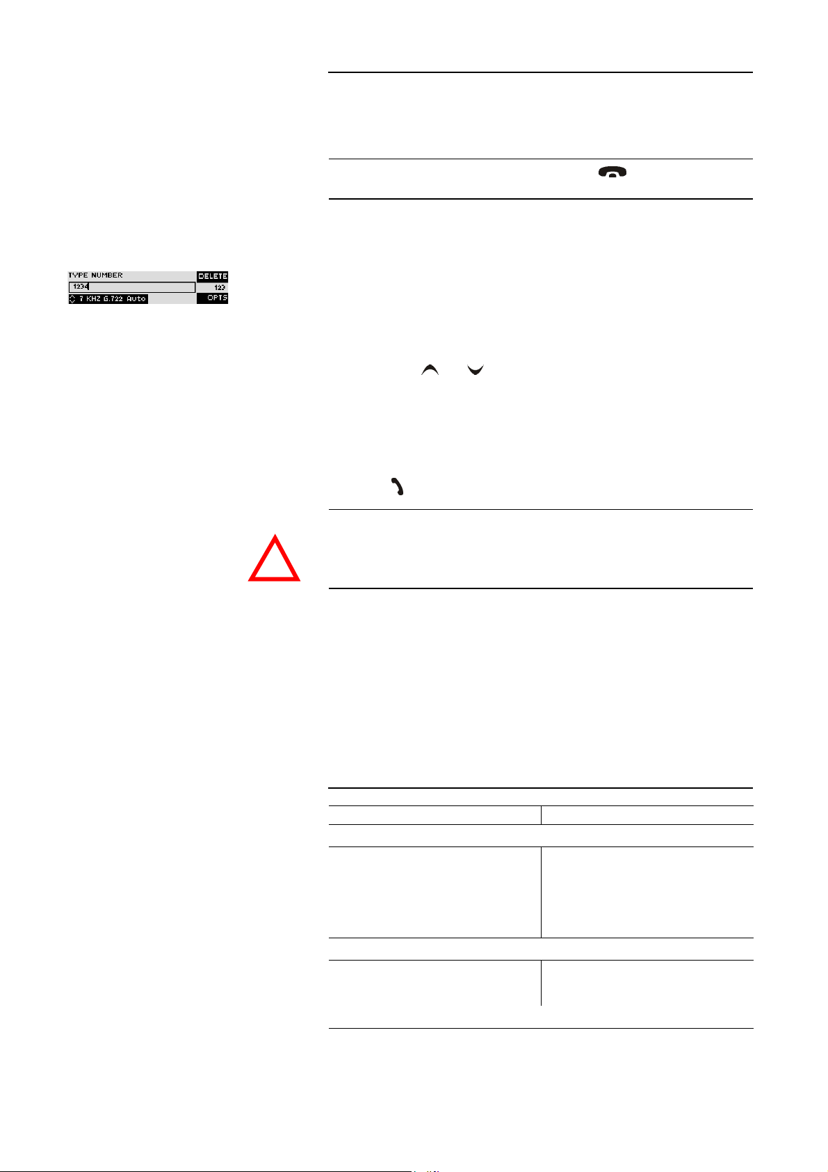
To get back to the main menu, please press the key. Now you are asked
if you want to
manently in the system.
Save settings?
. Via the
Yes
softkey the settings are stored per-
NOTE
TIP
4.1.3 Setting the operating mode: Analogue POTS or ISDN
NOTE
If you press No, all settings that you made are lost when the unit is switched
off.
You reach the settings for the
To set the operating mode POTS or ISDN the following steps are required:
If you are not in the main menu, please press the key first.
– Press the softkey
– Via the cursor key please select the option
press the softkey
– Press again the softkey
– Now please select the desired operating mode
sor keys and and confirm your selection with the softkey
– The entry is accepted by pressing the
Menu
Select
.
.
Select
Language
directly via the key sequence:
to get to the menu
Ok
Operation Settings
Mode
ISDN
button or the softkey Ok.
or
.
POTS
using the cur-
Menu 1 9
and
Select
.
– Please press the button to get back to the main menu. Now you are
asked if you want to
stored permanently in the system.
TIP
4.1.4 Setting the Audio interface: Analogue or digital
NOTE
You reach the settings for the
MAGIC DC7/AC1 incorporates analogue as well as digital Audio interfaces
which you can adjust separately. The digital AES/EBU interfaces have integrated Sample Rate Converters to adjust the digital Audio source to the transmission clock. Additionally, clock inputs/outputs are also available. To configure the Audio interface please follow the instructions below:
If you are not in the main menu please press the button first.
– First press the softkey
Select
.
– With the use of the
– Please mark the option
and and press again
are displayed.
Save settings?
Mode
Menu
Select
softkey you reach the option
Audio input
Select
. Via the
directly via the key sequence:
and select
or
Audio output
. Now the options
System Settings
Yes
softkey the setting is
via the softkey
Audio Settings
using the cursor keys
Analogue
Menu 2 1
and
Digital
.
PAGE 24
– Select the desired interface with the help of the cursor keys and and
by pressing the softkey
Select
.
Page 25

Operation via Display and Keypad
– Confirm your entry by pressing the Ok button or the softkey Ok.
– To get back to the main menu please press the button. Now you are
asked if you want to
stored permanently in the system.
Save settings?
. Via the softkey
Yes
the setting is
TIP
You reach the settings for the
quence:
Menu 1 1 1
or
Menu 1 1 2
Audio input
or
Audio output
via the key se-
PAGE 25
Page 26
Operation via Display and Keypad
4.2 Working with MAGIC DC7/AC1
In the next chapters basic functions like establishing a connection, dropping a
connection, accepting calls etc. are described in detail.
NOTE
If you are not in the main menu please press the button first.
From the main menu you reach the status window via the
Ok
button.
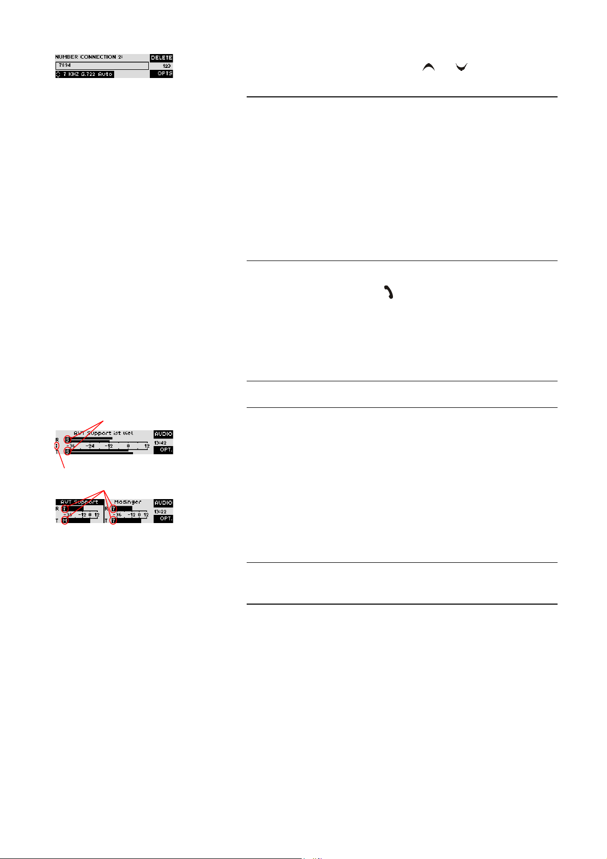
4.2.1 Calling a partner
From the main menu just enter the phone number using the keys
0...9
. The input field for the phone number is displayed automatically after entering the
first cypher.
With the softkey
The cursor keys and allow you to select the transmission mode
Phone
,
7 kHz G.722 (Auto)
(Auto)
), as well as all defined transmission modes (see CHAPTER 5.7.2.2.1).
Delete
wrong entries can be corrected.
(MAGIC AC1 additionally:
Tele-
15kHz 1B (Auto), 15kHz 2B
As soon as the partner accepts the call, the system tries to synchronise the Audio signal in the selected Audio mode.
The connection is established by entering the calling number and pressing the
phone key .
ATTENTION Information about the synchronisation procedure ADS (Auto Dynamic Sync)
can be found in CHAPTER A2, Page 137.
!
Under the softkey
Opt.
(Options) the entered phone number can be saved in
the phone book (see CHAPTER 4.3.1, Page 29) or stored as Quick Dial number
(see CHAPTER 4.3.2, Page 29).
4.2.2 B channel connections (only in ISDN mode)
In the ISDN operating mode two independent Audio codecs respectively a
Stereo ISO/MPEG transmission with 128-kBit/s are available because of the
two B channels. The following modes are possible:
TAB. 1 COMBINED OPERATING MODES
B channel 1 B channel 2
Modes of the MAGIC DC7
Telephone Telephone
7-kHz Telephone
7-kHz 7-kHz
Telephone 7-kHz
Additional modes with the MAGIC AC1
MPEG MONO Telephone
MPEG MONO 7-kHz
MPEG STEREO
PAGE 26
Page 27
Operation via Display and Keypad
To enter a second calling number please press the OK button and enter the second calling number. Using the cursor keys and you can select the desired Audio mode for the second connection.
NOTE
4.2.3 The Status Display - Operation during a connection
TIP
If you choose
need to enter the phone number only once. The system automatically establishes two connections with the same phone number.
If the phone numbers are meant to be different for the first and the second
channel in a stereo connection, you can press the OK button for entering a
second phone number. Alternatively, it is also possible to enter the two
phone numbers separated by the
sufficient to enter as second number only the difference to the first phone
number.
Examples:
0123456789-0123456790
0123456789-90
The connection is established after the entry of the calling numbers by pressing the telephone receiver button .
After the telephone receiver button is pressed the partner is called and the status window is displayed automatically.
The status window can always be reached by pressing the OK button.
MPEG STEREO
(only MAGIC AC1) as Audio mode, you usually
key („-“ character is displayed). It is also
*
Audio mode
Number of connected B channels
Audio mode
NOTE
During a stereo connection the number of the connected B channels is displayed to the left of the level indication.
In the ISDN operating mode the window is split if two independent connections have been established.
To switch between the two connections, please press the
name of the selected channel is displayed inversely.
An outgoing call is signalled by
if a phone book entry is selected) is displayed in the first line.
In the POTS operating mode the phone number or the name is only displayed
for outgoing calls. The CLIP
phone lines.
a CLIP = Calling Line Identification Presentation
When the connection is established the level indication for the incoming signal(
R
eceive) and for the outgoing signal(Transmit) is displayed.
If the Audio connection is synchronised the corresponding Audio coding algorithm is displayed for each channel:
Dialling...
a
function is not supported by analogue tele-
. The dialled number (or the name
Shift
key (#). The
–
T
–
7
–
M
–
S
–
?
Telephone 3.1-kHz
G.722 7-kHz
ISO/MPEG Mono
ISO/MPEG Stereo
no synchronising
PAGE 27
Page 28

Operation via Display and Keypad
By pressing the softkey
which all Audio signals can be selected.
With the use of the softkey
and it is also possible to directly switch to the phone book.
4.2.4 Dropping a connection
The connection is dropped by pressing the telephone receiver button . If
no further connection exists, the main menu is displayed after a few seconds.
NOTE
4.2.5 Accepting a call
NOTE
Please make sure that you have selected the right channel if you want to drop
a connection.
If the MAGIC DC7/AC1 receives a call, it is automatically signalled in the status window by
Additionally, a system ringing tone can be enabled.
The call can be directly accepted with the telephone receiver button .
Callin
Audio
you reach the options for the Audio sources via
Opt.
the displayed phone number can be stored
.
If you want to reject the call, please press the following telephone receiver
button .
PAGE 28
Page 29
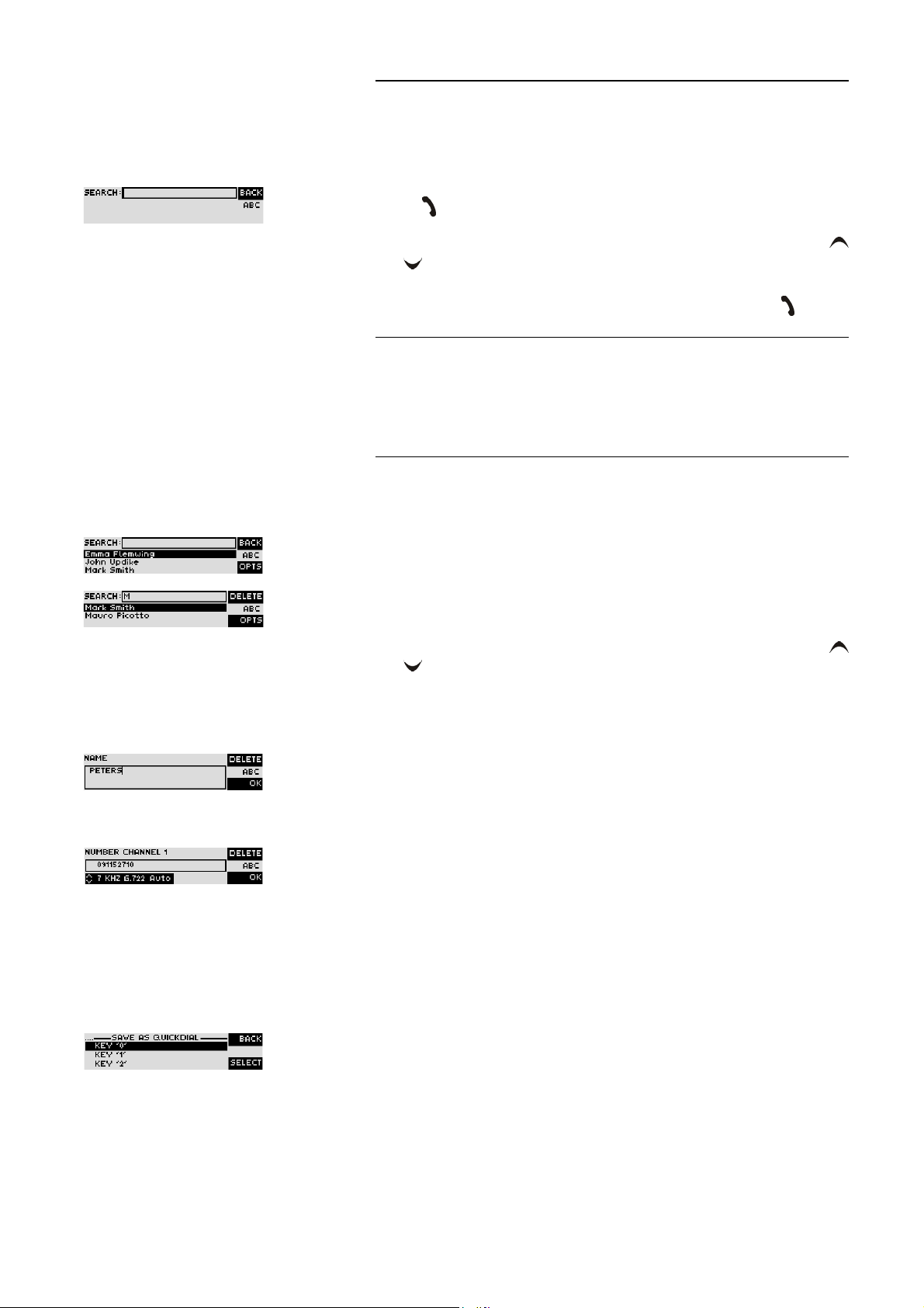
4.3 Comfort Functions
4.3.1 Redialling
You reach the redialling function by pressing again the telephone receiver
button for the line on which no connection currently exists. The recently
called partners are displayed in a list. In the input field
for a certain partner or select a partner from the list using the cursor keys
and
To call a partner please press again the telephone receiver button .
.
Operation via Display and Keypad
Search
you can search
NOTE
4.3.2 Using the phone book
To enter characters you can use the alphanumeric keypad. You reach the desired character by pressing the respective key several times. To type e.g. a ’
you need to press the button ’
the help of the softkey
To switch between upper and lower case please press the
play changes from
The system incorporates a comfortable phone book function. You reach the
phone book from the main menu via the softkey
In the input field
enter a character the corresponding phone book entries are filtered out.
Alternatively, you can select a partner from the list using the cursor keys
and
By the softkey
the softkey
–
.
Select
New Entry
try.
First enter the name and confirm your entry with
ABC
Search
Opt.
(Options) the following functions, which you can select via
, are realised:
: With the help of this function you create a new phone book en-
5
’ twice. Wrong entries can be corrected with
Delete
.
SHIFT
key. The dis-
to abc.
Names
.
you can search for a certain partner. As soon as you
Ok
.
K
’
Then enter the phone number of the partner and select your desired transmission mode with the cursor keys and confirm it as well with Ok.
Edit
: This function allows you to edit already existing phone book entries.
–
Display
–
number.
–
Delete entry
you are asked if you really want to delete the entry.
–
Save as Quick Dial
grammed as Quick Dialling numbers on the numerical keys ’
Please select the key from the list on which you want to programme the
phone number.
: The selected phone book entry is displayed with name and phone
: The selected phone book entry is deleted. For safety reasons
: Your 10 most important phone numbers can be pro-
0
’ ... ’9’.
PAGE 29
Page 30

Operation via Display and Keypad
To activate a Quick Dialling number just press from the main menu the desired Quick Dial key for at least 3 seconds. The connection to the partner is
established automatically.
TIP
4.3.3 Working with Presets
The phone book functions can also be reached directly via the QuickBook
function. Please press the following key sequence:
Example:
The MAGIC DC7/AC1 differentiates between
Settings
System Settings are settings that do not change during normal operation like
e.g. language, date/time etc. These parameters cannot be saved as Preset
since a configuration is usually only required when the system is put into operation.
Operation Settings like e.g. the line interface ISDN or Analogue POTS, Ringing Tone, etc., need to be reconfigured depending on the application. To easily
recall recurring configurations you can store up to 10 Presets in the system.
You reach the menu for the Presets by pressing the
sor key twice and by pressing the softkey
In the input field
enter a character, the corresponding entries of the Preset list are filtered out.
Save as Quick Dial
.
Presets
Names Opt. <DIGIT>
-
Names Opt. 5
System Settings
Menu
Select
once as confirmation.
you can search for a certain Preset. As soon as you
and
Operation
softkey once, the cur-
NOTE
Alternatively, you can select a Preset from the list using the cursor keys
and
If you now press the Ok button, the selected Preset is loaded immediately.
By the softkey
the softkey
–
–
–
–
If the configuration has changed, you are asked if you want to
when you leave the Preset menu. Via the
stored permanently in the system. This Preset is loaded automatically by the
system after the unit is connected to the power supply.
.
Opt.
(Options) the following functions which you can select via
Select
are realised:
Load
: The stored Preset is loaded.
New
: With the help of this function you can create a new Preset. All current
Operation Settings are stored.
Save
: The currently selected Preset is overwritten with the current Opera-
tion Settings. For safety reasons a confirmation is required.
Delete Preset
a confirmation is required.
: The currently selected Preset is deleted. For safety reasons
Save settings?
Yes
softkey the configuration is
PAGE 30
Page 31

Operation via Display and Keypad
4.3.4 Configuration of the Audio sources
TIP
When a connection exists, the
upper softkey via which all Audio sources can be configured. Via the integrated Audio router, each Audio input can be routed to each Audio output
and the headset according to your requirements.
The configuration of the Audio sources is especially comfortable via the Au-
dio Mixer of the PC Software (see CHAPTER 5.9.2).
After the
played for which you can select a source:
Audio
softkey has been pressed, all available Audio outputs are dis-
AUDIO
function is automatically assigned to the
– Source Headset
– Source Audio Out 1
– Source Audio Out 2
– Source transmit ch. 1
– Source transmit ch. 2
The option
both transmit signals
HEADSET MONITOR
allows you to monitor both Audio outputs and
NOTE
Please select the desired Audio interface with the cursor keys and and
press the
Afterwards all available Audio sources for the selected Audio interface are
displayed. The Audio interface can be selected by pressing the
(
#
you can activate (
vated, the current level of the Audio source is displayed and can be adjusted
with the cursor keys and within the range of -16 dB ... +16 dB.
When one of the transmit signal sources (e.g.
lected, the option Auto Ducking (
uration, the Audio signal of the Audio inputs is treated automatically according to the selected Auto Ducking Parameters if the microphone input is used.
If the fee-based software option Mixer Tool Plug-In (see CHAPTER 7) is not
enabled for your system, you can always activate only one Audio source at a
time.
Additionally, you can load or save the Audio interface settings with the options
used.
The Audio interface setting which is stored under the
loaded automatically when the system is switched on.
Select
.
). The currently selected interface is marked by a frame. Via the
ON
) or deactivate (
OFF
) the interface. If an interface is acti-
Source transmit Ch. 1
DCK
) is additionally available. In this config-
Load Audio Preset
and
Save Audio Preset
. In total, three presets can be
STANDARD PRESET
SHIFT
MODE
button
softkey
) is se-
is
With the selection
livery status:
– output 1 = receive signal 1 (RX1)
– output 2 = receive signal 2 (RX2)
– transmit signal 1 = input 1 (IN1)
Default settinGS
, all Audio interfaces are reset to the de-
PAGE 31
Page 32

Operation via Display and Keypad
– transmit signal 2 = input 2 (IN2)
– all other sources are deactivated
Mikrophone muted
NOTE
NOTE
When a Stereo transmission (only MAGIC AC1) is made, the inputs and outputs are combined correspondingly and controlled jointly.
Mute microphone
OK
The microphone can be muted during a connection by pressing the
button.
By pressing the button a second time, you deactivate the muting. In the status
window, a blinking symbol is displayed on the left side next to the level meter.
If connections with two different partners are established, the microphone is
always muted for both connections.
Adjust headphones level
If a headphone is connected to the Headset interface, you can adjust the headphones level with the cursor keys and within the range of -40 dB ... 0
dB during a connection.
Display connection parameters
If the
Status
key (1) is pressed during a connection, the Audio transmission
parameters are displayed.
Display system name
If no connection exists, you can display the system name by pressing the
phone button .
PAGE 32
Page 33

Windows PC Software
5 WINDOWS PC SOFTWARE
The configuration of the system is especially comfortable with the Windows
PC Software included in the delivery.
5.1 Hardware requirements
The PC must meet the following minimum requirements:
– IBM PC AT, IBM PS/2 or 100% compatible
– Pentium Processor (> 500 MHz) recommended
– Windows 2000/XP
– ca. 600 kilobyte available RAM
– 5 MB available hard disk space
– Screen resolution with 800 x 600 Pixels
– at least one available serial interface RS-232
– Microsoft, IBM PS/2 or 100% software compatible mouse
5.2 User Registration
To get always information about the latest software automatically, please register on our Homepage:
http://www.avt-nbg.de
First select the menu item Service and then choose Software Registration. Se-
lect as product
MAGIC DC7
or
MAGIC AC1
– and enter your contact details. You need to indicate a valid email address
at any rate.
PAGE 33
Page 34

Windows PC Software
5.3 Installing the Windows PC Software
Please insert the CD included in delivery in your CD-ROM drive. The software automatically starts your Internet browser. Possible safety warnings can
be ignored for the moment. Please press under Install Software the MAGIC
DC7/AC1 button. Subsequently, the setup program is executed.
Alternatively, you can install the software directly from the CD. You will find
the installation file setup.exe in the folder Software\MAGIC DC7 & AC1 on
the CD.
Please follow the instructions of the installation routine.
After the installation the software can be started by clicking on the MAGIC
DC7/AC1.
Please connect your PC via a serial 1:1 cable (only Pin 2 and Pin 3 are used, Pin
5=ground) with the system.
The standard COM Port settings are: PC (19200 Baud)
5.4 Software update from the internet
Software updates can be down loaded from our homepage
http://www.avt-nbg.de
free of charge. Please go o to the Service section on our webpage and select
Software Download. Under MAGIC Audio Codecs please download the file
with the Id-Nr. 490196. When the download is complete, execute setup and
follow the instructions.
In addition to the PC Software, the setup also includes the firmware for the
system. If it also has to be updated, the MAGIC DC7 & AC1 Software display
an error message when it is started. The instructions for a firmeware update
is described in CHAPTER 5.8.6, Page 98.
PAGE 34
Page 35
Windows PC Software
5.5 Configuration and control with the Windows PC Software
In the following chapters, all functions of the PC Software are described in details.
5.5.1 The MAGIC DC7/AC1 main window
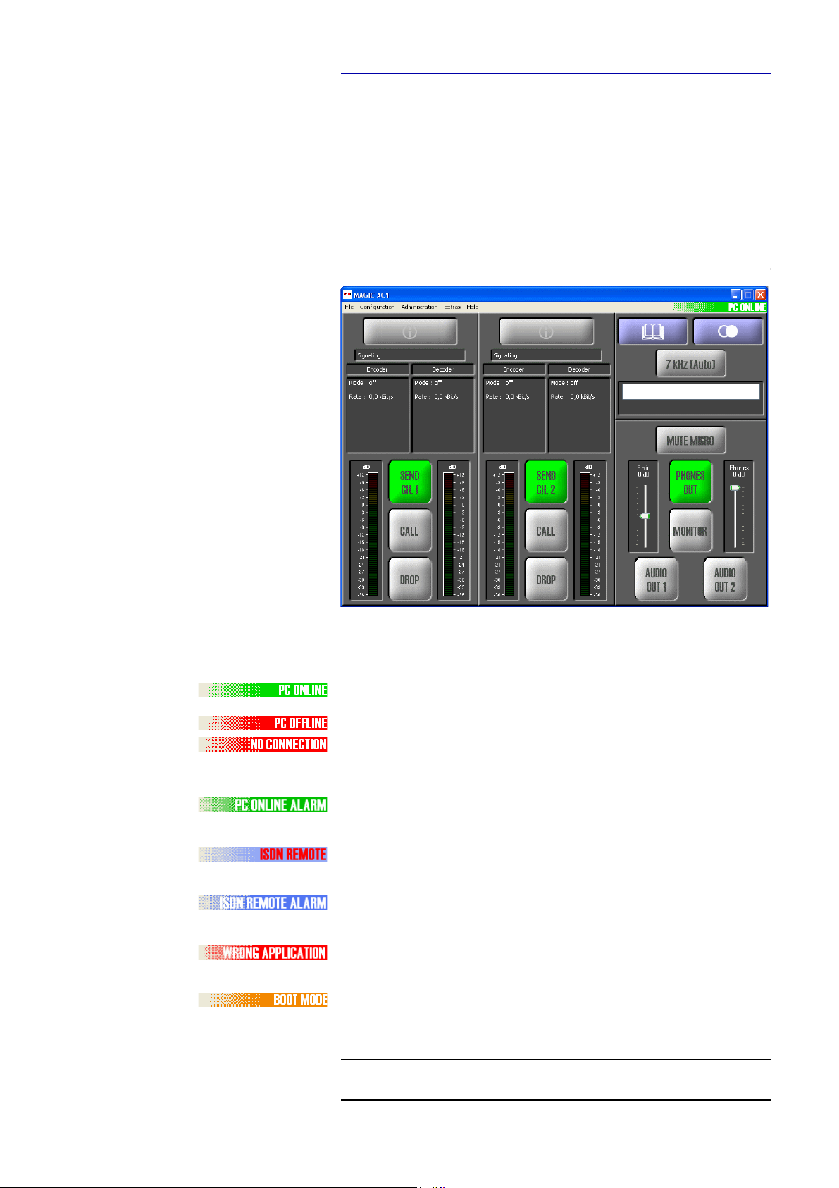
After starting the MAGIC DC7/AC1 Software, the main window (ISDN
mode) is automatically displayed.
FIG. 8 MAIN WINDOW IN THE ISDN MODET
The connection status between PC and the system is displayed in the upper
right corner of the window:
PC ONLINE: connection to the PC is ok
PC OFFLINE or NO CONNECTION:
connection to the PC is faulty
The following status messages are also possible:
PC ONLINE ALARM: an alarm has occurred
(see System Monitor for alarm message, blinking green-dark green)
ISDN REMOTE: A remote connection is established
(blinking red-white)
ISDN REMOTE ALARM: an alarm has occurred in the
remote system (blinking blue-dark blue)
WRONG APPLICATION: you are using the
software with the wrong unit (e.g. MAGIC TH2)
BOOT MODE: no valid firmware on
the system (orange). Please download the latest software (see
CHAPTER 5.8.6).
TIP
If you click on the status message, the System Monitor is displayed which
shows the system status in detail (see CHAPTER 5.9.1).
PAGE 35
Page 36
Windows PC Software
NOTE
If the connection is faulty, please check the following points:
– External power supply of the system is plugged in (display available)
– Serial 1:1 connecting cable is connected to the PC and the system
– Correct COM Port and baud rate are selected in the software
(Configuration
5.5.2 Connection status
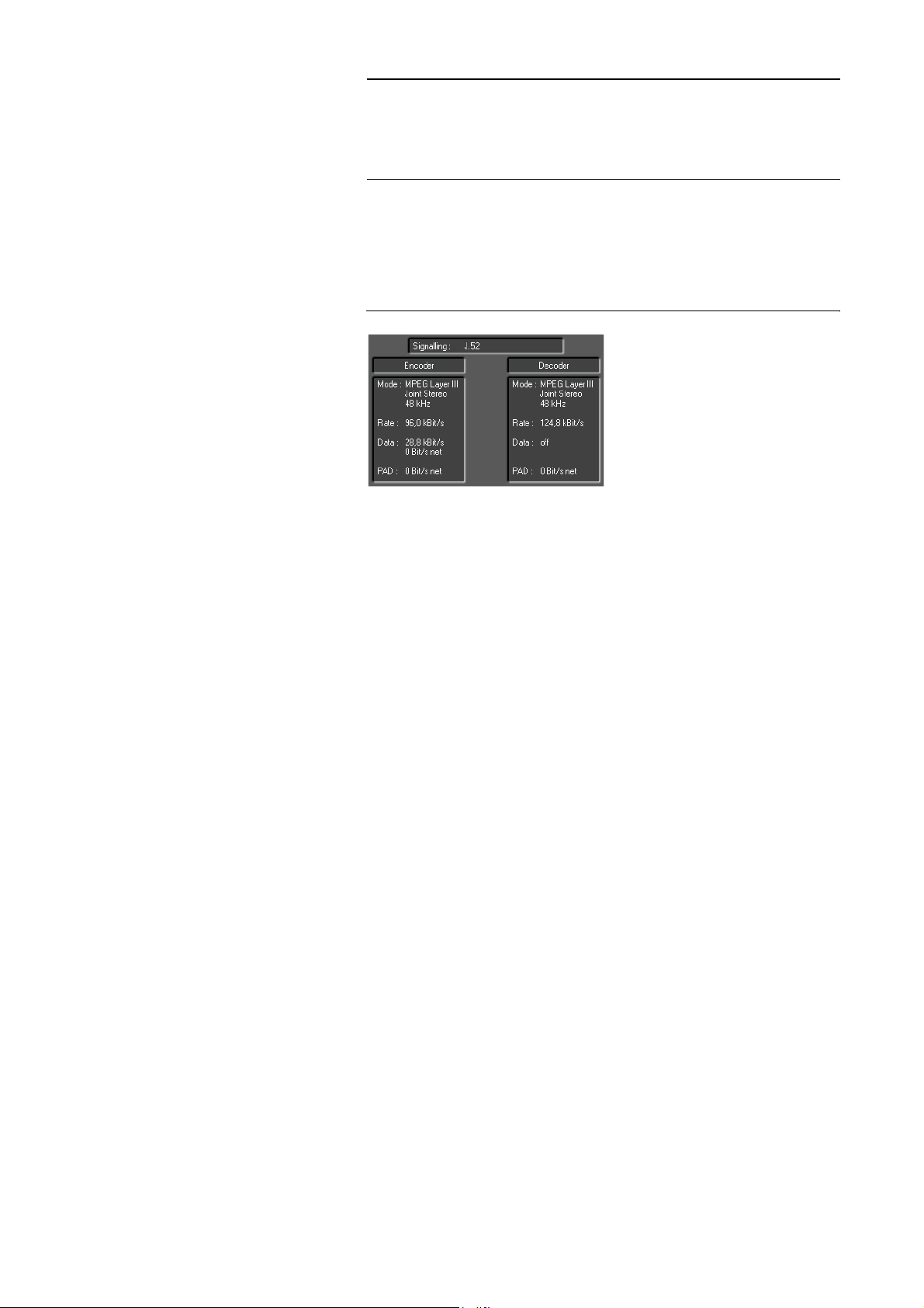
Via the connection status, you get detailed information about the current
transmission separately for transmit and receive direction.
FIG. 9 DISPLAY OF CONNECTION STATUS
Displayed are:
→
COM Port, see Page 51)
– the signalling mode (Signalling)
• Telephone
• SRT (Statistical Recovered Timing)
• MPEG 64 kBit/s unframed
•J.52
•MusicTaxi
•CCS-L2
• Fixed Multiplex
–the operating mode (Mode)
• Coding algorithm (G.711, G.722, ISO/MPEG Layer II/III)
• Coding mode (Mono, Dual Channel, Stereo, Joint Stereo)
• Sampling frequency (16 kHz, 24 kHz, 32 kHz, 48 kHz)
–the bit rate (Rate) for the Audio transmission
–the data (Data) for J.52 transmissions
• Gross data rate
• Net data rate
–the PAD data rate (Program Associated Data) in the MPEG data stream
PAGE 36
• Net data rate
Page 37
5.5.3 Operating elements
Info button
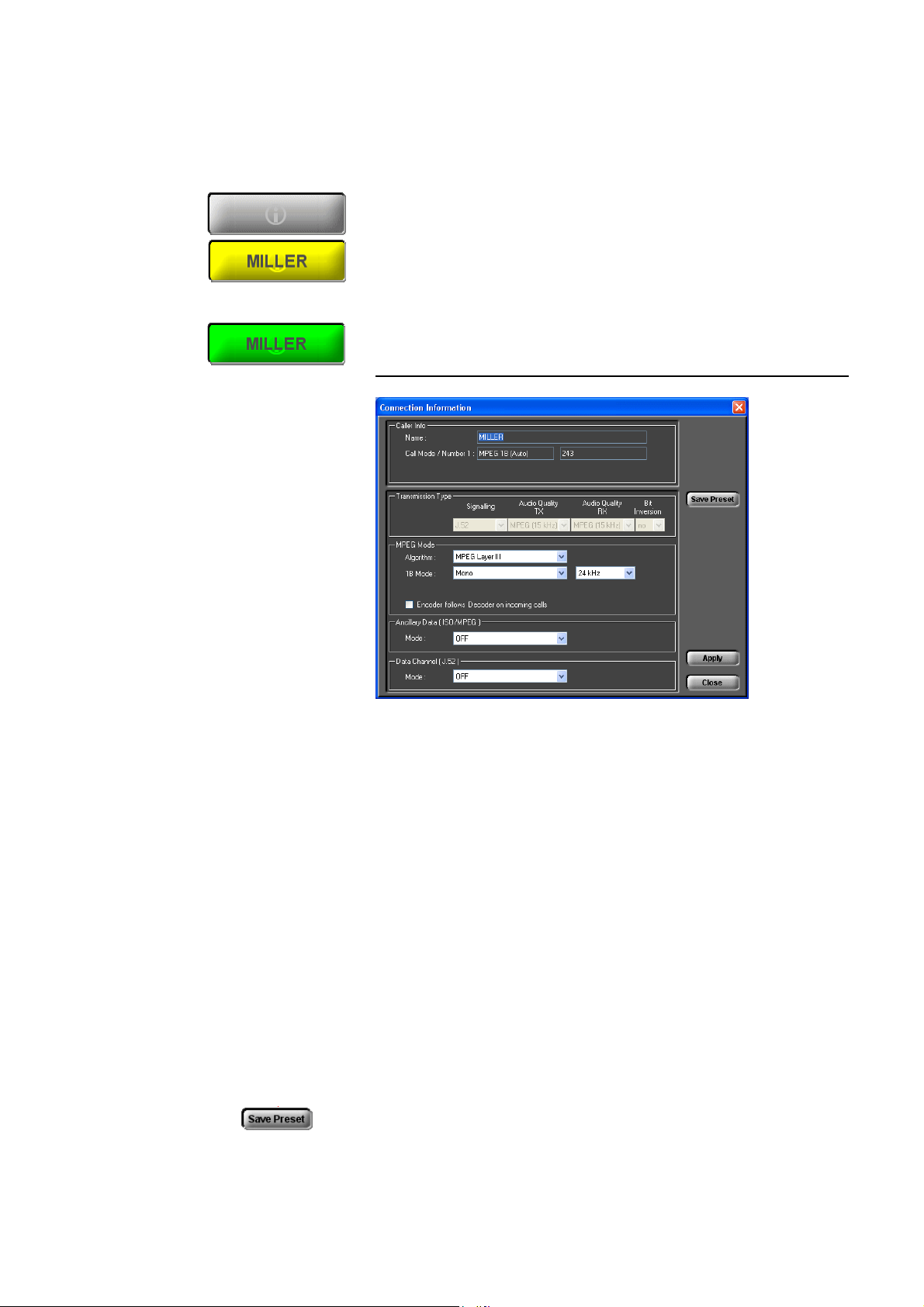
The Info button is either displayed in grey, yellow or green:
• grey: No connection
• yellow: Incoming or outgoing call. If a telephone book entry exists for the
caller, the corresponding name is displayed. If you click on the Info button,
the Connection Information window is displayed.
• green: Existing connection. If you click on the Info button, the Connec-
tion Information window is displayed.
FIG. 10 CONNECTION INFORMATION
Windows PC Software
•Under Caller Info the telephone book entry - if available - is displayed.
Otherwise you see only the calling number, if it is transmitted.
• The type of the current transmission is displayed under Transmission
Type (further details you will find from Page 69 onwards). Parameters
which cannot be changed for this transmission are displayed in light grey.
• If the transmission is an ISO/MPEG connection, the Audio parameters are
additionally displayed under MPEG Mode. These parameters can also be
changed during a connection. You can select the ISO/MPEG algorithm
(Algorithm) Layer III and optionally Layer II, the coding mode and the
sampling frequency. Additionally, you can select if the encoder should
work with the same parameters as the decoder. In this case, please enable
the option Encoder follows Decoder on incoming calls.
• ISO/MPEG connections and/or J.52 connections allow additionally the
transmission of transparent data channels in parallel, which can be configured under Ancillary Data (ISO/MPEG) respectively Data Channel (J.52)
(for further details please see Page 66 onwards).
• You can save changes as new transmission modes. Please press the button
Save Preset. The new mode can be found under Configuration
GIC DC7/AC1
→
Transmission → User Defined, where you can also
→
MA-
PAGE 37
Page 38
Windows PC Software
no Audio source
selected
at least one
Audio source selected
check or change the settings. When you want to establish a connection,
you can select the new transmission mode directly from the front keypad
of the system or in the PC Software.
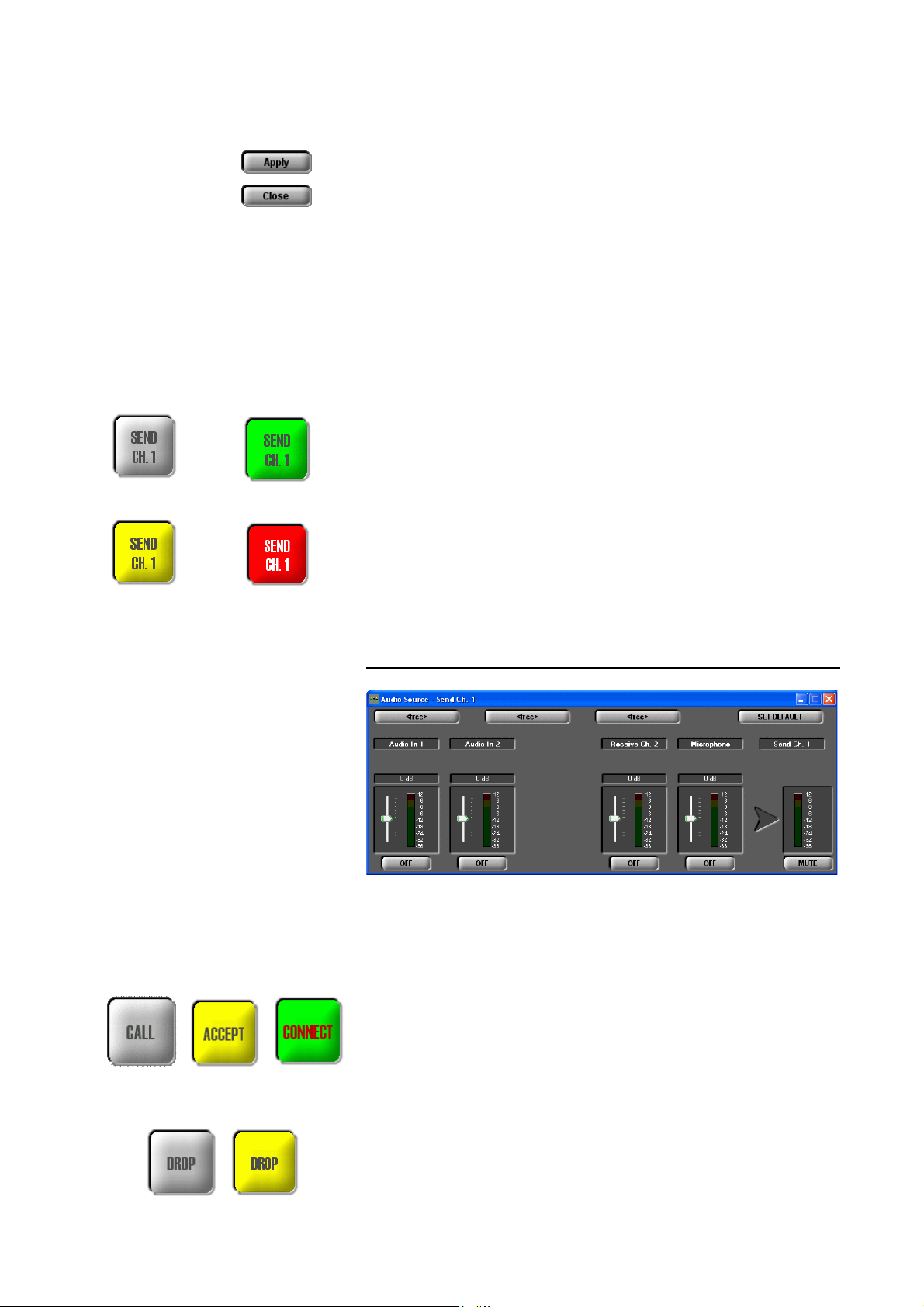
• Changes are applied by pressing the Apply button.
• The window is closed by Close.
Selection of the Audio sources for the transmit direction
By pressing the button SEND CH.1 respectively SEND CH.2 the window, in
which the Audio sources (Audio Source) for the transmit direction can be
selected, is displayed.
Depending on the configuration of the Audio mixer, the SEND CH. button
can have the following colours:
grey: No Audio source is selected for the transmit direction, i.e. the remote
side would hear nothing.
green: At least one Audio source is activated
blinking in red: The Mute function is enabled for the selected channel, i.e. the
remote side would hear nothing.
Auto-Ducking
activated activated
Mute
yellow: The Auto-Ducking function is enabled (see page 77).
Depending on the transmission procedure, the available levels are displayed.
Details for the configuration of the Audio mixer can be found under
CHAPTER 5.5.3.1.
FIG. 11 AUDIO MIXER TRANSMIT DIRECTION
CALL/ACCEPT/CONNECT button
grey: With the CALL button, the connection can be established after the calling number has been entered and the mode has been selected.
PAGE 38
blinking in yellow: An incoming call can be accepted with the ACCEPT button if the auto answer is disabled.
green: Connection is established. If you click on the CONNECT button and
the Security Option is enabled, a control panel is displayed.
DROP button
grey: With the DROP button you can disconnect a connection.
Page 39
Windows PC Software
blinking in yellow: Incoming or outgoing call can be rejected or stopped.
Telephone book
By clicking on the Telephone book button, the phone book is opened. Details
can be found in CHAPTER 5.6.1 from Page 45.
Redialling
Via the Redialling function, the 10 most recently dialled calling numbers are
available. After pressing the key, a context menu is displayed with all existing
entries. Together with the calling number, theTransmission Mode which
was used is also saved. If you want to call a displayed number with a different
transmission mode, you must re-enter the calling number and the desired
transmission mode.
With Cancel you can close the context menu without making a call.
Transmission mode
NOTE
WithTransmission mode you select the desired transmission parameters for
your connection, which you can set under Transmission Modes in the software (see CHAPTER 5.7.2.2.1, page 64)
In the delivery status the following modes are displayed:
– Telephone
–7 kHz (Auto)
– MPEG 1B (Auto)
– MPEG 2B (Auto)
If you configured your own transmission modes (see User Defined Transmission Modes, CHAPTER 5.7.2.2.2, Page 68), these modes are also dis-
played if you click on the transmission mode button.
With Cancel you can close the context menu without changing the transmission mode.
Further details about the transmission modes can be found in the chapter
„The Auto Dynamic Sync Procedure“ from Page 137.
When a connection is dropped, the system is automatically reset to the default
transmission mode, if you have set a default transmission mode under Con-
figuration
dio Mode
lected mode is activated.
→
MAGIC DC7/AC1 → Transmission Modes → Default Au-
→
Mode. If you have selected the option Off, the most recently se-
TIP
You should select one of the Auto Modes as default transmission mode, since
only in this way you can be sure that the automatic synchronisation procedure (ADS) is used when there is an incoming call.
PAGE 39
Page 40
Windows PC Software
Manual Dialling
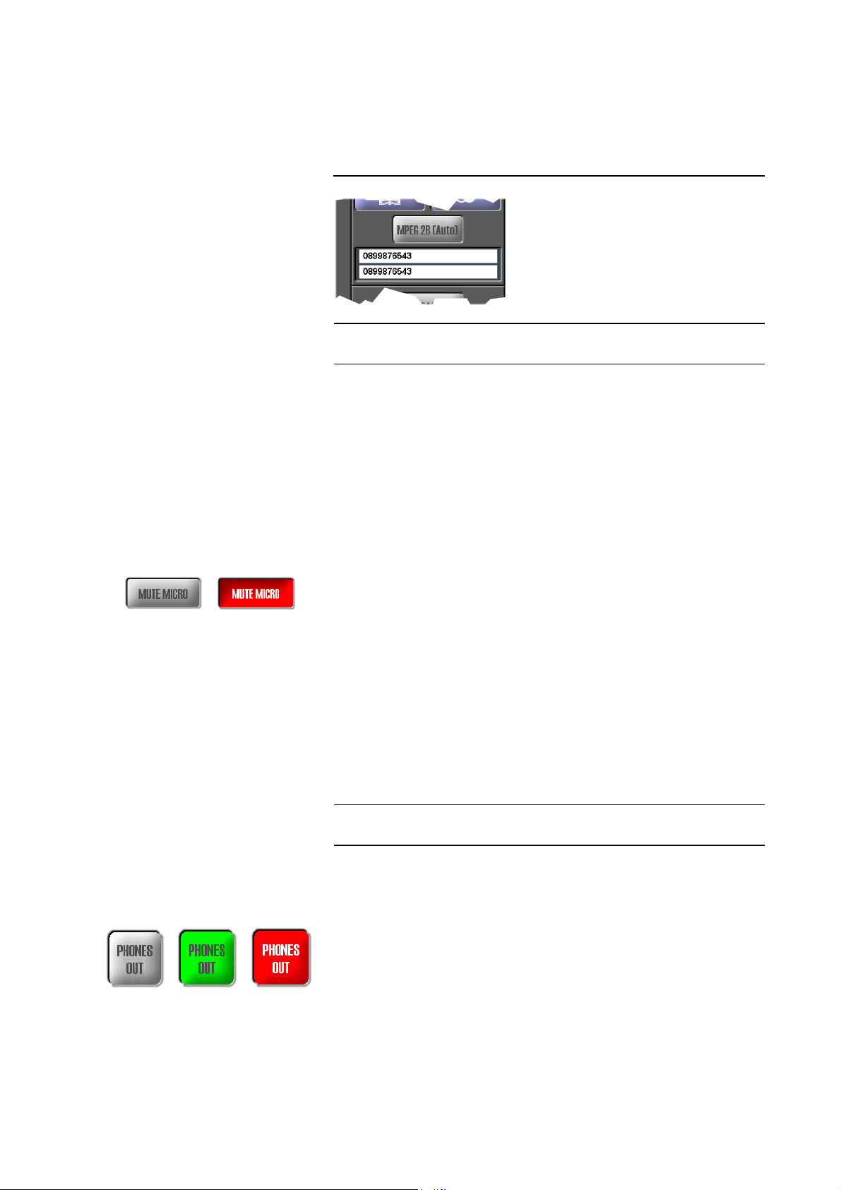
Via the entry field for the calling number, you can dial manually instead of using the telephone book. Depending on the operating mode, one or two fields
are available.
FIG. 12 MANUAL DIALLING
TIP
You can copy a phone number with <CTRL>+<c> and paste it with
<CTRL>+<v>.
For the entry field, all numeric characters ’0’...’9’ as well as the characters ’*’
and ’#’ are allowed. The length of the calling number must not be more than
20 characters.
With a ’-’ placed in front of the calling number (e.g. „-123“) you can temporarily suppress the prefix number for getting an outside line (see also Page 55,
Prefix Number).
Mute microphone
By clicking on the MUTE MICRO button, the microphone connected to the
headset interface is muted.
grey: Mute function is not active
blinking in red: Mute function is active. Additionally, in the Audio mixer
MUTED is displayed at the microphone level.
Headphones output (Phones Out)
PAGE 40
NOTE
Via the button PHONES OUT you select the Audio signals which you want to
hear at the headphones if connected.
If the fee-based option Mixer Tool Plug-In (Order number 430201), you can
select only one signal from all sources.
Depending on the configuration of the Audio mixer, the PHONES OUT button can be displayed in the following colours:
grey: No Audio source activated. In this case, nothing could be heard at the
headphones output.
green: At least one Audio source is activated
blinking in red: The Mute function is enabled. In this case, nothing could be
heard at the headphones output.
Please consider also the further configuration possibilities of the headphones
interface from Page 76, which allow an allocation of the left and right channel.
Page 41
Windows PC Software
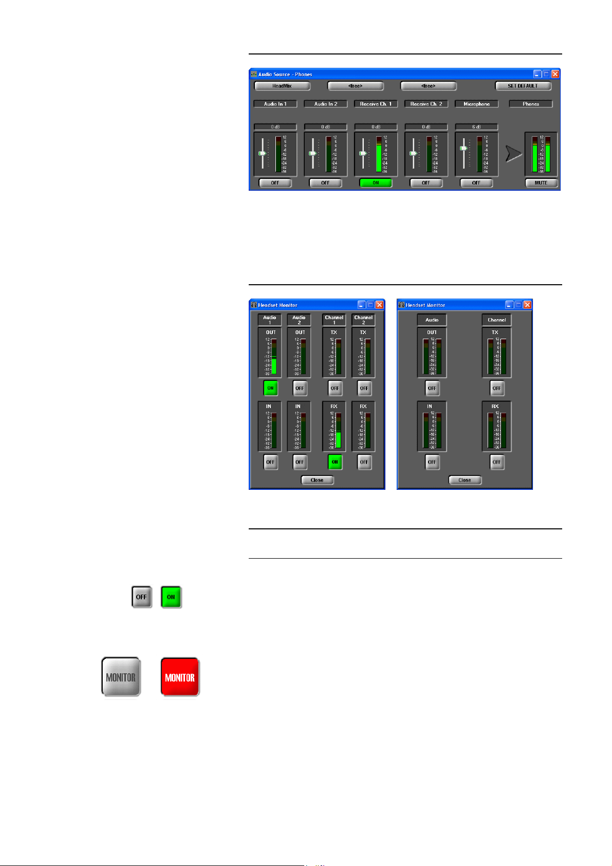
FIG. 13 AUDIO MIXER HEADPHONES OUTPUT
Monitor
By pressing the MONITOR button the window Headset Monitor is opened
with which you can monitor all Audio inputs and outputs.
FIG. 14 HEADSET MONITOR
NOTE
Display with two
independent mono channels
Display during a
stereo transmission
If the fee-based option Mixer Tool Plug-In (Order number 430201) is not enabled for your system, you can only monitor one signal at a time.
Depending on the selected transmission mode, the display is adjusted (see
Fig. 14). With the ON/OFF button, you can activate/deactivate monitoring
for a signal.
With Close you can close the window.
When the Headset Monitor window is opened, the MONITOR button is displayed in red to indicate that currently you are not listening to the Audio signals which you have selected for the headphones under PHONES OUT (see
page 40). If the window is closed, the button is displayed in grey.
PAGE 41
Page 42
Windows PC Software
Transmit-receive level ratio for the headphones
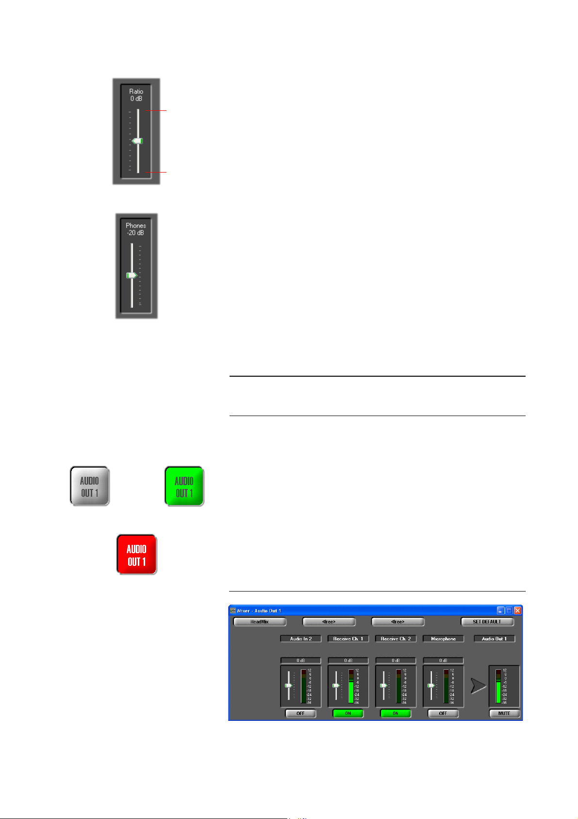
Via the Ratio level meter you can set the level ratio for the headphones output between the transmitted and the received Audio signal.
max. TX
max. RX
NOTE
The ratio can be adjusted within the range of 0...+16 dB. If you select TX+16
dB your transmitted signal is amplified to the maximum and if you select
RX+16 dB the received signal is amplified to the maximum.
Especially for live reporting, in this way you can adjust the levels as you like.
Headphones volume
With the Phones level meters, the volume of the headphones is selected.
The level can be adjusted within the range of 0...-40 dB.
Selection of the Audio sources for the Audio output
By pressing the AUDIO OUT 1 respectively AUDIO OUT 2 button the window
for the selection of the Audio Source for the Audio output is opened.
If the fee-based option Mixer Tool Plug-In (Order number 430201) is not enabled for your system, you can only select one Audio source for the Audio
output.
no Audio source
selected
Mute function
activated
at least one Audio
source selected
Depending on the configuration of the Audio mixer, the AUDIO OUT button
can be displayed in the following colours:
grey: No Audio source activated. In this case, nothing can be heard.
green: At least one Audio source is activated
blinking in red: The Mute function is activated for the selected channel. In
this case, nothing can be heard on the remote side.
Depending on the transmission procedure, the available level meters are displayed. Details about the configuration of the Audio mixer can be found in
CHAPTER 5.5.3.1.
FIG. 15 AUDIO MIXER AUDIO OUTPUT
PAGE 42
Page 43
Windows PC Software
5.5.3.1 Audio mixer to select sources and output equipment
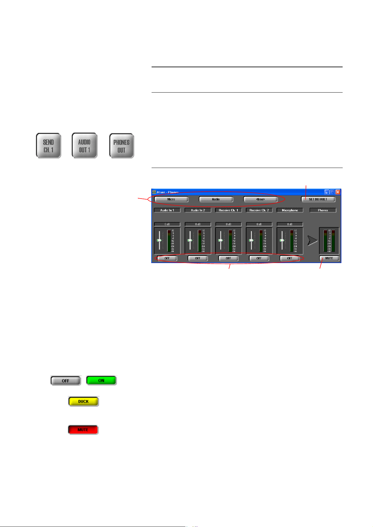
MAGIC DC7/AC1 provides and integrated Audio mixer which allows you to
configure Audio sources and output devices according to your requirements.
.
NOTE
Mixer Presets
If the fee-based software option Mixer Tool Plug-In (order number 430201) is
not enabled, you can always select only one signal for an output device at a
time.
The Audio mixer can be configured via the overview matrix which opens via
Extras
→
Audio Mixer (see CHAPTER 5.9.2, page 103) or via the respective
Audio output device:
• SEND CHANNEL 1/2
• AUDIO OUT 1/2
• PHONES OUT
FIG. 16 AUDIO MIXER
Standard
Mixer Preset
Mute AudioActivate/deactivate Audio source
output device
Depending on the selected transmission mode, the following Audio sources
are available:
• Audio In 1/2
• Receive Channel 1/2
•Microphone
Each of these Audio sources has a digital level setting which allows an increasing or decreasing of the level of 16 dB.
With the button ON/OFF you can activate or deactivate each Audio source
for the Audio output device.
For the Audio output device SEND CHANNEL 1/2, it is possible to activate
the Auto-Ducking functionality for the Audio source Audio In 1/2 if the Mixer
Tool Plug-In option is enabled.
Each Audio output device can be switched off by pressing the MUTE button.
PAGE 43
Page 44
Windows PC Software
Mixer Presets
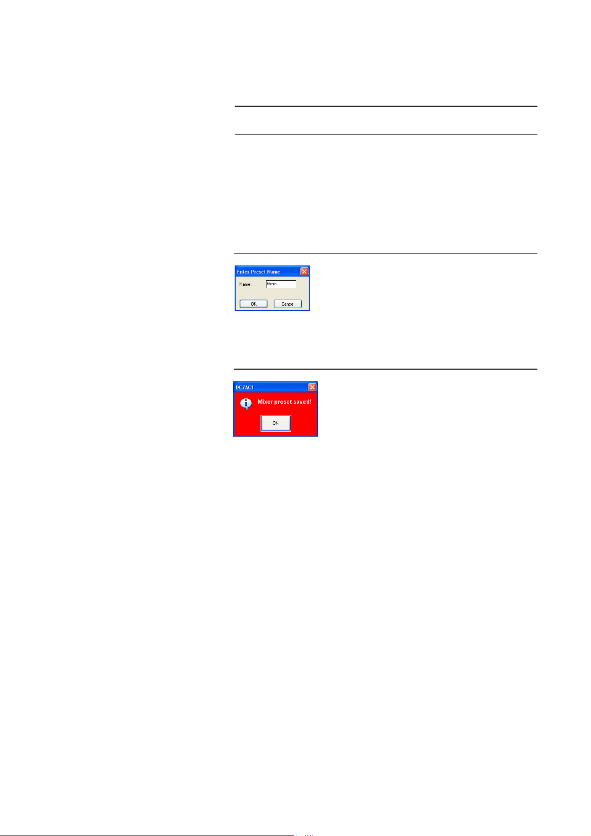
In the system, up to three Mixer Presets can be saved and reloaded by a keypress.
NOTE
The Mixer Presets apply to all Audio sources and output devices, even if they
are not displayed.
Please follow the instructions below:
– Adjust the Audio mixer for all Audio sources and output devices accord-
ing to your requirements.
–Press one of the Mixer Preset buttons for about two seconds. The dialogue
for the entry of a Preset Name is displayed. the length of the names must
not exceed 8 characters.
FIG. 17 ENTRY OF A PRESET NAME
–After the OK button is pressed, a confirmation is displayed that the Mixer
Preset has been saved successfully.
FIG. 18 MIXER PRESET SAVED
– To reload a mixer configuration, please click on the Mixer Preset button
for a second.
– To reset the system to the default settings, please click on the SET DE-
FAULT button. The mixer is configured in the following way:
• all levels to 0 dB
→
• Receive Channel 1
• Receive Channel 2
•Audio In 1
•Audio In 2
That means, the received signal is available at the Audio output and the
signal from the Audio input is transmitted to the remote side.
→
→
Send Channel 2
Audio Out 1
→
Audio Out 2
Send Channel 1
PAGE 44
Page 45
5.5.3.2 Telephone book
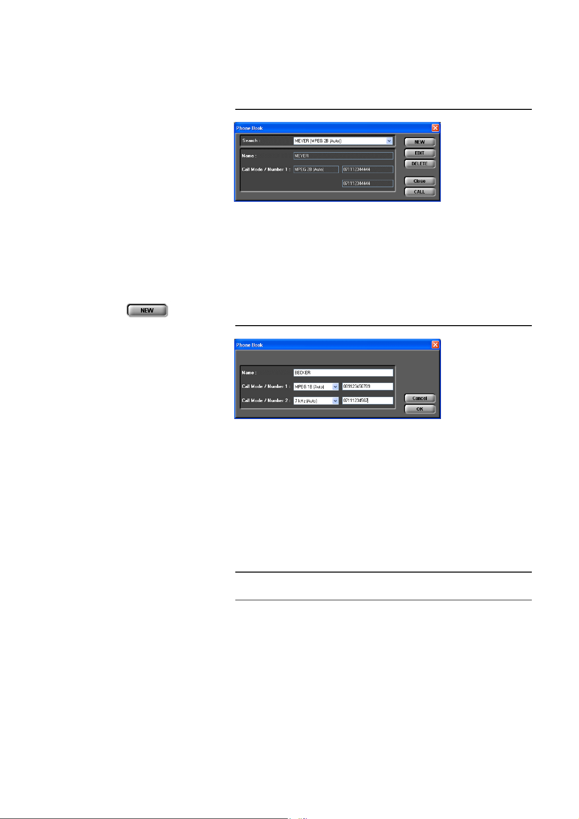
By pressing the telephone book button, the telephone book dialogue is
opened.
FIG. 19 TELEPHONE BOOK DIALOGUE
You can search an already existing entry via the die DropDown list Search or
you simply enter the first character of the name for which you want to search.
A search by calling numbers is not possible.
In the detailed view below, the Name, the Call Mode (transmission mode)
and the calling numbers (Number 1/2) are displayed.
A new entry can be created with NEW.
Windows PC Software
TIP
FIG. 20 NEW TELEPHONE BOOK ENTRY
Please enter the Name of the caller you want to add to the telephone book.
The length of the name is limited to 20 characters.
Under Call Mode/Number 1 you need to select the transmission mode, which
is to be used when the entry is called and then enter the calling number.
If you select a 1 B transmission mode you can configure a second completely
independent connection for the second channel (Call Mode/Number 2). However, as transmission mode you can only select Telephone or 7 kHz (Auto).
In this way, you have the possibility to call two participants at the same time
via one telephone book entry.
You can copy a calling number with <CTRL>+<c> and paste it with
<CTRL>+<v>.
For the entry field, all numeric characters ’0’...’9’ as well as the characters ’
and ’#’ are allowed. The length of the calling number must not exceed 20 cha-
racters.
With a ’-’ placed in front of the calling number (e.g. „-123“) you can suppress
the prefix number for getting an outside line temporarily (see also Page 55,
Prefix Number).
PAGE 45
’
*
Page 46
Windows PC Software
With OK, the entry is saved, with Cancel you can cancel the entry at any time.
NOTE
Please notice that the telephone book entries are stored in the system and not
on the PC. Via the menu File
→
Phone Book → Import/Export you can also
load a telephone book from your PC or save a phone book on your PC.
An already existing entry can be edited with the button EDIT.
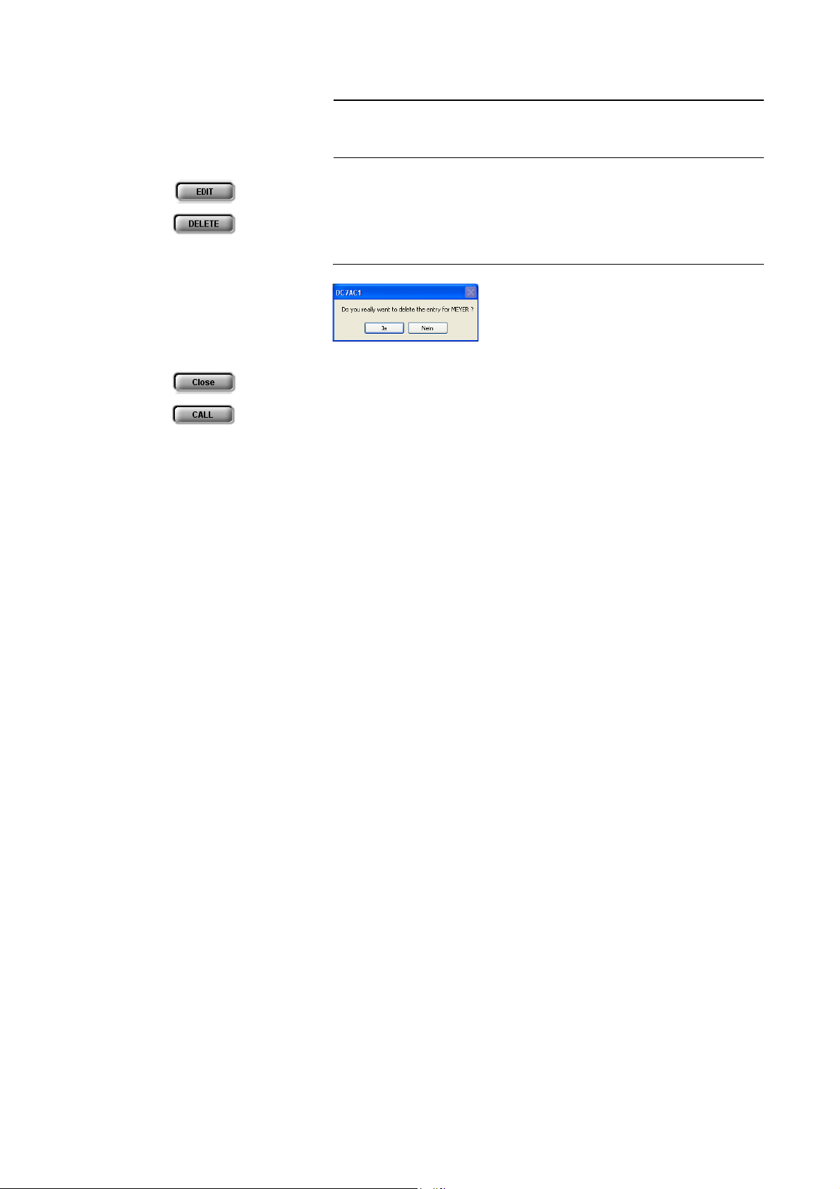
To delete a telephone book entry, please press the DELETE button. To avoid
that entries are deleted by accident, you have to confirm your selection.
FIG. 21 CONFIRMATION TO DELETE AN ENTRY
With Close you can close the dialogue without any further action.
To establish a connection with a telephone book entry directly, please press
CALL.
PAGE 46
Page 47
5.6 Menu File
Under the Menu File you can find all functions for the export/import of system files.
5.6.1 Submenu Phone Book
Windows PC Software
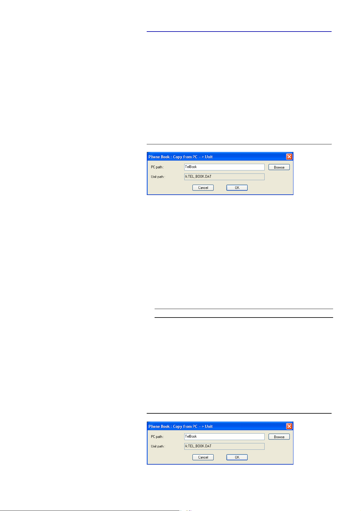
To import a telephone book from the PC, please select File
→
Import.
→
Phone Book
With Browse you can search for the telephone book which you want to import. The file extension for a telephone book is ‘.csv‘. Such a file can be edited
with e.g. MS
FIG. 22 IMPORTING A TELEPHONE BOOK
®
EXCEL.
File format (Example):
DC7AC1;3;2
Name;Call Mode 1;Call Mode 2;Config File;Number 1;Number 2
JERRY LEE;8;0;;160;
ULRIKE LAUTERBACH;2;0;;141;
AVT SUPPORT;0;0;MUSICTAX;123456;
DIANA EL-TATTAN;1;0;;123;
WOLFGANG PETERS;0;0;DEMO;130;131
;Presets
1;MUSICTAX;17;0201031F016800670069006C007A82980C
1;DEMO;17;0201031F016800670069006C007A829108
Attention: The first two lines form the header and must not be missing.The
lines „Presets“ are only available, if you work with Transmission Modes.
Possible values for Call Mode 1/2:
Value
Call Mode 1 Call Mode 2
configuration file used no connection
0
Telephone Telephone
1
7 kHz 7 kHz
2
MPEG 1B -
8
MPEG 2B -
9
To export a telephone book, please go to File → Phone Book → Export. The
file is saved with the extension ‘.csv‘. The desired directory path can be selected via Browse.
FIG. 23 EXPORTING A TELEPHONE BOOK
PAGE 47
Page 48

Windows PC Software
5.6.2 Submenu Operation Settings Presets
5.6.3 Submenu User Transmission Modes
Via Import, a Preset can be imported from a data carrier (disk, USB stick,
etc.). The file extension of the configuration file is always ‘.pst‘. After clicking
on the button, the file browser is opened, via which the desired file can be selected.
With Export All you save all already existing presets in a directory of your
choice. For each preset, a file with the extension ‘.pst‘ is generated.
The functions are identical with the Import and Export All functions under
Configuration
The option Import allows you to import a User Transmission Modes from
a data carrier (disk, USB stick, etc.). The file extension of the file is always
‘.tmm‘. After clicking on the button, the file browser is opened, via which the
desired file can be selected.
With Export All you save all already existing User Transmission Modes in
a directory of your choice. For each mode, a file with the extension ‘.tmm‘ is
generated.
→
Presets → Manage Presets (see CHAPTER 5.7.3.2).
5.6.4 Submenu System Settings
NOTE
With the selection File
complete system configuration from a data carrier. The file extension of the
system configuration file is always ‘.tcg‘.
The following settings are imported:
– Basic Settings (see CHAPTER 5.7.2.3)
–All Operation Settings (see CHAPTER 5.7.2.1)
– All user-defined Transmission Modes (see CHAPTER 5.7.2.2.2)
–All Mixer Presets (see CHAPTER )
Correspondingly, via File
tem configuration can be saved. The storage location and position can be chosen by yourself.
Please note that the telephone book is not saved with the system configuration.
→
System Settings → Import, you can import a
→
System Settings → Export, the complete sys-
PAGE 48
Page 49

5.6.5 System Log File
With the selection File
ISDN Log File of the MAGIC DC7/AC1 system. The file is saved with the extension ‘.log‘. The desired directory path can be selected with Browse.
FIG. 24 EXPORTING THE ISDN LOG FILEI
Windows PC Software
→
System Log File → Export you save the internal
NOTE
A log file is only generated in the system, if the function System Logfile
(CHAPTER 5.9.1, Page 102) has been activated in the System Monitor.
The log file can be opened and analysed with the optional ISDN S0 Monitor
(see CHAPTER 8.2, page 120).
PAGE 49
Page 50

Windows PC Software
5.6.6 Submenu Exit
Via the submenu Exit you can close the MAGIC DC7/AC1 PC software.
PAGE 50
Page 51
5.7 Menu Configuration
5.7.1 Submenu COM Port
The system is connected with a PC or the MAGIC DC7/AC1 Keypad via the
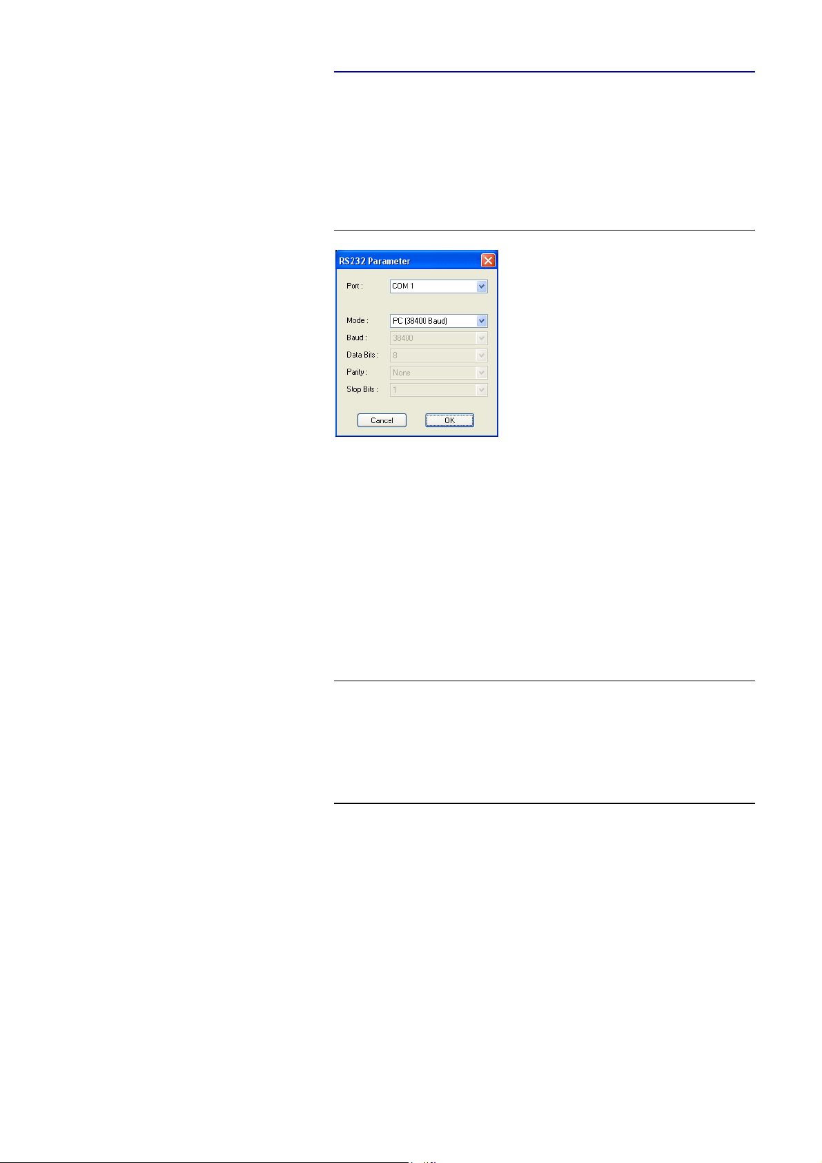
serial RS232 interface and a 1:1 connecting cable. The settings of the COM Port
at the PC can be edited under Configuration
FIG. 25 RS232 PARAMETER OF THE COM PORT
Windows PC Software
→
COM Port.
NOTE
Please select the interface of the PC, which is connected with the MAGIC
DC7/AC1, as Port.
Under Mode you can configure the desired mode:
– PC & Keypad (9600 Baud): to connect the Keypad or a PC
– PC (19200 Baud): to connect a PC
– PC (38400 Baud): to connect a PC
– PC (57600 Baud): to connect a PC
– PC (115200 Baud): to connect a PC
The MAGIC DC7/AC1 Keypad only supports the baud rate 9600 Baud. Therefore, please select always the setting PC & Keypad (9600 Baud) if you use
the Keypad. Of course, this baud rate can also be used if a PC is connected.
If the PC is used via the RS232 interface, the selected baud rate must match
with the baud rate of the COM port (see also configuration of the RS232 Interface, Page 73).
All further parameters such as Data Bits, Parity and Stop Bits cannot be configured.
PAGE 51
Page 52
Windows PC Software
5.7.2 Submenu MAGIC DC/AC1
Via the submenu MAGIC DC7/AC1, the system can be configured completely.
After the configuration has been changed, the following options are available:
•With OK the configuration dialogue is closed and all settings are saved
and applied to the system.
• The function Apply Now allows you to save the current settings without
closing the configuration dialogue.
• Cancel cancels all settings made.
In the configuration, it is differentiated between Basic Settings, which usu-
ally do not have to be changed during the operation and the actual Operation
Settings. The Operations Settings also include the Transmission Modes. Basic Settings can not be saved as Preset (see CHAPTER 5.7.3) - whereas Operation Setting can be saved as Preset.
For clarification:
A Preset includes all settings made under Operation Settings and Trans-
mission Modes. Various Presets can be saved in the system and loaded by
the user.
5.7.2.1 Operation Settings
All settings made under Operation Settings can be saved as Preset.
5.7.2.1.1 Line Interface
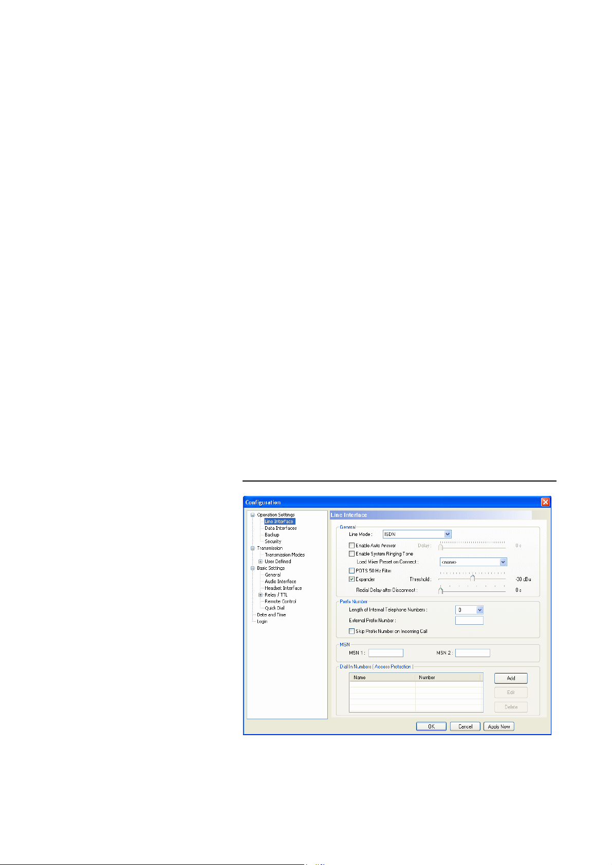
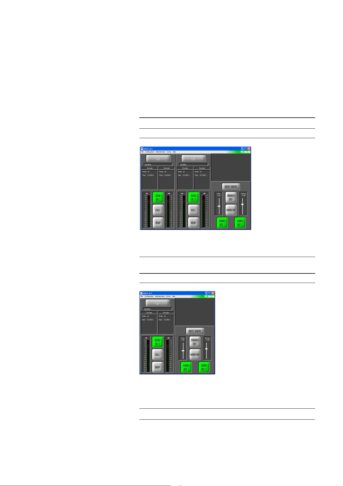
The menu item Line Interface allows a configuration of the ISDN respectively the POTS line interface.
FIG. 26 LINE INTERFACE
PAGE 52
Page 53
Windows PC Software
General
•Under Line Mode you select the line interface which you want to use. The
following options are possible:
– ISDN: the system is connected to the ISDN network and two independ-
ent channels are available.
– ISDN leased line: the system is connected to the ISDN network and
two independent channels are available. In contrast to the dial-up
ISDN mode, in the ISDN leased line mode, no dialling information is
transmitted. As soon as you connect the system to an ISDN leased line,
a connection is established.
NOTE
NOTE
Please notice that no calling numbers can be entered in this mode.
FIG. 27 MAIN WINDOW IN THE LEASED LINE MODE
– ISDN leased line (B1/2 only): Same functionality as above, except that
only B channel 1 (B1) or B channel 2 (B2) is analysed.
Please notice that only one channel is displayed in the main window. Additionally, no calling number can be entered in this mode.
FIG. 28 MAIN WINDOW IN THE LEASED LINE B1/B2 MODE
NOTE
– POTS: the system is connected to a POTS telephone line. In this oper-
ating mode, only one channel is available. Therefore, an Audio transmission is only possible with a 3.1 kHz bandwidth (G.711).
Please notice that only one channel is displayed in the main window.
PAGE 53
Page 54

Windows PC Software
FIG. 29 MAIN WINDOW IN THE POTS MODE
• With the function Enable Auto Answer you can enable the system to accept the calls automatically.
• If the automatic answer is activated, you can adjust a delay before the call
is accepted by the system. Via the scroll bar Delay you can select a delay
between 0 ... 31 seconds. The default setting is 0 s.
• With the function Enable System Ringing Tone you can switch on the
acoustic call signalling.
• Load Mixer Preset on Connect allows you to load a mixer preset automatically as soon as the connection is established.
If you do not want to use this function, please select the option <none>.
Please also consider the remarks in CHAPTER 5.8.7, Submenu Create 15-
kHz Telephone Mixer Presets.
The following settings are only available in the Line Mode POTS:
• If you activated the POTS 50 Hz Filter, a disturbing 50 Hz humming is filtered out. The disturbing signal is fed into the system via the POTS line.
The reason is mostly a wrong cabling of the PABX.
•An Expander turns down the caller signal automatically, if its level falls
below a certain threshold value. The aim is to completely filter out background noises of callers who are not currently speaking. The Expander is
activated by checking the respective box. With the scroll bar Threshold
you can adjust the threshold for the Expander within the range of -40 ... 20 dBu. The default setting is -30 dBu.
• Via the scroll bar Redial Delay after Disconnect you can adjust the redialling delay after a connection has been dropped since the POTS telephone
line is not immediately ready for redialling. This function is possibly necessary when the dialling function via a TTL contact is used (see CHAPTER
5.7.2.3.4, page 78).
PAGE 54
Page 55

Prefix Number
Windows PC Software
NOTE
TIP
The following settings are only necessary, if the system is operated with a
PABX.
In the ISDN Leased Line Mode, these settings are not available.
•Under Length of Internal Telephone Numbers you indicate the length of
your internal telephone numbers. In this way, the prefix number is dialled
automatically, if the length of the entered calling number exceeds the
Length of Internal Telephone Numbers you indicated here. If you do not
want to use this functionality, or if you use the system with a main connection, please enter a 0 into the respective field.
Examples: Length of internal telephone numbers: 3
Calling number entered: 130
It is dialled: 130
Length of internal calling numbers: 3
Calling number entered: 5271130
It is dialled: 0 5271130
To skip the automatic prefix number temporarily, you can place a „-“ in front
of the calling number (e.g. „-130“)
•Under External Prefix Number you enter the external prefix number
which you must dial to get an outside line. In most cases it is 0.
ATTENTION You must enter the external prefix number at any case if you operate the sys-
tem with a PABX since only in this case the system waits for a dial tone. Without an external prefix number, the calling number is transmitted too fast and
!
NOTE
the connection cannot be established.
• Some PABXs transmit the calling number with prefix number to the system. If you want to transfer the displayed calling number without the prefix number directly into the telephone book, you can enable the function
Skip prefix number on incoming call.
MSN (Multiple Subscriber Number
A MSN can only be entered if the ISDN operating mode has been selected.
Usually the entry of a MSN is not necessary. However, if several systems are
operated with one ISDN interface, you can allocate a certain calling number
to a certain system by entering a MSN.
Example: A telephone, an ISDN PC card and a MAGIC DC7/AC1 system unit
are operated with one ISDN interface. From your provider you got the following MSN: 5271011, 5271012, 5271013.
Without a MSN entry, all three units respond to the incoming call - no matter
which of the three calling numbers was dialled. However, if a different MSN
is allocated to each unit, the system only responds if exactly this MSN was dialled by the caller. If you enter e.g. the MSN ’5271013’ for the MAGIC
DC7/AC1 system, the system will only signal the call, if the caller dialled
’5271013’. However, precondition for this example is that you enter the same
MSN for MSN 1 and MSN 2.
PAGE 55
Page 56
Windows PC Software
Enter the desired MSN under MSN 1 respectively MSN 2. Of course, the same
MSN can be allocated for both B channels. Please notice that a MSN is always
entered without area code.
NOTE
NOTE
Some PABX require the entry of a MSN since otherwise no operation is possible.
If you cannot establish a connection between the MAGIC DC7/AC1 system
and a partner system, but you are sure that the ISDN line is working, you
should try if it works after entering a MSN.
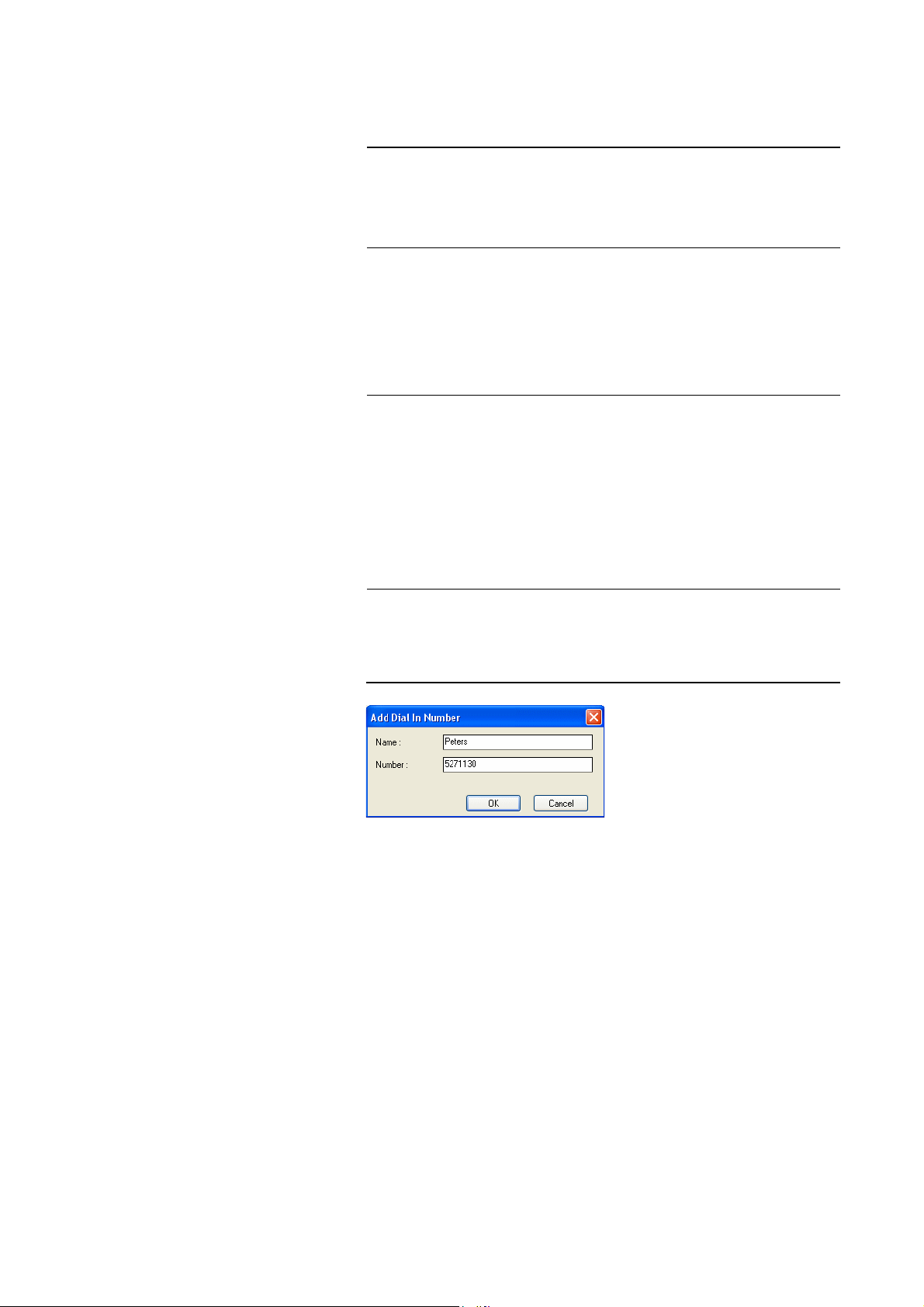
Dial In Numbers (Access Protection)
Via the Dial In Numbers function an access protection for the system can be
activated. All calling numbers which are entered in the list can establish a connection with the system. Please enter Name and Number for each list entry.
Please consider that only numeric characters which are actually entered are
analysed, i.e. if you only enter „130“, all participants with a calling number
which ends with „123“ are allowed to call the system.
The total character length of all entered telephone numbers must not be
higher than 127. With an average length of a telephone number of 12 characters about 10 calling numbers can be saved.
For this functionality the calling number of the participants in the list needs
to be transmitted (CLIP
a
Calling Line Identification Presentation
a
function).
•With Add you can create a new entry.
FIG. 30 ADD A NEW ENTRY
•The button Edit allows to edit already existing entries
•With Delete an entry can be deleted. For safety reasons you must confirm
that you really want to delete the entry.
PAGE 56
Page 57
5.7.2.1.2 Data Interfaces
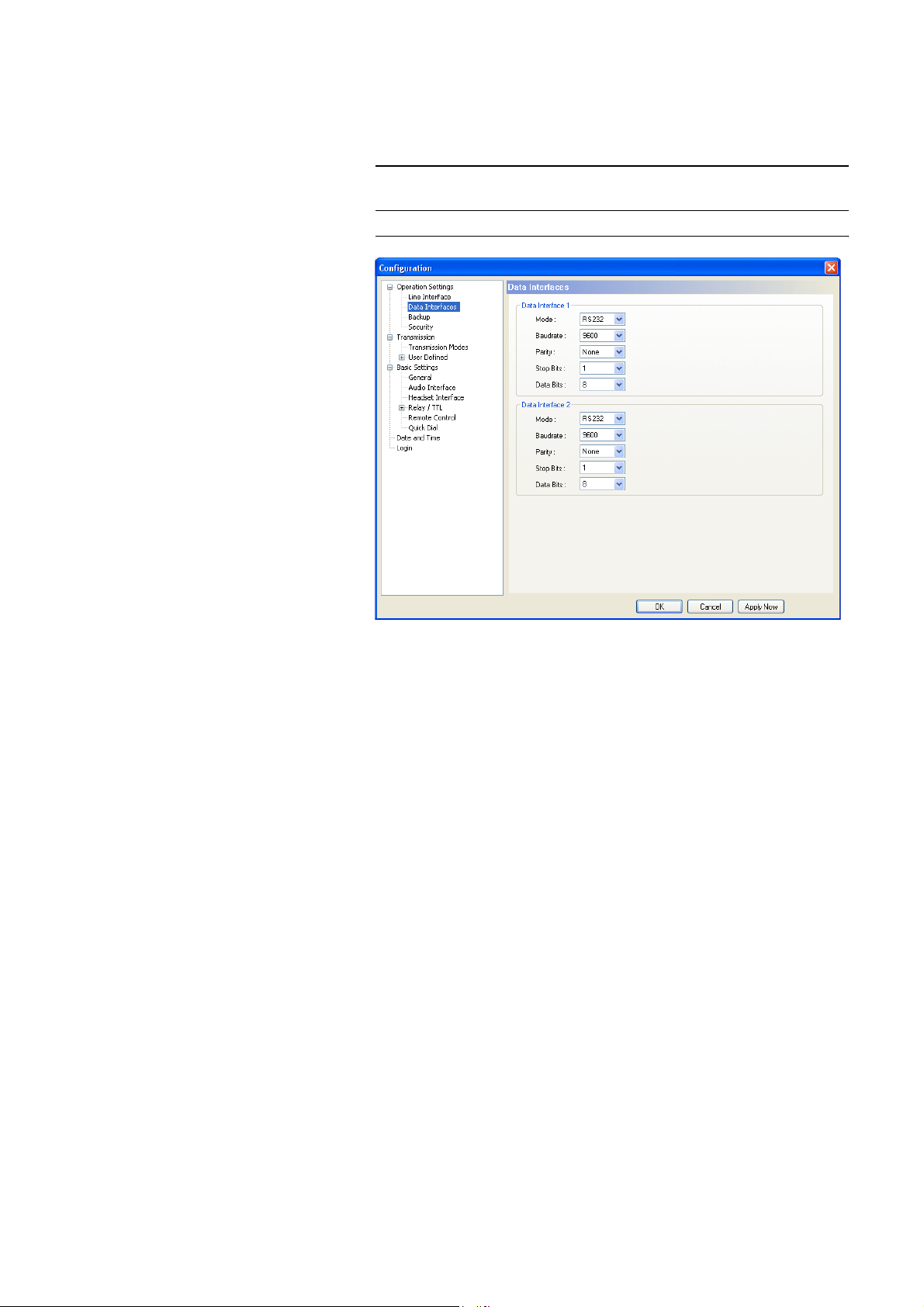
Under Data Interfaces you can configure the two available data interfaces
which allow a transmission of transparent data in parallel to the Audio signal.
Windows PC Software
NOTE
It depends on the selected Audio Transmission Mode (see
CHAPTER Fig. 35) if a data transmission is possible.
FIG. 31 CONFIGURATION OF THE DATA INTERFACE
The configuration options for Data Interface 1 and Data Interface 2 are idetical. The parameters must match with the settings of the corresponding data
source.
•Via the dropdown list Mode you can select the interface type RS232 or
RS485.
The RS232 interface can be used with a maximum cable length of 15m and
is available at many data end devices. The transmission is unsymmetrical,
i.e. only one wire is used for the transmit and one for the receive channel.
The procedure is more interference-prone and limits the maximum cable
length.
In contrast to this, the RS485 interface works with symmetrical transmission (one pair of wires each for transmit and receive direction), whereby
the transmission is less interference-prone and cable lengths of maximum
100m are possible.
• As baud rate the values 300, 1200, 2400, 4800, 9600, 19200 and 38400 can
be adjusted.
•Under Parity you select the desired parity: None, Even or Odd.
• The number of the Stop Bits can be set to 1 or 2.
• The number of the Data Bits can be set to 8 or 9.
PAGE 57
Page 58
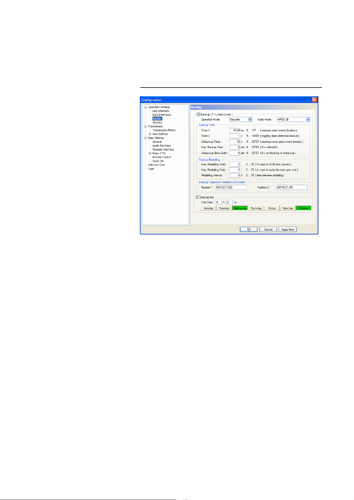
Windows PC Software
5.7.2.1.3 Backup
MAGIC AC1 offers the possibility to use the system as ISDN backup Audio
codec.
Under Backup you find a variety of parameters to adjust the backup functionality to your requirements.
FIG. 32 CONFIGURATION OF BACKUP FUNCTION
• To activate the backup function, please enable the checkbox Backup (TTL
Alarm Event). The backup is triggered by a TTL Pin (e.g. error output of
an external system) (see CHAPTER 5.7.2.3.4, configuration of a TTL-Signal: Backup Alarm Signal).
•Under Operation Mode you decide if the system works as Encoder or De-
coder. In the backup mode, the system works with a fixed multiplexing
scheme without Capability Exchange of the J.52 to guarantee that the connection is established as fast as possible. The backup is always triggered by
the decoder side (e.g. at the transmission site).
With the selection Encoder you simply switch on the fixed multiplexing
scheme. Except the Audio Mode, no further parameters can be configured.
The operating mode should be selected, if the system is installed e.g. in the
studio.
With the selection Decoder all available parameters can be configured.
This operating mode should be selected, if the system is installed e.g. at a
transmission site.
•Under Audio Mode you set the number of the B channels for the backup
connection and the signalling.
– MPEG 1B: Fixed multiplexing scheme according to J.52 with one B
channel. The Audio data rate is 62.4 kbit/s.
PAGE 58
– MPEG 2B: Fixed multiplexing scheme according to J.52 with two B
channels. The Audio data rate is 124.8 kbit/s.
– MPEG 1B Unframed: The transmission is made without J.52 signalling
with ones B channel. The Audio data rate is 64 kbit/s.
Page 59

Windows PC Software
Backup Timer
The timing of the backup can be adjusted with the following timers:
• Timer 1 (Minimum alarm event duration) in milliseconds: Under this setting you can select the minimum duration of a TTL alarm to trigger a
backup. This is to avoid that a backup is established because of very short
disturbances.
The timer can be configured within the range of 0 ... 12700 ms in steps of
100 ms.
• Timer 2 (Toggling alarm detection interval) in seconds: This timer ensures
that a backup is also triggered when the alarm signal is „toggling“. If the
alarm signal is detected for a second time within the selected interval, the
backup connection is established in any case.
The timer can be configured within the range of 0 ... 16383 sec in steps of
1 second.
• Unbackup Timer (Minimum none alarm event duration) in seconds: With
this timer you can configure the maximum time during which no alarm
must occur before the backup connection is released.
The timer can be configured within the range of 0 ... 32767 sec in steps of
1 second.
• Maximum Backup Time in minutes: Via this timer the maximum backup
time can be selected. The backup connection is dropped after this time,
even if the alarm signal still exists.
The timer can be configured within the range of 0 ... 32767 min in steps of
1 minute. if you select the setting 0, the backup time is unlimited.
• Unbackup Block Gate in minutes: If a second backup connection is established within the selected time interval, the backup connection is not dis-
connected automatically anymore. In this case, the backup connection has
to be dropped manually (by pressing the DROP button) or it is dropped
after the maximum backup time the latest. In this way, we want to make
sure that a connection which is sporadically disturbed does not trigger a
backup connection and backup disconnection permanently.
The timer can be configured within the range of 0 ... 32767 min in steps of
1 minute. If you select 0, this function is deactivated and the backup connection is dropped automatically as soon as all criteria are met.
Backup Redialling
Different redialling options are available:
• Maximum Redialling Trials (in case of ISDN error causes): Under this setting, you can adjust how often the decoder tries to redial, if the connection
could not be established because of an ISDN error, such as e.g. „Busy“ or
„No route“, etc.
The number of redialling trials can be adjusted within the range of 0 ... 15.
• Maximum Redialling Trials
(in case of audio decoder synchronisation
lost): Under this setting, you can adjust how often the decoder tries to redial, if the connection can be established but the decoder does not synchronise.
The number of redialling trials can be adjusted within the range of 0 ... 15.
• The pause between two redialling attempts can be configured with the parameter Redialling Interval.
The timer can be adjusted within the range of 0 ... 15 s in 1 second steps.
PAGE 59
Page 60
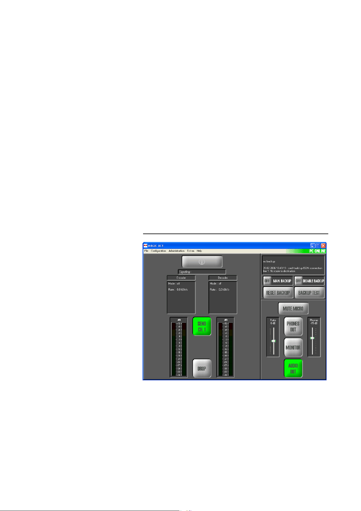
Windows PC Software
5.7.2.1.4 Functions in the main window with activated backup
Backup Telephone Numbers of Encoder
The calling number of the Backup Encoder (e.g. in the studio) you enter under
Number 1 and Number 2 (if MPEG 2B is selected).
Backup Test
To ensure that the ISDN connection and the Audio Codecs work correctly, a
Backup Test can be done. Please activate the relevant option for this.
•Under Test Time you enter the time when the backup test is to be done.
The entry has to be made in the 24h notation (e.g. 19h 25m).
•The weekdays (Monday ... Sunday) on which the test is to be done can be
selected by clicking on the relevant weekday button.
The main window is adjusted according to your configuration if the backup
is activated.
In the operating mode Encoder, only the operating elements for the calling
number entry and the selection of the transmission type is displayed. The Info
field indicates the Backup Encoder configuration.
In the operating mode Decoder, the same operating elements do not apply.
FIG. 33 MAIN WINDOW FOR ACTIVATED BACKUP DECODER
PAGE 60
Additionally, an information window is displayed which informs you about
the backup status. Further operating elements are available:
• Man. Backup ON/OFF: Via this button, a backup can be triggered manually e.g. for maintenance.
• Disable Backup ON/OFF: This button allows you to switch off the backup
function temporarily.
• Reset Backup: By clicking on this button, all backup timers are reset and
if a connection exists, it is dropped.
Page 61

Windows PC Software
• Backup Test: Via this button, a backup test can be done. The result is displayed in the information field.
PAGE 61
Page 62

Windows PC Software
5.7.2.1.5 Security
NOTE
This configuration dialogue is only available, if the fee-based option Security
(order number 430240) is enabled. Details concerning this option can be
found under CHAPTER 10, Page 125.
PAGE 62
Page 63

5.7.2.2 Transmission
Under Transmission all Audio and data parameters concerning the transmission can be configured.
In delivery status, four standard Transmission Modes are available:
– Telephone: Audio transmission with 3.1 kHz (G.711). On the second B
channel, an independent telephone or 7 kHz connection can be established.
– 7 kHz (Auto): Audio transmission with 7 kHz (G.722). The two standard
signalling procedures ITU-T J.52 (often also named H.221) and SRT (Statistical Recovered Timing) are supported. On the second B channel, an independent telephone or 7 kHz connection can be established.
– MPEG 1B (Auto): Audio transmission with ISO/MPEG Layer III or op-
tionally Layer II (order number 450305) and a data rate of 64 kbit/s (1 B).
For the signalling, the most important procedures are available. On the
second B channel, an independent telephone or 7 kHz connection can be
established. However, a second MPEG connection cannot be established.
– MPEG 2B (Auto): Audio transmission with ISO/MPEG Layer III or op-
tionally Layer II (order number 450305) and a data rate of 128 kbit/s (2 B).
For the signalling, the most important procedures are available.
Windows PC Software
NOTE
The standard transmission modes work with AutoDynamicSync (ADS),
which guarantees an automatic synchronisation - also with systems from
other manufacturers. Further details can be found in CHAPTER A2 Page 137.
You can create further user defined transmission modes according to your requirements under User Defined. These transmission modes are also available
when the system is controlled via the front keypad and display.
PAGE 63
Page 64
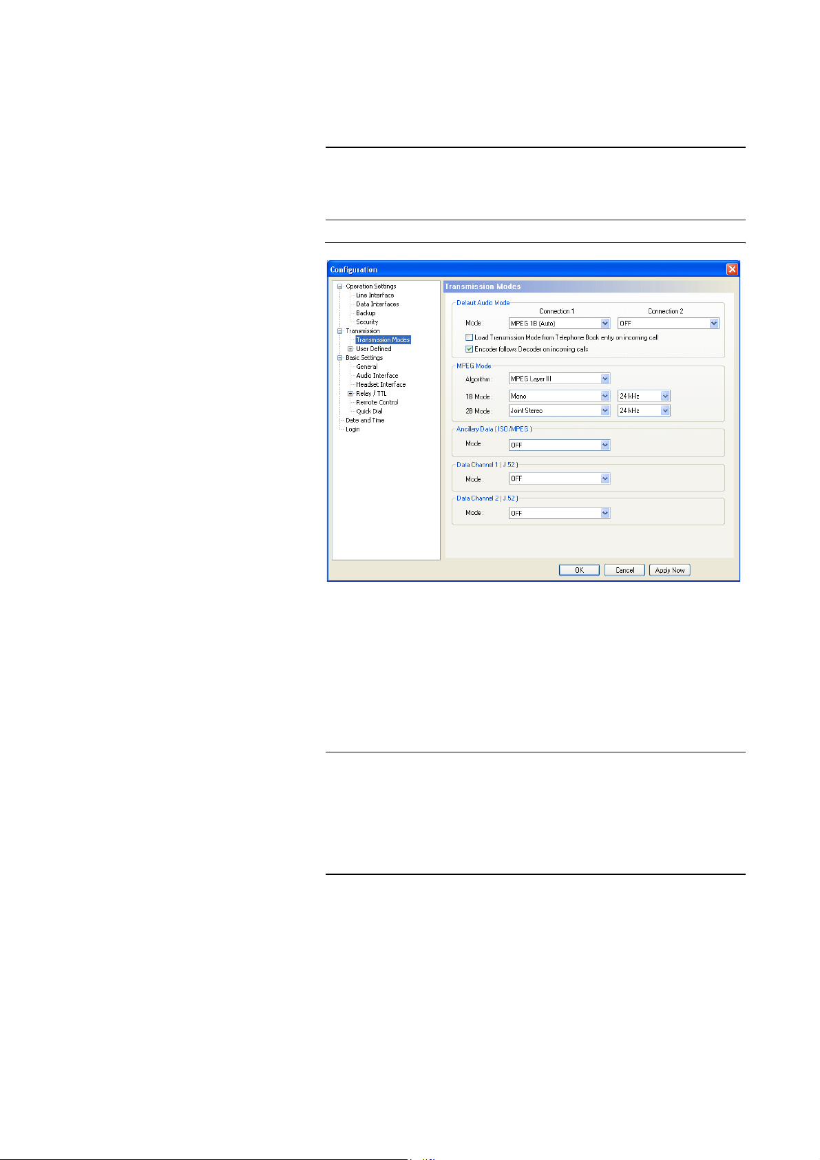
Windows PC Software
5.7.2.2.1 Transmission Modes
Via the configuration menu Transmission Modes you can configure all parameters for the Audio transmission and the transparent data transmission.
TIP
In contrast to AutoDynamicSync (ADS) (see CHAPTER A2, page 137), you
enforce the transmission mode. If you know which system and which transmission procedure is used at the remote side, you should work with a defined
Transmission Mode to avoid missynchronisations.
FIG. 34 TRANSMISSION MODES
NOTE
Default Audio Mode
•With Default Audio Mode you define the transmission mode for each B
channel which is to be displayed by default. Under Mode, the four standard modes (Telephone, 7 kHz (Auto), MPEG 1B (Auto), MPEG 2B
(Auto)) as well as all user defined modes for Connection 1 are available.
If you select OFF, the most recently used mode is always displayed first.
Restrictions Connection 2:
If you have selected the 2 B mode MPEG 2B for Connection 1, it is not possible to select a mode for Connection 2.
If you have selected a 1 B channel MPEG mode for Connection 1, only the
Telephone and 7 kHz modes can be selected for Connection 2.
• If the option Load Transmission Mode from Telephone Book entry on
incomig call is enabled, the transmission mode which is saved together
with the caller number of the incoming call in the telephone book is loaded
automatically (see CHAPTER , page 39) (if the caller is saved in the telephone book and the number is transmitted).
PAGE 64
Page 65

Windows PC Software
• With the option Encoder follows Decoder on incoming calls you make
sure that the encoder works with the same settings (such as e.g. Audio coding algorithm and sampling frequency) as the decoder.
TIP
NOTE
Since some Audio codecs only allow the same parameters in transmit and receive direction, this setting should be always enabled to guarantee maximum
compatibility.
This setting only refers to incoming calls. If you establish a connection yourself, you can select different parameters for Encoder and Decoder if the called
end supports this configuration.
MPEG Mode
Under MPEG Mode, you configure the transmission parameters for the
ISO/MPEG Layer III or Layer II (Option) Audio coding algorithm.
• Algorithm: Please select the desired coding algorithm Layer III or Layer II.
Layer II is only available, if the fee-based option ISO/MPEG Layer II Upgrade
(order number 450305) is enabled.
We recommend - if possible - to use Layer III, since at data rates of maximum 128 kbit/s this algorithm provides much better quality as Layer II
does. Layer II should only be selected if the remote side can only decode
Layer II signals.
• 1 B Mode: Under this setting, you can configure the Audio mode (Stereo,
Joint Stereo, Dual Channel, Mono) and the sampling frequency (16 kHz,
24 kHz, 32 kHz, 48 kHz), if only one B channel (64 kbit/s) is used for an
MPEG connection.
• 2 B Mode: Under this setting, you can configure the Audio mode (Stereo,
Joint Stereo, Dual Channel, Mono) and the sampling frequency
1
(16
kHz, 24 kHz, 32 kHz, 48 kHz), if two B channels (128 kbit/s) are used for
an MPEG connection.
1
If Layer II is used, depending on the signalling not all sampling frequencies are available.
PAGE 65
Page 66

Windows PC Software
ATTENTION In the following, all available transparent data channels are described. Two
Ancillary Data (ISO/MPEG)
physically independent interfaces can be configured according to your requirements.
!
Since the implementation of the data channels is not completely defined, they
usually work only between systems from the same manufacturer.
The usage of an ISO/MPEG Audio coding algorithm
of a transparent inband data channel (Ancillary Data). The data is included in
the MPEG data stream.
NOTE
ATTENTION If you already use an interface for Ancillary Data, you must deactivate the
Please consider that in this way the full bit rate is no longer available for the
Audio signal. The Audio quality is reduced depending on the ancillary data
rate. Special attention should be paid to the fact that the size of the data channel is dynamic: If data is available, a channel with the needed band width is
opened. If no data is to be transmitted, all available bits are used for the Audio coding.
The maximum data rate can be selected under Configuration Æ Data Inter-
faces (see CHAPTER 5.7.2.1.2, page 57).
In maximum, 15% of the gross MPEG data rate can be used for ancillary data
(e.g. at 128 kbit/s Æ maximum ancillary data rate: 19,2 kbit/s)
•Under Mode you decide which physical interface (ON - using Data Inter-
face 1 or ON - Using Data Interface 2) is used for the ancillary data.
Please select OFF, if you do not want to transmit ancillary data.
Data Channel 1/2 (J.52)
data interface which is used under Data Channel 1/2 (J.52) by selecting OFF.
1
allows a transmission
!
NOTE
In addition to the transmission of Ancillary Data in the MPEG data stream, a
further transparent data channel (LSD Low Speed Data) can be used when the
ITU-T Standard J.52 is used. For transmitting LSD, a channel with fixed band
width is opened in parallel to the Audio signal.
If you selected 7 kHz as Audio mode, you can use one transparent data channel for each B channel independently from each other.
PAGE 66
1
The transmission of Ancillary Data is currently only possible with ISO/MPEG Layer III.
Page 67
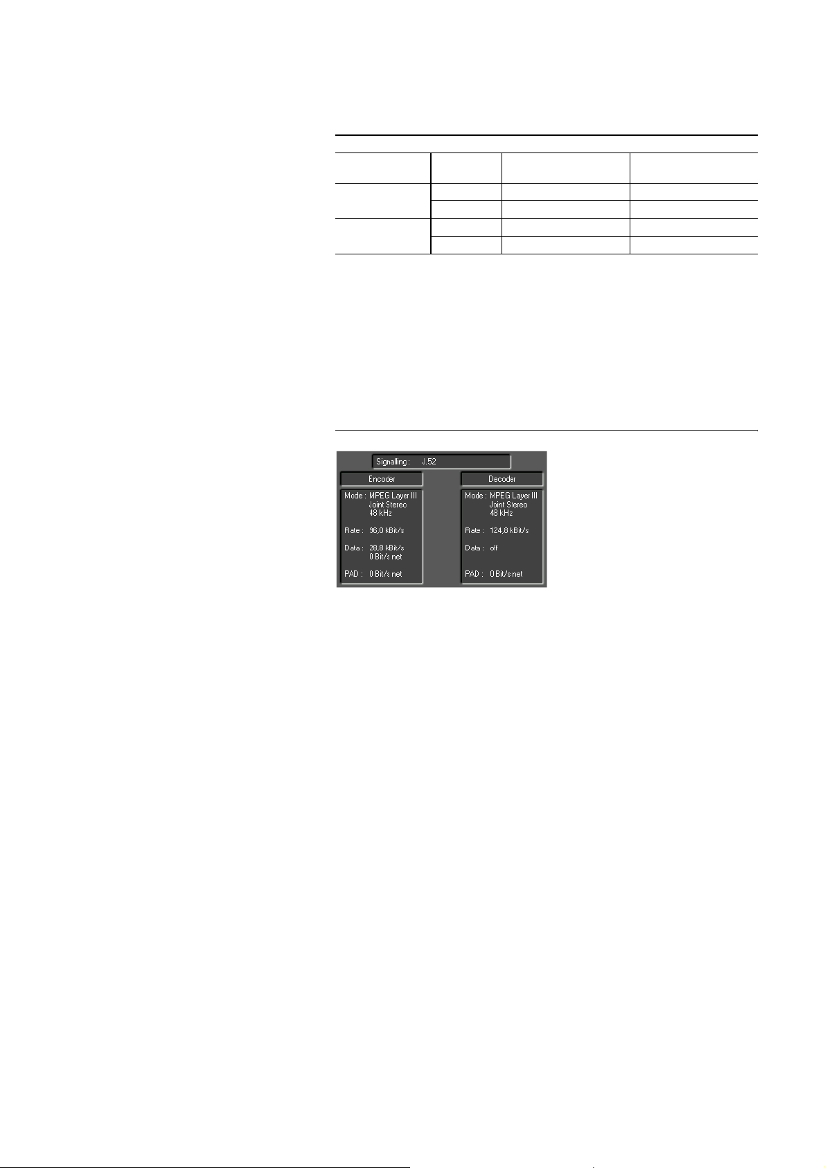
Windows PC Software
• The actual available data rate depends on the number of the B channels
used and the Mode setting. Please select OFF, if you do not want to use the
data channel.
TAB. 2 BIT RATE IN THE J.52 DATA CHANNEL
Mode
Data Channel 1/2
LOW
HIGH
Number of
B Channels
1 56 kbit/s 6,4 kbit/s
2 112 kbit/s 12,8 kbit/s
1 48 kbit/s 14,4 kbit/s
2 96 kbit/s 28,8 kbit/s
Bit Rate
MPEG Audio
Bit Rate
Data Channel
The actual bit rates are displayed in the main window:
– Rate: actual Audio data rate
– Data: band width J.52 data channel and
actual net bit rate (x kbit/s net)
– PAD : actual net bit rate (x kbit/s net) Ancillary Data
FIG. 35 DISPLAY OF THE BIT RATES IN THE MAIN WINDOW
PAGE 67
Page 68
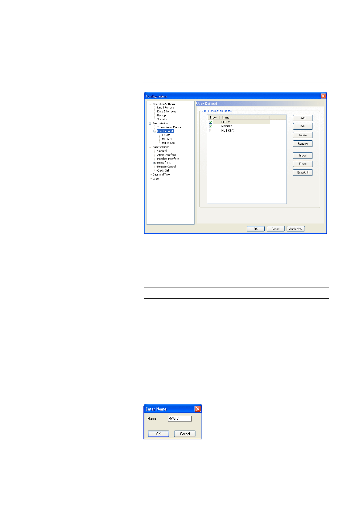
Windows PC Software
5.7.2.2.2 User Defined
The configuration User Defined allows you to generate your own transmission modes. These user defined modes are display when a call is established
via the front keypad and display as well as in the main window of the PC Software.
FIG. 36 USER DEFINED TRANSMISSION MODES
NOTE
User Transmission Modes
In the list User Transmission Modes, all already created transmission
modes are displayed.
Up to 20 different modes can be saved.
•Via the checkbox Show you can decide if the selected transmission mode
is to be displayed in the PC Software or/and in the front display of the system. If you display too many entries, the selection of the transmission
mode becomes very unclear for the user - especially when using the front
display - therefore you should not display modes that are not required.
•Under Name, the name of the transmission mode is displayed. The length
of a name must not exceed eight characters.
•With Add a new transmission mode can be created. After entering the
name, the configuration dialogue (see page 69) is displayed.
FIG. 37 ENTER A NAME
PAGE 68
•The Edit button allows you to edit the selected transmission mode.
Page 69
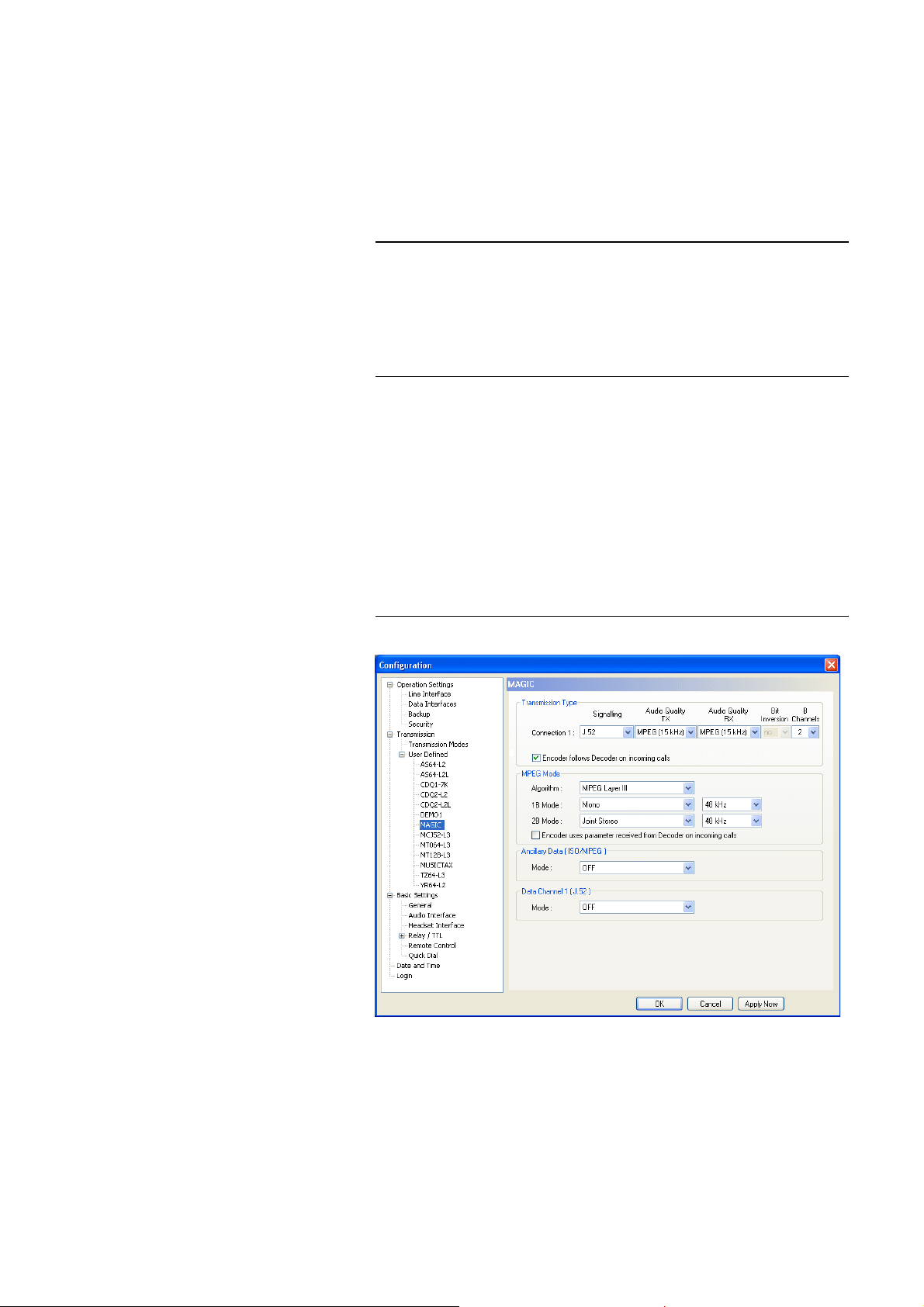
Windows PC Software
•With Delete you can delete a mode which is not required anymore. You
have to confirm if you really want to delete the mode.
• To change the name of a transmission mode, you can press the button Re-
name. The length of the name must not exceed eight characters.
• Via the function Import you can load a transmission mode from a data carrier.
NOTE
During the installation common transmission modes for a variety of Audio
codecs from other manufacturers are saved in the directory
<Installation directory>\transmissionmodes
Further details concerning the transmission modes can be found in
CHAPTER A3, Page 138.
Via the file browser you select the file which you want to import. Transmission mode files have the extension
.tmm.
•With Export you can store individual modes on a data carrier. Via Browse
you select the storage location.
• To store all modes on a data carrier, please use the function Export All and
select the desired target directory. Each mode is saved in a separate file.
If you create a new transmission mode or if you edit an existing one, the configuration dialogue is displayed.
FIG. 38 CONFIGURATION DIALOGUE USER DEFINED TRANSMISSION
MODES
Transmission Type
First, select the transmission type for Connection 1:
•Under Signalling the following procedures are available:
– Telephone: Normal telephone connection with 3.1 kHz band width in
transmit and receive transmission.
PAGE 69
Page 70

Windows PC Software
– J.52: IUT-T Standard, which allows a so-called Capability Exchange
and a permanent delay compensation2 when 2 B channels are used. Depending on the implementation, transparent data channels can be also
transmitted. An unsymmetrical Audio transmission (e.g. MPEG with 2
B in transmit direction, 7 kHz in receive direction) is also possible. This
procedure is supported by several manufacturers (e.g. MAYAH Centauri). For MAGIC DC7/AC1 this procedure is set by default.
– OFF: No signalling is used. The encoded Audio data is transmitted
without any further framing. With this way of signalling, only one B
channel can be used. The procedure is possible with almost every available Audio codec on the market.
If G.722 (7 kHz) is selected as Audio quality (see below), the so-called
SRT procedure (Statistical Recovered Timing) is used when no signalling is selected.
– MusicTaxi: This proprietary signalling is used by Audio codecs from
the company Orban (former Dialog4) and has been also implemented
by some other manufacturers for compatibility reasons. 2 B channels
can be transmitted. The Audio transmission is symmetrical, i.e. the
same coding algorithm must be used in transmit and receive direction.
– CCS-L2: A further proprietary signalling from the company Musicam
USA (in Europe formerly CCS). The procedure supports only a symmetrical Audio transmission with ISO/MPEG Layer II with up to 2 B
channels. Therefore, the fee-based option ISO/MPEG Layer II Upgrade
(order number.: 450305) is required to use this signalling.
1
NOTE
•Under Audio Quality TX you select the Audio quality for the transmit di-
rection. Depending on the selectedTransmission Type the following settings are available:
– G.722 (7 kHz)
– MPEG (15 kHz)
• The Audio quality in receive direction (Audio Quality RX) can only be selected for the transmission type J.52 , since all other procedures only allow
a symmetrical Audio transmission. The following options are available
3
– G.722 (7 kHz)
– MPEG (15 kHz)
•The option Bit Inversion allows an inversion of the encoded Audio signal
and is only available when OFF is selected as signalling type.
If you defined only a 1B connection for Connection 1, you can define additionally a Telephone or 7 kHz (Auto) connection for the second B channel.
You can also establish connections with two different algorithms to two different partners at the same time.
:
PAGE 70
1
Capability Exchange: At the beginning of the connection, the systems exchange information
about how many B channels are possible, which Audio coding algorithms and specific codec parameters are available etc. After this exchange, the best possible transmission mode is set automatically. However, you have also the possibility to force a certain procedure, e.g. when you only
need a 7 kHz connection.
2
B channels are routed individually in the ISDN network. When Audio signals are transmitted
with 128 kbit/s, the two B channels have to be set together at the same time at the receiver which
is done by a delay compensation. This procedure is called Inverse Multiplexing. If B channels are
re-routed in the network because of line errors during a connection, an Audio transmission with
a static delay compensation, which was measured at the beginning of the connection, would not
work anylonger. J.52 adapts the delay compensation dynamically and is protected from delay
variations.
Page 71

Windows PC Software
• With the option Encoder follows Decoder on incoming calls you ensure
that the Encoder always works with the same settings (such as e.g. Audio
coding algorithm and sampling frequency) as the Decoder does.
TIP
Since some Audio codecs only allow the same parameters in transmit and receive direction, this setting should be always enabled to guarantee maximum
compatibility.
This setting only refers to incoming calls. If you establish a connection yourself, you can select different parameters for Encoder and Decoder if the called
end supports this configuration.
MPEG Mode
Identical settings as under Transmission Modes
→
MPEG Mode (see page
65).
Ancillary Data (ISO/MPEG)
Same settings as under Transmission Modes → Ancillary Data
(ISO/MPEG) (see page 66).
Data Channel 1/2 (J.52)
Same settings as under Transmission Modes → Data Channel 1/2 (J.52)
(see page 66).
3
If you select G.722 (7 kHz), the system signals to the remote side that only a 7 kHz Decoder is
available, although you have an MPEG Decoder with MAGIC AC1. In this way, the remote side
is forced to encode with 7 kHz.
PAGE 71
Page 72
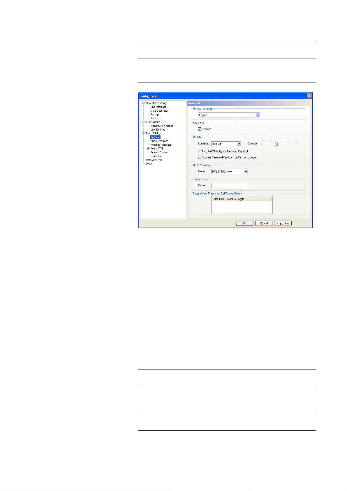
Windows PC Software
5.7.2.3 Basic Settings
NOTE
5.7.2.3.1 General
All settings made under Basic Settings cannot be saved as Preset (see
CHAPTER 5.7.3.3).
FIG. 39 GENERAL
NOTE
Display Language
• Currently the languages English and German are supported as display
languages.
Key Tone
• To active the key tone for the system, please select the check box Enabled.
Display
The Display has a backlight. Under Backlight you can set it on permanently
if you select On. If Auto off is selected, the backlight is automatically turned
off 60 seconds after the last keystroke. The backlight can be activated again by
pressing any key (e.g.
Please notice that if the key lock is enabled, the backlight is not activated before you press the key sequence
• With the slide controller Contrast you can set the desired contrast for the
display within the range of -16 ... 15. The default setting is 0.
OK
)
MENU
.
*
PAGE 72
NOTE
To use the following functions a user or administrator password must be entered under Login (see CHAPTER 5.7.2.5).
Page 73
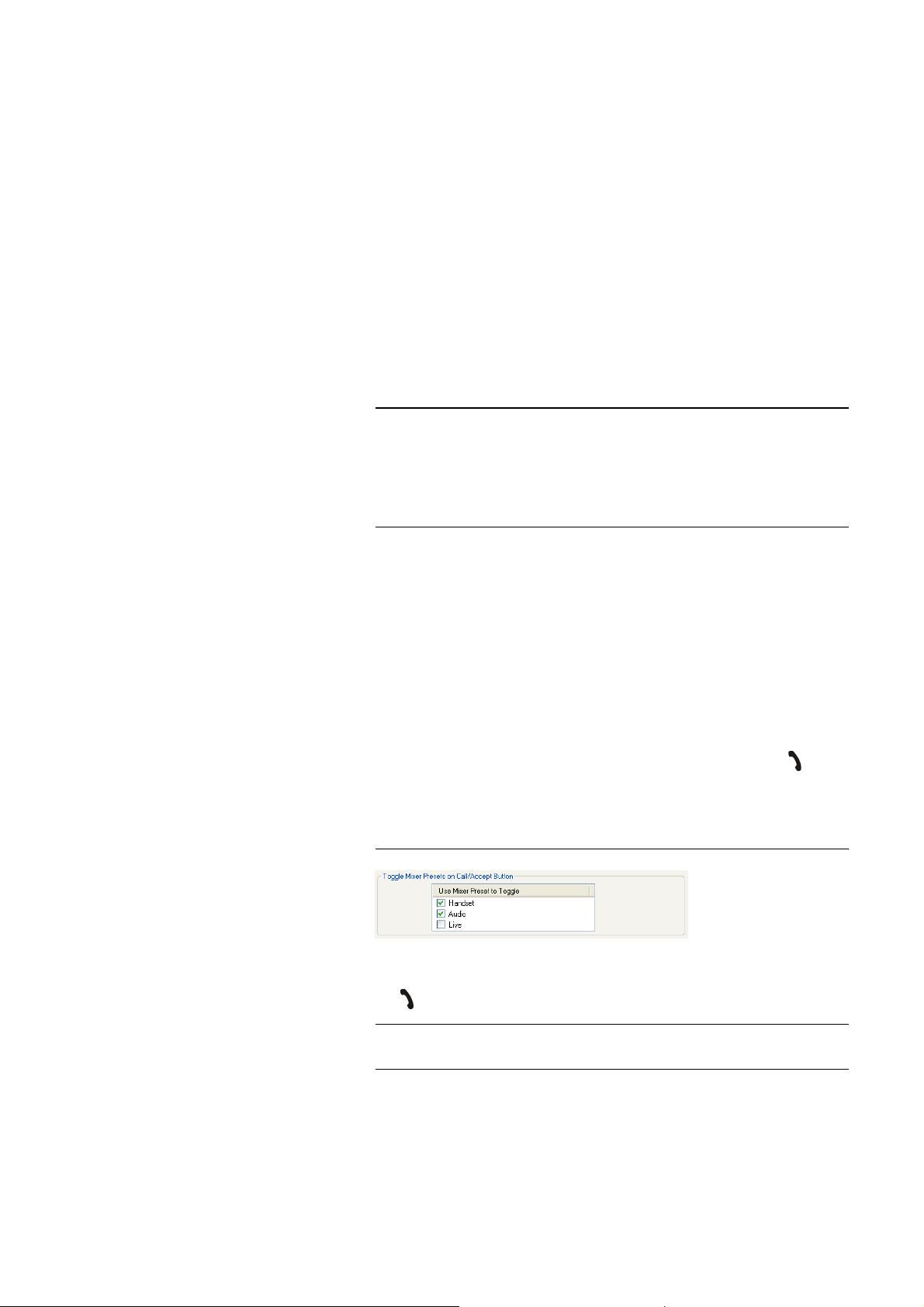
Windows PC Software
• If the option Switch Off Display on Password Key Lock is selected, the
display is automatically switched off after 60 seconds after logging out.
Any keystroke activates the display. Dialling is possible.
• If the function Activate Password Key Lock on Password Logout is enabled, the key lock is automatically activated 60 seconds after logging out.
Next to the clock a key symbol is displayed. In addition to the configuration lock by entering a password under Login, dialling via the numerical
keypad is no longer possible.
RS232 Interface
If you want to operate the system with a PC, you need to configure the data
rate of the interface. The following five baud rates are available: PC & Keypad
(9600, None), PC (19200, None), PC (38400, None), PC (57600, None), PC
(115200, None). The default setting is PC (38400, None).
NOTE
The MAGIC DC7/AC1 Keypad supports only a baud rate of 9600 Baud.
Therefore, if you use the keypads, always select PC & Keypad (9600, None).
This baudrate can also be selected if a PC is used.
If a PC is connected via the RS232 interface, the selected baudrate must be
identical with the baudrate of the COM interface.
System Name
Under System Name you can enter a name for the system. The name is displayed in the optional software plug-in MAGIC DC7/AC1 LAN (see
CHAPTER 9) which allows a simultaneous control of up to 10 systems.
Toggle Mixer Presets on Call/Accept Button
The function Toggle Mixer Presets on Call/Accept Button allows a fast
switching between maximum three Mixer Presets by pressing the button
on the front keypad.
All already existing Mixer Presets are displayed in the list.
FIG. 40 SELECTION OF THE MIXER PRESETS
NOTE
By activating the Checkbox you select which Mixer Presets are loaded when
the button is pressed.
Please consider also the function for the emulation of the 15-kHz/PKI 7-kHz
ISDN Telephones (see CHAPTER 5.8.7).
PAGE 73
Page 74
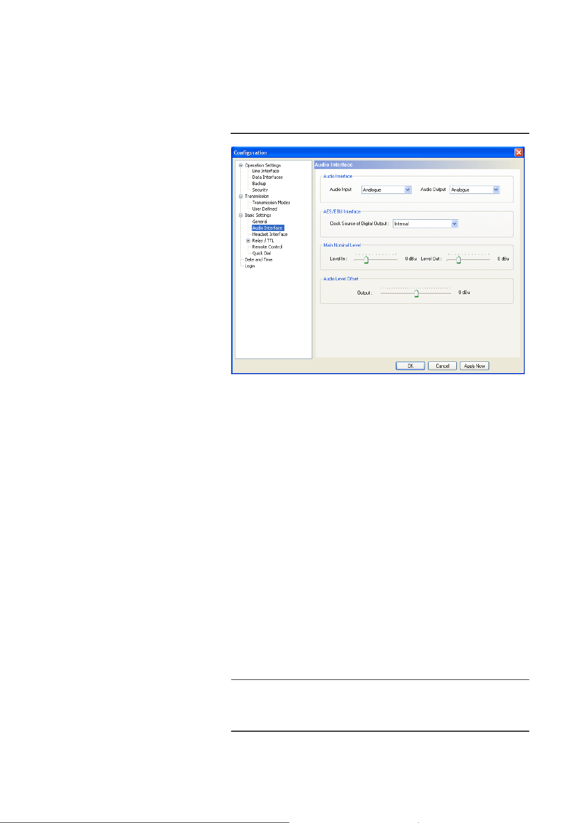
Windows PC Software
5.7.2.3.2 Audio Interface
MAGIC DC7/AC1 supports analogue as well as optionally digital AES/EBU
Audio interfaces (order number 430230). If the digital interface is used, separate Sample Rate Converters for input and output are available which supersedes external adjustments for different digital sources.
FIG. 41 CONFIGURATION OF THE AUDIO INTERFACES
NOTE
Audio Interface
•The operating modes analogue or digital can be individually adjusted for
the Audio Input and the Audio Output.
AES/EBU Interface
• If you select the option digital for the output, the configuration for the
AES/EBU Interface is displayed. Under Clock Source of digital output
the following settings are available:
– Internal: The AES/EBU output clock is adapted to the internal system
clock.
– External: The AES/EBU output clock is adapted to the external clock
which is supplied by the Audio 2/CLK IN interface. The clock frequency of the supplied clock needs to be 48-kHz.
– Recovered: The AES/EBU output clock is recovered from the digital
input signal of the Audio 1/AES IN interface. This configuration should
be selected if you use the digital input of the system. In this way, a synchronous working of the transmission chain is ensured.
An AES/EBU input always works with recovered clock. Therefore, only a
configuration of the output is required.
For clock synchronisation with other systems, you can use the clock output
Audio 2/CLK OUT. The clock frequency of the output clock is 48-kHz.
PAGE 74
Page 75

Windows PC Software
Main Nominal Level
• If you select the analogue mode for input or output, the corresponding
slide controller is displayed to set the nominal Audio level of the XLR Audio interfaces (Main Nominal Level). The main nominal level can be adjusted separately for the input (Level In) and for the output (Level Out)
within a range of -3 ... +9 dBu in steps of 1-dB. The head room is 6 dB. If
you want to have the maximum level of 15 dBu for the system, you need
to set 9 dBu as main nominal level. The default setting is 0 dBu.
Audio Level Offset
• Via the scroll bar Audio Level Offset you can adjust the Audio Output
signal within the range of -16 ... +15 dBu digitally in 1-dB steps. The default setting is 0 dBu.
NOTE
Changing the Audio Level Offset is only seldom required if e.g. the signal of
the remote side is always much too loud or much too low. Please note that if
the Audio level Offset is increased, the head room is decreased correspondingly.
PAGE 75
Page 76
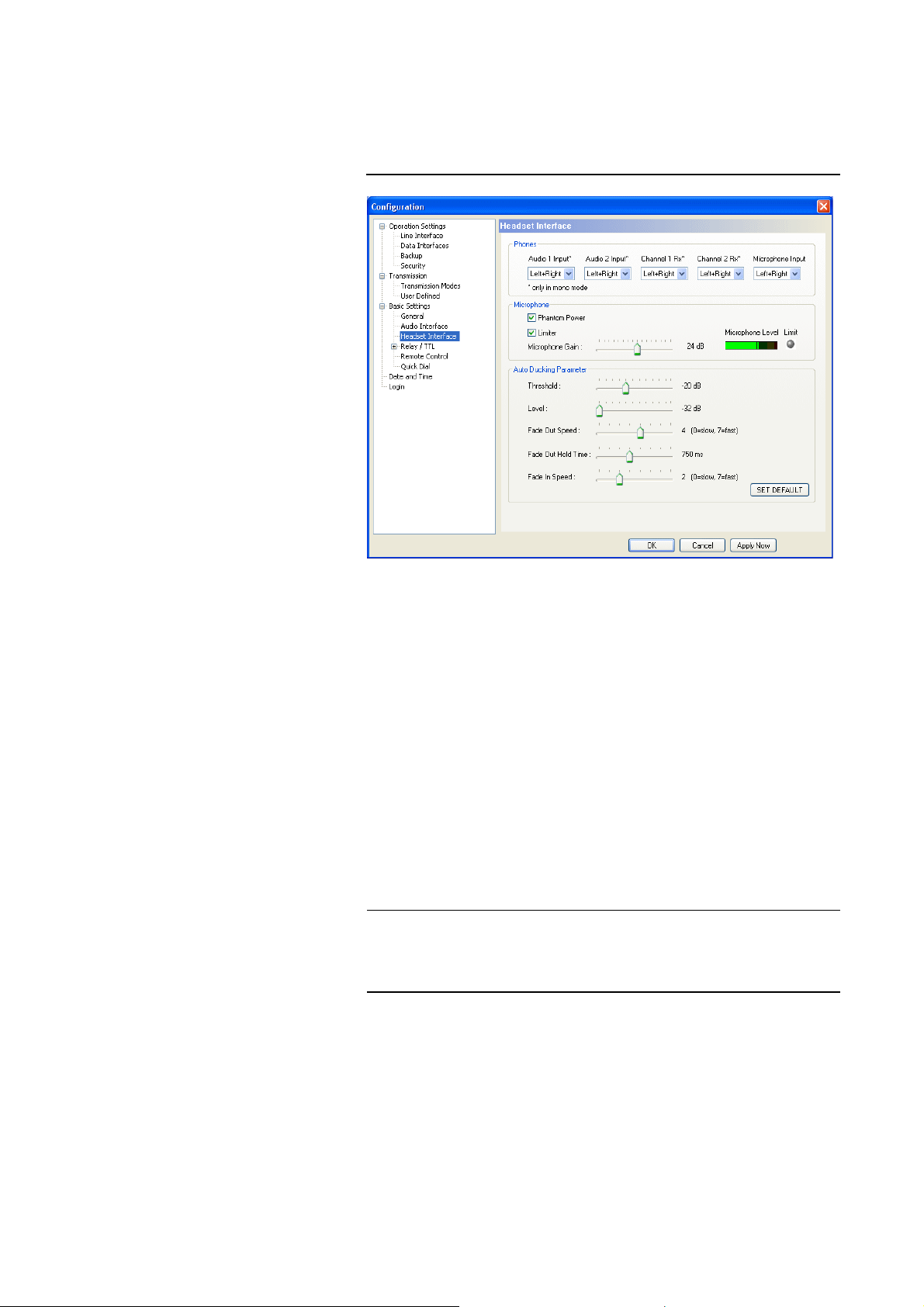
Windows PC Software
5.7.2.3.3 Headset Interface
MAGIC DC7/AC1 provides a headset interface to connect a standard professional headset (e.g. beyerdynamic DT291 PV).
FIG. 42 CONFIGURATION OF THE HEADSET INTERFACE
NOTE
Phones
Via the setting Phones you configure the Audio signal assignment of the
headphones.
• For all available signal sources Audio 1 Input, Audio 2 Input, Channel 1
Rx, Channel 2 Rx and Microphone Input you can decide if you want to
hear the signal - as soon as it is activated - either on both channels
(Left+Right) of the phones or only on the Left or Right channel of the
phones.
Reasonable applications are Live reports of commentators or translations
of interpreters: For example, the original signal of the speaker (e.g. via Au-
dio 1 Input or Channel 1 Rx) is available on the left channel and the interpreter’s own translated signal (e.g. via Microphone Input) is available on
the right channel for checking purposes.
The settings for the different signal sources apply only for transmissions in
Mono. During a Stereo transmission, the left channel is always available on
the left earphone and the right channel is always available on the right earphone. The microphone signal is generally only available in Mono.
Microphone
PAGE 76
Under Microphone you configure the microphone input of the headset interface.
• If your microphone requires phantom power, you can activate it via the
option Phantom Power. A voltage of 12V is applied to the microphone
wires.
Page 77
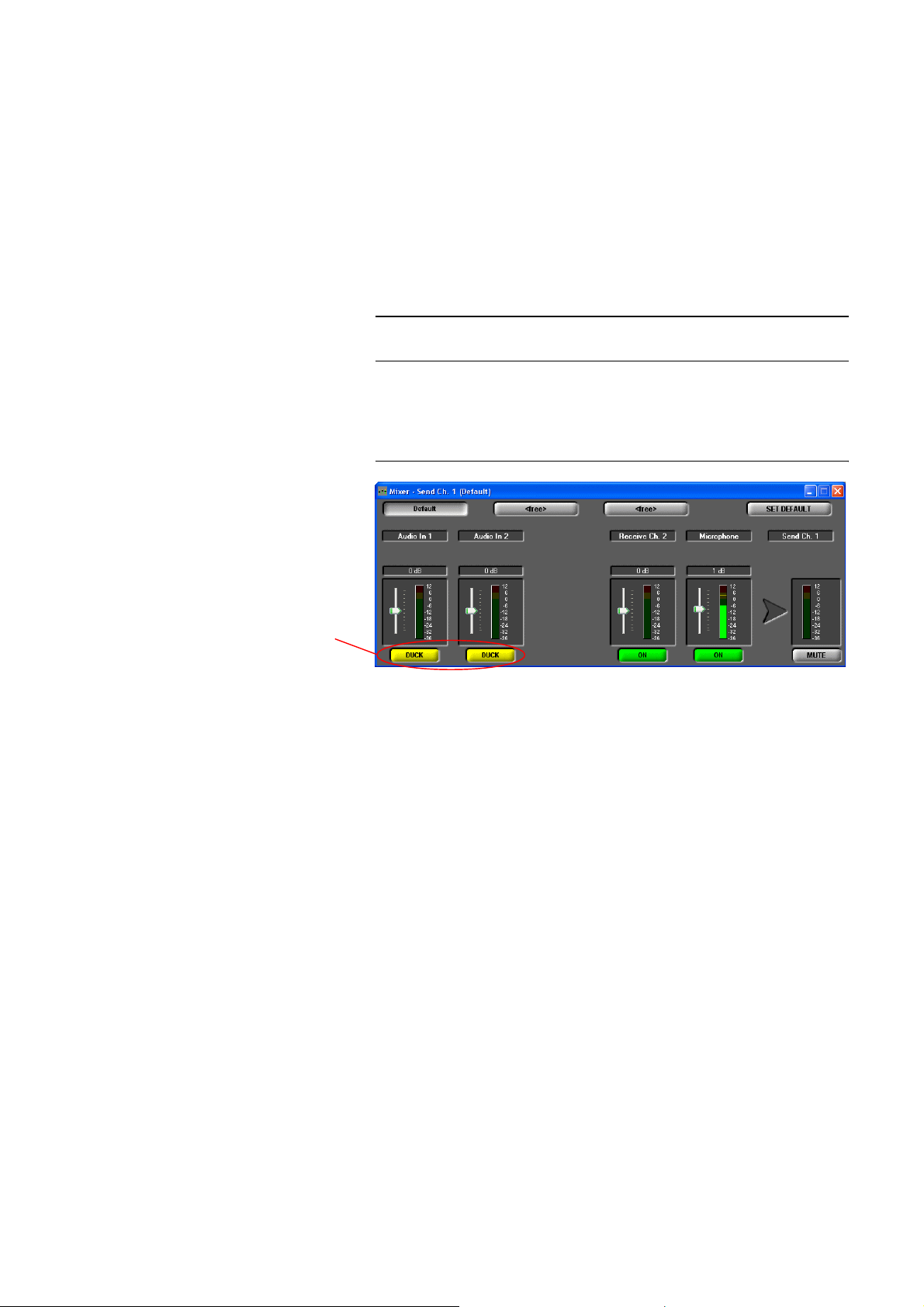
Windows PC Software
• To avoid an overdrive of the system, the microphone input has a switchable Limiter.
•Via Microphone Gain you can adapt the sensitivity of your microphone
to the limiter. The gain can be set within the range of 0 ... +45 dB in 1-dB
steps. For a simple adaptation you should use the Microphone Level.
When the setting is optimal, the Limiter LED should never be illuminated
or only for a short time. The setting Limiter is not relevant for the level setting.
Auto Ducking Parameter
NOTE
Auto ducking
activated
This function is only available if the fee-based option Mixer Tool Plug-In (order number 430201) is enabled.
For the two Audio inputs, the Autoducking function can be activated if the
microphone is used. As soon as you talk into the microphone, the level of the
Audio inputs is turned down.
FIG. 43 ACTIVATED AUTO DUCKING IN THE AUDIO MIXER
The following parameters can be changed to adjust the Autoducking behaviour:
• Threshold: Via this setting you select the threshold value at which the reducing of the Audio input level starts. Available range: -32... 0 dB in 1-dB
steps. Default setting: -20 dB.
• Level: This setting defines the level to which the Audio input level is to be
reduced. Available range: -32... 0 dB in 1-dB steps. Default setting: -32 dB.
• Fade Out Speed: Here you select the speed with which the Audio input
signal is turned down. Available range: 0 (slow) ... 7 (fast). Default setting: 4.
• Fade Out Hold Time: This value defines the minimum time during which
the Audio input signal is faded out. If nobody talks into the microphone
anylonger, the signal is faded in again after the time you set here. Available range: 0 ... 1750 ms. Default setting: 750 ms.
• Fade In Speed: Here you select the speed with which the Audio input signal is faded in. Available range: 0 (slow) ... 7 (fast). Default setting: 2.
• The button Set Default resets all parameters to the default settings.
PAGE 77
Page 78
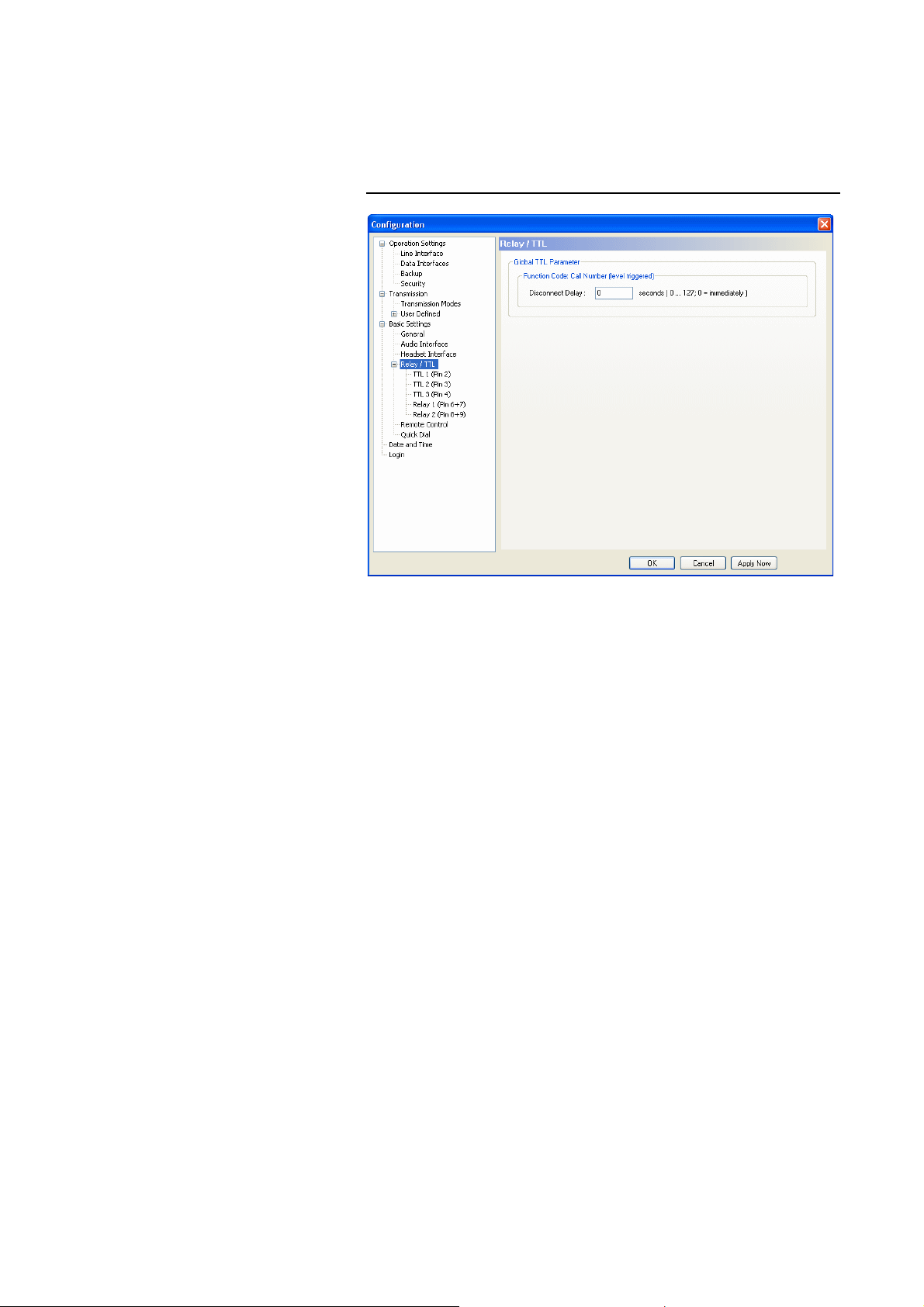
Windows PC Software
5.7.2.3.4 Relay/TTL
The MAGIC DC/AC1 System has three GPIO Pins (TTL) which can be programmed individually as input or output. Additionally, two relays are available.
FIG. 44 GLOBAL SETTINGS
Under Relay/TTL, general parameters for the GPIO contacts can be configured.
Global TTL Parameter
•For the Function Code: Call Number (level triggered) (see page 79) you
can program a delay for the disconnection within the range of 0...127 seconds. If you select 0, the connection is dropped immediately.
This setting is helpful, e.g. if you realised an automatic dialling via VOX
control. If nobody is speaking, the connection would be dropped immediately by default. If you have set a delay, short breaks in the speech/Audio
signal do not result in an immediate disconnection.
The functionality of a TTL Pin - Input or Output - can be selected with the option Direction.
The following description applies to all three configuration windows TTL1
(Pin 2), TTL2 (Pin 3) and TTL3 (Pin 4).
PAGE 78
Page 79
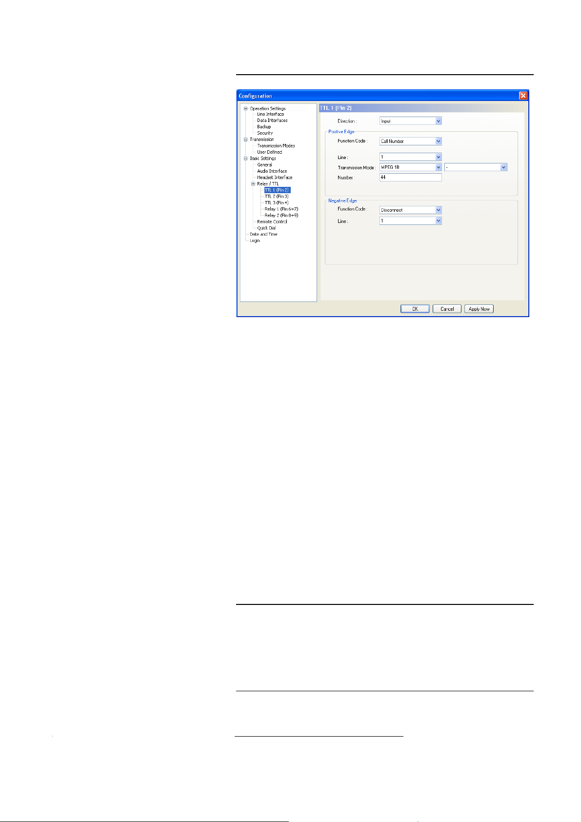
TTL Pin as Input
FIG. 45 TTL PIN AS INPUT
Windows PC Software
TIP
If you use a TTL Pin as Input, you can configured two different functions
when the edges change:
• Positive edge: The event is triggered when the voltage at the TTL Pin
changes from 0V to+5V.
• Negative edge: The event is triggered when the voltage at the TTL Pin
changes from +5V to 0V.
The following Function Codes can be selected:
– - (Not used): No function, the Pin is not used. This option is to be se-
lected for remote control via the function Output
→
Remote TTL In-
put (see page 82).
– Call Number :
With this function you can establish a connection with a certain calling
Number. With Line you select the line (1 or 2) on which the connection
is to be established (only in the ISDN operating mode). Under Trans-
mission Mode you select the desired mode for the transmission.
– Call Number (level triggered):
Same function as above, however, except that here the level is analysed
and not the edge.
With this function, you can configure an automatic redialling to ensure that
the partner is automatically re-dialled if there is an unexpected disconnection. Please configure this function under Positive edge. Since the TTL Pin
has a 5V level by default, a connection to the given number is established immediately.
Attention: This function can only be ended by setting the Pin to the 0V level
or switching off this function via the configuration.
1
– Disconnect: Disconnect: By enabling this function a connection on
the indicated line (1 or 2) can be disconnected.
1
Except function code Call Number (level triggered), if this code is selected only one edge can be
used.
PAGE 79
Page 80

Windows PC Software
– Load Preset: Via this function you can load a Preset which you must
indicate under Preset.
– Backup Alarm Signal: With this function it is possible to feed in an ex-
ternal TTL alarm signal whereby an ISDN Backup (see CHAPTER
5.7.2.1.3, page 58) is established.
– Backup Disable: Via this external control signal you can avoid that an
ISDN Backup is established although the Backup Alarm Signal is active (see CHAPTER 5.7.2.1.3, page 58).
– Set Information Base Entry: Special function for projects.
– String Command: Special function for projects.
Example:
With TTL1 a call is to be accepted on line 1. The system is to be configured automatically to the MPEG 1B Mode. After the conversation is
over, the connection is to be dropped also with TTL1.
Programming:
Positive edge:
Function Code: Call Number
Line: 1
Transmission Mode: MPEG 1B
Phone Number: -
Negative edge:
Function Code: Disconnect
Line: 1
FIG. 46 FUNCTION SEQUENCE OF THE EXAMPLE
Switch
Switch is open:
Pin 2 = TTL 1 lies at +5 V (via internal 10 kOhm series resistor)
Switch is closed:
Pin 2 =TTL 1 is set to 0V (Pin 5):
1
6
9-pol. SUB-D male
to MAGIC DC7/AC1
(TTL/RELAY)
5
9
existing connection is dropped
Switch is opened:
Pin 2 =TTL 1 is set to +5V:
Incoming call is accepted and connection established
PAGE 80
Page 81
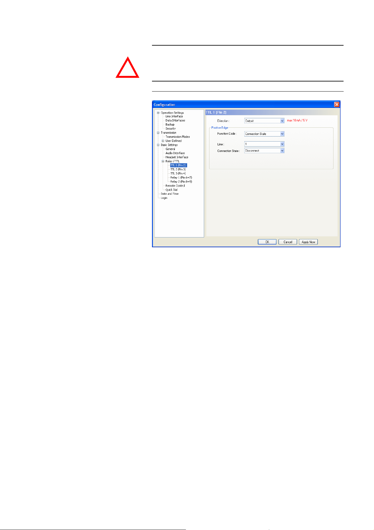
Windows PC Software
TTL Pin as Output
ATTENTION Please note that the maximum switching current is 10 mA and the maximum
switching voltage is 5V per TTL output.
!
FIG. 47 TTL PIN AS OUTPUT
If a TTL Pin is configured as Output, the event is signalled when the voltage
at the TTL Pin changes from 0V to +5V.
Under Positive edge you can select the following Function Codes:
– Fixed Low (0V): The TTL Pin is fixed to 0V.
– Fixed High (5V): The TTL Pin is fixed to +5V.
– PC Controlled: Special function for projects.
– Connection State: Via this function you can signal the connection state of
a line. Please select the desired connection state under Connection State.
The following options are available:
– Disconnect
– Call Out
– Call In
– Connect
– Call Setup
Under Line you can select for which line you want to signal the connection
state. In addition to line 1 and line 2 you can monitor the connection status
of both lines if you select all. As soon as one of the two lines meets the criteria, the signal is triggered at the TTL Pin.
– Information Base Entry: Special function for projects.
– System Alarm Pending: This function signals a pending system alarm
(see CHAPTER 5.9.1).
PAGE 81
Page 82

Windows PC Software
– Remote TTL Input: If this function is selected, you can signal the TTL sta-
tus of the selected Remote TTL input Pin (1, 2, 3) of the remote system. In
this way. remote systems can be controlled remotely or information about
the hardware status can be transmitted. On the remote side the function In-
put
→
- (not used) must be programmed for the corresponding TTL Pin
to enable remote control. If a TTL Pin of the remote side is configured as
output, the status of the Pin is transmitted.
– Inverted Remote TTL Input: Same function as above, except that here the
inverted signal is transmitted.
– Remote PC Controlled: Special function for projects.
– MPEG Decoder synced: If the ISO/MPEG Audio decoder is synchro-
nised, the TTL Pin is set.
– Backup Established: If you activated the Backup function of the system
(see CHAPTER 5.7.2.1.3, page 58), you can signal the backup status
(Backup established Yes/No) via this function.
– Backup Error: If you activated the Backup function of the system (see
CHAPTER 5.7.2.1.3, page 58) and the Backup could not be established for
some reason, the TTL Pin is set. The Pin is also set when the Backup Test
failed (see page 60).
PAGE 82
Page 83
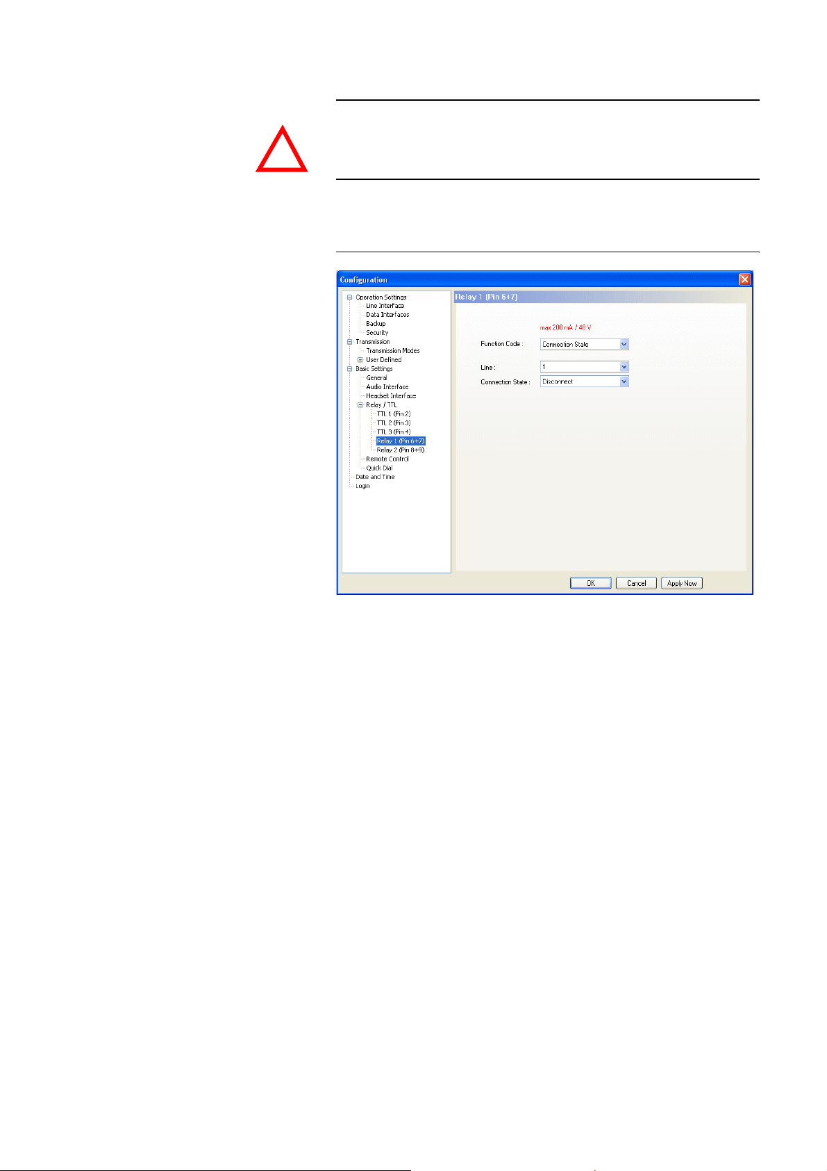
Windows PC Software
Relay
ATTENTION Please consider that the maximum switching current is 200 mA and the max-
imum switching voltage is 48V per relay output.
!
The following description is valid for both configuration windows Relay 1
(Pin 6+7) and Relay 2 (Pin 8+9).
FIG. 48 RELAY
The functions for programming the relays are identical with the function
codes for the TTL output. The following options (Function Codes) are available:
– Always open: The relay contacts are always open.
– Always closed: The relay contacts are always closed.
All further function codes are explained under TTL Pin as Output (Page 81).
PAGE 83
Page 84
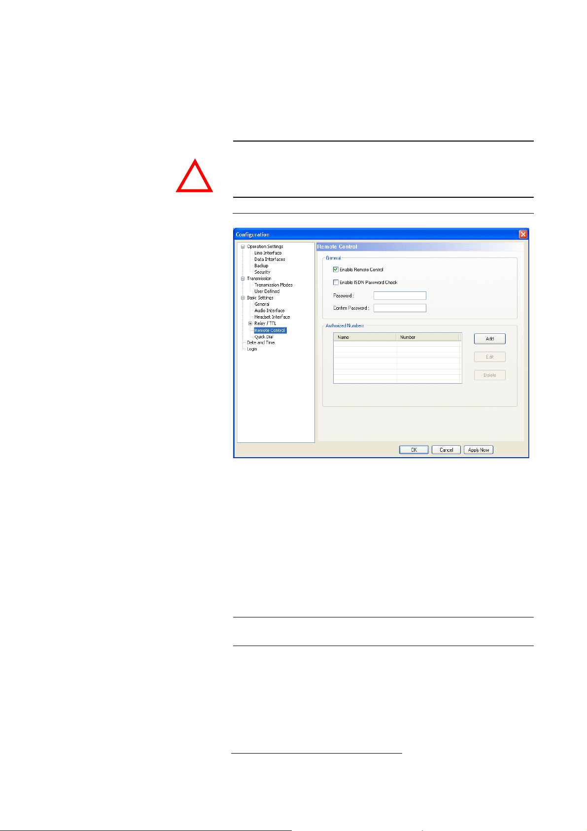
Windows PC Software
5.7.2.3.5 Remote Control
ATTENTION Without any further security measures, anybody who knows the calling
General
To allow remote control for the system (see CHAPTER 8, page 117), you must
activate the function Enable Remote Control.
number of the system and has the fee-based Option: Remote Control Soft-
ware can control the system remotely.
!
Therefore, please activate the security system described below at any rate.
FIG. 49 REMOTE CONTROL
NOTE
By assigning a password, the caller needs to authorise himself first before he
can control the system remotely. The password check can be done in two different ways:
• If the option Enable ISDN Password Check is activated, the password
check is done in the D channel (signalling channel) of th e ISDN connection.
If the passwords do not match, the caller is rejected immediately without
establishing a connection
1
.
If the password check is successful, the call is accepted automatically, even
if the automatic answer of calls is not enabled (see Page 54, Enable Auto
Answer).
The password check in the D channel is only available if the feature sub
addressing is enabled for the ISDN connection.
• If this function is not supported by the ISDN connection, the password
check is not done before the connection has been established.
A call to the system which is to be controlled remotely must be accepted
manually, if the automatic answer of calls is not activated (see Page 54, Enable Auto Answer).
1
In this case, the caller does not have to pay any connection charges.
PAGE 84
Page 85
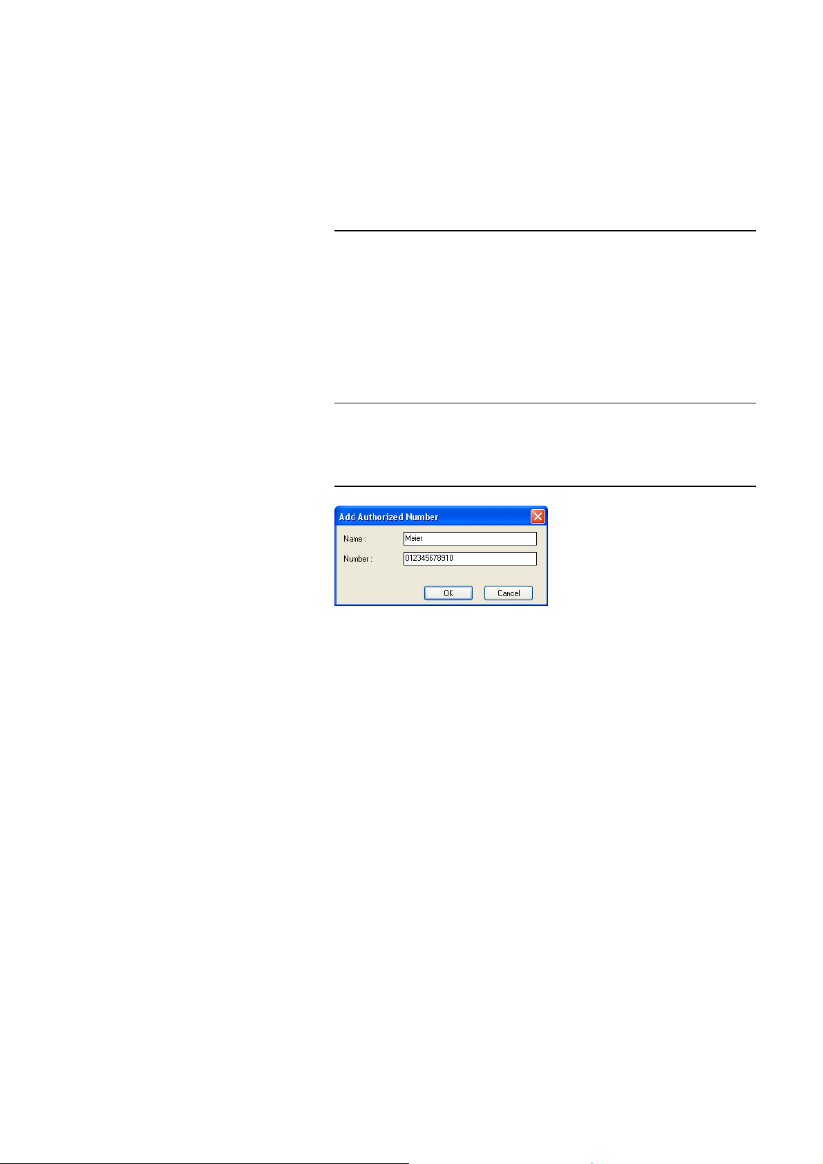
Windows PC Software
The password has to be entered under Password and confirmed by retyping
it under Confirm Password.
Authorized Numbers
Via the function Authorized Numbers a remote control access protection can
be realised. Only person whose number is entered in the list can control the
system remotely. Please enter Name and calling Number for each list entry.
NOTE
Please consider that only numerical characters which are actually entered are
analysed, i.e. if you only enter „130“, all participants with a calling number
which ends with „123“ are allowed to call the system.
The total character length of all entered telephone numbers must not be
higher than 127. With an average length of a telephone number of 12 characters about 10 calling numbers can be saved.
For this functionality the calling number of the participants in the list needs
to be transmitted (CLIP
a
Calling Line Identification Presentation
a
function).
•With Add you can dd a new entry.
FIG. 50 ADDING AN ENTRY
• The button Edit allows to edit already existing entries
•With Delete an entry can be deleted. For safety reasons you must confirm
that you really want to delete the entry.
PAGE 85
Page 86
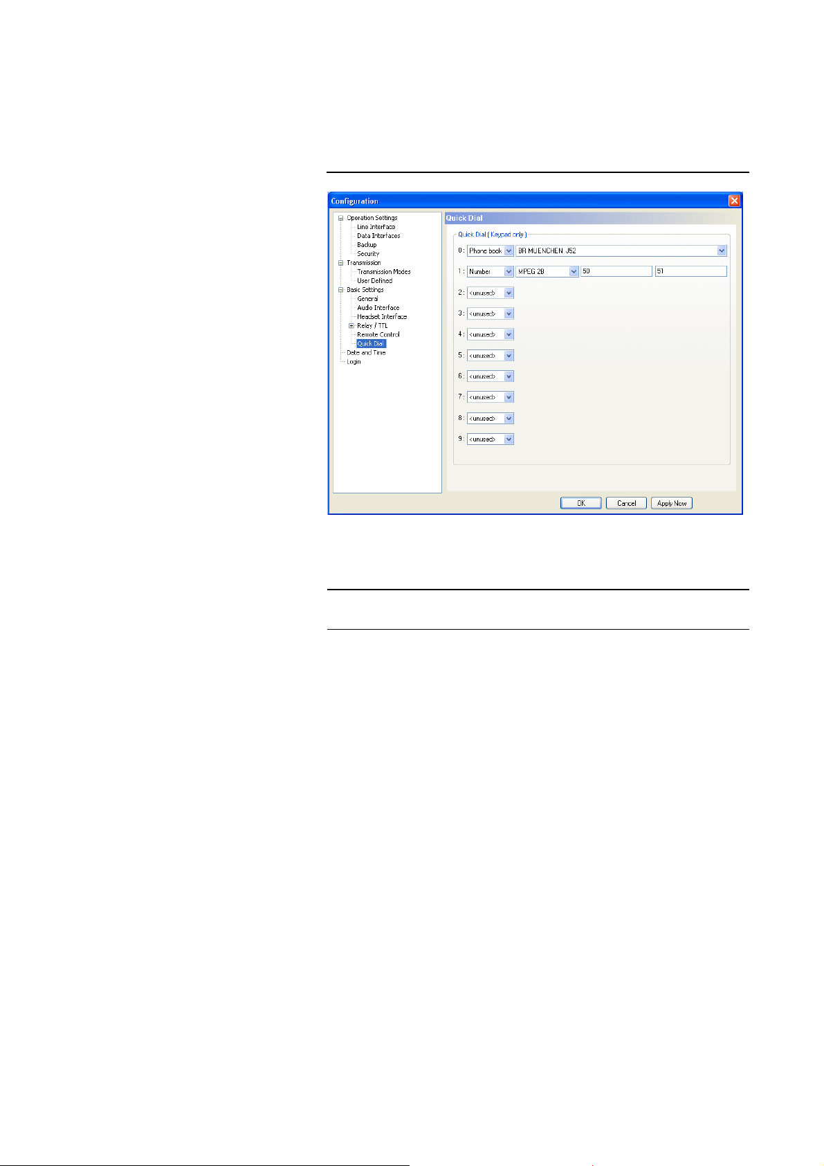
Windows PC Software
5.7.2.3.6 Quick Dial
The system allows you to call directly up to 10 partners via the numerical keys
0 ... 9 of the front display. The quick dial keys can be programmed via the
menu Quick Dial.
FIG. 51 QUICK DIAL
NOTE
Please assign an already existing Phone Book entry to a key or define a new
Number with a selected Transmission Mode (see Chapter 5.7.2.2.1, page 64).
The quick dial functionality can only be used on the system. The PC Software
has no quick dial keys.
PAGE 86
Page 87
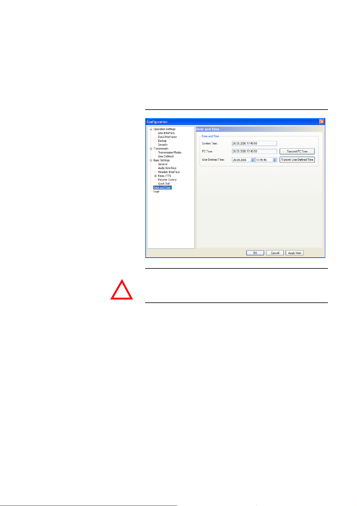
5.7.2.4 Date and Time
Via the dialogue Date and Time you can program the system date and time.
Via the button Transmit PC Time you can synchronise the system time with
your PC time.
The button Transmit User Defined Time allows you to set a different time.
This function is helpful, if you want to use the system later on e.g. in a different time zone.
FIG. 52 DATE AND TIME
Windows PC Software
ATTENTION During a power breakdown the integrated system clock is buffered by an in-
ternal battery
a
. The life time of a battery is typical ca. 7 years. The replace-
ment should only be done by the AVT Service.
!
a
Type: 3V Lithium Battery Renata CR1220
PAGE 87
Page 88
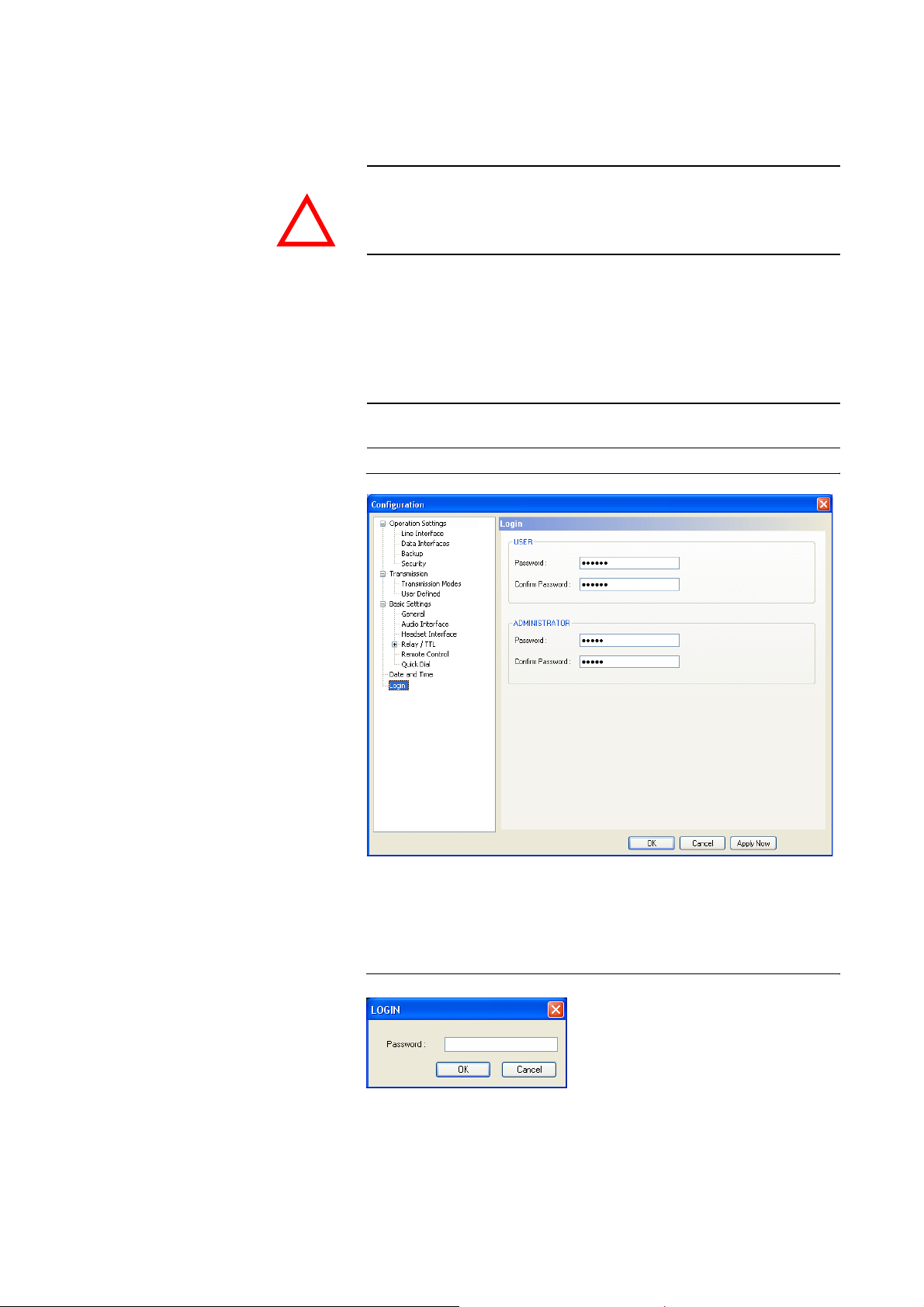
Windows PC Software
5.7.2.5 Login
ATTENTION The entered passwords are stored in the system. Take care in entering a pass-
To protect the system from reconfiguration, two password levels with different user rights are available
word. If you forgot your password, the system can only be unlocked by the
AVT Service.
!
•Under USER you can assign the User Password. For safety reasons the
password needs to be confirmed under Confirm Password.
•Under ADMINISTRATOR you can assign the Administrator Password.
For safety reasons the password needs to be confirmed under Confirm
Password.
NOTE
It is not differentiated between upper and lower case when a password is enterd.
FIG. 53 LOGIN
PAGE 88
As soon as you assigned a password, a Login window is automatically displayed when you click on a menu which is protected by the password. Please
enter the user or the administrator password there.
FIG. 54 PASSWORD LOGIN
The user and administrator rights are allocated in the following way:
(1) Only Administrator Password configured: Password is required for
changes in the configuration. Immediately available menus:
Page 89

Windows PC Software
– Configuration → Presets→ „Preset Name“
– Extras → System Monitor
(2) Only User Password configured: The password is always required. Af-
ter the password has been entered, all menus are available. Immediately available menus:
NOTE
– Extras
User and Administrator Password configured. A password is always
required. Immediately available menus:
– Extras
User Password is entered:
–Under Configuration → Configuration → Login only the USER
Password can be changed.
–With Configuration
Administrator Password is entered: All menus are available.
Please notice also the effect on the possibilities for configuration, if a password is assigned.
→
System Monitor
→
System Monitor
→
Presets the desired preset can be loaded.
PAGE 89
Page 90
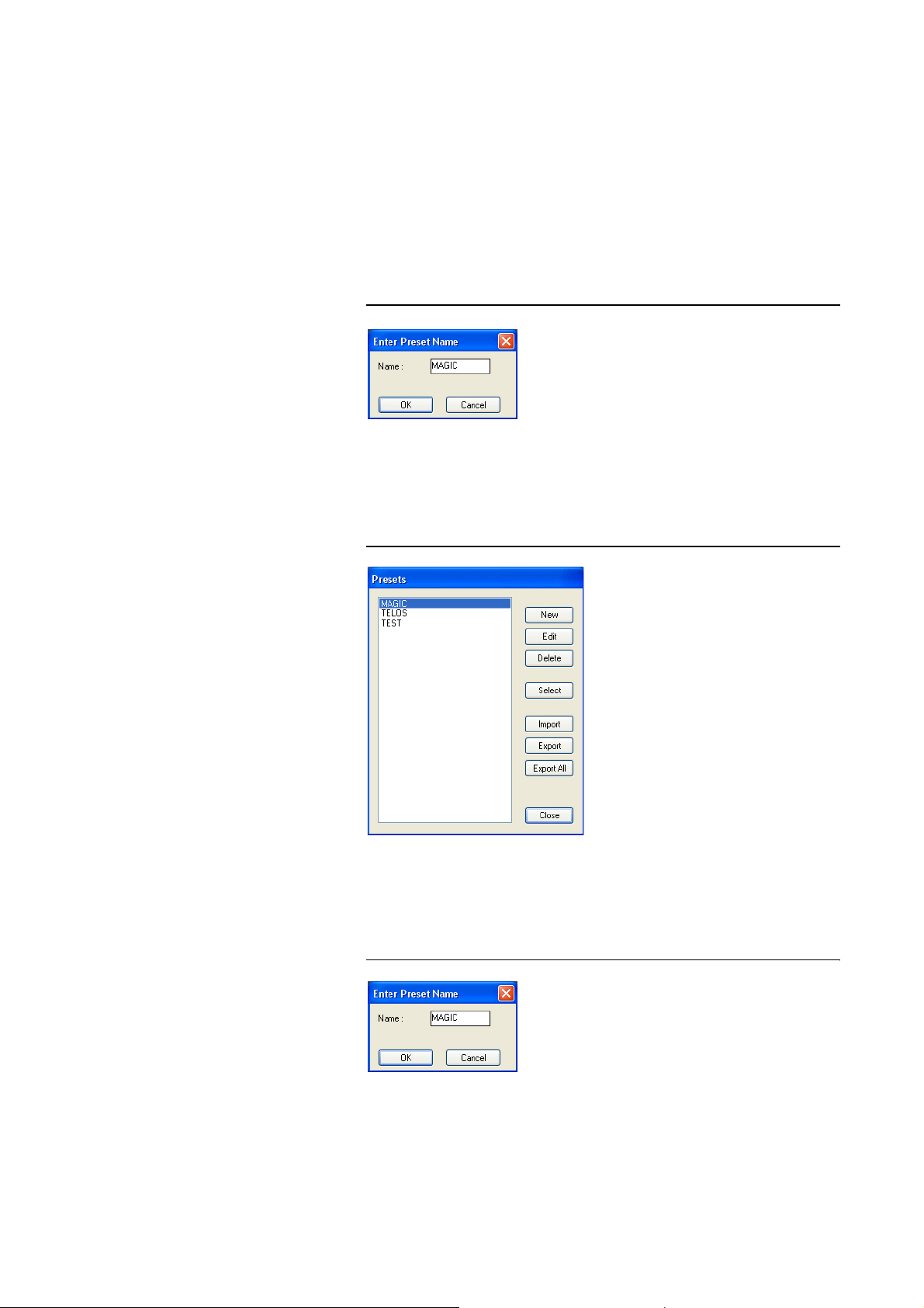
Windows PC Software
5.7.3 Submenu Presets
5.7.3.1 Save as ...
5.7.3.2 Manage Presets
Via Presets you can save, load and edit configuration presets.
Via the option Save as ..., the current configuration can be saved as Preset
under any name (max. 8 characters). Special characters and space characters
are not allowed. Please make sure that you use clear-cut names, otherwise an
error message is displayed asking you if you want to overwrite the already existing preset.
FIG. 55 SAVE PRESET
You can manage your Presets via the menu Configuration
Presets
→
→
Manage Presets.
FIG. 56 MANAGE PRESETS
In the list, all already created configuration presets are displayed.
With the New button, a new configuration can be created. The current configuration of the system is not changed or loaded. First enter a reasonable name.
PAGE 90
FIG. 57 CREATE NEW PRESET
Page 91
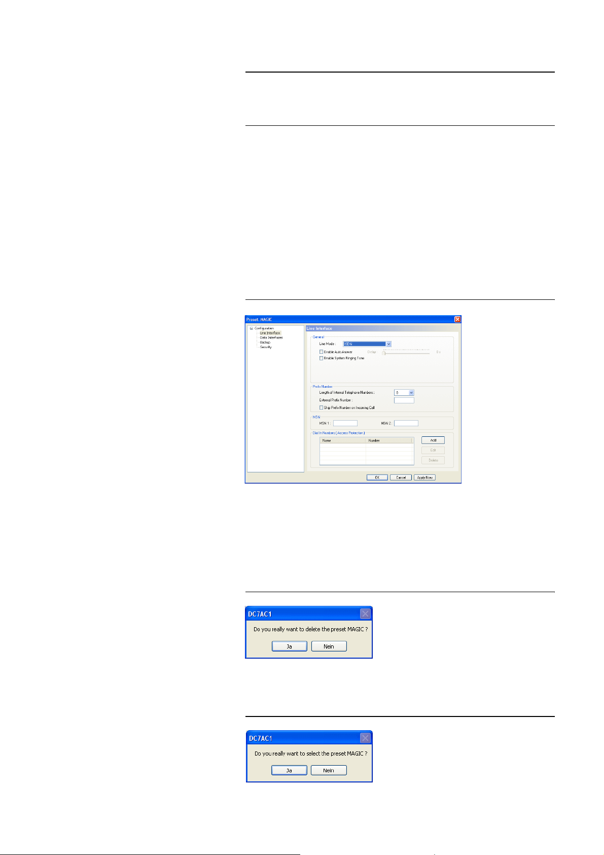
Windows PC Software
NOTE
The length of the name must not exceed 8 characters. Special characters and
space characters are not allowed. Please make sure that you use clear-cut
names, otherwise an error message is displayed asking you if you want to
overwrite the already existing preset.
Now, the configuration dialogue is opened to edit the Presets. The current
configuration is always displayed as basis of the Preset, which can be
adapted according to your requirements. The following settings can be saved
in a Preset:
– Line Interface (see page 52)
– Data Interfaces (see page 57)
– Backup (see page 58)
– Security (see page 62)
– Display of the Bit rates in the main window (see page 67)
FIG. 58 EDIT PRESET
The Edit button allows you to edit the configuration which is currently selected in the list. The current configuration of the system is not changed or
loaded.
With the Delete button you can delete the configuration which is currently selected. A confirmation is required.
FIG. 59 CONFIRMATION TO DELETE A PRESET
To activate a configuration selected from the list, please press the Select but-
ton. A confirmation is required.
FIG. 60 CONFIRMATION TO ACTIVATE A PRESET
PAGE 91
Page 92
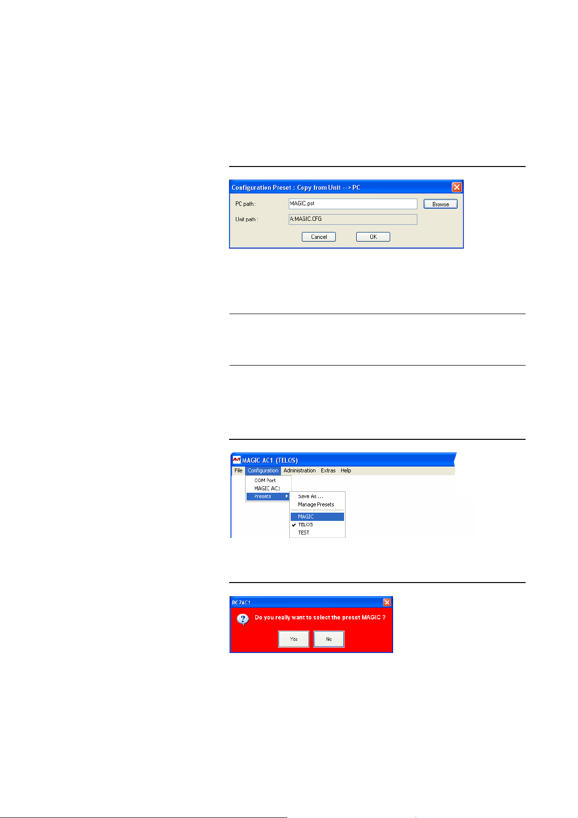
Windows PC Software
The Import button allows you to import a configuration preset form a data
carrier (disk, USB stick etc.). The file extension of a preset file is always ‘.pst‘.
After clicking on the Import button, the file browser is displayed via which
the desired file can be selected.
It is also possible to export configurations to a data carrier. The Export button
saves the configuration preset selected from the list as ‘.pst‘ file. After clicking
on the Export button, the file browser is displayed via which the desired storage location can be selected with Browse.
FIG. 61 EXPORT A PRESET
With Export All you can save all configurations displayed in the list in a directory of your choice. For each configuration, an individual file with the extension ‘.pst‘ is generated.
TIP
5.7.3.3 Activate a Preset
If you have to configure several systems in the same way, please save the
complete system configuration with File
(see CHAPTER 5.6). Please note that the telephone book is not saved with the
configuration.
All Presets are displayed under Configuration
Name“ and can be activated by simply clicking on them.
FIG. 62 ACTIVATE A PRESET
For safety reasons a confirmation is required.
FIG. 63 CONFIRMATION TO ACTIVATE A PRESET
→
System Settings → Export
→
Presets → „Preset
PAGE 92
Page 93
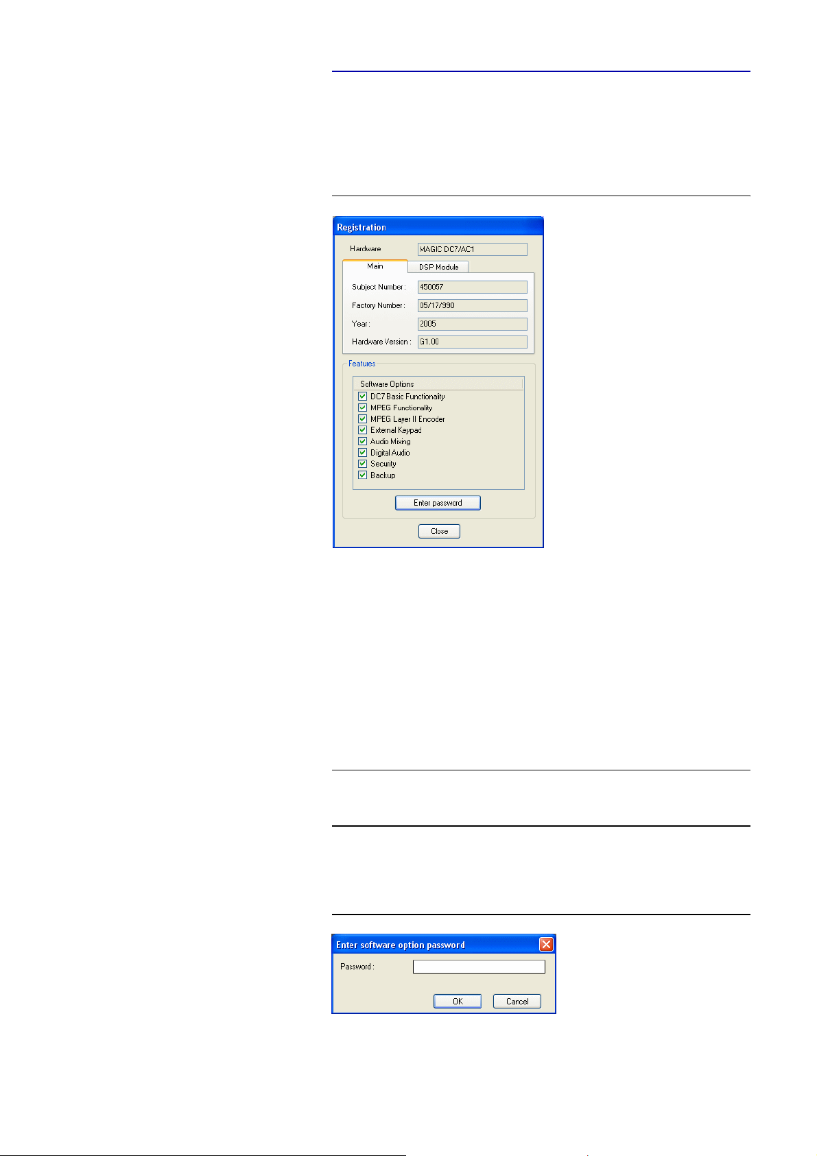
5.8 Menu Administration
5.8.1 Submenu Registration
Via the submenu Registration you can check the activated Firmware Options.
FIG. 64 REGISTRATION
Windows PC Software
NOTE
Under Hardware, the system type (here: MAGIC DC7/AC1) is displayed. On
the Main tab, all relevant features for identification like Subject Number,
Factory Number, Year of production and Hardware Version are displayed.
Under the DSP Module tab you find the features for the DSP Module (only
MAGIC AC1).
Under Features all available Software Options are listed.
Upgrade of Firmware Options
For an Upgrade, we need the serial number (Factory Number) of the system.
Please read out the serial number always from the Registration, since the serial number on the system label could be different.
To activate further Firmware Options at a later time, please enter the password, which you received from us, in the dialogue which opens when you
click on the button Enter Password.
FIG. 65 PASSWORD ENTRY
PAGE 93
Page 94
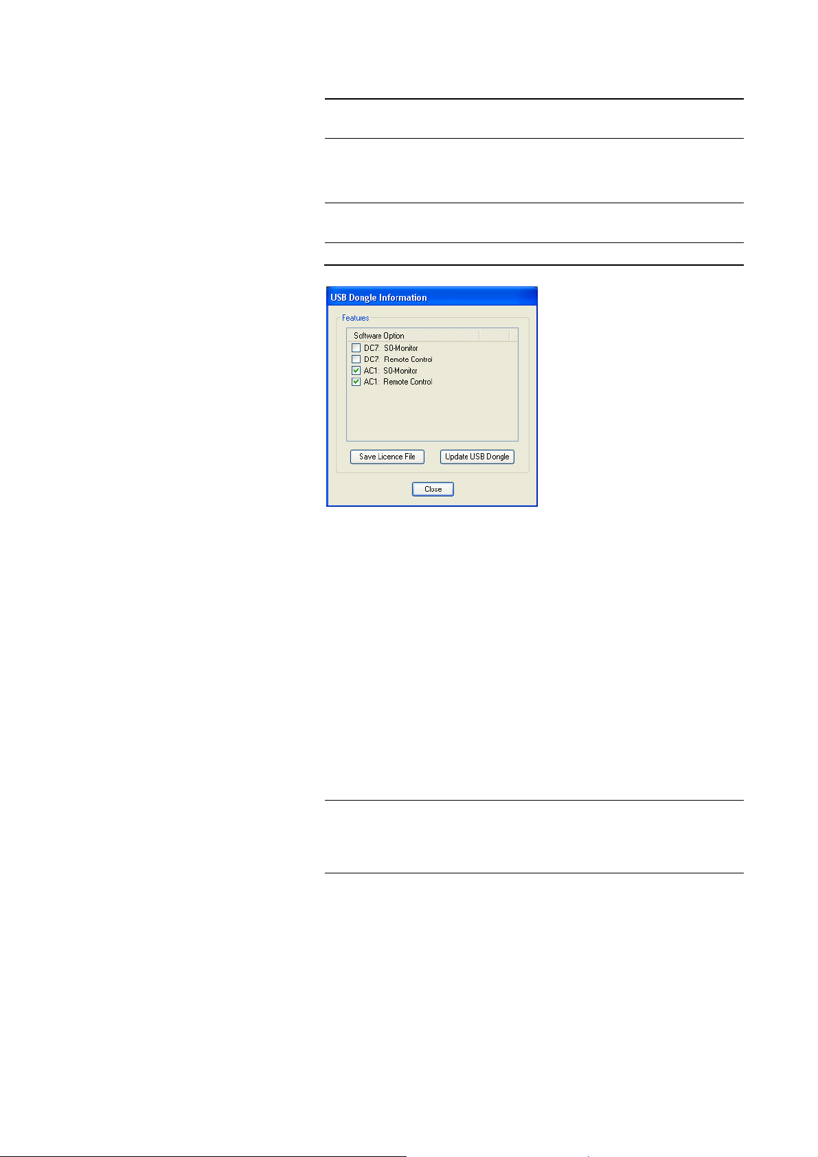
Windows PC Software
5.8.2 Submenu USB Dongle Information
NOTE
NOTE
The submenu USB Dongle Information is only displayed if the USB-Dongle
for fee-based options is connected to the PC.
In the window USB Dongle Information you see the PC Software Options
which are enabled for your system.
Please consider that we differentiate between PC Software Options (e.g. S
Monitor) and Firmware Options (e.g. Mixer Tools).
FIG. 66 USB DONGLE INFORMATION
0
NOTE
Upgrade of PC Software Options
If you want to activate further PC Options at a later time, please press the button Save Licence File, whereby the current licence key is stored in a file.
The standard name is LicenceInfo.c2v, the storage location can be chosen by
yourself.
With the file LicenceInfo.c2v - which you send us e.g. by email to sup-
[email protected] - we can activate the Upgrade.
Afterwards, we send you the file LicenceUpdate.v2c, which you can load to
your system by clicking on the Update USB Dongle button.
Now the new function is available.
In Fig. 66 you can see that in a USB-Dongle several system versions can be
managed. For example, if you want to control MAGIC DC7 and MAGIC AC1
systems remotely, it is possible with one USB-Dongle, if the options are activated for it.
PAGE 94
Page 95

5.8.3 Submenu Remote Control
Windows PC Software
NOTE
The submenu Remote Control is only available, if the fee-based Option: Remote Control Software (see CHAPTER 8) is enabled and the USB dongle is
plugged in.
Further details concerning the function Remote Control can be found under
CHAPTER 8, Page 117.
PAGE 95
Page 96
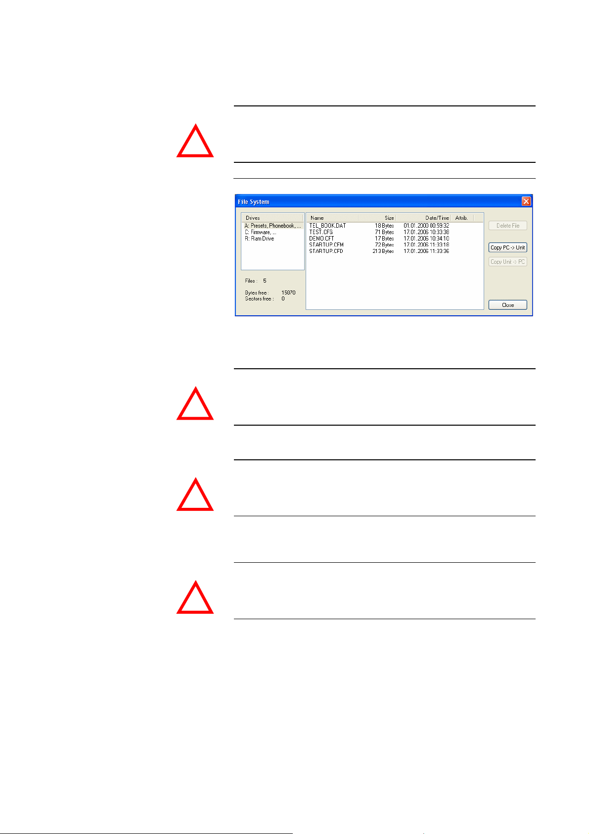
Windows PC Software
5.8.4 Submenu File System
ATTENTION Please do not carry out any actions under File System unless our support
By selecting the submenu File System the file directory of the system (similar
to the harddisk of a PC) is displayed.
asked you to. All user import/export functions can be found under the menu
File (see CHAPTER 5.6).
!
FIG. 67 SUBMENU FILE SYSTEM
Via the button Delete File the currently selected file is deleted from the system.
ATTENTION Do not delete a file unless our service told you to delete the file. Otherwise a
malfunction of the system can occur.
!
The Copy PC -> Unit button allows you to copy a file from a PC to the system.
ATTENTION Please use only the function Firmware Download (see CHAPTER 5.8.6) re-
spectively the import functions in the menu File (see CHAPTER 5.8.4) to
copy files on the system.
!
The Copy Unit -> PC button allows you to copy a file from the system to the
connected PC.
ATTENTION Please use only the export functions under the menu File (see CHAPTER 5.6),
to copy files to a PC.
!
PAGE 96
Page 97
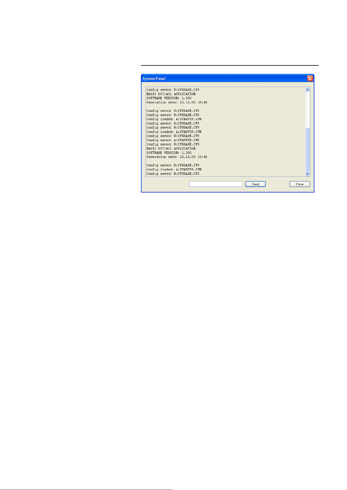
5.8.5 Submenu System Panel
The System Panel is only for service purposes. Please only enter commands
in the prompt, if our support asked you to do so.
FIG. 68 SUBMENU SYSTEM PANEL
Windows PC Software
PAGE 97
Page 98
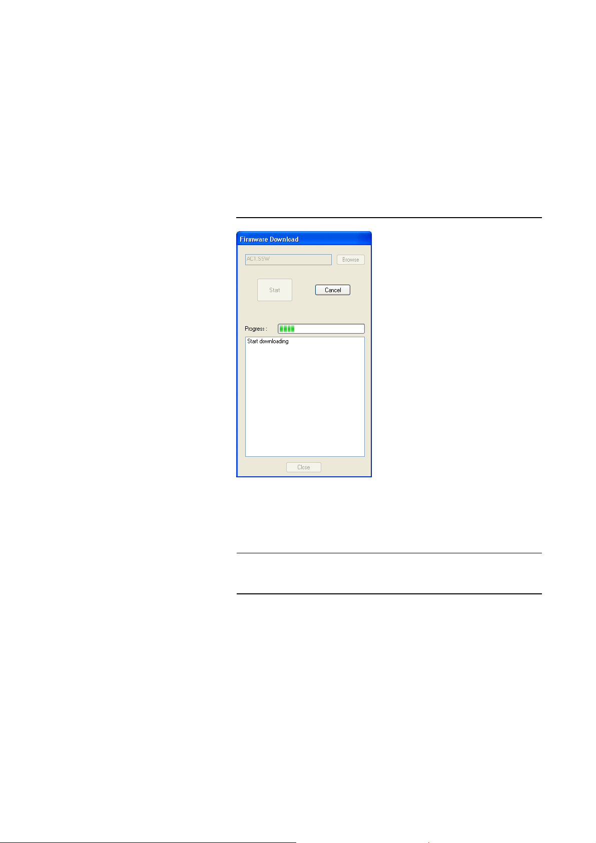
Windows PC Software
5.8.6 Submenu Firmware Download
The Firmware required for the MAGIC DC7/AC1 system is always included
in the PC software. Via the Firmeware Download the firmware can be com-
fortably loaded on the system.
Via the Browse button you select the firmware file. The file is always stored
in the directory in which you installed the MAGIC DC7/AC1 application. The
standard installation directory is:
C:\Programme\MAGIC DC7 & AC1
The name of the firmware file is „ac1.ssw“.
FIG. 69 FIRMWARE DOWNLOAD
NOTE
Please press the Start button to load the firmware on your system. The Progress bar shows the status of the download. After about three minutes the
download will be finished. If the download had been successful, a message is
displayed. After a confirmation the system executes a reset.
If a download had been faulty, you can simply switch off the unit and then
switch it on again. The new software is only written in the flash memory, if a
download had been successful. Otherwise the old firmware is maintained.
PAGE 98
Page 99
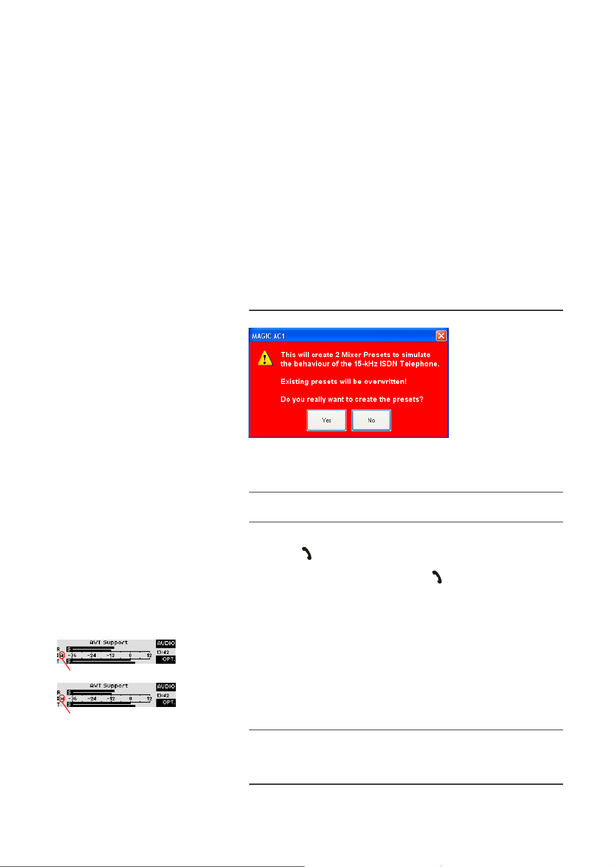
Windows PC Software
5.8.7 Submenu Create 15-kHz Telephone Mixer Presets
The function Create 15-kHz Telephone Mixer Presets allows you to work
with the MAGIC DC7/AC1 almost as with the 15-kHz ISDN Telephone respectively, the old PKI 7-kHz ISDN Telephone. These systems offered a simple
switching between the handset and the Audio interface with only one keystroke. First, the user could talk to his partner via the telephone handset and
then start an external Audio transmission by pressing the Audio button at the
telephone.
This functionality is also offered by MAGIC DC7/AC1 if two Mixer Presets
(see CHAPTER , page 44) are created. One preset is used to switch to a handset or headset and a second preset is used to switch to the Audio inputs/outputs. The presets can be adjusted according to your requirements later on.
First, please create the two presets by selecting the submenu Create 15-kHz
Telephone Mixer Presets.
Since already existing mixer presets are overwritten by this action, a warning
is displayed.
FIG. 70 WARNING WHEN MIXER PRESETS ARE CREATED
Mixer Preset AUDIO active
Mixer Preset HANDSET active
TIP
NOTE
If you agree to create the presets (YES), the Mixer Presets Handset and Audio
are created.
The settings of both Mixer Presets can be controlled and changed via the submenu Extras
The switching between the two Mixer Presets during a connection is made by
pressing the -button.
Please assign the two Mixer Presets to the -button, by clicking on them
(Handset and Audio) under Configuration
→
Basic Settings → General → Toggle Mixer Presets on Call/Accept
Button.
In the front display of the system, the first character of the currently activated
mixer preset is displayed.
Please note that depending on the microphone you use, in certain cases you
must activate the phantom power and the limiter via Configuration
GIC AC1 (MAGIC DC7)
CHAPTER 5.7.2.3.3)
→
Audio Mixer.
.
→
MAGIC AC1 (MAGIC DC7)
→
→
Basic Settings → Headset Interface (see
MA-
PAGE 99
Page 100

Windows PC Software
5.8.8 Submenu Set Factory Settings
Via the submenu Factory Settings all settings are reset to the factory settings.
For safety reasons a confirmation is required.
FIG. 71 CONFIRMATION TO SET FACTORY SETTINGS
NOTE
The telephone book, Presets, Transmission Modes and Mixer settings are not
deleted.
PAGE 100
 Loading...