

Page 1

MAGIC AE1 DAB+
DAB+ Audio Encoder
Hardware/Software Manual
Page 2

.
Page 3

M A G I C A E 1 D A B +
D A B + A u d i o E n c o d e r
H a r d w a r e / S o f t w a r e M a n u a l
Page 4

Page 5

A publication of:
AVT Audio Video Technologies GmbH
Nordostpark 12
D-90411 Nuernberg
Germany
Phone: +49 911 5271-0
Fax: +49 911 5271-100
Support: [email protected]
Printed in Germany, October 2016
AVT Audio Video Technologies GmbH
All rights reserved. Reproduction in
whole or in parts is prohibited without the
written consent of AVT Audio Video
Technologies GmbH.
Subject to changes.
Release date: (10.16)
Page 6

.
Page 7

C o n t e n t
C o n t e n t
INTRODUCTION 11
SAFETY 13
Introduction 13
General safety requirements 13
1 CONSTRUCTION 15
2 SYSTEM DESCRIPTION 17
2.1 Functionality 17
3 PUTTING THE SYSTEM INTO OPERATION 19
3.1 Mounting 19
3.2 Connection to the mains voltage 19
3.3 Earthing of the system 19
3.4 Operational elements on the front side 20
3.5 Wiring diagram 21
4 OPERATION VIA DISPLAY AND KEYPAD 23
4.1 Standard functions 23
4.2 Basic configurations 24
4.2.1 Selecting the menu language 24
4.2.2 Configuration of the LAN Interface 24
4.2.3 Setting the Audio interface: Analogue or digital 25
4.2.4 Configuring the DAB+ parameters 26
4.3 The Status Display - Operation during a connection 27
4.4 Working with Presets 28
5 WINDOWS PC SOFTWARE 29
5.1 Hardware requirements 29
5.2 Installing the Windows PC Software 29
5.3 MAGIC AE1 DAB+ main window 31
5.3.1 Operating elements 32
5.4 Menu file 33
5.4.1 Operation Settings Presets 33
5.4.2 System Settings 33
Page 8

C o n t e n t
5.4.3 Submenu Exit 33
5.5 Menu Configuration 34
5.5.1 Submenu Control Interface 34
5.5.2 Submenu MAGIC AE1 DAB+ 40
5.5.2.1 Operation Settings 40
5.5.2.1.1 Line interface 40
5.5.2.1.2 MUXENC Parameters 42
5.5.2.1.3 Encoder Parameters 44
5.5.2.1.4 PAD Interface 46
5.5.2.1.5 UECP Parameters 48
5.5.2.1.6 Relay/TTL 50
5.5.2.2 System Settings 56
5.5.2.2.1 General 56
5.5.2.2.2 Audio Interface 58
5.5.2.2.3 LAN interface 60
5.5.2.2.4 NTP 62
5.5.2.2.5 SNMP Parameters 63
5.5.2.2.6 VLAN 64
5.5.2.2.7 Date and Time 65
5.5.2.3 Login 66
5.5.3 Submenu Presets 68
5.5.3.1 Manage Presets 68
5.5.3.2 Activation of a Preset 69
5.5.4 Submenu Local Settings 70
5.6 Menu Administration 71
5.6.1 Submenu Registration 71
5.6.2 Submenu File System 73
5.6.3 Submenu System Panel 74
5.6.4 Submenu Firmware Download 75
5.6.5 Submenu LAN2 Adapter Download 76
5.6.6 Submenu Set Factory Settings 78
5.7 Menu Extras 79
5.7.1 Submenu System Monitor 79
5.7.2 Submenu Locate MAGIC AE1 DAB 83
5.7.3 Sync System Time With PC Time 83
5.8 Menu Help 84
5.8.1 Submenu About MAGIC AE1 DAB+ 84
A1 MENU STRUCTURE 85
A1.1 System Settings 86
A1.2 Operation Settings 87
A1.3 Presets 88
A1.4 Status Information 89
A1.5 Login 90
Page 9

C o n t e n t
A2 INTERFACES 91
A2.1 Control and data interfaces 92
A2.1.1 DATA/PAD interface 92
A2.2 ISDN interface 93
A2.3 LAN interfaces 93
A2.4 X.21 interface 94
A2.5 TTL/RELAY interface 95
A2.6 Audio interfaces 96
A2.6.1 Analogue Audio interface 96
A2.6.2 Digital AES/EBU Audio interface 96
A2.6.3 HEADSET/MIC interface 97
A3 TECHNICAL DATA 99
A4 GENERAL 101
A4.1 Ordering numbers 101
A4.2 Scope of delivery 101
A4.3 Declaration of Conformity 101
A5 SERVICE INFORMATION 103
A5.1 Software Updates 103
A5.2 Support 103
A5.3 Repairs 103
INDEX 105
DECLARATION OF CONFORMITY 109
Page 10

C o n t e n t
Page 11

PAG E 1 1
I n t r o d u c t i o n
I N T R O D U C T I O N
The system MAGIC AE1 DAB+ is implemented as DAB+ Audio Encoder and
has analogue and digital AES/EBU audio interfaces. Each system has its own
monitoring decoder inside which allows you to check the system’s functionality and to evaluate the audio quality.
The HE-AAC-V2 DAB+ audio encoder is an implementation of the FhG
(Fraunhofer Gesellschaft) in Erlangen.
The configuration of the system can be carried out via the Windows PC Software included in delivery or via the front keypad and display of the unit.
English
Deutsch
Menu
Select
Back
System Settings
Language
Ok
Save settings?
Yes
No
Operation Settings
Select
Mode
Audio
Audio Settings
Audio Settings
Audio input
Audio output
Analogue
Digital
No system
Delete
Opt.
Line
Search
Edit
Display
Presets
Load
New
Save
Delete Preset
Signal Processing
Keypad 9600, none
Status information
Login
Shift
Mon.
Cod
Org
DAB+ Parameter
Audio Data Rate
Sampling Frequency
Page 12

PAG E 1 2
I n t r o d u c t i o n
Mono Mode
Mono L+R/2
Mono Left
Mono Right
Mode
Mono
Mono + SBR
Stereo
Stereo + SBR
Parametric Stereo + SBR
PAD Interface
Activate PAD
Active
Baudrate
38400
57600
115200
Load Factory Settings
Page 13

PAG E 1 3
S a f e t y
S A F E T Y
Introduction
The unit described has been designed to the latest technical parameters and
complies with all current national and international safety requirements. It
operates on a high level of reliability because of long-term experience in development and constant and strict quality control in our company.
In normal operation the unit is safe.
However, some potential sources of danger for person, material and optimal
operation remain - especially if daily routine and technical errors coincide.
This manual therefore contains basic safety instructions that must be observed during configuration and operation. It is essential that the user reads
this manual before the system is used and that a current version of the manual
is always kept close to the equipment.
General safety requirements
To keep the technically unavoidable residual risk to a minimum, it is absolutely necessary to observe the following rules:
– Transport, storage and operation of the unit must be under the permissible
conditions only.
– Installation, configuration and disassembly must be carried out only by
trained personnel on the basis of the respective manual.
– The unit must be operated by competent and authorised users only.
– The unit must be operated in good working order only.
– Any conversions or alterations to the unit or to parts of the unit (including
software) must be carried out by trained personnel authorised by the manufacturer. Any conversions or alterations carried out by other persons lead
to a complete exemption of liability.
– Only specially qualified personnel is authorised to remove or override
safety measures, and to carry out the maintenance of the system.
– External software is used at one’s one risk. Use of external software can af-
fect the operation of the system.
– Use only tested and virus-free data carriers.
Page 14

PAG E 1 4
S i c h e r h e i t
Text Conventions
In this manual the following conventions are used as text markers:
Accentuation: Product names or important terms
: Labelling on the front display of the system
PC Text: Labelling in the PC Software
TIP
The symbol TIP marks information which facilitates the operation of the system in its daily use.
NOTE
The symbol NOTE marks general notes to observe.
ATTENTION The symbol ATTENTION marks very important advice that is absolutely to
observe. In case of non-observance disfunctions and even system errors are
possible.
!
Page 15
PAG E 1 5
C o n s t r u c t i o n
1 C O N S T R U C T I O N
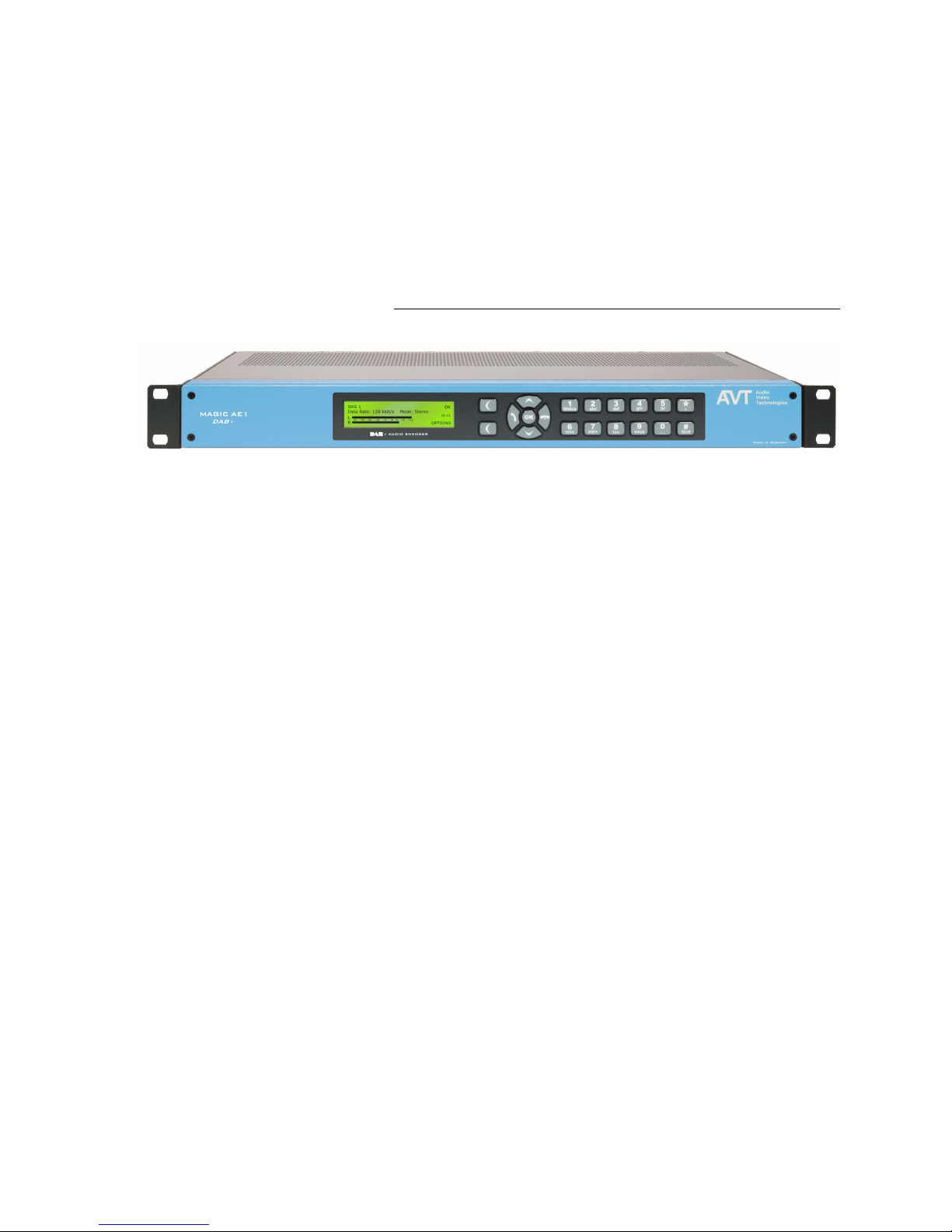
The functions of the MAGIC AE1 DAB+ are implemented in a single unit. The
system is equipped with a module for HE-AAC-V2 coding. The system is designed for mounting in a 19" rack (1 U). 19“ brackets are part of the delivery.
FIG. 1 FRONT VIEW: MAGIC AE1 DAB+ AUDIO ENCODER
Page 16

PAG E 1 6
C o n s t r u c t i o n
Page 17
PAG E 1 7
S y s t e m D e s c r i p t i o n
2 S Y S T E M D E S C R I P T I O N
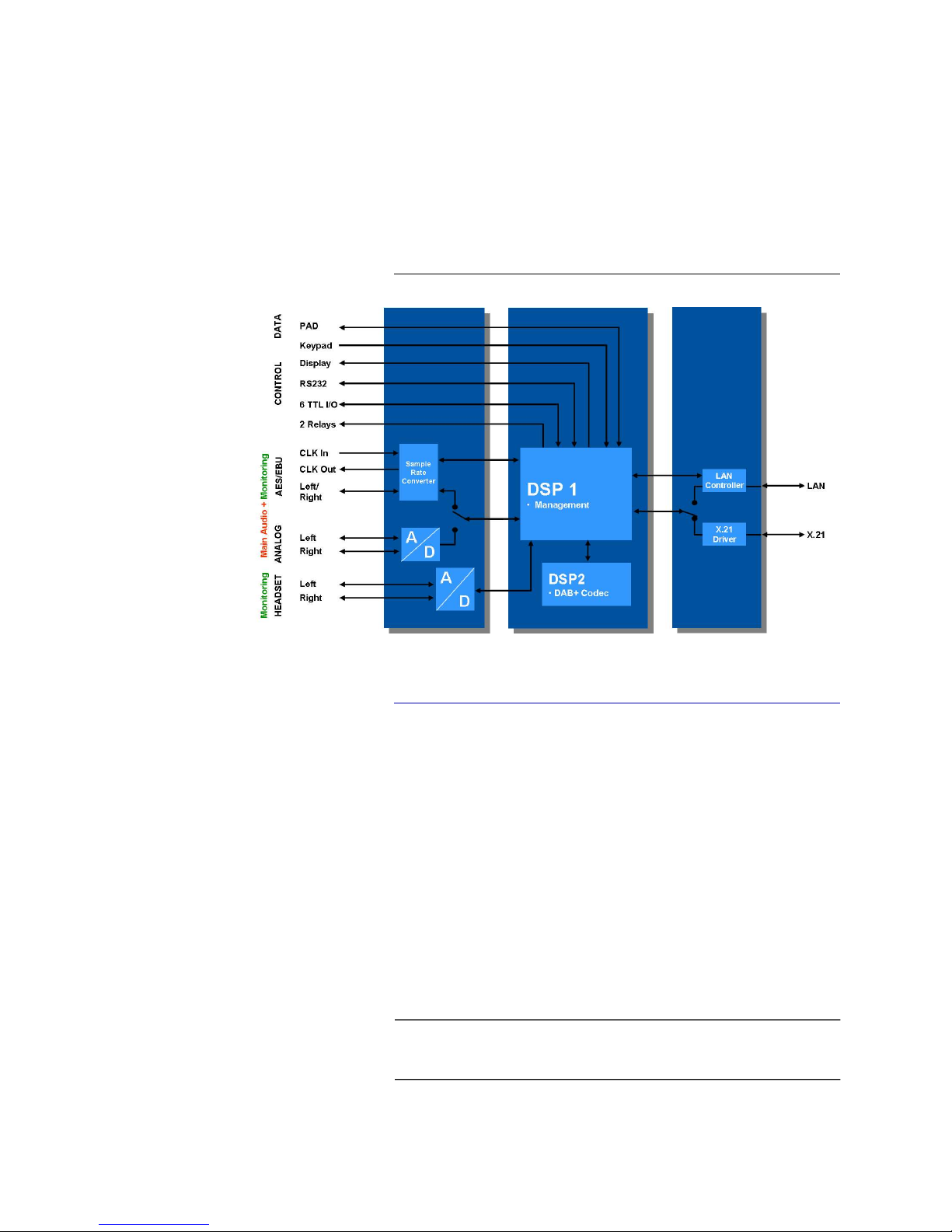
The functional elements of the system are pictured in Fig. 2.
FIG. 2 FUNCTIONAL ELEMENTS OF MAGIC AE1 DAB+ AUDIO ENCODER
2.1 Functionality
The MAGIC AE1 DAB+ Audio Encoder is equipped with a LAN interface for
a direct connection to the AVT MAGIC DAB MUX Multiplexer based on the
Fraunhofer Content Server® technology or to other Ensemble Multiplexers
supporting EDI. For the connection to Fraunhofer Multiplexers, the FhG
MUXENC protocol is optionally available.
NTP is used for the synchronisation of the systems’ clocks when the Encoder
is connected to a Multiplexer. The communication between the Encoder and
the Multiplexer is realised via the EDI protocol or via the FhG MUXENC pro-
tocol.
Additionally, the MAGIC AE1 DAB+ system incorporates an X.21 interface
for a connection to all standard Ensemble Multiplexers (e.g. R&S DM-001)
which do not provide a LAN interface. The X.21 clock is derived from the Ensemble Multiplexer clock.
The complete signal processing is taken over by two digital signal processors.
In this way the following functions are realised:
NOTE
The MAGIC AE1 DAB+ Audio Encoder Firmware and PC Software supports
the X.21 operating mode until software version 2.320. With later software re-
leases only the LAN operating mode is possible.
Page 18

PAG E 1 8
S y s t e m D e s c r i p t i o n
DSP1:
– Digital audio router
– Signalling management
– Control of the complete system (Keypad, display, relays, TTL, RS232)
– PAD multiplexer
DSP2:
– HE-AAC-V2 DAB+ Encoder and Decoder
Via the main audio channel the high quality Stereo or Mono audio signal is
inserted analogue or digitally. If the digital AES/EBU audio interface is used,
a Sample Rate Converter is available for automatic clock synchronisation between network and audio source. For external clocking a clock input and a
clock output are available.
The audio outputs can be used for monitoring purposes. The encoded signal
is looped continuously to the HE-AAC-V2 decoder. The decoded audio signal
is available as analogue or digital audio output signal. As second audio monitoring interface a headphone interface is available.
All relevant basic settings can be made the front keypad and the illuminated
display.
Configuration and control is especially comfortable with the MAGIC AE1
DAB+ Windows PC Software which is included in delivery and which communicates with the system via the RS232 interface or the LAN interface. Via
the MAGIC AE1 DAB+ LAN Software up to 60 systems can be monitored and
selected for control.
Six programmable TTL contacts can be used for external signalling. Two re-
lays are available for status indication.
Page 19

PAG E 1 9
P u t t i n g t h e s y s t e m i n t o o p e r a t i o n
3 P U T T I N G T H E S Y S T E M I N T O O P E R A T I O N
3.1 Mounting
With its dimensions (W H D) of 431 mm 44,5 mm (1 U) 250 mm the
MAGIC AE1 DAB+ system can be used either as desktop device or mounted
in 19 inch racks. Corresponding 19“ mounting brackets are included in delivery.
When mounting the unit please keep in mind that the bending radius of the
cables is always greater than the minimum allowed value.
When the MAGIC AE1 DAB+ audio encoder is installed, please make sure
that there is sufficient ventilation: It is recommended to keep a spacing of ca.
3 cm from the openings. In general, the ambient temperature of the system
should be within the range of +5C and +45C. These thresholds are especially to observe if the system is inserted in a rack. The system works without
ventilation.
During operation air humidity must range between 5% and 85%.
3.2 Connection to the mains voltage
The system can be operated with mains voltages in the range from 90 V to
253 V. The frequency can vary from 45 Hz to 65 Hz. The maximum power
consumption is 15W (typically 12W).
After plugging the mains connector and switching on the system boots within
a few seconds. In stand-by mode the MAGIC AE1 DAB+ logo is shown on the
display.
3.3 Earthing of the system
For EMC reasons an earthing via the earthing screw of the system is recommended.
TIP
The system temperature can be indicated on the display (
(see CHAPTER A1.4, Page 89))
ATTENTION Incorrect ambient temperature and humidity can cause functional defi-
ciencies.
Operation outside the threshold values indicated above leads to a loss of warranty claim.
ATTENTION Earthing
A lacking earthing can cause functional deficiencies within the unit.
!
!
Page 20
PAG E 2 0
P u t t i n g t h e s y s t e m i n t o o p e r a t i o n
3.4 Operational elements on the front side
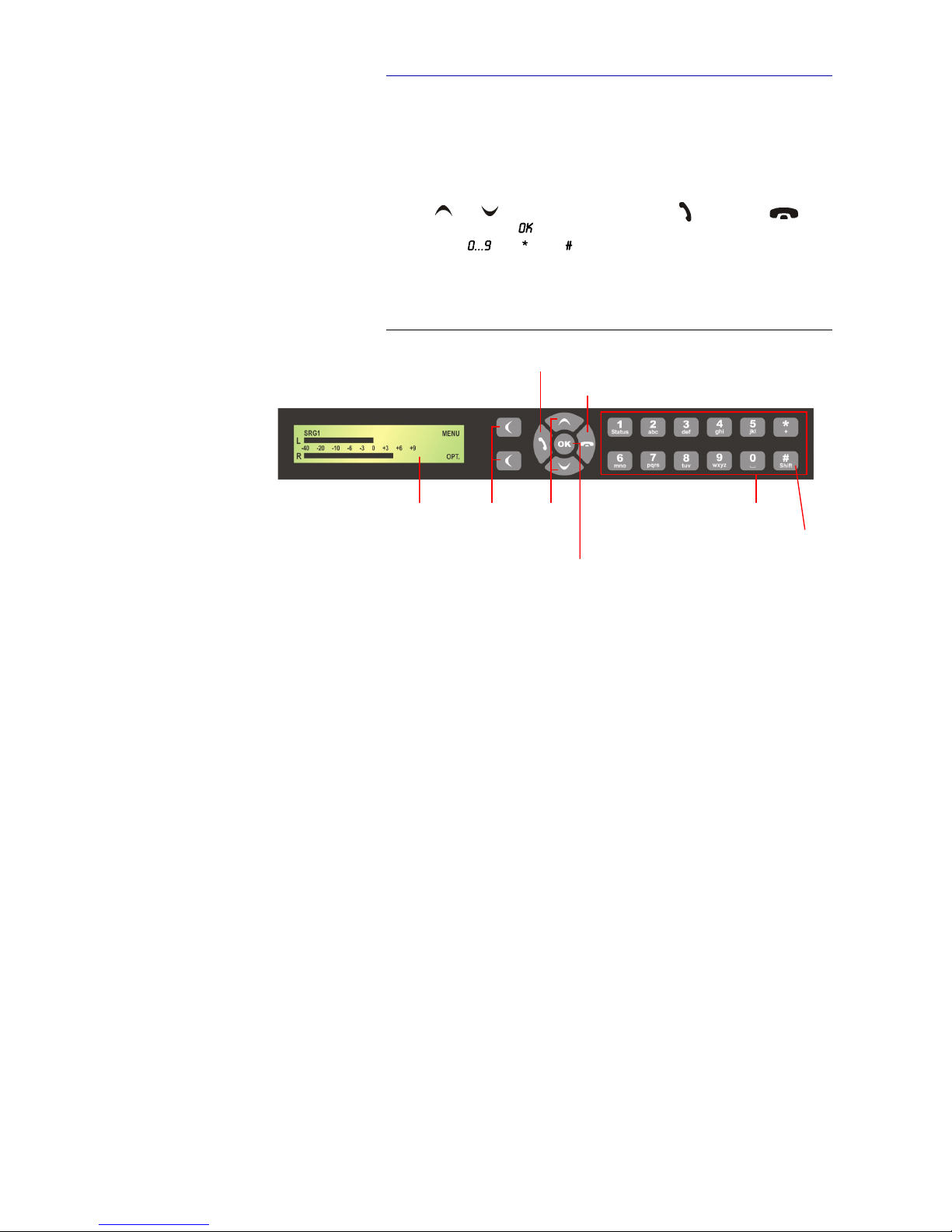
The system has an illuminated graphical display with a resolution of 160 x 32
Pixels and 19 operating buttons.
On the right next to the display there are two softkeys whose current functions are indicated on the display. In the middle there are two buttons for navigation ( and ), two buttons for establishing ( )/dropping ( ) connections as well as an button. The numerical pad supports in addition to
the numerics the ’ ’ and ’ ’ key. For text entries the numerical pad can
also be used as normal keypad.
The operation is similar to standard mobile telephones.
FIG. 3 OPERATIONAL ELEMENTS ON THE FRONT SIDE
Softkeys N avigation
buttons/
Est abli sh c onne ction
Drop c onn ection/
Main m enu
Keypad for
text entry
Displa y
shi ft
Confir m entry
Gra phic al
display
Status wi ndo w
Hea dpho ne
Level
Page 21
PAG E 2 1
P u t t i n g t h e s y s t e m i n t o o p e r a t i o n
3.5 Wiring diagram
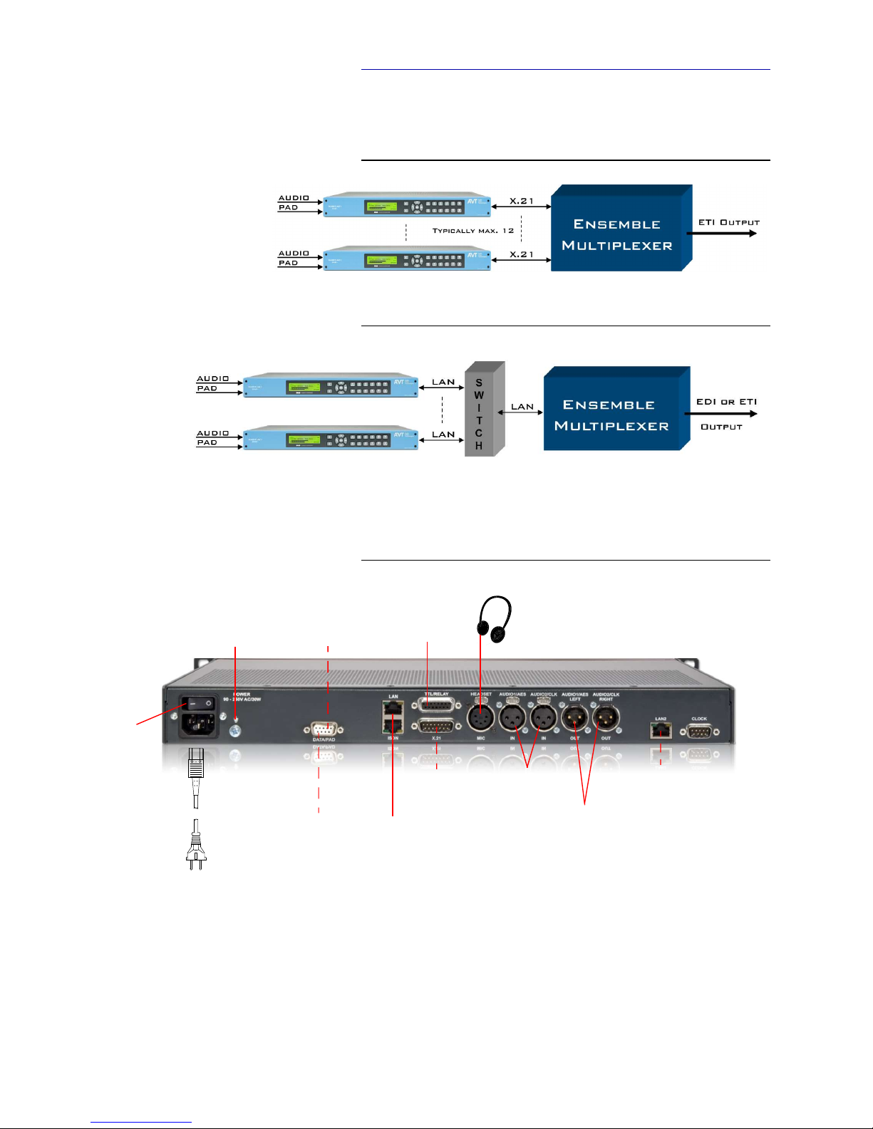
The figure below show the typical wiring diagrams of a DAB+ system depending on the interface in use - X.21 or LAN.
FIG. 4 WIRING DIAGRAM USING THE X.21 INTERFACE
FIG. 5 WIRING DIAGRAM USING THE LAN INTERFACE
The standard interfacing of the system is shown Fig. 6.
FIG. 6 WIRING & CONNECTION DIAGRAM
Mains
RS2 32
PC
RS232
PAD
X.2 1
Ensemble
Audio Input
Analogue/
Digita l
Audio Monitoring
Analogue/ Digital
Aud io Mon ito rin g
He adphone
Ear thin g
Pow er
Switch
Pow er
LAN
Mul tiplexer
Opt iona l 2nd
LAN int erfa ce
(PC , PAD
or SNMP)
TTL /RE LAY S
PAD
PC
MAGIC MUX
SNMP
NTP
Page 22

PAG E 2 2
P u t t i n g t h e s y s t e m i n t o o p e r a t i o n
Page 23

PAG E 2 3
O p e r a t i o n v i a D i s p l a y a n d K e y p a d
4 O P E R A T I O N V I A D I S P L A Y A N D K E Y P A D
In this chapter a few basic settings which can be made on the MAGIC AE1
DAB+ front keypad and display are explained. An overview of the menu
structure you will find in the annex under CHAPTER A1.
Of course, all configurations can also be comfortably made via the MAGIC
AE1 DAB+ Software included in delivery.
4.1 Standard functions
Keypad lock
To avoid that keys are pressed accidentally you can enable a keypad lock. For
activation please press the key followed by the (star) button. If the keypad lock is enabled the display illumination is turned off immediately.
The keypad lock is deactivated by entering the key sequence a second
time.
Softkey Menu
Using the softkey you can change all parameters of the system at any
time. The menu structure is given in CHAPTER A1.1 ... CHAPTER A1.5 (see
Page 86).
Reading out the factory number
When contacting our support or for the activation of fee-based software upgrade, you might need the factory number of the system.
For this please use the softkey and go to using the
cursor keys and . Press and go to again using the cursor
keys. Press and you will see the displayed.
NOTE
For the details of most functions, please have a look at the PC Software description from CHAPTER 5.
Page 24
PAG E 2 4
O p e r a t i o n v i a D i s p l a y a n d K e y p a d
4.2 Basic configurations
In the following some specific basic configurations of MAGIC AE1 DAB+ are
described in detail.
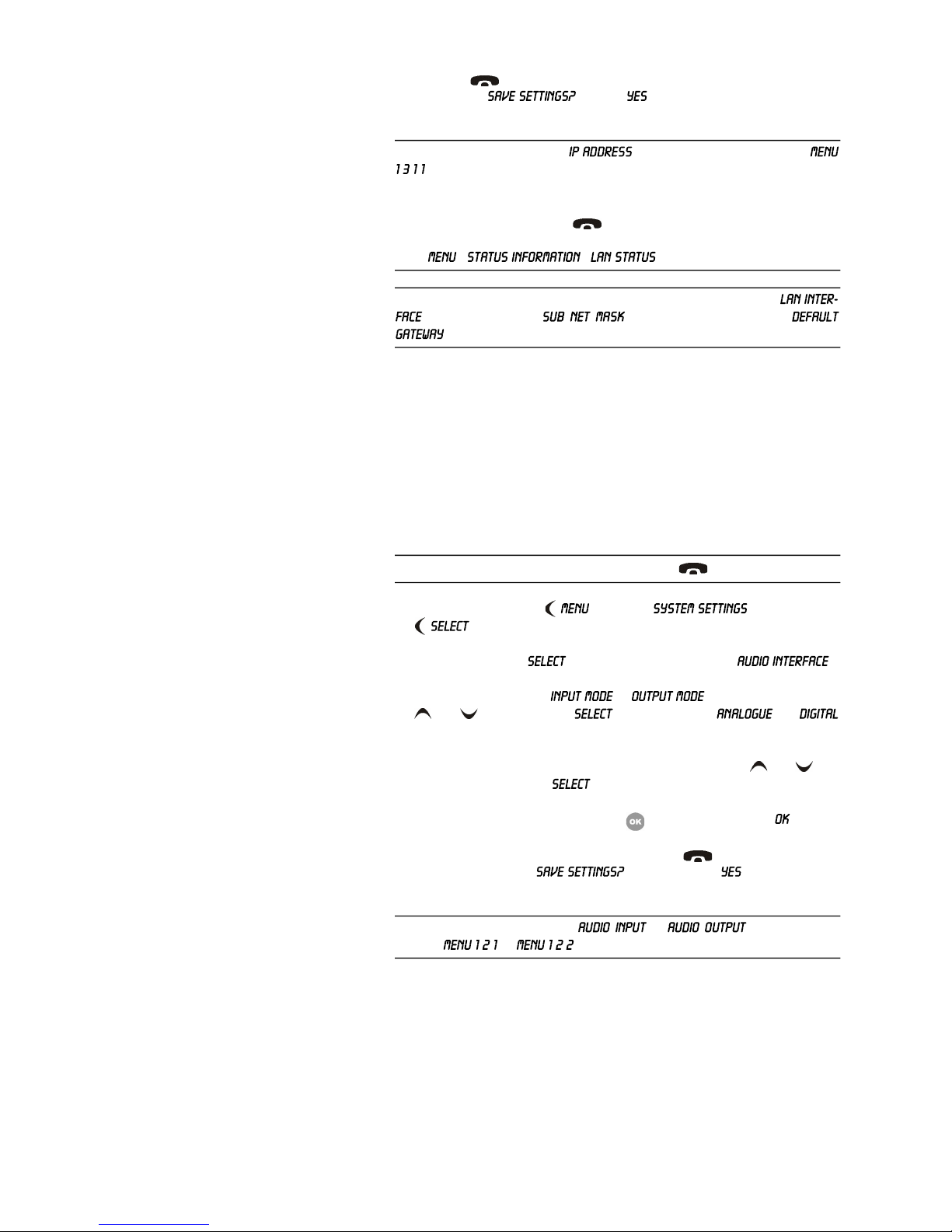
4.2.1 Selecting the menu language
In delivery status is selected as standard menu language. In order to
select as menu language, please follow the instructions below:
First press the softkey and select using the softkey
. Press the cursor key once until the option is displayed
in the menu. Via the softkey you directly reach the options for the
desired language. With the help of the cursor keys and please choose
the language and press again .
Please confirm your entry be pressing the button or the softkey.
To get back to the main menu, please press the key. Now you are asked
if you want to Via the softkey the settings are stored permanently in the system.
4.2.2 Configuration of the LAN Interface
To configure the LAN interface follow the instructions below:
– Press the softkey.
– Please mark the option via the cursor keys and
and press the softkey.
– Use the cursor keys and to get to the option and press
the softkey.
Select and to enter or change the IP Address of the system, mark the option and press the softkey.
– Now you can enter the correct IP Address via the numerical keypad.
NOTE
All menus can be reached directly via a QuickMenu key sequence. For this
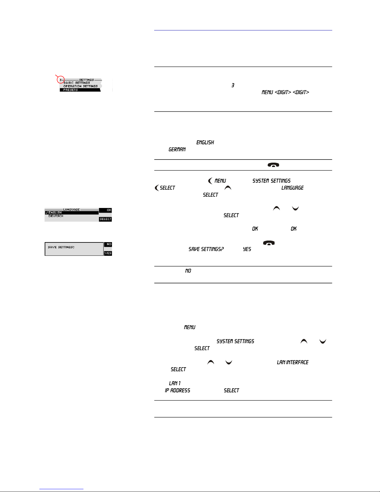
purpose each menu item is marked with a cypher in the upper left corner (in
the example on the left it is e. g. ). To reach a certain menu directly please
enter from the main menu the key sequence whereby
<digit> marks the respective menu reference number. Please notice that the
menu reference number can change depending on the configuration.
NOTE
If you are not in the main menu please press the key first.
NOTE
If you press , all settings that you have made are lost when the unit is
switched off.
NOTE
The default IP address is 192.168.96.102. For further information take a look
at Page 30.
Menu referen ce numbe r
Page 25
PAG E 2 5
O p e r a t i o n v i a D i s p l a y a n d K e y p a d
– Press the key to get back to the main menu. Now you are asked if
you want to . Via the softkey, the configuration is
stored in the system.
4.2.3 Setting the Audio interface: Analogue or digital
MAGIC AE1 DAB+ incorporates analogue as well as digital Audio interfaces
which you can adjust separately. The digital AES/EBU interfaces have integrated Sample Rate Converters to adjust the digital Audio source to the trans-
mission clock. Additionally, clock inputs/outputs are also available. To configure the Audio interface please follow the instructions below:
– First press the softkey and select via the softkey
.
– With the use of the softkey you reach the option .
– Please mark the option or using the cursor keys
and and press again . Now the options and
are displayed.
– Select the desired interface with the help of the cursor keys and and
by pressing the softkey .
– Confirm your entry by pressing the button or the softkey .
– To get back to the main menu please press the button. Now you are
asked if you want to . Via the softkey the setting is
stored permanently in the system.
TIP
You reach the settings for the directly via the key sequence:
.
The currently allocated IP address of the system can also be displayed by
pressing the telephone button on the front keypad of the system twice
if currently no Audio connection is established. During a connection you can
go to - - to check the IP address.
NOTE
Maybe further settings which can also be found under the option
are necessary (e.g. , standard: 255.255.0.0, and
). Please ask your network administrator for the correct settings.
NOTE
If you are not in the main menu please press the button first.
TIP
You reach the settings for the or via the key sequence: or
Page 26
PAG E 2 6
O p e r a t i o n v i a D i s p l a y a n d K e y p a d
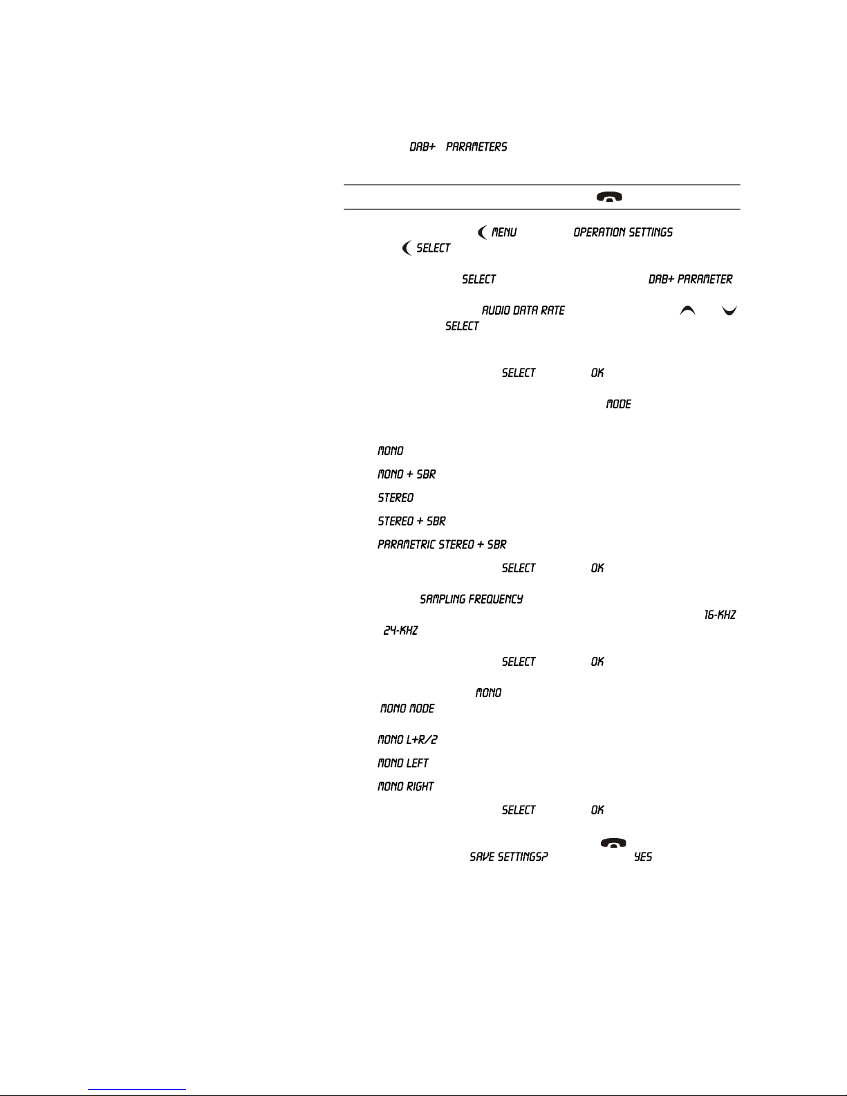
4.2.4 Configuring the DAB+ parameters
If the MAGIC AE1 DAB+ works together with a MAGIC DAB MUX Multiplexer, the Encoder parameters can be easily configured from the Multiplexer.
If required, the DAB+ parameters can be adjusted via the front panel under
the menu . For more information please refer to
CHAPTER 5.5.2.1.3, Page 44.
– First press the softkey and select via the
softkey .
– With the use of the softkey you reach the option .
– Please mark the option using the cursor keys and
and press again . Now the desired maximum Audio bit rate can be
set.
– Confirm the selection with and press .
– To configure the desired mode select the menu . Up to five possibili-
ties depending on the bitrate are available:
–
–
–
–
–
– Confirm the selection with and press .
– Select now to configure the Sampling Frequency. If
you have selected a SBR mode only the low sampling frequencies
and are possible
– Confirm the selection with and press .
– If you have selected a mode you have three further possibilities for
the :
– .
–
–
– Confirm the selection with and press .
– To get back to the main menu please press the button. Now you are
asked if you want to . Via the softkey the setting is
stored permanently in the system.
NOTE
If you are not in the main menu please press the button first.
Page 27

PAG E 2 7
O p e r a t i o n v i a D i s p l a y a n d K e y p a d
4.3 The Status Display - Operation during a connection
When the connection is established the level meter as well as the status for the
selected monitoring signal is displayed.
In the first row the program name, audio bitrate, coding mode (M=Mono,
S=Stereo, PS=Parametric Stereo), sampling frequency (16, 24, 32, 48) and PAD
bitrate (in kbit/s) is shown.
Softkey Monitor
During a connection you can switch via the softkey between original audio signal which is feed into the encoder and the decoded audio signal. Both
the audio output (XLR) and the head phone will be switched to the selected
audio signal. The display shows the monitoring status as follows:
– , if you monitor the original audio input signal
– , if you monitor the coded audio signal
Softkey Menu
Using the softkey you can change all parameters of the system at any
time.
Headphone Level
If a connection is established you can adjust the headphone level with the navigation buttons and . The current selected level will be shown in the
display.
Dropping a connection
The connection is dropped by pressing the telephone receiver button . If
no connection exists, the main menu is displayed after a few seconds. To
avoid errors you must confirm the drop request.
Establishing a connection
The connection is normally establishing automatically after power on. After
dropping a connection manually you can reconnect the line by pressing the
telephone receiver button .
TIP
The status window can always be reached by pressing the button.
Monito r Mode: Ori ginal or Coded
Page 28

PAG E 2 8
O p e r a t i o n v i a D i s p l a y a n d K e y p a d
4.4 Working with Presets
The MAGIC AE1 DAB+ differentiates between and
.
System Settings are settings that do not change during normal operation like
e.g. display contrast, date/time etc. These parameters cannot be saved as pre-
set since a configuration is usually only required when the system is put into
operation.
Operation Settings need to be reconfigured depending on the application. To
easily recall recurring configurations you can store up to 10 presets in the system.
You reach the menu for the Presets by pressing the softkey once, the cursor key twice and by pressing the softkey once as confirmation.
In the input field you can search for a certain Preset. As soon as you
enter a character, the corresponding entries of the Preset list are filtered out.
Alternatively, you can select a Preset from the list using the cursor keys
and .
If you now press the button, the selected Preset is loaded immediately.
By the softkey (Options) the following functions which you can select via
the softkey are realised:
– : The stored Preset is loaded.
– : With the help of this function you can create a new Preset. All current
Operation Settings are stored.
– : The currently selected Preset is overwritten with the current Opera-
tion Settings. For safety reasons a confirmation is required.
– : The currently selected Preset is deleted. For safety reasons
a confirmation is required.
– : All settings will reset to the factory settings. For
safety reasons a confirmation is required.
NOTE
If the configuration has changed, you are asked if you want to
when you leave the Preset menu. Via the softkey the configuration is
stored permanently in the system. This Preset is loaded automatically by the
system after the unit is connected to the power supply.
Page 29

PAG E 2 9
W i n d o w s P C S o f t w a r e
5 W I N D O W S P C S O F T W A R E
The configuration of the system is particularly comfortable via the Windows
PC Software included in delivery.
5.1 Hardware requirements
The PC must meet the following minimum requirements:
– IBM PC AT, IBM PS/2 or 100% compatible
– Pentium Prozessor (> 1 GHz) recommended
– Windows 7/8/10
– ca. 600 kByte available RAM
– 100 MB available hard disk space
– Screen resolution with 800 x 600 Pixels
– LAN interface or RS232 interface
– Microsoft, IBM PS/2 or 100% software compatible mouse
5.2 Installing the Windows PC Software
Please insert the CD included in delivery in your CD ROM drive. The software automatically starts your Internet browser. Possible safety warnings can
be ignored for the moment. Please press under Install Software the MAGIC
AE1 DAB+ button. Subsequently, the setup program is executed.
Alternatively, you can install the software directly from the CD. You will find
the installation file setup.exe in the folder Software\MAGIC AE1 DAB &
DAB+ on the CD.
Please note that this software can be used with MAGIC AE1 DAB as well as
MAGIC AE1 DAB+ systems.
Please follow the instructions of the installation routine.
After the installation the software can be started by clicking on the MAGIC
AE1 DAB+ icon.
Please connect your PC via a serial 1:1 cable (only Pin 2 and Pin 3 are used, Pin
5=ground) or preferably via LAN cable with the system.
The standard COM Port settings are: 38400 Baud
Page 30

PAG E 3 0
W i n d o w s P C S o f t w a r e
The default IP addresses and the default ports are:
IP address 1: 192.168.96.102
1
IP address 2: 192.168.96.103
(optional LAN2 interface)
Audio Port: 7000
Control Port 1: 10000
Control Port 2: 10001
Control Port 3: 10002
Control Port 4: 10003
Operation via Windows PC software
In the following chapters all functions of the PC software are described in detail.
1
The configured system IP address can be checked via the display (
).
Page 31
PAG E 3 1
W i n d o w s P C S o f t w a r e
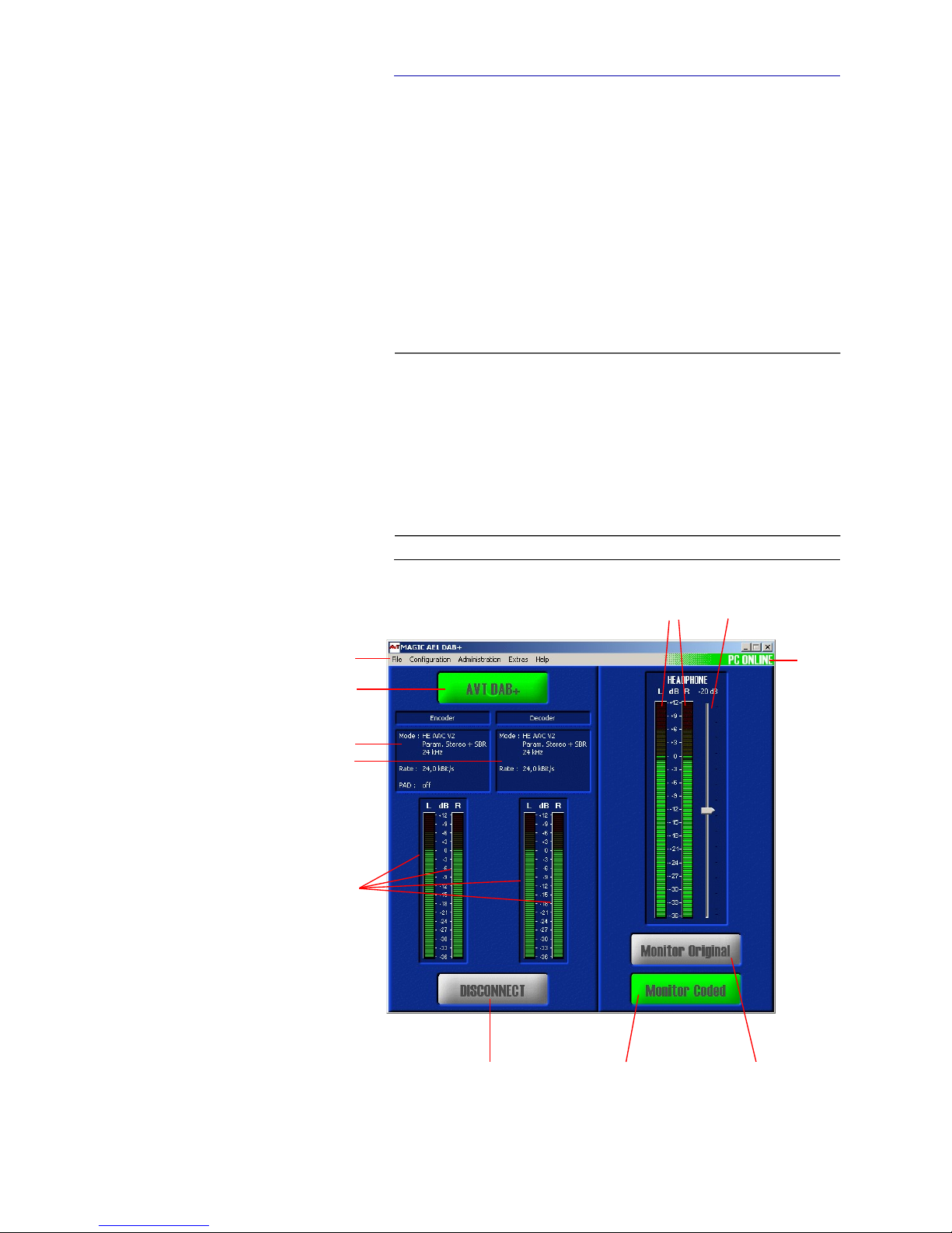
5.3 MAGIC AE1 DAB+ main window
After starting the MAGIC AE1 DAB+ application, the main window is displayed
automatically (see Fig. 7).
The connection status between PC and system is displayed in the top right
corner of the window:
PC ONLINE: Connection is okay.
NO CONNECTION: Connection with PC is faulty
Following further status messages are possible:
PC ONLINE ALARM: Upcoming alarm (see System Monitor, blinking)
FIG. 7 MAIN WINDOW OF THE PC SOFTWARE
NOTE
If the connection is faulty, please check the following points:
– Power supply cable of the system is plugged in and the system is switched
on (display available)
– Serial 1:1 cable or LAN is connected with PC and system
– Using RS232 interface: Correct COM port and same baud rate are selected
in the software as well as in the system (Configuration Control Inter-
face, see Page 34)
– Using LAN interface: Correct IP address and port is selected in the soft-
ware as well as in the system (Configuration Control Interface, see
Page 34)
Menu bar
Programme name
Encoder status
Monitoring Decoder
status
Switching between coded and original Audio signal
Level meter
Headphone
Headphone
volume control
PC
status
(double-
click
to open
System
Monitor)
Level meter
Encoder/
Decoder
Connect/Disconnect
Line Connection
Page 32
PAG E 3 2
W i n d o w s P C S o f t w a r e
5.3.1 Operating elements
Info button
On the Info button the programme name is shown. The programme name can
be configured via Configuration MAGIC AE1 DAB+ Operation Set-
tings Encoder Parameters Programme Name.
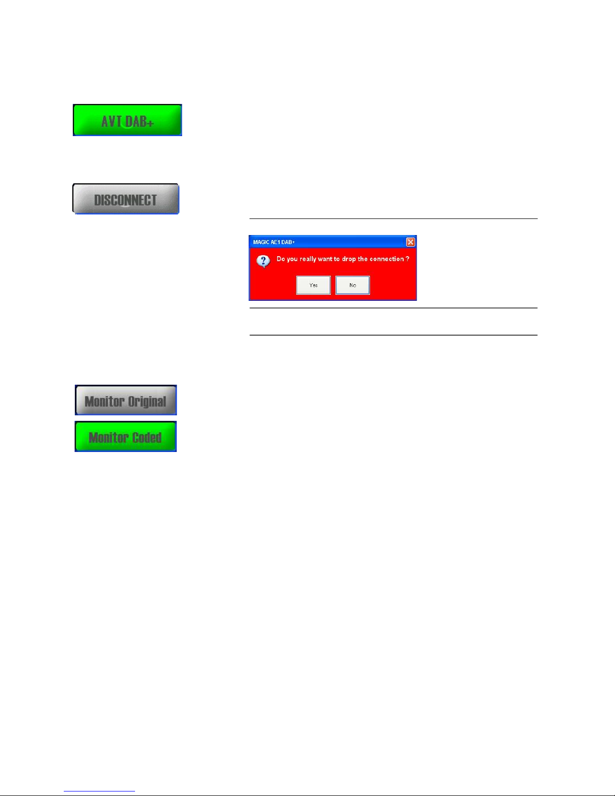
Connect/Disconnect button
To stop the transmission you can press the Disconnect button. For security
reasons you must confirm this action.
FIG. 8 CONFIRMATION OF DROPPING A CONNECTION
Monitoring Coded/Original
Via the Monitor Coded and Monitor Original buttons you can select the output of the monitoring decoder. The currently selected source is highlighted in
green.
To adjust the headphone level use the Headphone Volume Control, which
allows an adjustment in a of range of -40 ... 0 dB.
NOTE
If the connection is dropped, the level meter for the encoder as well as the Info
button will be displayed grey coloured.
Page 33

PAG E 3 3
W i n d o w s P C S o f t w a r e
5.4 Menu file
FIG. 9 MENU FILE
5.4.1 Operation Settings Presets
To Import/Export All the different presets please use the submenu Operation Settings Presets. The file format (.pst) is binary and cannot be edited.
5.4.2 System Settings
To Import/Export the system configuration please use the submenu System
Settings. The file format (.tcg) is binary and cannot be edited.
5.4.3 Submenu Exit
Via the submenu Exit you close the MAGIC AE1 DAB+ software.
Page 34
PAG E 3 4
W i n d o w s P C S o f t w a r e
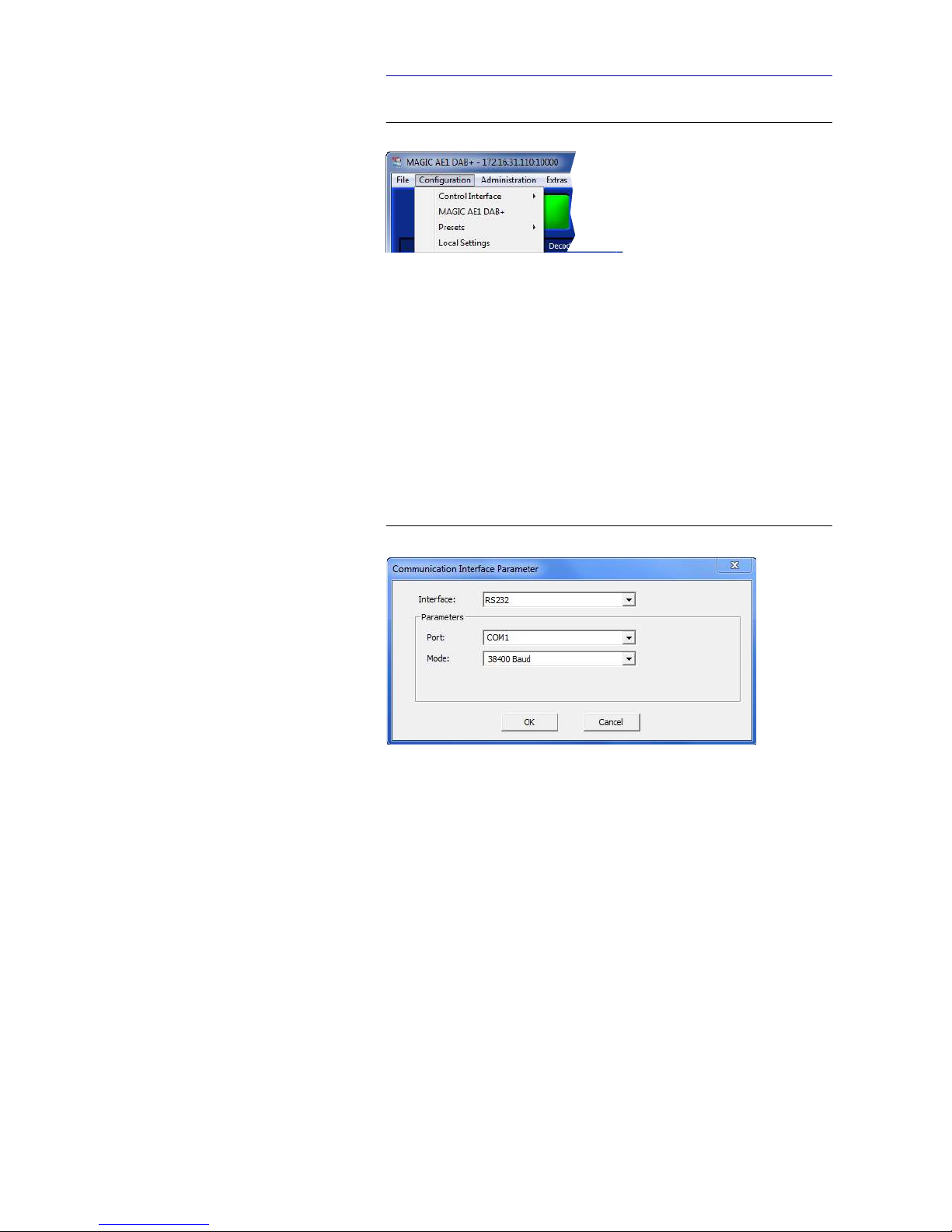
5.5 Menu Configuration
FIG. 10 MENU CONFIGURATION
5.5.1 Submenu Control Interface
The system can be connected via the serial RS232 interface with a 1:1 connect-
ing cable or via the LAN interface to a PC. The configuration of the Control In-
terface of the PC can be carried out under Configuration Control Interface Configuration.
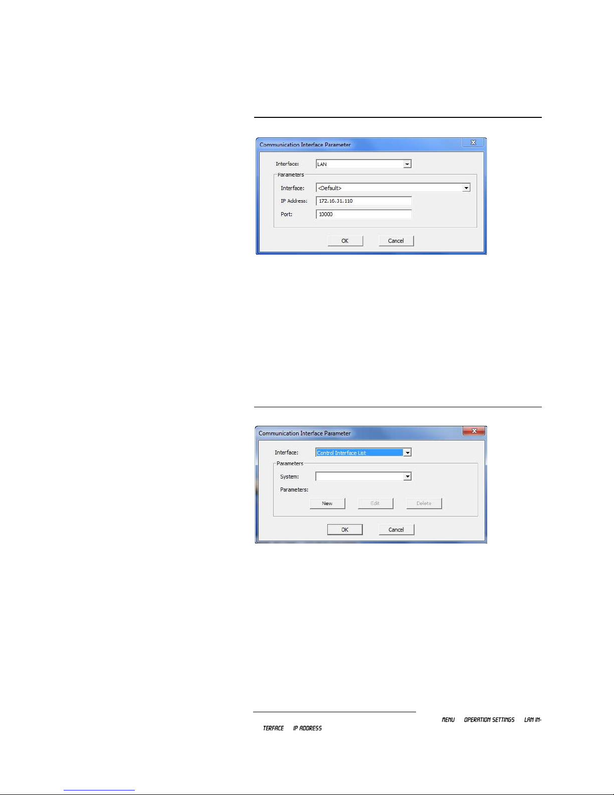
Using the RS232 interface
If you want to use the RS232 interface select via the drop-down list Interface
RS232.
FIG. 11 CONFIGURATION OF THE COM PORT
As Port you select the interface of your PC which is connected to the MAGIC
AE1 DAB+.
Under Mode you can set the desired operating mode:
– 9600 Baud
– 19200 Baud
– 38400 Baud
– 57600 Baud
– 115200 Baud
All further parameters like Data Bits, Parity and Stop Bits cannot be config-
ured.
Page 35
PAG E 3 5
W i n d o w s P C S o f t w a r e
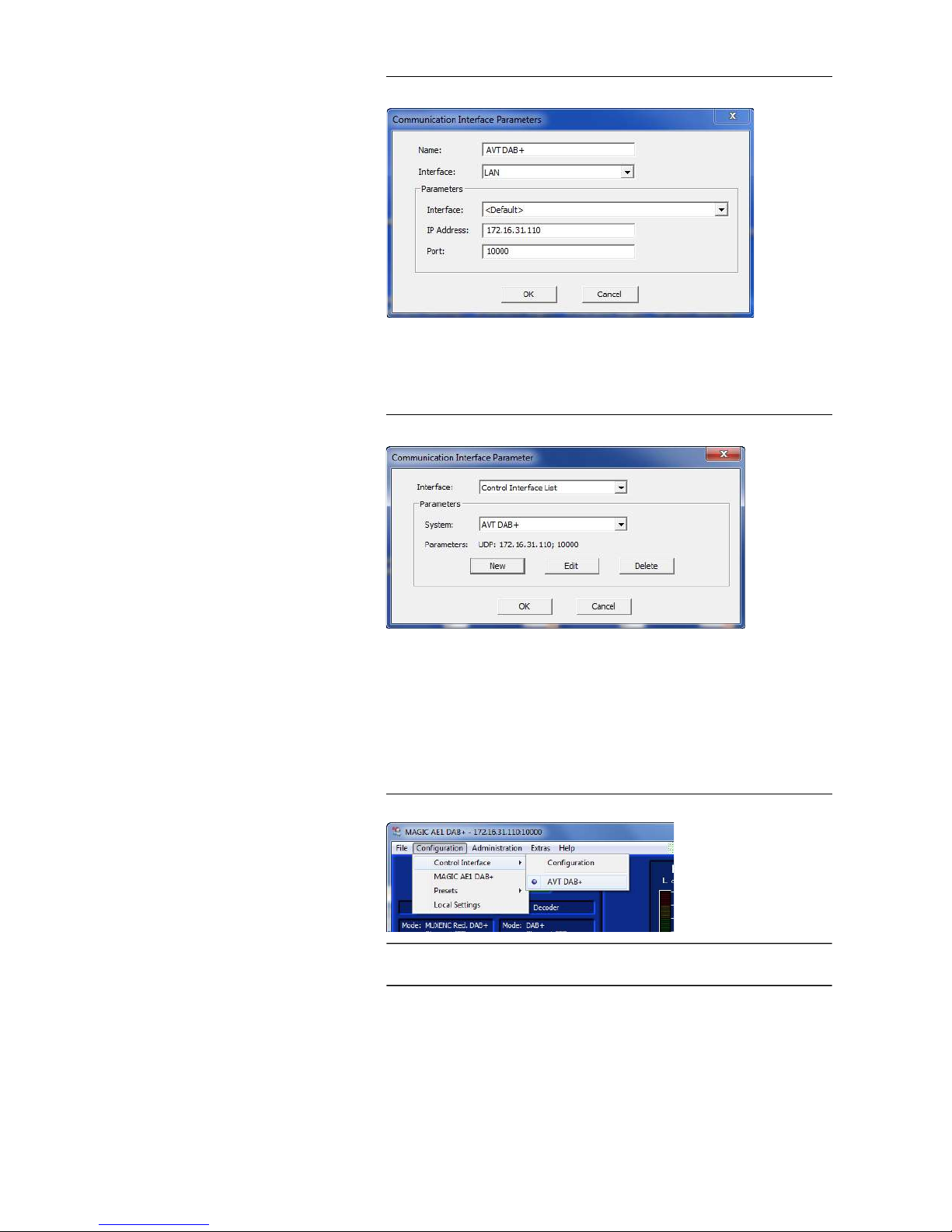
Using the LAN interface
To control the system via your local network you can connect the LAN interface of the system to your IP network. Select via the drop-down list Interface
LAN.
FIG. 12 CONFIGURATION OF THE LAN INTERFACE
Under Parameter you have to select the used LAN interface of your PC. If
only one Network Card is installed you shall use the setting <Default>.
Enter the right IP Address and Port of the desired system1.
Control of multiple systems via the Control Interface List
If you have more than one system connected via the LAN or RS232 interface
you can manage all connection parameters via the Control Interface List.
FIG. 13 USING THE CONTROL INTERFACE LIST
Press New to add a new system.
1
The configured LAN settings can be checked via the display (
).
Page 36
PAG E 3 6
W i n d o w s P C S o f t w a r e
FIG. 14 ADDING A NEW SYSTEM
Enter a Name, the used interface LAN or RS232 for the desired system and
the correct communication parameters.
FIG. 15 EDITING OR DELETING A SYSTEM
With the Edit button you can change the parameters of the selected system.
With Delete you can remove the system from the Control Interface List.
If you have added all systems to your list you can simply select via Configu-
ration Control Interface the desired system.
FIG. 16 SELECTION OF A SYSTEM VIA LIST
NOTE
With the MAGIC AE1 DAB LAN software which is also included in the delivery
up to 60 systems (tree display) can be monitored and controlled.
Page 37
PAG E 3 7
W i n d o w s P C S o f t w a r e
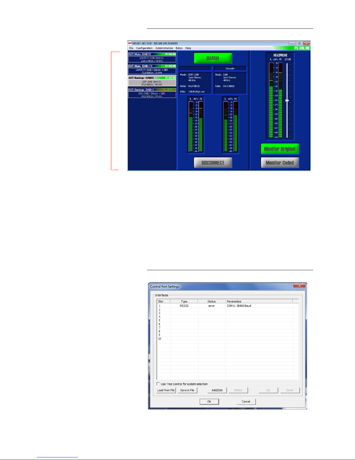
FIG. 17 MAGIC AE1 DAB LAN - MULTI CONTROL (LIST VIEW)
When the PC Software is executed, the MAGIC AE1 DAB LAN Software is automatically installed together with the MAGIC AE1 DAB Software. To start the
MAGIC AE1 DAB LAN Software, simply click on the corresponding desktop
icon.
The Encoders in the connection list are displayed with their status PC Online,
PC Offline or PC Online Alarm (see Page 31). You can also see the Pro-
gramme’s name and the connection details.
The configuration of the systems which are to be connected to the multi control software can be carried out under Configuration Control Interface.
FIG. 18 CONTROL PORT SETTINGS
LIST OF
ALL CONNECTED
DAB/DAB+ ENCODER
Page 38
PAG E 3 8
W i n d o w s P C S o f t w a r e
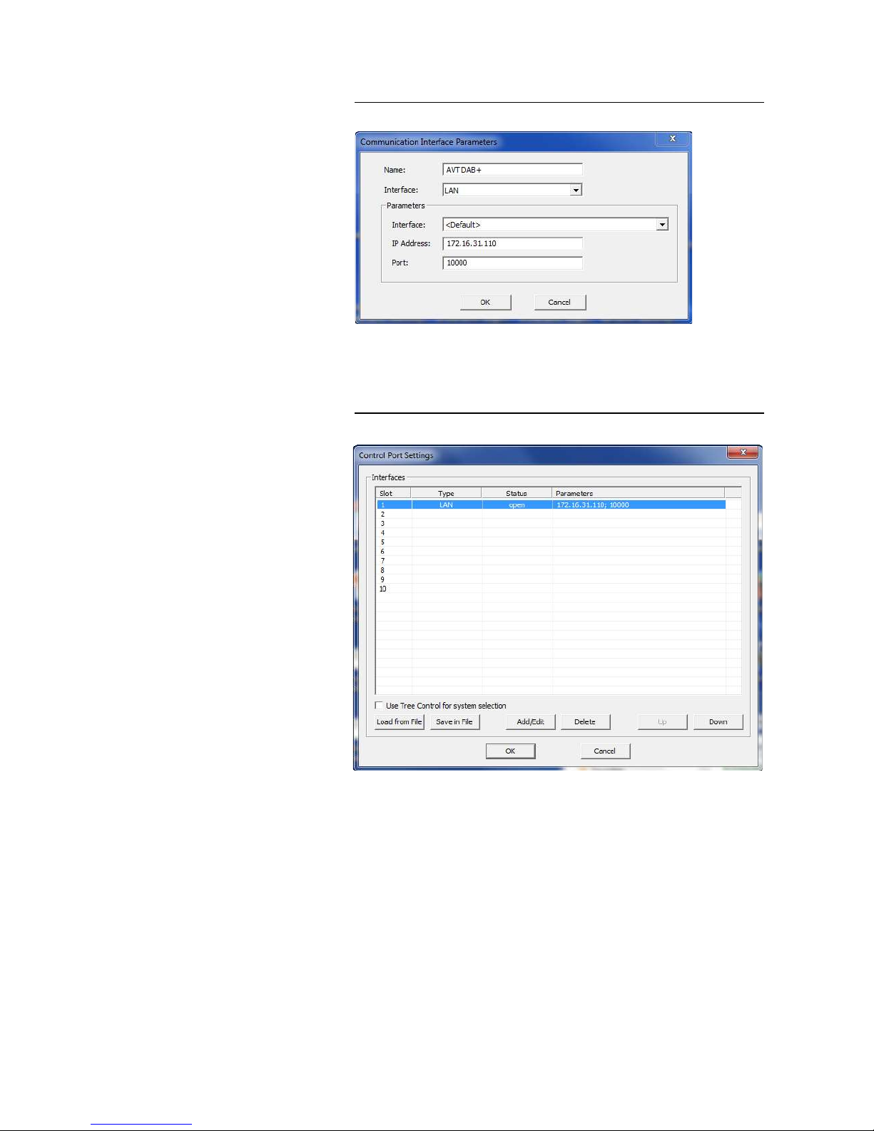
Press Add/Edit to add a new system or double-click on a free line.
FIG. 19 ADDING A NEW SYSTEM
Enter a Name, the used interface LAN or RS232 for the desired system and
the correct communication parameters.
FIG. 20 CONTROL PORT SETTINGS 2
With the Add/Edit button you can change the parameters of the selected system.
With Delete you can remove the system from the connection list.
It is also possible to save the connection list in a file (Save in File) e.g. as
backup or for importing it at another workplace. The file has the extension .ifl.
With Load from File you can import an existing .ifl file.
The buttons Up and Down can be used to change the order of the entries.
In the standard list, maximum 10 systems can be displayed. By using the tree
display you can enter up to 60 systems. For this, please activate the function
Use Tree Control for system selection.
Page 39
PAG E 3 9
W i n d o w s P C S o f t w a r e
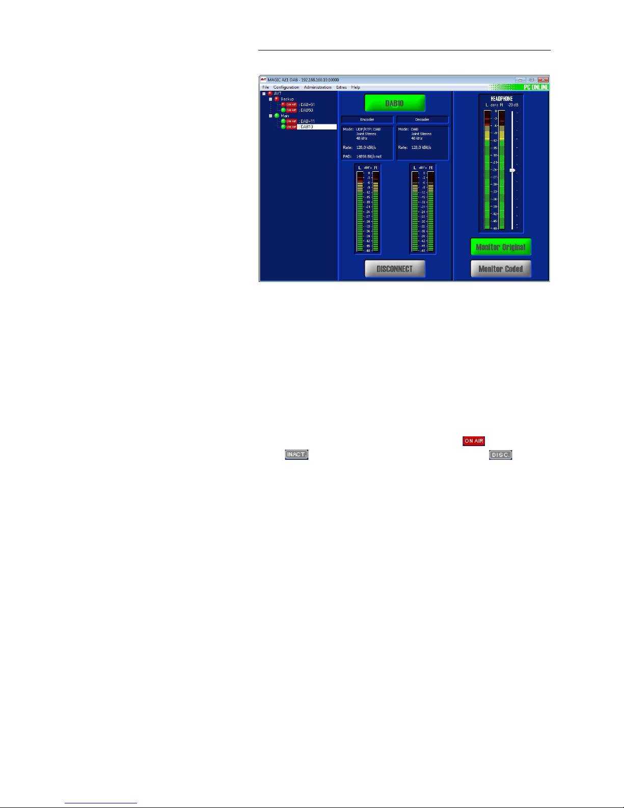
FIG. 21 MAGIC AE1 DAB LAN - MULTI CONTROL (TREE VIEW)
With entering a group name under System Settings General System
Name several Encoders can be summarized in groups (e.g. MAIN &
BACKUP) for the tree view. As a separator the “-“ character is used:
Syntax: <Group>-<System>
The System Name consists of maximal 15 characters (A-Z, a –z and 0-9 plus
the ’-’).
If configured in the settings of the MAGIC DAB MUX Multiplexer, the Encoders
in the connection list are marked with the symbols (Encoder is ON
AIR), (Encoder is inactive, e.g. Backup Encoder) or (Encoder
is deactivated).
The LEDs can be displayed in three different colours:
– green: no alarm
– red: active alarm
– blue: alarm has occurred but is no longer active
Page 40
PAG E 4 0
W i n d o w s P C S o f t w a r e
5.5.2 Submenu MAGIC AE1 DAB+
Via the submenu MAGIC AE1 DAB+ the system can be configured comforta-
bly. It is distinguished between System Settings, which do not have to be
changed during the operation and Operation Settings for the current application. In contrast to a operation setting, the system settings cannot be saved
as Preset (see CHAPTER 5.5.3).
5.5.2.1 Operation Settings
5.5.2.1.1 Line interface
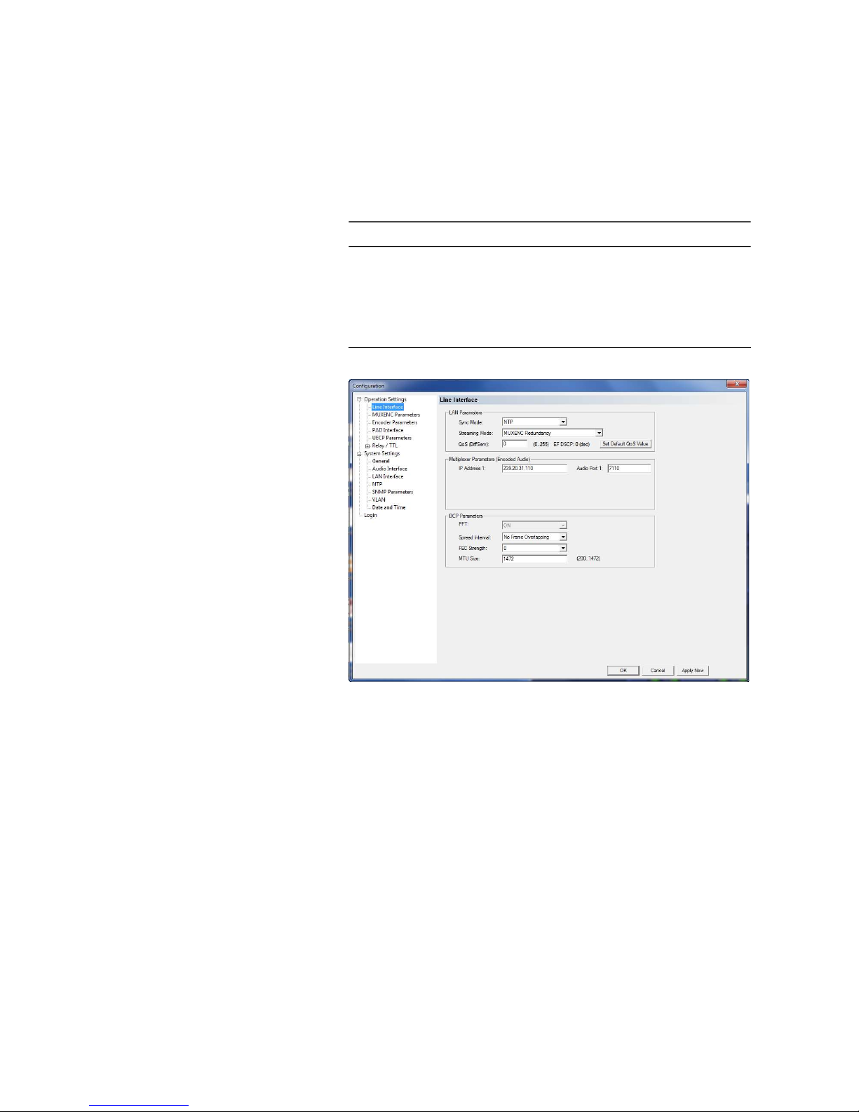
Under Line Interface you can configure the settings which are necessary for
the connection between Audio Encoder and Ensemble Multiplexer.
FIG. 22 LINE INTERFACE
LAN Parameters
• First, you need to select which Sync Mode you want to use to synchronise
the Audio Encoder and the Ensemble Multiplexer. The following modes
can be configured:
– AES/EBU: If you want to use the digital AES/EBU clock to synchronise
the systems, please select this setting. Please note that a GPS clock is
necessary in this case.
– NTP: If your MAGIC AE1 DAB+ Encoders are connected to the AVT MAGIC
DAB MUX Multiplexer, please select NTP as Sync Mode. The NTP Server
which is providing the clock has to be configured under System Set-
tings NTP.
– Internal: This setting should only be selected if no other clock is avail-
able. In this case, it is very likely that dropouts will occur.
NOTE
All listed settings made under Operation Settings can be saved as Preset.
Page 41

PAG E 4 1
W i n d o w s P C S o f t w a r e
– Auto: In this mode, the Encoder detects automatically which mode to
use. First choice is NTP. If NTP is not configured or if the NTP Server is
not available, the system switches to AES/EBU. If also the AES/EBU
clock is not available, it switches to Internal.
• Under Streaming Mode you have to configure which protocol is used for
the communication between Audio Encoder and Ensemble Multiplexer.
The options are:
– UDP stream using RTP: Set this option if you want to use UDP with
RTP. You must set the RTP option on both sides (Encoder and Multiplexer). Please select this protocol if the Encoder is connected to a VDL
D-Vaudax Multiplexer.
The RTP1 protocol describes the transmission of multimedia content
(e.g. audio or video) via IP networks. The sequence numbers included
in RTP allow the receiver to reconstruct the sender's packet sequence,
but sequence numbers might also be used to determine the proper location of a packet.
Note that RTP itself does not provide any mechanism to ensure timely
delivery or provide other quality-of-service guarantees, but relies on
lower-layer services to do so. It does not guarantee delivery or prevent
out-of-order delivery, nor does it assume that the underlying network
is reliable and delivers packets in sequence.
– EDI (optional): Select this option if you want to use the EDI protocol
for the communication between Audio Encoder and Ensemble Multiplexer. The EDI protocol is a fee-based software option (product ID
800989).
– MUXENC (optional): If your MAGIC AE1 DAB+ Encoders are connected
to the AVT MAGIC DAB MUX Muliplexer and you do not have a redundant
setup, please select MUXENC as Streaming Mode. This allows also a
configuration of the Encoders as well as PAD insertion via the Multiplexer. The MUXENC protocol is a fee-based software option (product
ID 800999).
– MUXENC Redundancy (optional): If your MAGIC AE1 DAB+ Encoders
are connected to the AVT MAGIC DAB MUX Muliplexer and you have a re-
dundant setup, please select MUXENC Redundancy as Streaming
Mode. This allows a configuration of the Encoders as well as PAD in-
sertion via the Multiplexer. The MUXENC protocol is a fee-based software option (product ID 800999).
• If your network supports Quality of Service (Differentiated Services) you
can enter the desired value between 0...255 under QoS (DiffServ). Or you
can also use the Set Default QoS Value button. This button sets the value
to 184.
1
RTP = Real Time Transport Protocol (RFC 3550)
NOTE
If you have purchased a complete headend from AVT with the MAGIC DAB
MUX Basic or Professional Multiplexer, the EDI Upgrade and the FhG MUXENC
Upgrade (for MUXENC and MUXENC Redundancy) are activated free of
charge in your Audio Encoders.
Page 42

PAG E 4 2
W i n d o w s P C S o f t w a r e
Multiplexer Parameters (Encoded Audio)
• IP Address 1: Here you have to enter the IP address of your Ensemble
Multiplexer.
• Audio Port 1: Here you have to enter the Audio Port which is used for the
transmission between the Audio Encoders and the Multiplexer.
DCP Parameters
• The PFT (Protection, Fragmentation & Transport Layer) is always set on
and cannot be switched off.
• Under Spread Interval you can select how many frames are overlapping
during the transmission. The higher the spread interval (more frames
overlapping), the better the protection when a burst error occurs. However, a higher spread interval also increases the delay because a higher
buffer is required.
• Under FEC Strength you can select which protection level you would like
to use (0...3). The higher the protection level, the higher the required transmission bit rate. The FEC strength defines the number of packets that can
be recovered via FEC. However, please note that the higher the FEC
strength, the higher is also the number of packets transmitted.
• Under MTU Size (maximum transmission unit) the maximum packet size
can be defined.
5.5.2.1.2 MUXENC Parameters
If you have selected a Streaming Mode which uses the MUXENC protocol under the Line Interface menu, the MUXENC Parameters menu will be displayed.
NOTE
If you want to use a redundant multiplexer with the same Audio Encoder the
IP multicasta function can be used. In this case you have to use a multicast IP
address (range: 224.0.0.0 to 239.255.255.255).
a Otherwise the IP packets are transmitted in unicast mode.
NOTE
If your MAGIC AE1 DAB+ Audio Encoder is connected to the MAGIC DAB MUX
Multiplexer and the MUXENC protocol is used, the DCP Parameters can be se-
lected in the Multiplexer configuration and are transmitted automatically to
the Audio Encoder.
Page 43

PAG E 4 3
W i n d o w s P C S o f t w a r e
FIG. 23 MUXENC PARAMETERS
Content Provider
Under Login you have to enter the name which you have defined in the
MAGIC DAB MUX Multiplexer configuration under Content Provider Login
when setting up the MAGIC AE1 DAB+ Audio Encoder as Service Component.
Network Delay
• Please enter your expected network delay in msec under Expected Delay.
Values from 0 to 1000 msec are allowed.
Multiplexer Multicast Reception Parameters (Control, PAD)
Here you have to define the backchannel from the Multiplexer to the Audio
Encoder so that they can be controlled via the Multiplexer and PAD can be
transmitted from the Multiplexer to the Audio Encoder.
• Please enter under Group Address 1 the IP Address of your MAGIC DAB
MUX Multiplexer as well as the respective Port 1. If you have a redundant
setup, you have to enter the IP address of the backup Multiplexer under
Group Address 2 and enter Port 2.
Page 44
PAG E 4 4
W i n d o w s P C S o f t w a r e
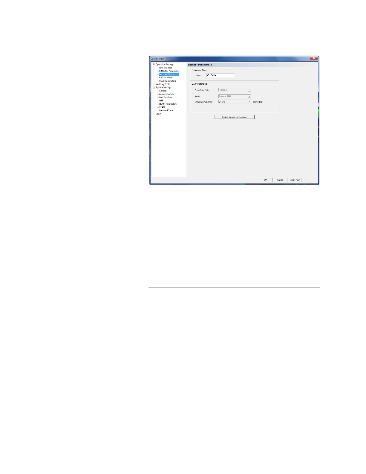
5.5.2.1.3 Encoder Parameters
FIG. 24 ENCODER PARAMETERS
Programme Name
• Here you can enter the Name of the programme. It will be displayed on
the Info button in the main user interface of the PC Software as well as in
the connection list if you are using the multi control MAGIC AE1 DAB+ LAN
Software.
DAB+ Parameter
All possible data rates, modes and sampling frequencies you can see in
TAB. 1, Page 45.
• Audio Data Rate: With this setting you can define the data rate of the
coded Audio signal.
• Mode: This option allows to configure the coding mode. Five options depending on the selected bitrate are available:
– Mono
– Mono + SBR
– Stereo
– Stereo + SBR
– Parametric Stereo + SBR
• Sampling Frequency: Depending on the selected bitrate you can define
here the desired sampling frequency. The following sampling frequencies
are possible:
NOTE
If your MAGIC AE1 DAB+ Audio Encoder is connected to the MAGIC DAB MUX
Multiplexer and the MUXENC protocol is used, the DAB+ Parameters can be
selected in the Multiplexer configuration and are transmitted automatically
to the Audio Encoder.
Page 45

PAG E 4 5
W i n d o w s P C S o f t w a r e
– 16 kHz (only in SBR mode)
– 24 kHz (only in SBR mode)
– 32 kHz
– 48 kHz
• Mono Mode: If you have selected a Mono mode you have the following
Mono options:
– Mono L: Only the left channel of the audio input will be encoded
– Mono R: Only the right channel of the audio input will be encoded
– Mono (L+R)/2: If you have connected a Stereo signal this setting al-
lows the generation of a Mono signal.
TAB. 1 POSSIBLE DATA RATES AND MODES
Bitrate
kbit/s
Possible
Coding
Modes
SBR
a
a SBR = Spectral Band Replication
PS
b
b PS = Parametric Stereo
Possible
Sampling
Frequencies
kHz
8 Mono - - 32, 48
16 Mono, Stereo
¸ ¸
32, 48 (16, 24)
c
c In brackets = Sampling frequencies, if SBR is activated
24 Mono, Stereo
¸ ¸
32, 48 (16, 24)
32 Mono, Stereo
¸ ¸
32, 48 (16, 24)
40 Mono, Stereo
¸ ¸
32, 48 (16, 24)
48 Mono, Stereo
¸ ¸
32, 48 (16, 24)
56 Mono, Stereo
¸ ¸
32, 48 (16, 24)
64 Mono, Stereo
¸ ¸
32, 48 (16, 24)
72 Mono, Stereo
¸
- 32, 48 (16, 24)
80 Mono, Stereo
¸
- 32, 48 (16, 24)
88 Mono, Stereo
¸
- 32, 48 (16, 24)
96 Mono, Stereo
¸
- 32, 48 (16, 24)
104 Mono, Stereo
¸
- 32, 48 (16, 24)
112 Mono, Stereo
¸
- 32, 48 (16, 24)
120 Mono, Stereo
¸
- 32, 48 (16, 24)
128 Mono, Stereo
¸
- 32, 48 (16, 24)
136 Mono, Stereo
¸
- 32, 48 (16, 24)
144 Mono, Stereo - - 32, 48
152 Mono, Stereo - - 32, 48
160 Mono, Stereo - - 32, 48
168 Mono, Stereo - - 32, 48
176 Mono, Stereo - - 32, 48
184 Mono, Stereo - - 32, 48
192 Mono, Stereo - - 32, 48
Page 46
PAG E 4 6
W i n d o w s P C S o f t w a r e
5.5.2.1.4 PAD Interface
If the MAGIC AE1 DAB+ Audio Encoder is connected to the MAGIC DAB MUX Mul-
tiplexer, PAD1 can be configured and inserted via the Multiplexer.
The data insertion works dynamically: If data is available the audio bit rate
will be reduced automatically according to the PAD bit rate. Otherwise the
full frame is used for audio.
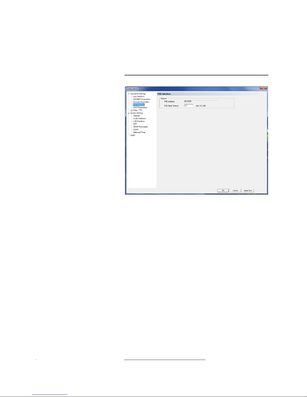
FIG. 25 PAD INTERFACE - MUXENC
General
• Under PAD Interface you will see that MUXENC is displayed when the
Encoder is connected to the MAGIC DAB MUX Multiplexer. PAD can be trans-
mitted using the MUXENC protocol from the Multiplexer to the Audio Encoder.
• Under PAD Alarm Timeout a threshold value can be defined. If no PAD is
received or inserted during the defined time frame, PAD alarms will be set
(see Page 80).
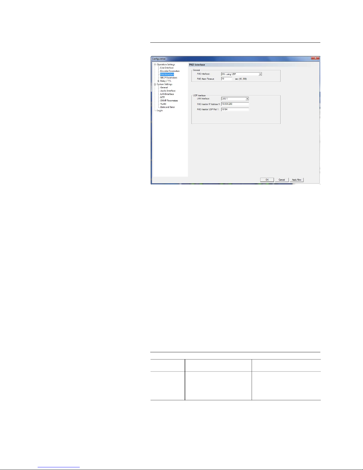
Alternatively, you can enable the PAD Insertion from an external PAD inserter. The standard settings are compliant to the synchronous frame mode of
the IRT Recommendation.
To enable the PAD transmission you must select your PAD Interface. The
available options are:
– OFF
– ON - using RS232
– ON - using UDP
– ON - using UDP (with redundancy)
1
PAD = Program Associated Data
Page 47
PAG E 4 7
W i n d o w s P C S o f t w a r e
FIG. 26 PAD INTERFACE - EXTERNAL PAD INSERTER
If you select UDP as your PAD Interface, the following parameters must be
configured under UDP Interface.
• LAN Interface: Please select via which LAN interface (LAN 1 or optionally
LAN 2) the Encoder receives PAD.
• PAD Inserter IP Address 1: Here you must enter the IP address of your
PAD inserter.
• PAD Inserter UDP Port 1: Here you must enter the UDP Port that is used.
• If you have a redundant PAD Inserter, the entry fields PAD Inserter IP Ad-
dress 2 and PAD Inserter UDP Port 2 are also available and must be filled
in.
If you select RS232 as your PAD Interface, the selected Baudrate must be
conform to the connected PAD inserter. Available baudrates are 38400,
57600, and 115200 Baud. The Parity and Stop Bits cannot be changed. The
standard settings are: 38400 Baud, Parity None and 1 Stop Bit.
The maximum bitrate for PAD insertion is defined in the ETSI TS 102 563
standard.
TAB. 2 MAXIMUM BITRATE OF F-PAD AND X-PAD DATA
Sampling Rate
F-PAD
2 byte
X-PAD
max. 196 bytes
16-kHz 267 bps 26133 bps
24-kHz 400 bps 39200 bps
32-kHz 533 bps 52267 bps
48-kHz 800 bps 78400 bps
Page 48
PAG E 4 8
W i n d o w s P C S o f t w a r e
5.5.2.1.5 UECP Parameters
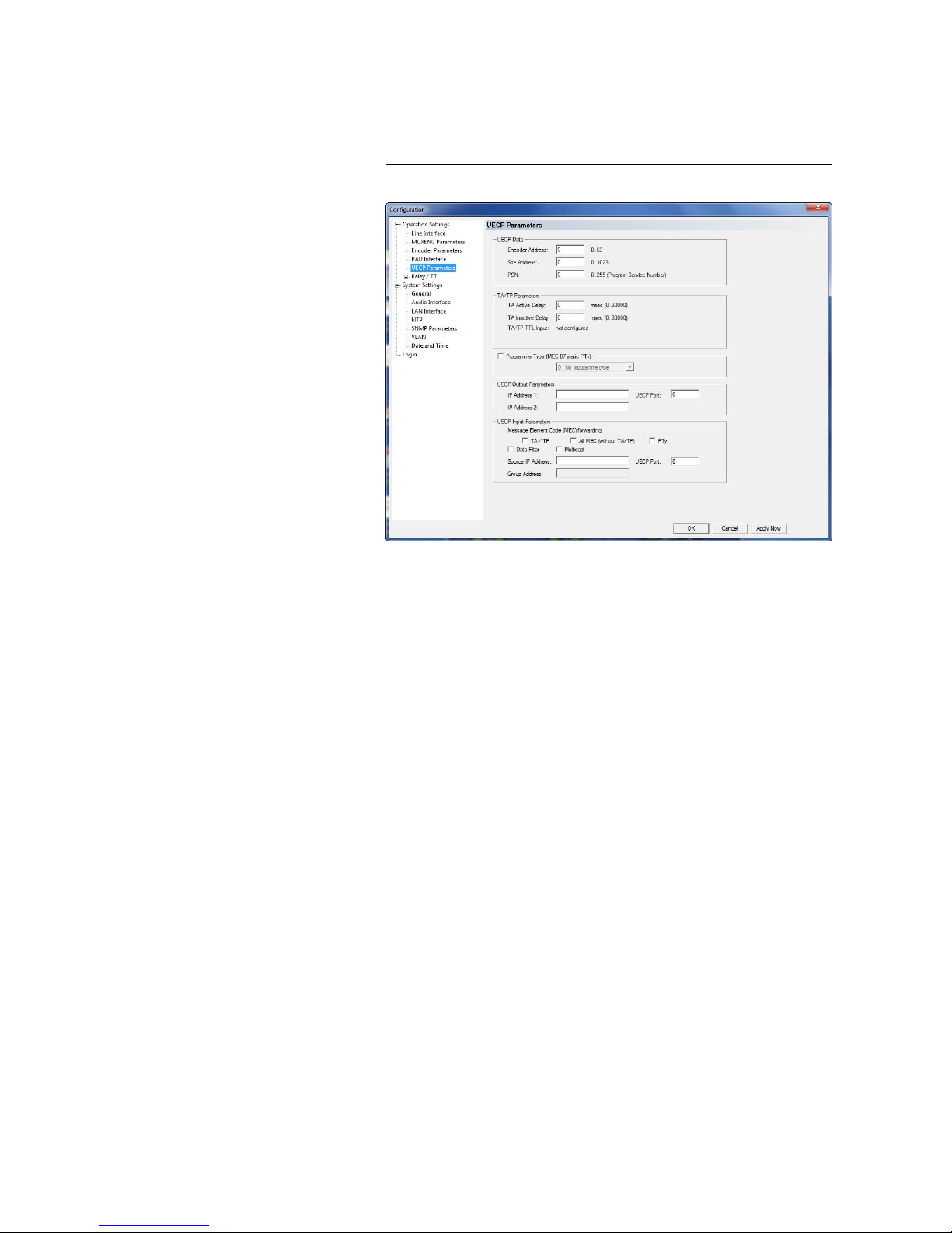
If UECP messages are to be inserted via the LAN interface, the parameters can
be defined in this menu.
FIG. 27 UCEP PARAMETERS
UECP Data
Under UECP Data you can enter the header data of the UECP Encoder if necessary. You can enter
– Encoder Address
– Site Address
– PSN (Program Service Number)
TA/TP Parameters
The transmission of the TA UECP messages can be delayed if required. This
can be e.g. useful if UECP messages from an FM programme are used since
the DAB+ signal will be transmitted with a delay (due to buffer, FEC etc.).
• Under TA Active Delay the transmission delay of the TA Active UECP
message can be entered in msec. The maximum delay is 300 000 msec.
• Under TA Inactive Delay the transmission delay of the TA Inactive UECP
message can be entered in msec. The maximum delay is 300 000 msec.
• Under TA/TP TTL Input it is displayed if a TTL Input is configured for
sending TA UECP messages.
Page 49

PAG E 4 9
W i n d o w s P C S o f t w a r e
Programme Type (MEC 07 static PTy)
• If you want to configure and transmit a static Programme Type, please ac-
tivate the checkbox and select your Programme Type from the dropdown
list.
UECP Output Parameters
• Please enter under IP Address 1 the IP address of your Multiplexer and
under UECP Port the Port which is used.
• If you have a redundant setup, please enter the IP address of your backup
Multiplexer under IP Address 2.
UECP Input Parameters
• Under Message Element Code (MEC) forwarding you can select which
parameters of the UECP message are analysed and forwarded.
– TA/TP: Traffic Announcement/Traffic Programme
– All MEC (without TA/TP): e.g. Dynamic Label
– PTy: Programme Type
• If the checkbox Data Filter is enabled, only UECP messages that have the
data header with the values entered under UECP data are forwarded.
• Under Source IP Address please enter the IP Address from which the
UECP messages are received as well as the UECP Port.
• If the UECP messages are received from a multicast address, you have to
activate the Multicast checkbox and enter the multicast address under
Group Address.
Page 50
PAG E 5 0
W i n d o w s P C S o f t w a r e
5.5.2.1.6 Relay/TTL
The MAGIC AE1 DAB+ system incorporates six GPIO Pins (TTL) which can be
programmed separately as input or output. Additionally, two Relays are
available.
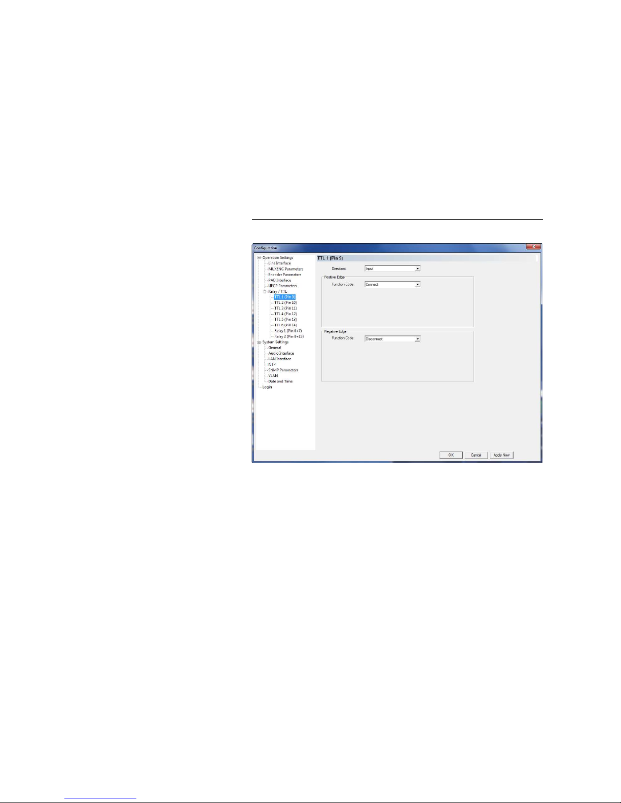
The operating mode of a TTL Pin - Input or Output is selected via the option
Direction.
The following specification accounts for all three configuration windows
TTL1 ... TTL6.
TTL Pin as input
FIG. 28 TTL PIN AS INPUT
If you use a TTL Pin as Input, you can program two different functions separately when edges change:
• Positive edge: The event is activated when the voltage on the TTL Pin
changes from 0V to +3,3V.
• Negative edge: The event is activated when the voltage on the TTL Pin
changes from +3,3V to 0V.
The following functions can be configured (Function Code):
– -: No function, the negative edge is not used.
– Connect:
Via this function you can establish a connection.
– Connect (level triggered):
Same function as Connect, but the event is activated level triggered
and not edge triggered.
– Disconnect: If you activate this function, a connection can be discon-
nected.
Page 51

PAG E 5 1
W i n d o w s P C S o f t w a r e
– Load Preset: Via this function it is possible to load a preset which you
have to select under Preset.
– Send UECP TA active: With this function, you can send the UECP TA
active message.
– Send UECP TA inactive: With this function, you can send the UECP
TA inactive message.
Example:
You want to connect the LAN line with TTL 1. After the transmission
has been finished the connection is to be cleared with TTL 1.
Programming:
Positive edge:
Function Code: Disconnect
Negative edge:
Function Code: Connect
FIG. 29 SEQUENCE OF EVENTS FOR THE EXAMPLE
15-pol. SUB-D connector
to MAGIC AE1 DAB+
(TTL/RELAY)
Switch is opened:
Pin 9 = TTL 1 is on +3,3 V (via internal 10 KOhm series resistance)
Switch is closed:
Pin 9 =TTL 1 is set to 0V (Pin 5):
Connection is established
Switch is opened:
Pin 9 =TTL 1 is set to +3,3V:
Line is disconnected
Switch
18
915
Page 52
PAG E 5 2
W i n d o w s P C S o f t w a r e
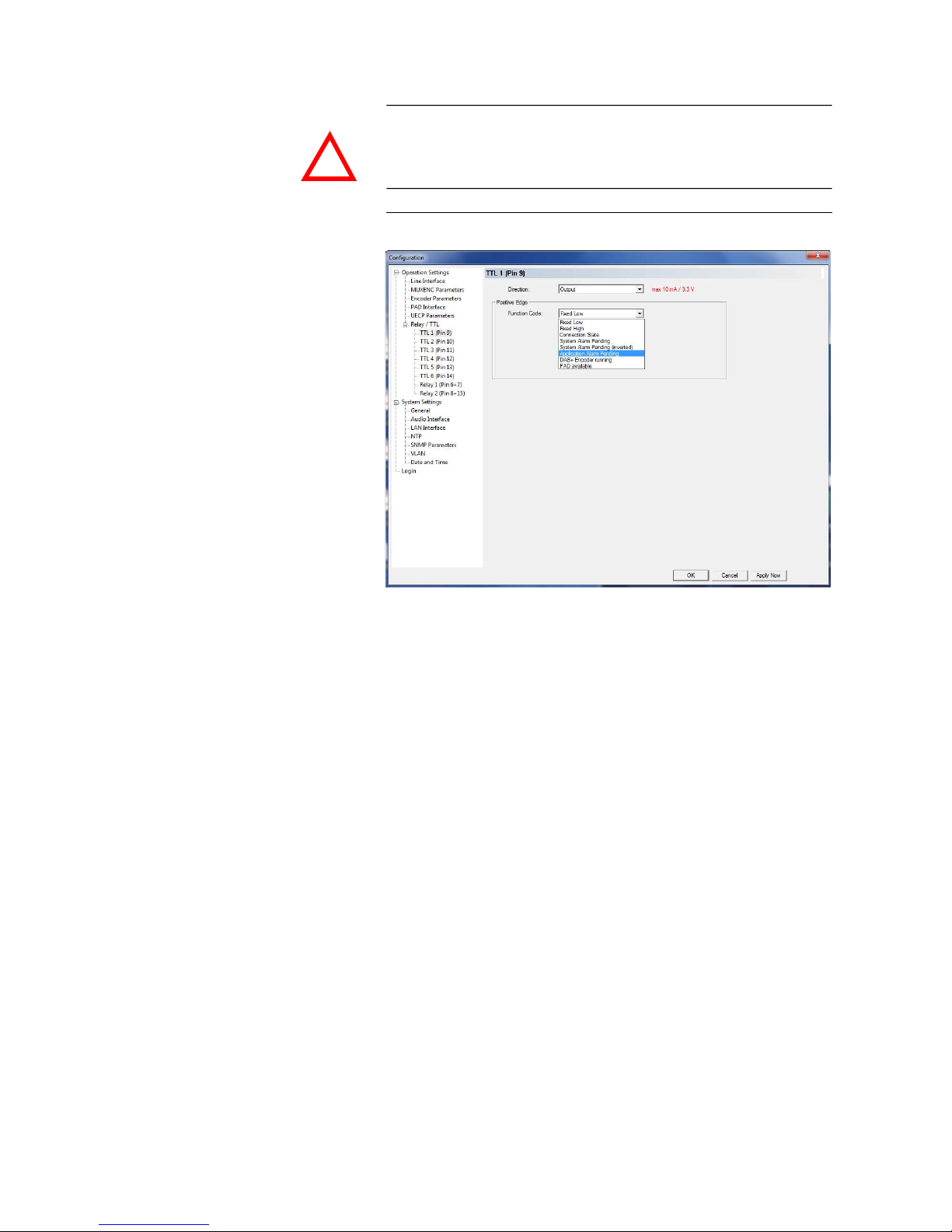
TTL Pin as Output
FIG. 30 TTL PIN AS OUTPUT
If a TTL Pin is configured as Output, the event is signalled as change of voltage on the TTL Pin from 0V to+3,3V.
Under Positive edge you can select one of the following Function Codes:
– Fixed Low: The TTL Pin is set to 0V permanently.
– Fixed High: The TTL Pin is set to +3,3V permanently.
– Connection State: Via Connection State you can signal the connection
state of a line. The following configurations are possible:
– Disconnect
– Connect
– System Alarm Pending: If one of the possible system errors (see CHAP-
TER 5.7.1) occurs, it can be astonished by selecting this option.
– System Alarm Pending (inverted): Same function as above, but output is
inverted.
– Application Alarm Pending: This function offers a signalling of applica-
tions alarms. You can combine up to three alarms:
– No Audio Level (left, right, left or right). See also the settings for the
Audio Level Alarm, Page 59.
– Encoder not running, No AES/EBU frame, Enc. not running or No
AES/EBU frame
ATTENTION Please pay attention to the maximum switch current of 10 mA respectively
the maximum switch voltage of 3,3V per TTL output.
!
Page 53

PAG E 5 3
W i n d o w s P C S o f t w a r e
– No NTP, No PAD, No PAD or NTP
– MPEG Encoder running: If the encoder detect no error, the TTL Pin will
be set.
– PAD available: If the PAD insertion is activated (see CHAPTER 5.5.2.1.4,
Page 46) and the encoder receives data the TTL Pin will be set.
Page 54
PAG E 5 4
W i n d o w s P C S o f t w a r e
Relay
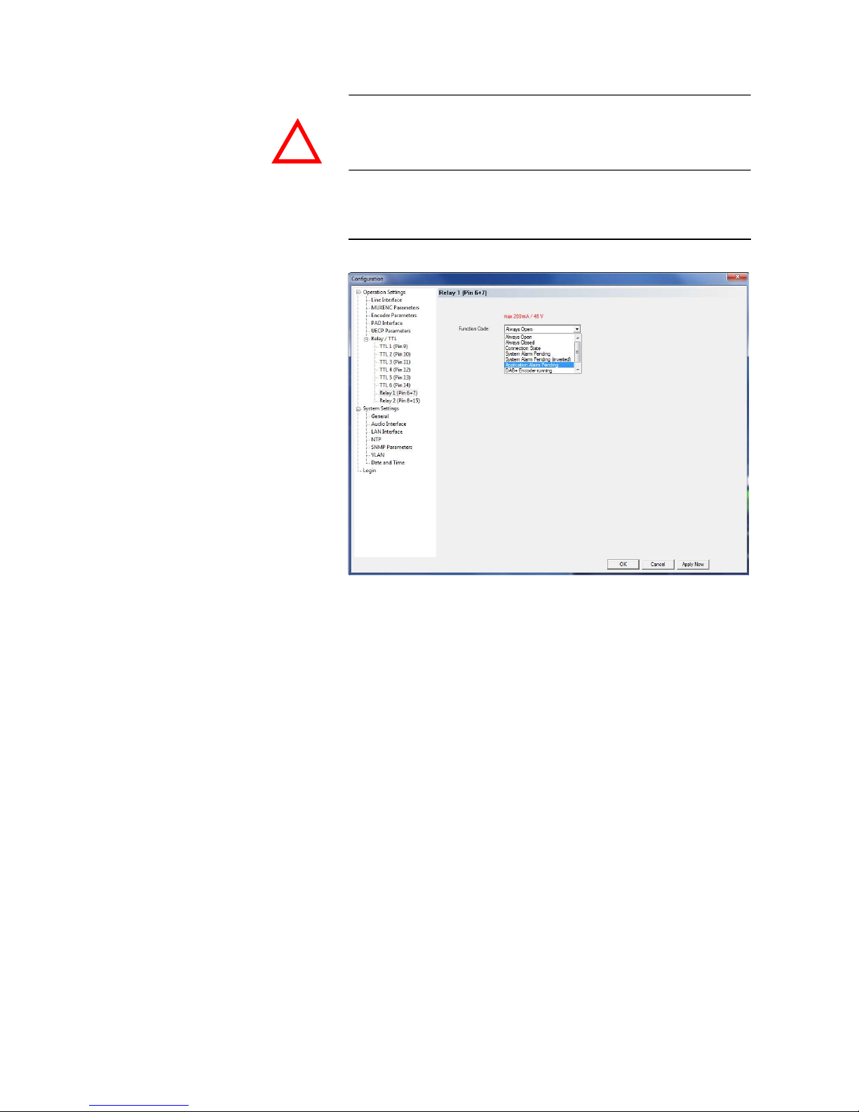
The following description applies for both configuration windows Relay 1
and Relay 2.
FIG. 31 RELAY
The options for the relay configuration are identical with the configuration of
a TTL-Pin. The following Function Codes are available:
– Always Open: The relay is always open.
– Always Closed: The relay is always closed. This can be used for example
for surveillance of the power supply.
– Connection State: Via Connection State you can signal the connection
state of a line. The following configurations are possible:
– Disconnect
– Connect
– System Alarm Pending: If one of the possible system errors (see CHAP-
TER 5.7.1) occurs, it can be signalled by selecting this option.
– System Alarm Pending (inverted): Same function as above, but output is
inverted.
– Application Alarm Pending: This function offers a signalling of applica-
tions alarms. You can combine up to three alarms:
– Audio Level (left, right, left and right). See also the settings for the Au-
dio Level Alarm, Page 59.
ATTENTION Please pay attention to the maximum switch current of 200 mA respectively
the maximum switch voltage of 48V per relay output.
!
Page 55

PAG E 5 5
W i n d o w s P C S o f t w a r e
– Encoder not running, No AES/EBU frame, Enc. not running or No
AES/EBU frame
– No NTP, No PAD, No PAD or NTP
– MPEG Encoder running: If the encoder detect no error, the relay will be
closed.
– PAD available: If the PAD insertion is activated (see CHAPTER 5.5.2.1.4,
Page 46) and the encoder receives data the relay will be closed.
Page 56
PAG E 5 6
W i n d o w s P C S o f t w a r e
5.5.2.2 System Settings
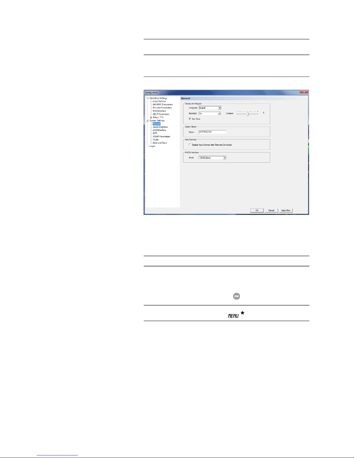
5.5.2.2.1 General
FIG. 32 GENERAL
Display and Keypad
• You can select German or English as Language for the display.
• The Display has a backlight. Under the setting Backlight you can switch
it ON permanently. If you select the option Auto off the backlight is turned
off automatically 60 seconds after the last keystroke. The backlight is activated again by pressing any key (e.g. ).
• Via the slide control Contrast you can adjust the contrast in the range -4
... 4 for the display.
• To activate the Key Tone, please tick the respective checkbox.
System Name
• The entered Name of the system will be shown in the connection list of the
MAGIC AE1 DAB+ LAN Software (see Page 37).
By entering a group name, you can summarize several Encoders in groups
(e.g. MAIN & BACKUP) for the tree view. As a separator the “-“ character
is used.
NOTE
All configurations made under System Settings cannot be saved as Preset
(see CHAPTER 5.5.3).
NOTE
The PC Software is only available in English.
NOTE
Please note that if the keypad lock is activated, the backlight is only switched
on again by pressing the key sequence .
Page 57

PAG E 5 7
W i n d o w s P C S o f t w a r e
Syntax: <Group>-<System>
The System Name consists of maximal 15 characters (A-Z, a –z and 0-9
plus the ’-’).
Auto Connect
• You can use the function Disable Auto Connect after Firmware Download to stop the Audio Encoder from re-connecting to the Multiplexer after
a firmware download. If this function is not activated, the Encoder will reestablish the connection to the Multiplexer automatically after a firmware
update.
RS232 Interface
• If you want to operate the system with the PC, you must set under Mode
the data rate in accordance with the interface of the system (see CHAPTER
5.5.1, Page 34). There are five baud rates available:
– 9600, None
– 19200, None
– 38400, None
– 57600, None
– 115200, None
Page 58
PAG E 5 8
W i n d o w s P C S o f t w a r e
5.5.2.2.2 Audio Interface
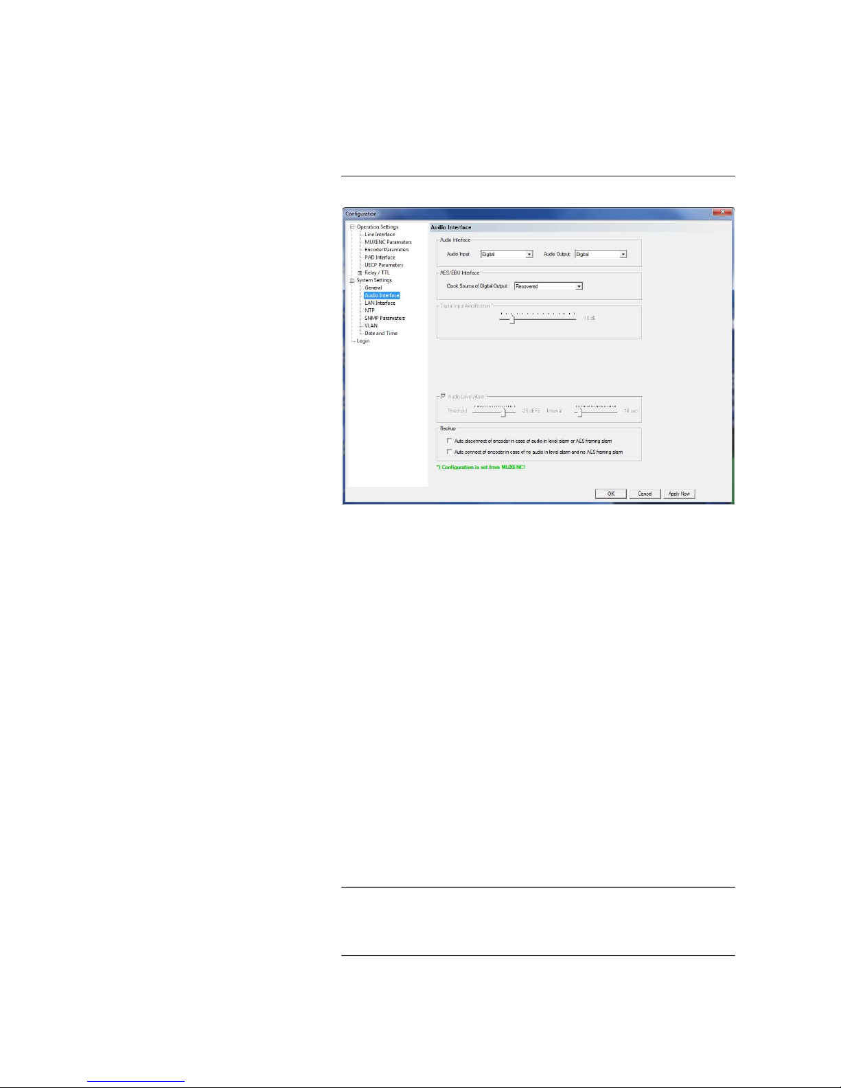
MAGIC AE1 DAB+ supports analogue as well as digital AES/EBU Audio interfaces. If the digital interfaces are used, a separate Sample Rate Converter is
available for the input and the output so that external adjustments are not required if there are different digital sources and drains.
FIG. 33 AUDIO INTERFACE
Audio Interface
• The operating mode analogue or digital can be set separately for the Audio Input and the Audio Output.
AES/EBU Interface
• If the output is set digital, additionally the configuration for the AES/EBU
Interface is displayed. Under Clock Source of digital output you can se-
lect the following options:
– Internal: The AES/EBU output clock is derived from the internal sys-
tem clock.
– External: The AES/EBU output clock is derived by the external clock
connected via the interface Audio 2/CLK IN. The clock rate of the connected clock must be 48-kHz.
– Recovered: The AES/EBU output clock is derived from the digital in-
put signal of the interface Audio 1/AES IN. This configuration is usually
to be selected if you use the digital input of the system. In this way a
synchronous functioning of the transmission chain is ensured
NOTE
The AES/EBU input always works with recovered clock, therefore only a
configuration of the output is required.
For clock synchronisation to other systems you can use the Audio output Au-
dio 2/CLK OUT. The clock rate of the output clock is 48-kHz.
Page 59

PAG E 5 9
W i n d o w s P C S o f t w a r e
Analogue/Digital Input Amplification
Here you can adjust the amplification for the Audio level of the inputs.
Main Nominal Level
• If you operate the input or the output in analogue mode, the corresponding slide control for adjusting the nominal Audio level of the Audio interface (Main Nominal Level) is displayed. The nominal level can be adjusted
separately for the input (Level In) and for the output (Level Out) in the
range of -3 ... +9 dBu in 1-dB steps.
• The Audio Headroom can be adjusted between 0...15 dBr.
Audio Level Alarm
The system has also an integrated Audio level monitor. Activate this function
by enabling the option Audio Level Alarm. With the slider Threshold you
can define the sensitivity in a range of -100...0 dBFS.
The monitoring Interval can be adjusted in a range of 0...120 seconds.
The alarm is displayed in the System Monitor (see CHAPTER 5.7.1) and can
be also defined as TTL or relay output (see CHAPTER 5.5.2.2.7).
Backup
• With the option Auto disconnect of encoder in case of audio in level
alarm or AES framing alarm the backup switching behaviour of the en-
coder can be adjusted. As soon as the encoder signals an Audio In Level
Alarm or an AES Framing Alarm, it switches to the backup encoder.
• If the checkbox Auto connect of encoder in case of no audio in level
alarm and no AES framing alarm is activated, the encoder is reactivated
when no Audio In Level Alarm and no AES Framing Alarm is detected anymore.
NOTE
If your MAGIC AE1 DAB+ Audio Encoder is connected to the MAGIC DAB MUX
Multiplexer and the MUXENC protocol is used, the Analogue/Digital Input
Amplification can be configured via the Multiplexer web interface and is
transmitted automatically to the Audio Encoder.
NOTE
If your MAGIC AE1 DAB+ Audio Encoder is connected to the MAGIC DAB MUX
Multiplexer and the MUXENC protocol is used, the Audio Level Alarm settings
can be configured in the Multiplexer and are transmitted automatically to the
Audio Encoder.
Page 60
PAG E 6 0
W i n d o w s P C S o f t w a r e
5.5.2.2.3 LAN interface
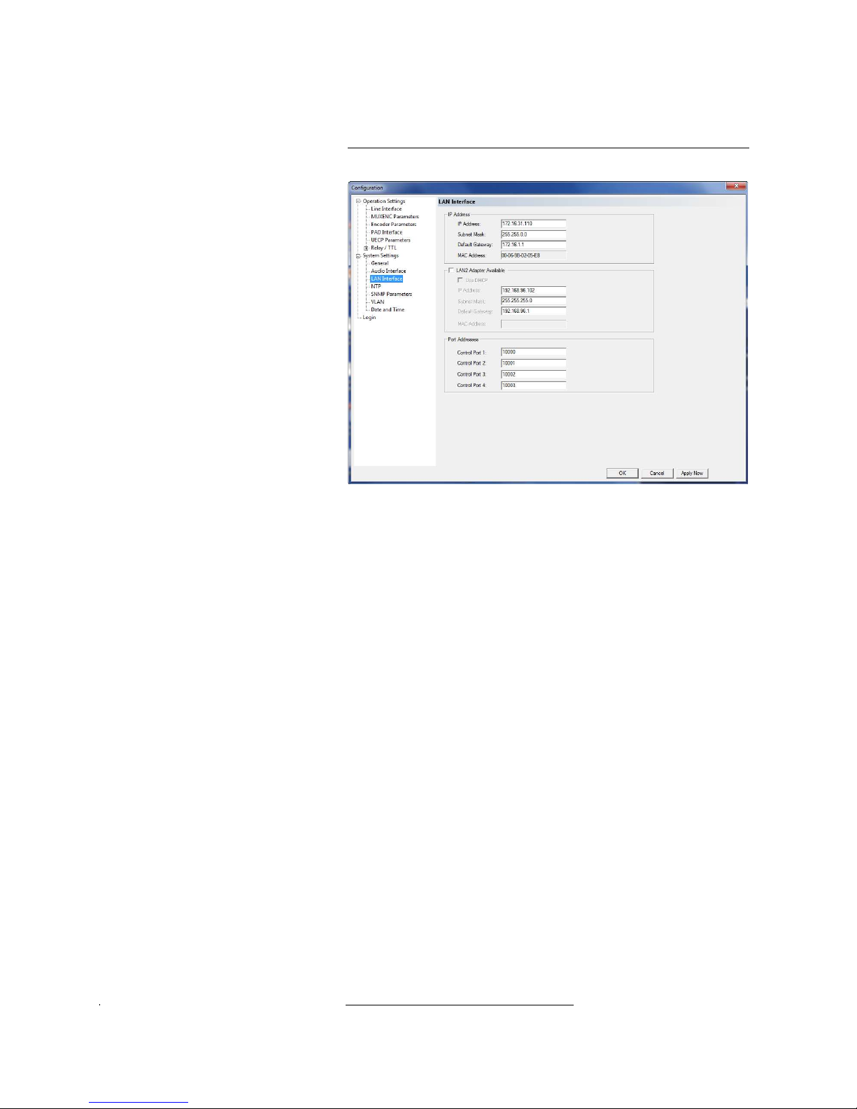
The LAN interface can be used simultaneously for the transmission of the
coded Audio signal as well as for control, PAD and monitoring.
FIG. 34 LAN INTERFACE
IP Address
• Under IP Address you have to enter the system’s local system IP address.
This IP address must be unique in your network.
1
• Enter also the correspondent Subnet Mask.
• Please enter the Default Gateway (IP address of the gateway) if the En-
semble Multiplexer is not in your local network, otherwise you can leave
this field empty.
LAN2 Adapter Available
If you have a LAN2 Adapter connected to your system or if you have an integrated second LAN interface, please mark the checkbox. The LAN2 interface
can be used for control, PAD or SNMP.
• If you are connected to a DHCP Server, you can activate the checkbox Use
DHCP to receive the correct IP parameters automatically.
• Alternatively, you can enter the IP Address, Subnet Mask and if required
the Default Gateway manually.
1
DHCP is currently not supported, but is planned for a later release.
Page 61

PAG E 6 1
W i n d o w s P C S o f t w a r e
Port Addresses
The MAGIC AE1 DAB+ Encoder can be accessed via four PCs simultaneously. In
this way, it can be monitored from 4 workplaces at the same time. At each PC
a different control port in the Control Interface settings in the PC Software.
Please note that the configuration dialogue can be opened only once at the
same time.
– Ctrl. Port 1: The default port is 10000.
– Ctrl. Port 2: The default port is 10001.
– Ctrl. Port 3: The default port is 10002.
– Ctrl. Port 4: The default port is 10003.
Page 62
PAG E 6 2
W i n d o w s P C S o f t w a r e
5.5.2.2.4 NTP
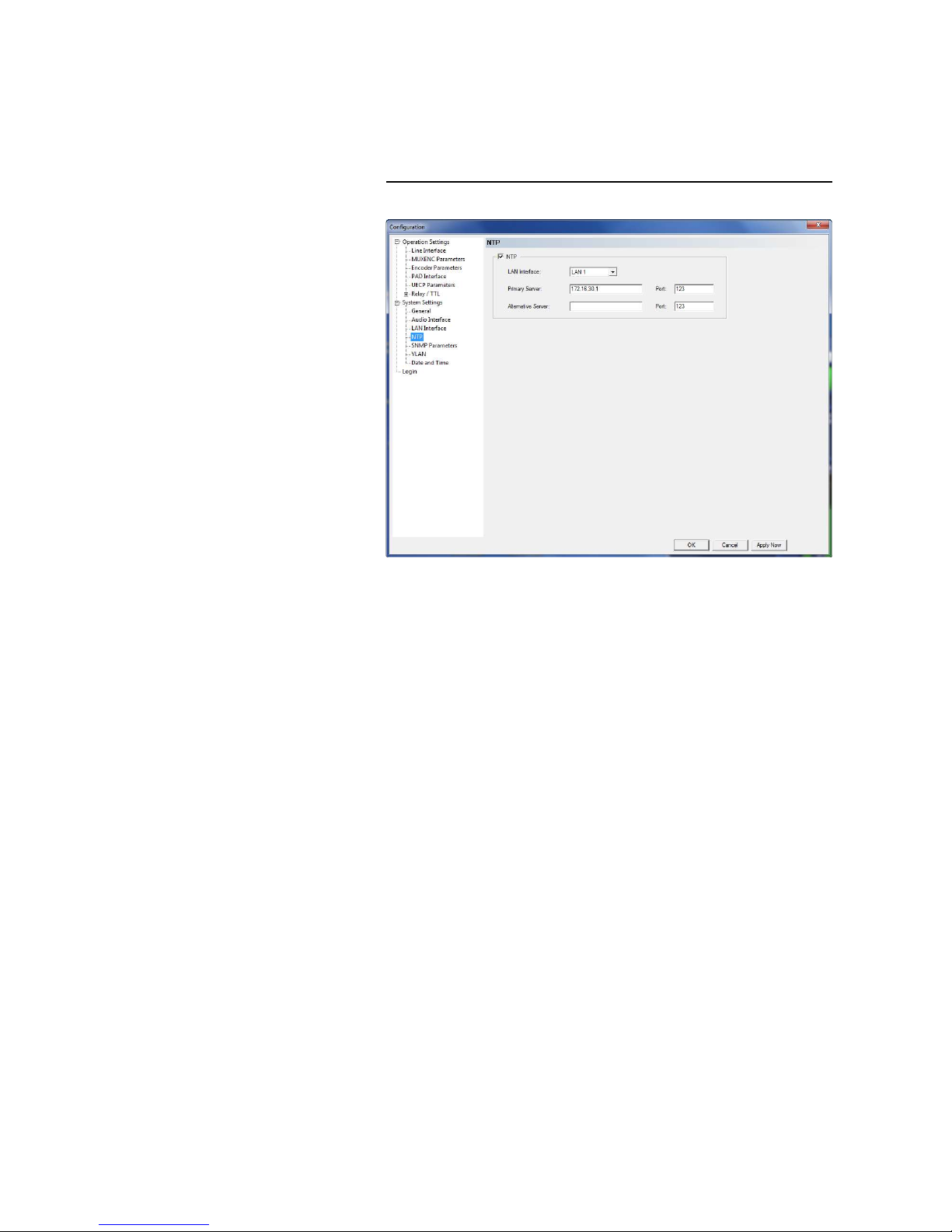
If the MAGIC AE1 DAB+ Audio Encoder is connected to a MAGIC DAB MUX Multi-
plexer, NTP is used for clock synchronisation. The parameters for the NTP
Server can be configured in this menu
FIG. 35 NTP
To use NTP please enable the NTP checkbox.
• You can enter a Primary Server and as backup an Alternative Server.
Please enter also the Port that is used.
Page 63
PAG E 6 3
W i n d o w s P C S o f t w a r e
5.5.2.2.5 SNMP Parameters
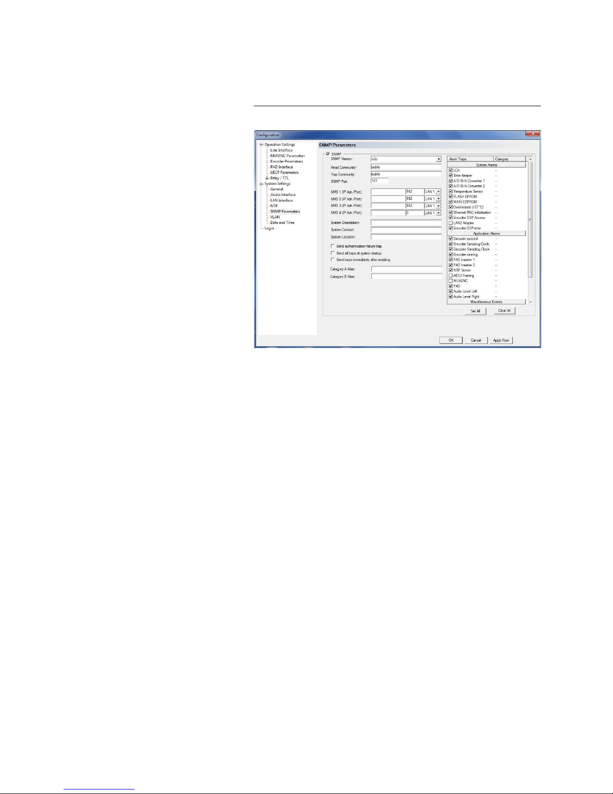
The MAGIC AE1 DAB+ Audio Encoder supports the SNMP protocol to integrate
the system into a network management system.
FIG. 36 SNMP PARAMETERS
• The SNMP function is enabled when you mark the box SNMP.
• Please select under SNMP Version if you are using SNMP v1 or v2c.
• The Read Community entry is an identifier to read data. The name has to
be identical with the name in your Management System. By default, the
name public is used.
• Under Trap Community you define the name for the trap datagrams. The
name has to be identical with the name in your Management System.
• Please enter the port on which MAGIC AE1 DAB+ System receives messages
under SNMP Port. The default setting is 161.
• MAGIC AE1 DAB+ allows the addressing of up to four different Network
Management Systems. Please enter the corresponding IP addresses and
Ports under NMS 1 (IP Adr./Port), NMS 2 (IP Adr./Port), NMS 3 (IP
Adr./Port) and NMS 4 (IP Adr./Port).
• Under System Description you can assign a name for the system.
• Under Contact an email address can be entered.
• In the entry field System Location you can write the location of the Audio
Encoder.
• You can enable the option Send authentication failure trap to send the
authentication failure trap. This happens when the system detects a access
trial with a wrong community string.
Page 64
PAG E 6 4
W i n d o w s P C S o f t w a r e
• With the option Send all traps at system startup the system sends all
traps after the system has booted. In this way the system status can be easily checked via SNMP.
• With the option Send traps immediately after enabling the system sends
the activated traps immediately after they have been selected.
• Under Alarm Traps you can select which traps should be sent via SNMP.
You can also activate several Application Alarms and Miscellaneous
Events to be sent via SNMP. To enable all listed traps, alarms and events
you can press the Set All button. Via the Clear All button the selection will
be cleared.
• Under Category you can assign the traps to Category A or Category B.
If you do not want to use a category, you can select No category. Under
Miscellaneous Events you can also select that you would like to receive
all traps marked with Category A or Category B.
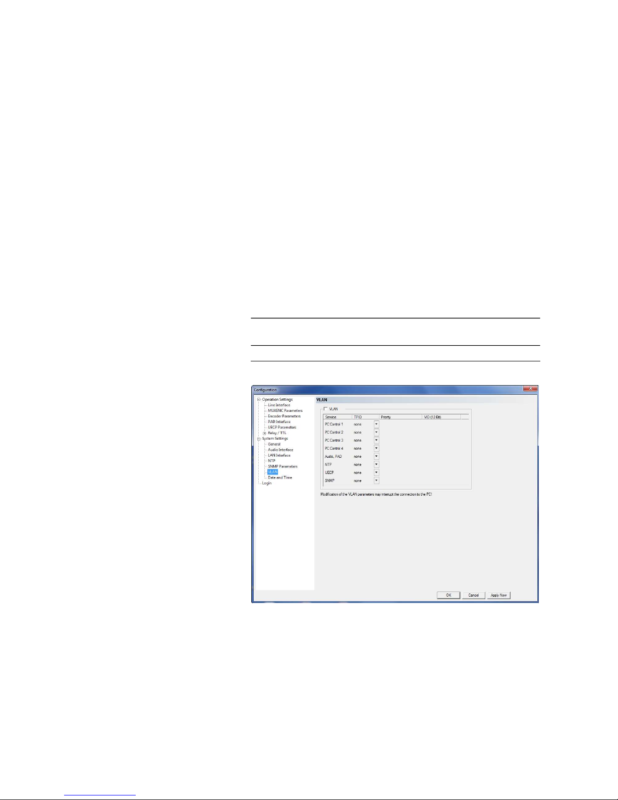
5.5.2.2.6 VLAN
MAGIC AE1 DAB+ supports the VLAN (Virtual LAN) feature. In this way,
separate virtual networks can be defined for different services (e.g. PC control, Audio/PAD) and each of these networks can have a different priority.
FIG. 37 VLAN
To activate VLAN, simply mark the respective checkbox.
• Now you can select for each Service for which you want to use VLAN the
802.1Q Tag under TPID.
• Under Priority you can define the priority level from 0 (Default, Best Ef-
fort) to 7 (Network Control).
NOTE
Please make sure that your network switches also support VLAN if you want
to use this feature.
Page 65
PAG E 6 5
W i n d o w s P C S o f t w a r e
• Under VID you must enter the correct VLAN ID which you usually get
from your network administrator.
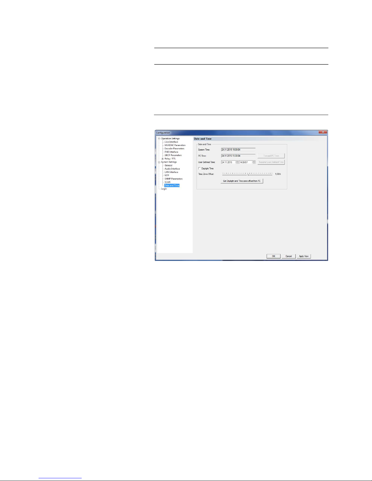
5.5.2.2.7 Date and Time
Via the panel Date and Time it is possible set the internal clock of the system.
FIG. 38 DATE AND TIME
• To synchronise the System Time to the PC Time press the button Transmit PC Time.
• To setup another time e.g. for other time zones you can enter a User Defined Time. To set the time in the system press the button Transmit User
Defined Time.
• Please activate the checkbox Daylight Time if you want to use daylight
time.
• Here you can enter the Time Zone Offset for your local time.
• It is also possible to activate the option Get Daylight and Time Zone Off-
set from PC to receive these settings from your PC.
NOTE
Please note that a modification of the VLAN parameters may interrupt the
connection to your PC.
Page 66
PAG E 6 6
W i n d o w s P C S o f t w a r e
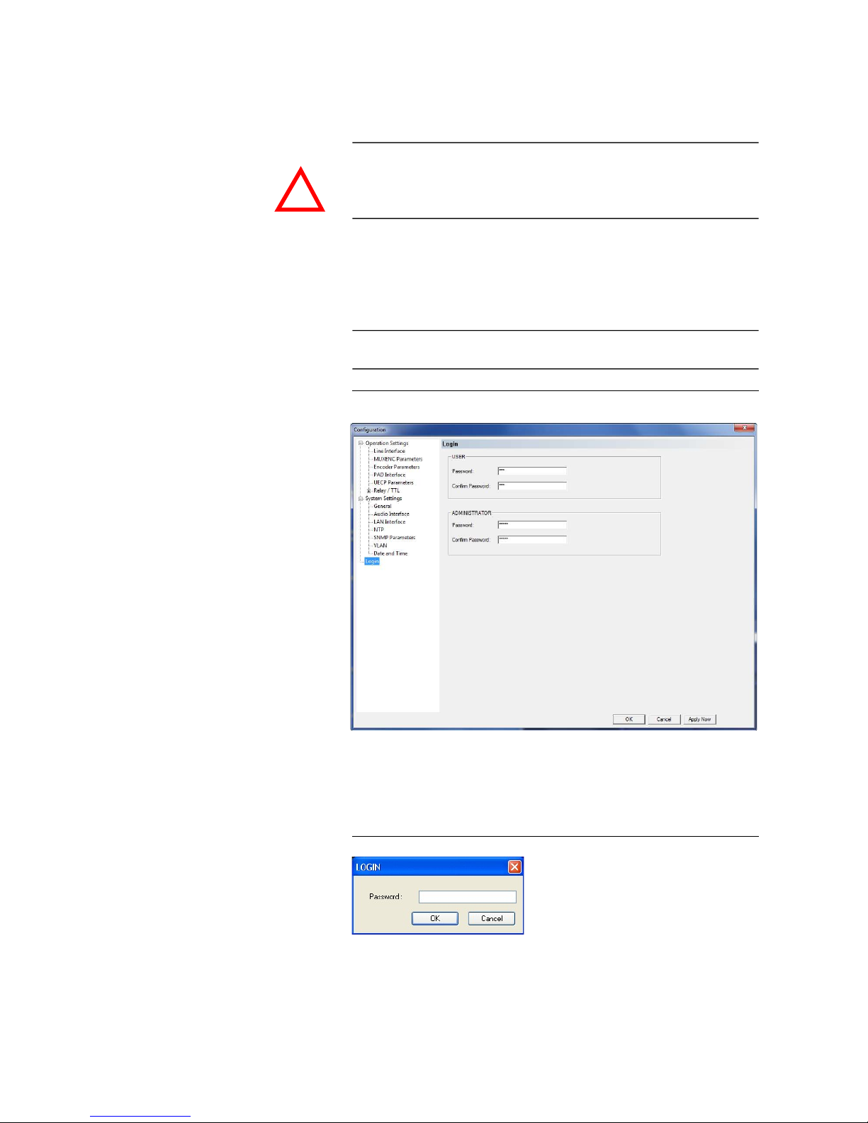
5.5.2.3 Login
To protect the system from re-configurations, two password levels with different user rights are available.
• Under USER you assign the user Password. For safety reasons you must
confirm the password under Confirm Password.
• Under ADMINISTRATOR you assign the Administrator Password. For
safety reasons you must confirm the password under Confirm Password.
FIG. 39 LOGIN
When you have assigned a password, the window for the password entry is
automatically displayed when you click on a menu with password protection.
Please enter the User Password or the Administrator Password.
FIG. 40 PASSWORD LOGIN
The authorisation levels are defined as follows:
(1) Only Administrator Password is configured: The password must be en-
tered for configuration changes. Immediately available menus:
ATTENTION The entered password is saved in the system. It is highly important that you
enter your password carefully. If you have forgotten your password, only the
AVT Service can re-activate the system.
NOTE
There is no differentiation between upper and lower case for the password
entry.
!
Page 67

PAG E 6 7
W i n d o w s P C S o f t w a r e
– File Operation Settings Presets Export
– File System Settings Export
– Configuration Presets „Configuration Name“
– Administration Registration
– Extras System Monitor
– Help About MAGIC AE1 DAB+
(2) Only User Password is configured: The password must be entered al-
ways. Afterwards all menus are available. Immediately available
menus:
– Help About MAGIC AE1 DAB+
(3) User Password and Administrator Password are configured: The pass-
word must always be entered.
User Password is entered:
Under Configuration Configuration Login the USER pass-
word can now be changed.
Via Configuration Presets the desired configuration can be
loaded.
Immediately available menus:
– Extras System Monitor
Administrator Password is entered: All menus are available.
NOTE
Please pay attention to the configuration options of the system if a password
is assigned (see CHAPTER A1).
Page 68
PAG E 6 8
W i n d o w s P C S o f t w a r e
5.5.3 Submenu Presets
Via Presets you can load already created configurations.
FIG. 41 SELECTION OF A PRESET
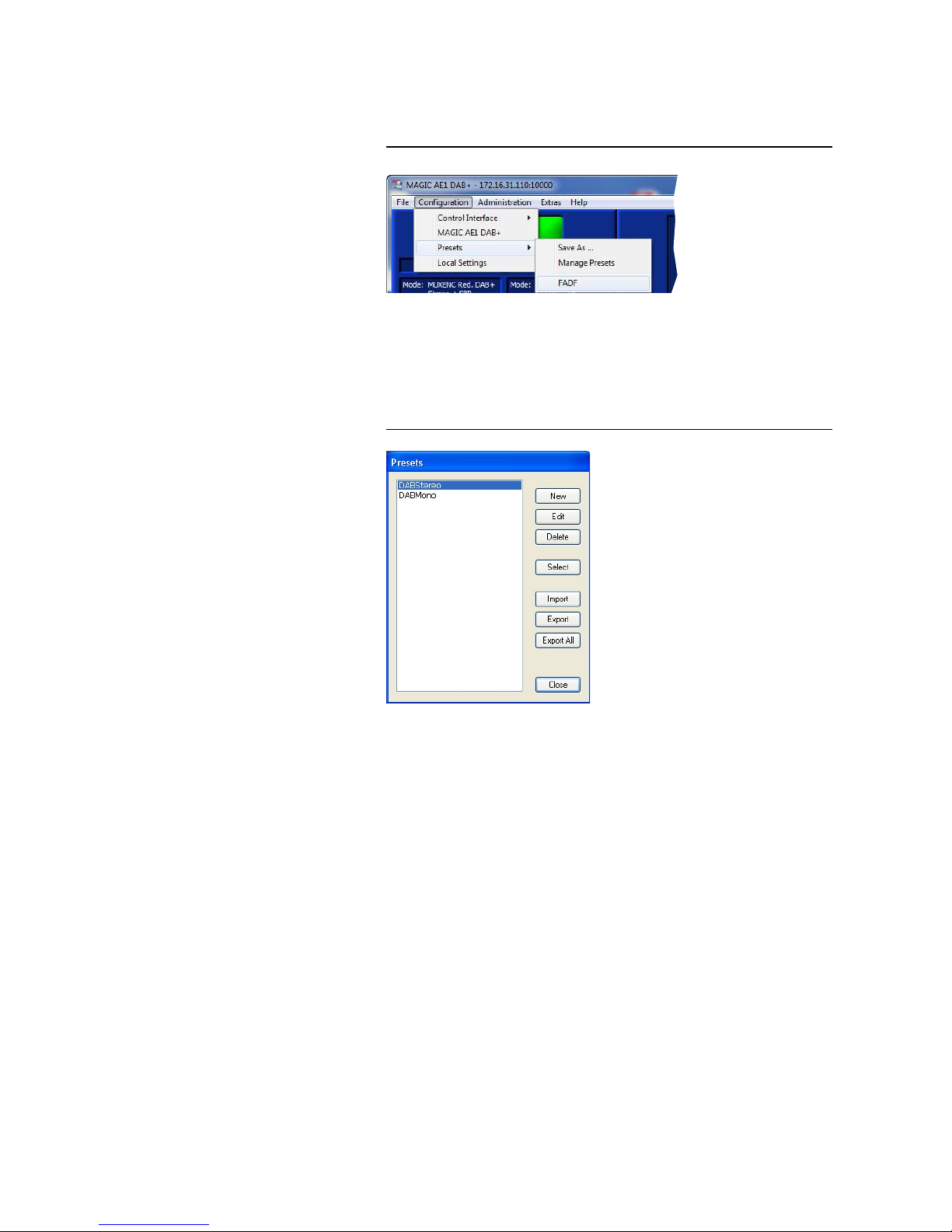
5.5.3.1 Manage Presets
Your created Presets can be managed via the menu Configuration Pre-
sets Manage Presets.
FIG. 42 MANAGE PRESETS
All already existing configurations are displayed in the list.
• With the use of the New button you create a new configuration. The current configuration of the system is not changed or loaded by this function.
First, select an expedient name. The length of the name must not surpass 8
characters. Special characters and space characters are not allowed. Please
mind that you use unique names.
Subsequently, the configuration dialogue is opened for the editing of the
Presets. The current configuration is always displayed as basis of a Preset which you can adjust according to your wishes. The following config-
urations can be saved as Preset:
– Line interface (see Page 40)
– MUXENC Parameters (see Page 42)
– Encoder Parameters (see Page 44)
– PAD Interface (see Page 46)
– UECP Parameters (see Page 48)
– Relay/TTL (see Page 50)
Page 69

PAG E 6 9
W i n d o w s P C S o f t w a r e
• By using the button Edit the currently selected configuration can be ed-
ited. The current configuration of the system is not changed or loaded with
this function.
• Via the button Delete the configuration selected from the list is deleted.
For safety reasons you have to confirm your selection.
• To activate a configuration selected from the list, press the Select button.
For safety reasons you have to confirm your selection.
• Via the button Import a configuration can be imported from a data carrier
(disk, USB stick etc.). The file extension of the configuration file is always
‘.pst‘. A click on the button opens the file browser in which the desired file
can be selected.
• Likewise, it is possible to export configurations to a data carrier. The but-
ton Export saves the configuration selected from the list as ‘.pst‘ file. By
clicking on the button the file browser is opened and you can choose the
location where the file is saved.
With Export All all configurations displayed in the list are saved in a directory of your choice. A separate data file with the file extension ’.pst‘ is
generated for each configuration.
5.5.3.2 Activation of a Preset
All Presets are displayed under Configuration Presets „Preset
Name“ and can be activated with a click.
For safety reasons a confirmation is required.
TIP
If you need to configure several systems in the same way, set up one system
first and export all configurations to a disk. To configure all further systems
easily, import the configurations from the disk.
This is also possible for the System Settings. Via the Import/Export function
under File (see CHAPTER 5.4) you can comfortably save all information and
load on other systems.
Page 70
PAG E 7 0
W i n d o w s P C S o f t w a r e
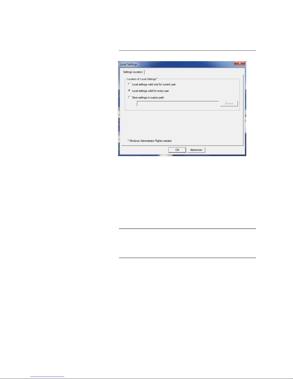
5.5.4 Submenu Local Settings
Under this submenu you can configure the storage location for the local settings.
FIG. 43 LOCAL SETTINGS
Settings Location
• To store your settings only for the current user, select the option Local settings only valid for current user.
• To store the settings globally for all users, select the option Local settings
valid for every user.
• Alternatively, you can select the option Store settings in custom path to
define a specific folder in which your settings are stored.
NOTE
You need Windows administrator rights to change the storage location of the
local settings.
Depending on the storage location, you might have to start the Windows PC
Software with administrator rights to make changes in the configuration.
Page 71
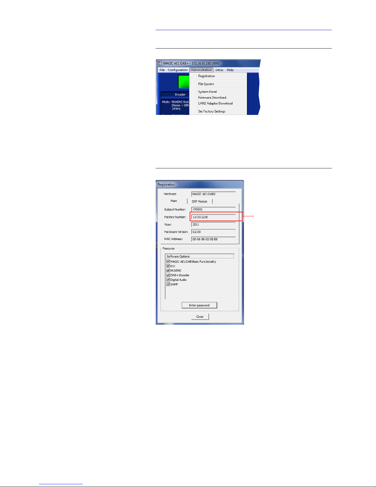
PAG E 7 1
W i n d o w s P C S o f t w a r e
5.6 Menu Administration
FIG. 44 MENU ADMINISTRATION
5.6.1 Submenu Registration
The system’s production data as well as the enabled options can be displayed
under the submenu Registration.
FIG. 45 SUBMENU REGISTRATION
The data of the unit include the following information:
– Hardware
– Subject Number
– Factory Number
– Year of production
– Hardware Version
– MAC Address
This number
is required
to enable
software options
supplementarily
Page 72
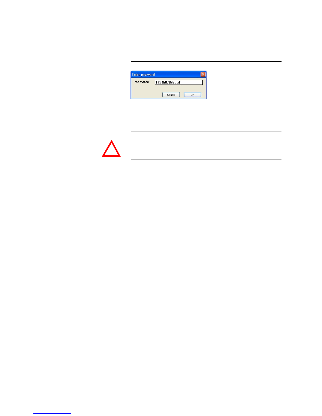
PAG E 7 2
W i n d o w s P C S o f t w a r e
• Under Features the available and activated Software Options of the
MAGIC AE1 DAB+ are displayed. Deactivated options can be activated via a
password. This password is assigned according to the Factory Number. If
you bought an option supplementarily, please enter the password that you
received from us under Enter Password.
FIG. 46 PASSWORD ENTRY TO ENABLE AN OPTION
Subsequently, the system executes a warm start. Afterwards, the functions are
activated.
ATTENTION Please enter the password carefully.
If you enter a wrong password three times, you must switch off the system
and switch it on again.
!
Page 73
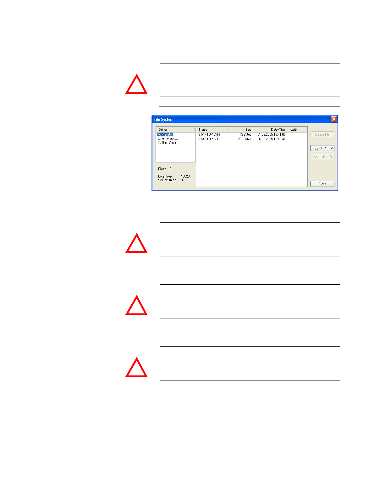
PAG E 7 3
W i n d o w s P C S o f t w a r e
5.6.2 Submenu File System
Selecting the submenu File System the storage system (similar to a PC’s hard
drive) of the system is displayed.
FIG. 47 SUBMENU FILE SYSTEM
• The button Delete File deletes the currently selected file from the system.
• Via the button Copy PC -> Unit you can copy a file from the PC to the sys-
tem.
• Via the button Copy Unit -> PC you can copy a file from the system to the
PC.
ATTENTION Please do not use the File System unless our Service requested a specific ac-
tion.
ATTENTION Please do not delete any file unless our Service requested a specific action.
Otherwise a disfunction of the system is possible.
ATTENTION Please use the Software Download and the File Import functionalities respec-
tively to copy files to the system.
ATTENTION Please use the File Export functionalities to copy files to the PC.
!
!
!
!
Page 74
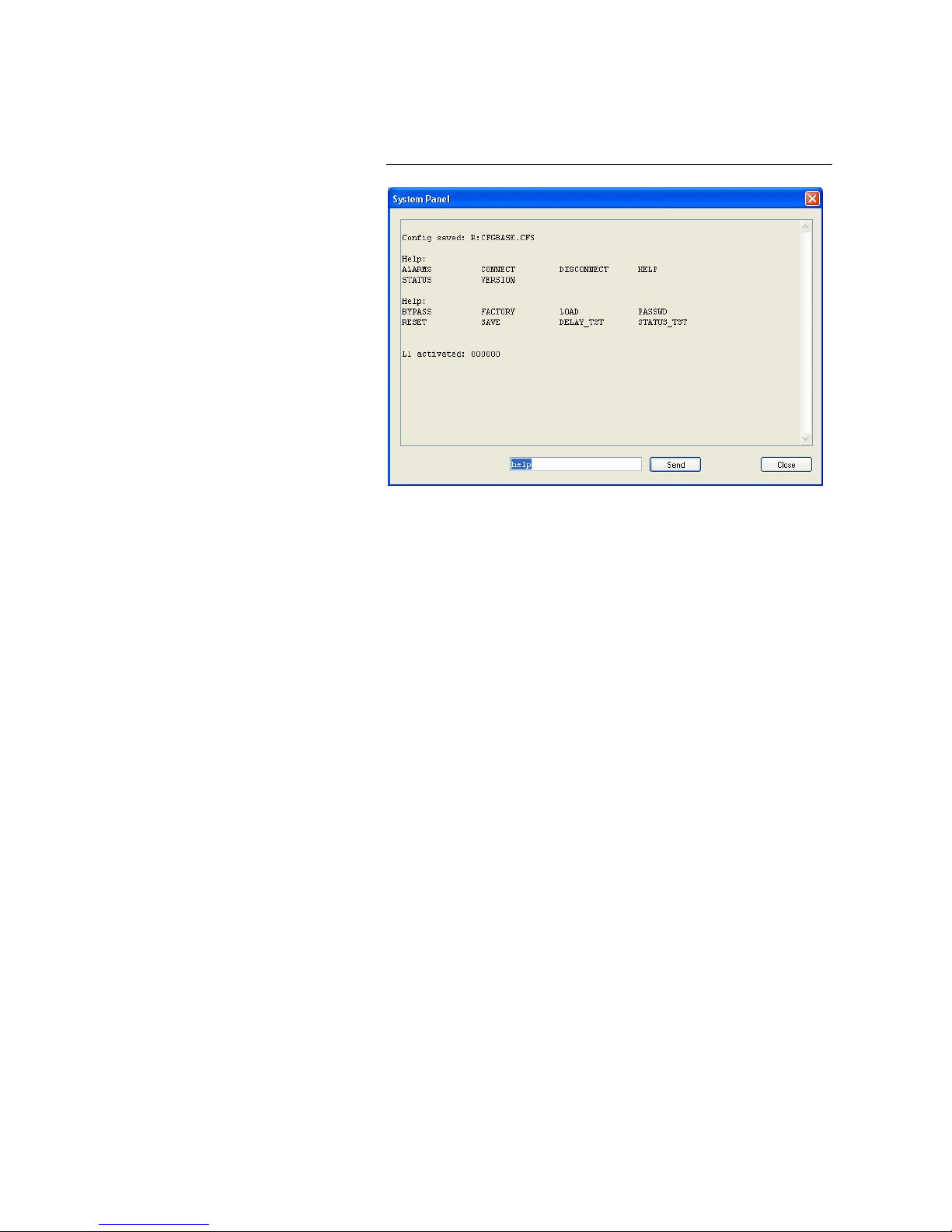
PAG E 7 4
W i n d o w s P C S o f t w a r e
5.6.3 Submenu System Panel
The System Panel is only for service purposes. Please enter only commands
in the prompt, if our Support requested it from you.
FIG. 48 SUBMENU SYSTEM PANEL
Page 75
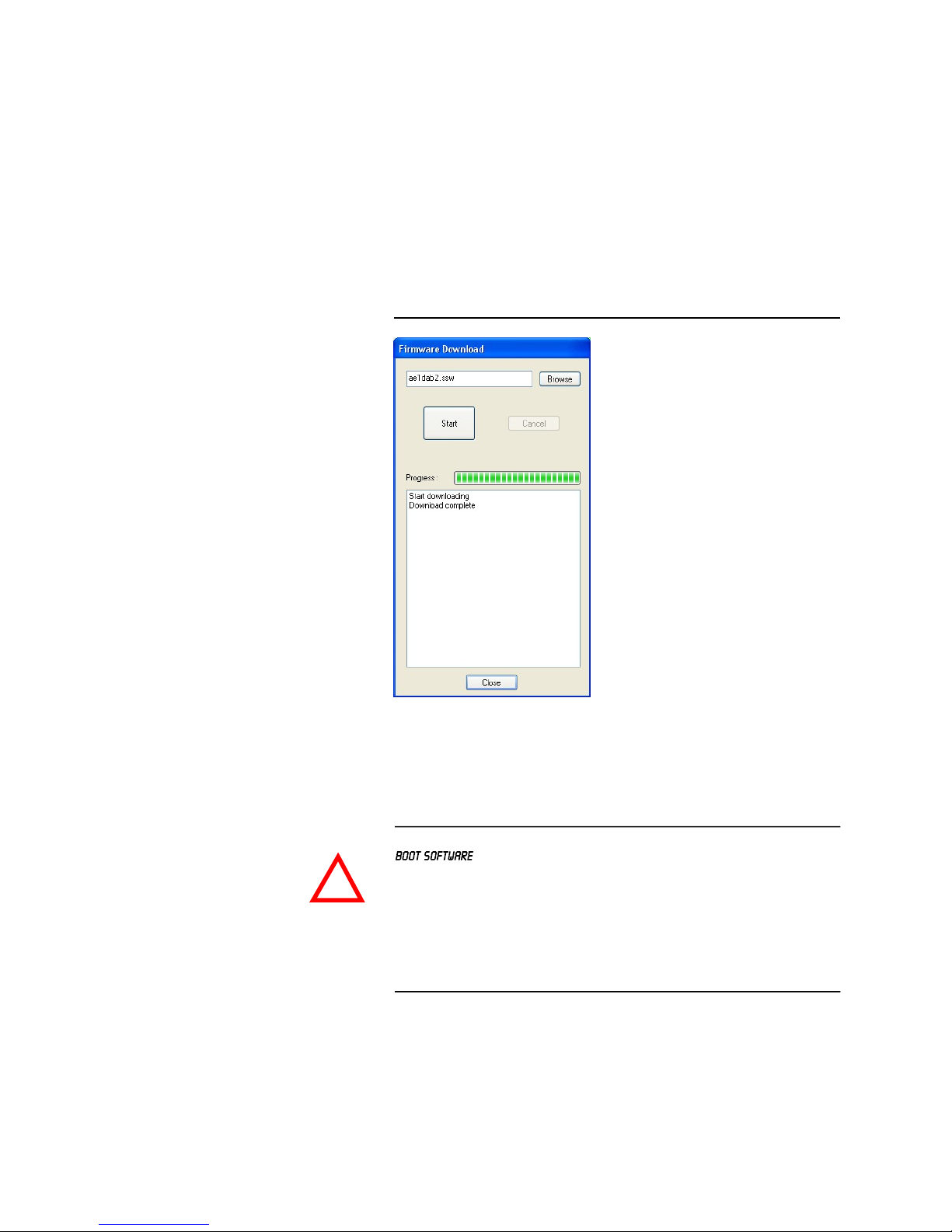
PAG E 7 5
W i n d o w s P C S o f t w a r e
5.6.4 Submenu Firmware Download
The required firmware for the MAGIC AE1 DAB+ system is always included in
the PC software: Via the Firmware Download you can comfortably download the firmware on your system.
By using the Browse button you select the firmware file. It is always located
in the same directory in which you installed the MAGIC AE1 DAB+ application.
The standard installation directory is:
C:\Program Files\MAGIC AE1 DAB
The file name of the firmware is „ae1dab2.ssw“.
FIG. 49 SUBMENU FIRMWARE DOWNLOAD
Please press the Start button to download the firmware. The Progress bar
displays the progress of the download. The process is finished after about two
minutes. If the download was successful, a corresponding message is displayed. After your confirmation the system is reset.
ATTENTION If the download was not successful, you will see in the display the message
.
In this case you must use the RS232 interface to download the software again.
If you are using the LAN interface you must change your settings in the PC
software to the following values (see also Page 35, Using the LAN interface):
– IP Address: 192.168.96.102
– Port: 10000
These LAN settings are already stored in the boot eprom which guarantees
that you will get a connection to the system via IP.
!
Page 76
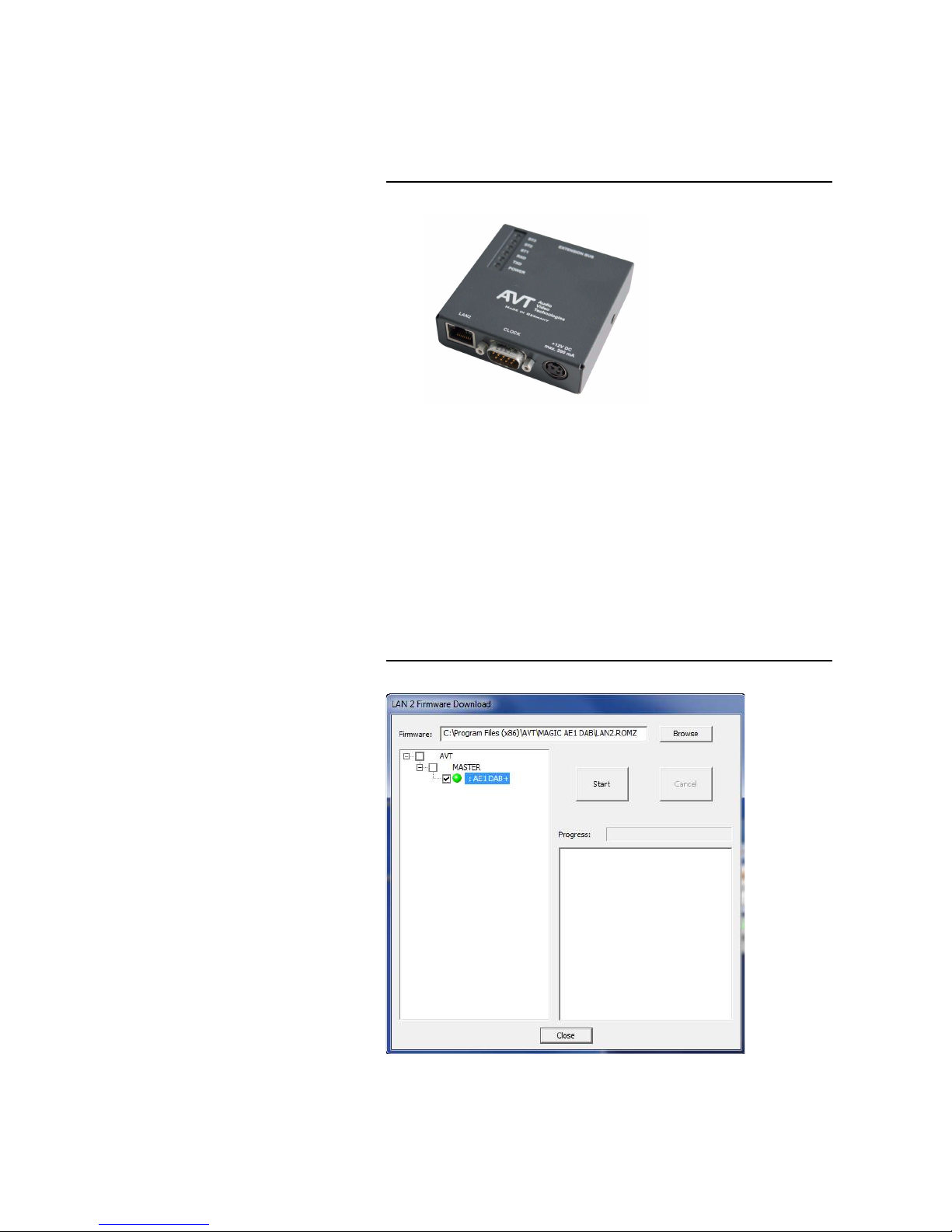
PAG E 7 6
W i n d o w s P C S o f t w a r e
5.6.5 Submenu LAN2 Adapter Download
If your system has been extended with the LAN2 Adapter (external adapter
or integrated 2nd LAN interface), you can execute a firmware download for
the LAN2 Adapter via this submenu if necessary.
FIG. 50 EXTERNAL LAN2 ADAPTER
The required firmware for the LAN2 Adapter of the MAGIC AE1 DAB+ is always
included in the PC software: Via the LAN2 Adapter Download you can com-
fortably download the firmware on your adapter.
By using the Browse button you select the firmware file. It is always located
in the same directory in which you installed the MAGIC AE1 DAB+ application.
The standard installation directory is:
C:\Program Files\MAGIC AE1 DAB
The file name of the firmware is „lan2.romz“
FIG. 51 LAN2 ADAPTER DOWNLOAD
Page 77

PAG E 7 7
W i n d o w s P C S o f t w a r e
Please select the system for which you want to update the LAN2 Adapter
firmware on the left side. Now press the Start button to download the
firmware. The Progress bar displays the progress of the download. The proc-
ess is finished after about one minute. If the download was successful, a corresponding message is displayed.
Page 78

PAG E 7 8
W i n d o w s P C S o f t w a r e
5.6.6 Submenu Set Factory Settings
By using the submenu Set Factory Settings the system can be reset to the in-
itial state.
For safety reasons you have to confirm your selection.
Page 79
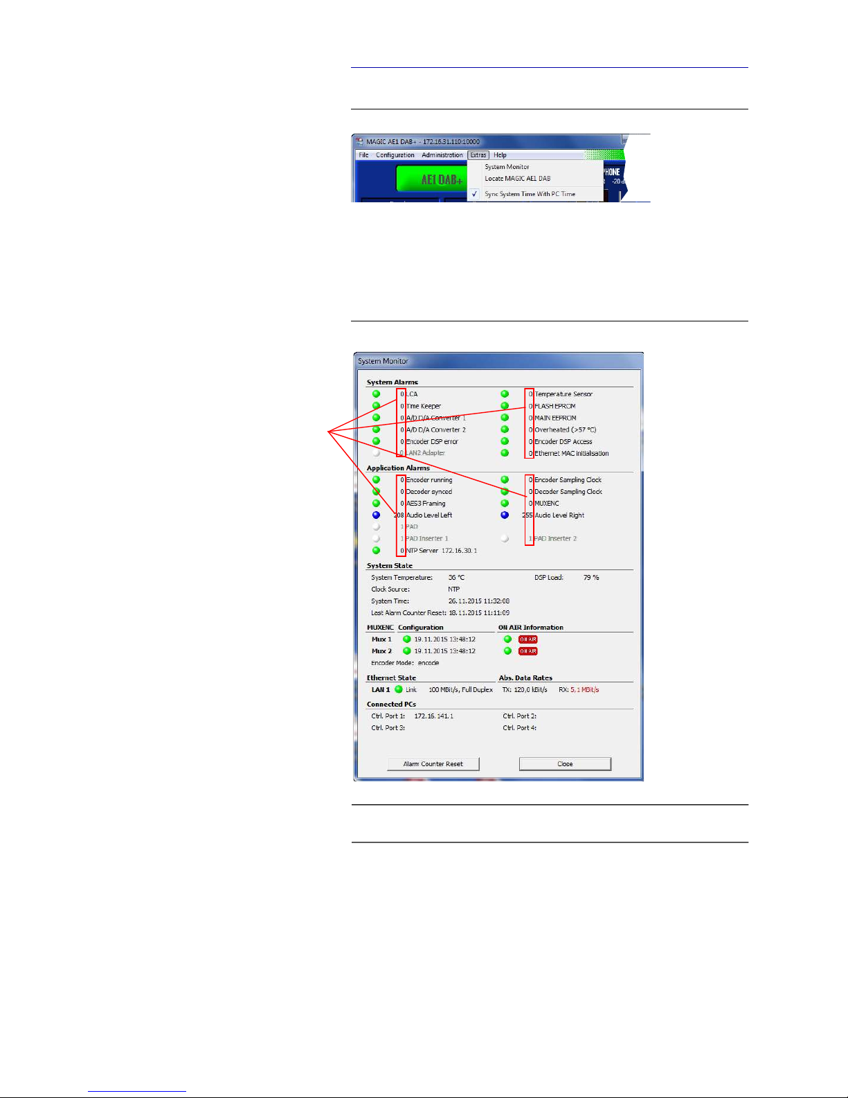
PAG E 7 9
W i n d o w s P C S o f t w a r e
5.7 Menu Extras
FIG. 52 MENU EXTRAS
5.7.1 Submenu System Monitor
Via the menu System Monitor you receive information about the system sta-
tus.
FIG. 53 SUBMENU SYSTEM MONITOR
A red LED signals a currently existing alarm. A blue LED shows that an alarm
has occurred but is no longer active. How often the alarm occurred since
switching on is displayed by the corresponding error counter. A green LED
means no current alarm.
TIP
An alarm can also be configured as TTL (see Page 50) or relay output (see
Page 54).
Error Counter
Page 80

PAG E 8 0
W i n d o w s P C S o f t w a r e
To reset all error counter press the button Alarm Counter Reset.
System alarms
• Under System alarms all potential system alarms are displayed:
– LCA: The communication with a programmable component is faulty.
– Time Keeper: The communication with the integrated clock module is
faulty.
– A/D D/A Converter 1: The communication with the first ADDA con-
verter is faulty.
– A/D D/A Converter 2: The communication with the second ADDA con-
verter is faulty.
– Temperature Sensor: The communication with the temperature sen-
sor is faulty.
– FLASH EPROM: The communication with the permanent memory is
faulty. Configurations cannot be saved or read anymore.
– MAIN EEPROM: The communication with the permanent memory is
faulty. Configurations cannot be saved or read anymore.
– Overheated: The system sets this alarm if the system temperature is
higher than 57°C. Disconnect the unit from electricity or cool down the
ambient temperature.
– Encoder DSP error: This alarm occurs if an error on the DSP module
is detected.
– Encoder DSP Access: This alarm occurs if the Encoder cannot access
the DSP module.
– LAN2 Adapter (only if the systems has a LAN2 Adapter): The LAN2
Adapter is not working properly.
– Ethernet MAC initialisation: The initialization of the ethernet module
has failed.
Application Alarms
• Under Application alarms all codec alarms are centralised:
– Encoder running: If the encoder is not running, this alarm will be set.
– Encoder sampling clock: This alarm occurs if the hardware sampling
clock do not fit with the expected sampling clock of the encoder.
– Decoder synced: For monitoring purposes the coded signal is de-
coded at any time via the integrated DAB+ decoder. If the Decoder is
not synced, the corresponding alarm is set.
– Decoder sampling clock: This alarm occurs if the hardware sampling
clock do not fit with the expected sampling clock of the decoder.
– AES3 Framing: If the digital Audio interface is configured, but no sig-
nal is received, the AES3 Framing Alarm is signalled.
NOTE
If an alarm occurs frequently or over a longer period disconnect the unit from
electricity. If the error occurs again after switching on, there is probably a
hardware defect.
Page 81

PAG E 8 1
W i n d o w s P C S o f t w a r e
– MUXENC: The MUXENC protocol transmits the control and ON AIR
information from Multiplexer to Encoder. If one of this information is
missing, the systems sets an alarm.
– Audio level left: This alarm occurs if the left audio input level is during
the configured time interval lower than the configured threshold (see
Page 59, Audio Level Alarm).
– Audio level right: This alarm occurs if the right audio input level is
during the configured time interval lower than the configured thresh-
old (see Page 59, Audio Level Alarm).
– PAD: If PAD is activated, but no data is inserted at the PAD interface
e.g. because the frame counter does not match, this alarm will be set.
The threshold value can be defined in the PAD configuration menu under PAD Alarm Timeout (see Page 46).
In addition to the alarm LED, the IP address and Port of the connected
PAD Server are displayed.
– PAD Inserter 1: This alarm is set if no PAD is received from the PAD
Inserter 1 although PAD is activated. The threshold value can be defined in the PAD configuration menu under PAD Alarm Timeout (see
Page 46).
– PAD Inserter 2: This alarm is set if no PAD is received from the PAD
Inserter 2 although PAD is activated. The threshold value can be defined in the PAD configuration menu under PAD Alarm Timeout (see
Page 46).
– NTP Server: This alarm shows you if the connection with the NTP
Server is ok. You can also see here the IP address of NTP Server.
System State
• The actual system temperature is displayed in °C under System Temper-
ature. The regular system temperature ranges from 30...45°C.
• Under DSP Load the load of the system is displayed. The usual load is
about 40 to 65%.
• Under Clock Source the selected clock source, e.g. NTP, is displayed.
• The System Time shows the date and the time in hh:mm:ss.
• The Last Alarm Counter Reset informs you when the alarm counter has
been reset the last time.
MUXENC Configuration
• If the Encoder is connected with a MAGIC DAB MUX Multiplexer or an FhG
Content ServerTM and uses the MUXENC protocol, the connection status of
the main Multiplexer and optional redundant Multiplexer are displayed
here.
• The date and time of the last (re-)configuration of the Multiplexer is dis-
played under Configuration.
TIP
If a MAGIC MUX DAB Multiplexer is connected to the MAGIC AE1 DAB+ system,
the Multiplexer can be used also as PAD Server.
Page 82

PAG E 8 2
W i n d o w s P C S o f t w a r e
ON AIR Configuration
• Here you can see here if the Encoder is marked as ON AIR Encoder ,
inactive Encoder (e.g. Backup Encoder) or deactivated Encoder
in the configuration of the main and backup MAGIC DAB MUX Mul-
tiplexer.
Ethernet State
• The Link LED shows if the LAN 1 connection and optionally the LAN 2
connection is ok. Here you find also some information on the connected
network.
Abs. Data Rates
• Here you can see the absolute data rates in TX (transmit) direction and RX
(receive) direction.
Connected PCs
• Up to four PCs can be connected simultaneously to the MAGIC AE1 DAB+
Audio Encoder. The IP addresses of the currently connected PCs are dis-
played under Ctrl. Port 1...4. It is also indicated if the configuration dialogue is opened at one of the connected PCs.
NOTE
The value for the RX direction is displayed in red as soon as it exceeds 500
kbit/s. Usually, we expect a lower value since only PAD and control data is
received.
In case of a higher bit rate it is likely that something is wrong with your network configuration.
Page 83

PAG E 8 3
W i n d o w s P C S o f t w a r e
5.7.2 Submenu Locate MAGIC AE1 DAB
This submenu can help you to locate the system to which you are currently
connected if you have several MAGIC AE1 DAB+ Encoders installed in a rack.
By clicking on the submenu, the display of the respective system is blinking
five times.
5.7.3 Sync System Time With PC Time
With this function you can sync the time of the MAGIC AE1 DAB+ system
with your PC time. If you see a checkmark, the system time is synced already
with your PC time.
Page 84
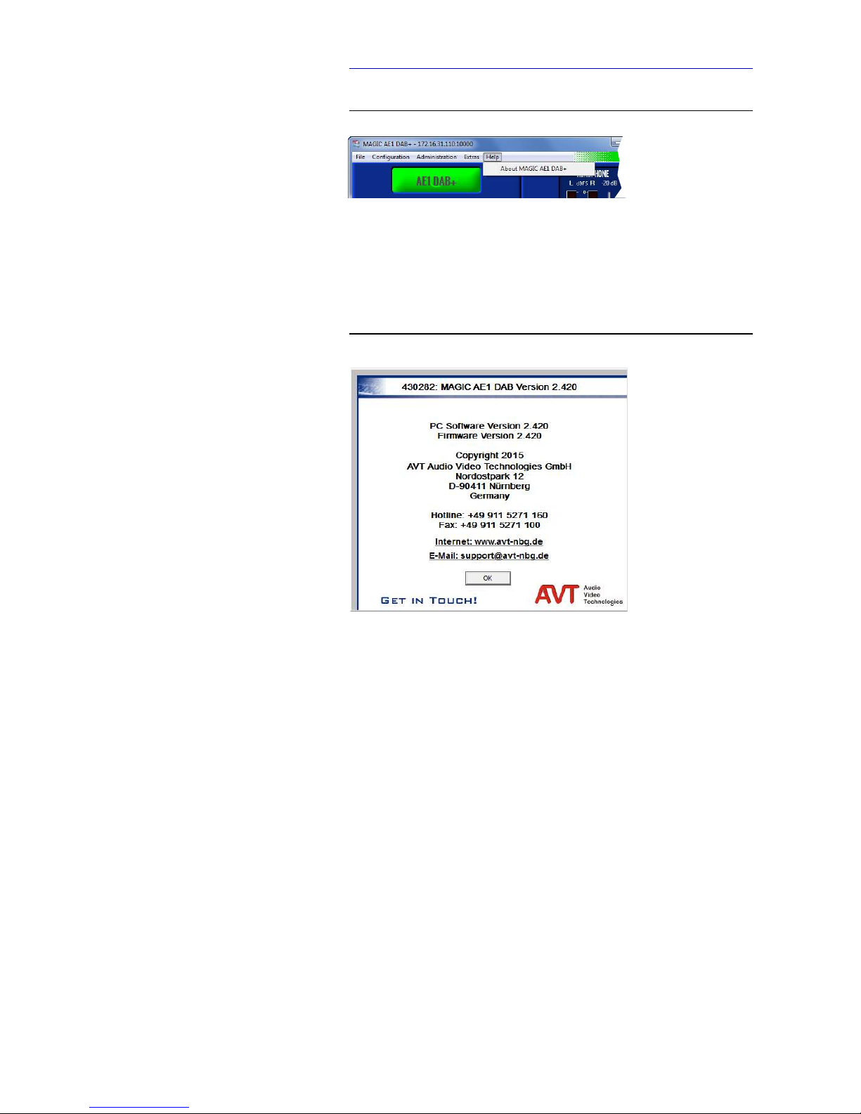
PAG E 8 4
W i n d o w s P C S o f t w a r e
5.8 Menu Help
FIG. 54 MENU HELP
5.8.1 Submenu About MAGIC AE1 DAB+
In the About MAGIC AE1 DAB+ dialogue you find the software versions of
the PC software (PC Version) and of the system (Firmware Version). Besides, you can find our contact details there.
FIG. 55 SUBMENU ABOUT MAGIC AE1 DAB+
Page 85

PAG E 8 5
M e n u S t r u c t u r e
A 1 M E N U S T R U C T U R E
On the following pages you will find the complete menu structure if you select as menu language
With the use of the softkey you get to the configuration of the system.
The configuration menu is divided in five submenus:
–
–
–
–
–
If you use an Administrator and/or User Password, the display looks as it is
described below:
(1) Only Administrator Password configured: The password must be en-
tered for changes to the basic settings and operation settings only. Immediately available menus:
–
–
–
(2) Only User Password configured (instead of is displayed):
The password must always be entered. Subsequently, all menus are
available.
(3) User and Administrator Password configured (instead of is
displayed):
– User Password is entered: The menus ,
and are available
– Administrator Password is entered: All menus are available.
NOTE
Please note that depending on the selected operating mode some menu items
are not displayed.
NOTE
There is no differentiation between upper and lower case for the password
entry.
Page 86
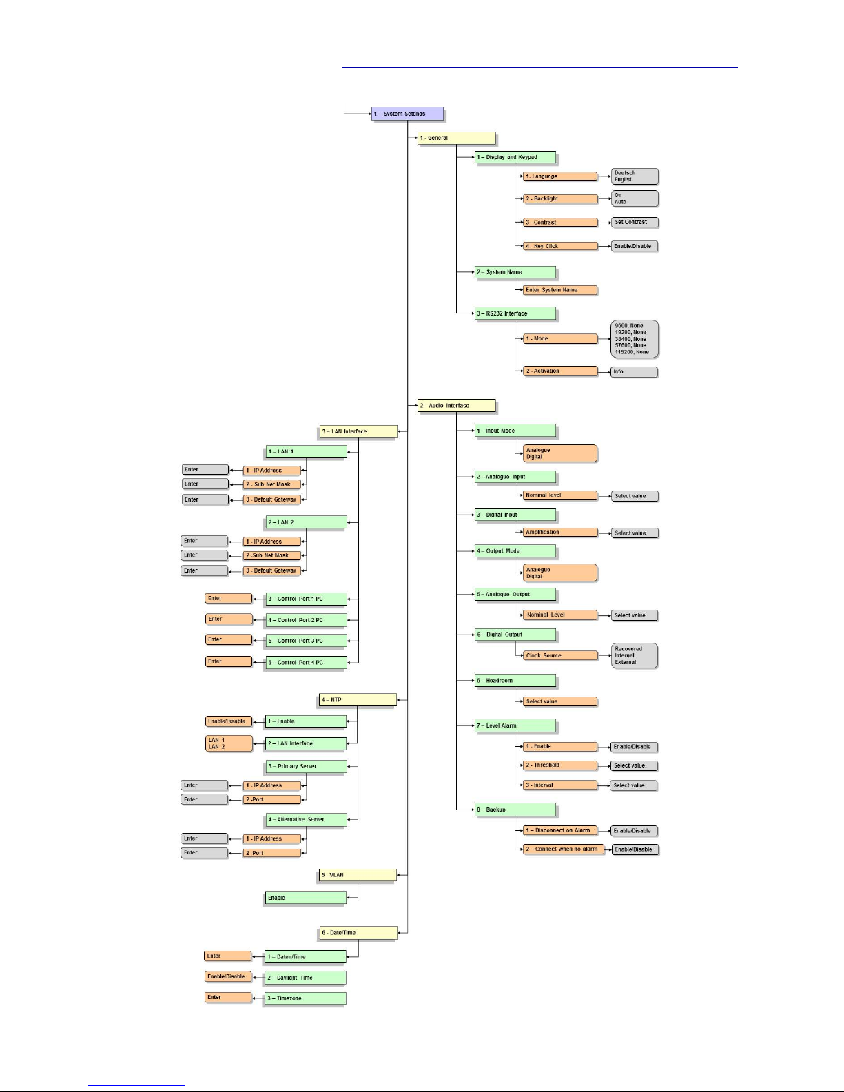
PAG E 8 6
M e n u S t r u c t u r e
A1.1 System Settings
Page 87
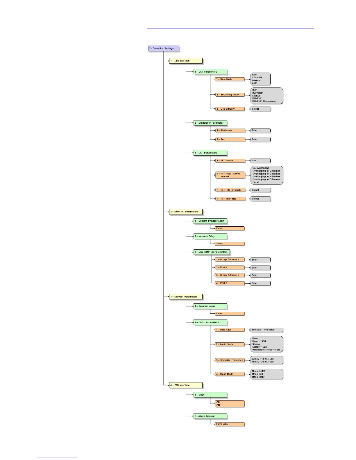
PAG E 8 7
M e n u S t r u c t u r e
A1.2 Operation Settings
Page 88
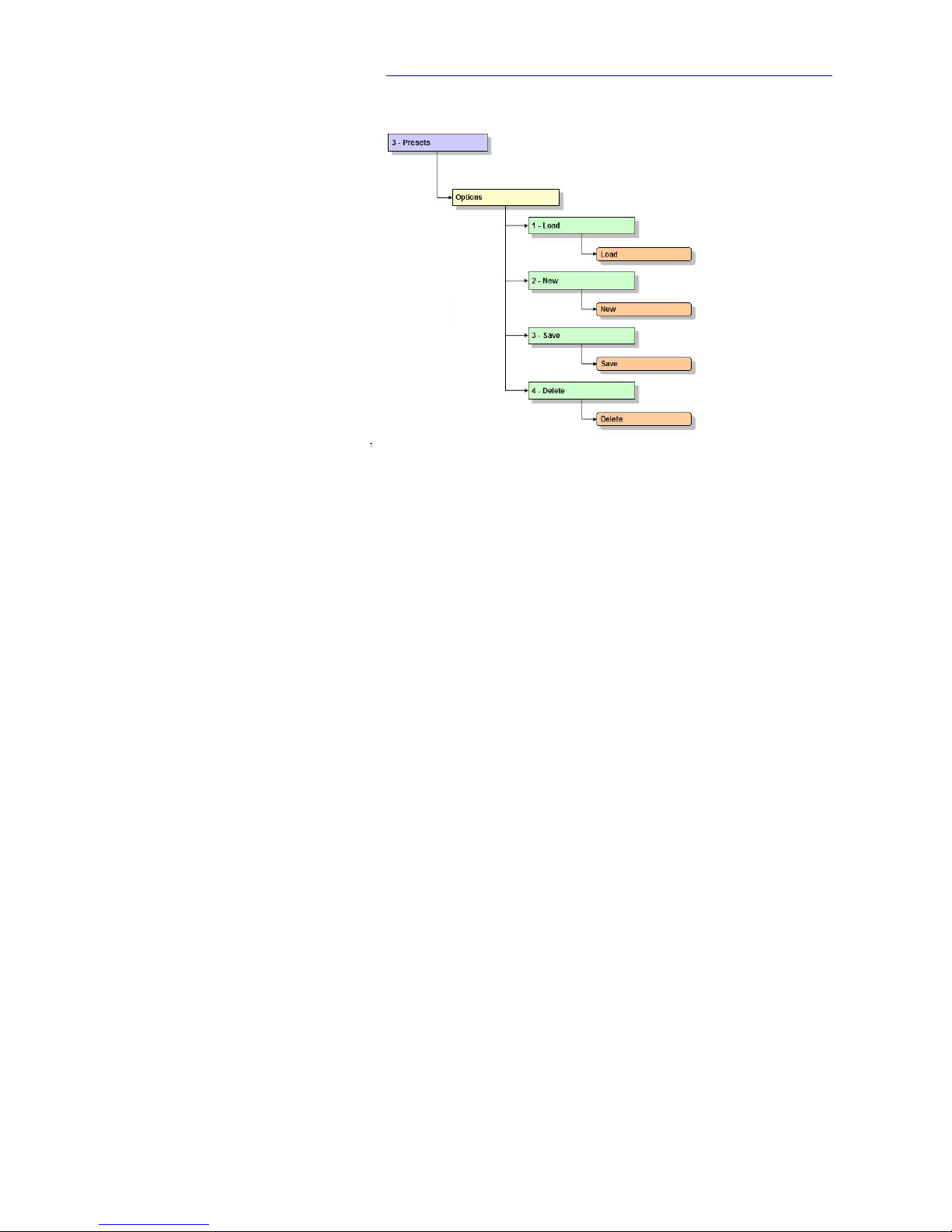
PAG E 8 8
M e n u S t r u c t u r e
A1.3 Presets
Page 89
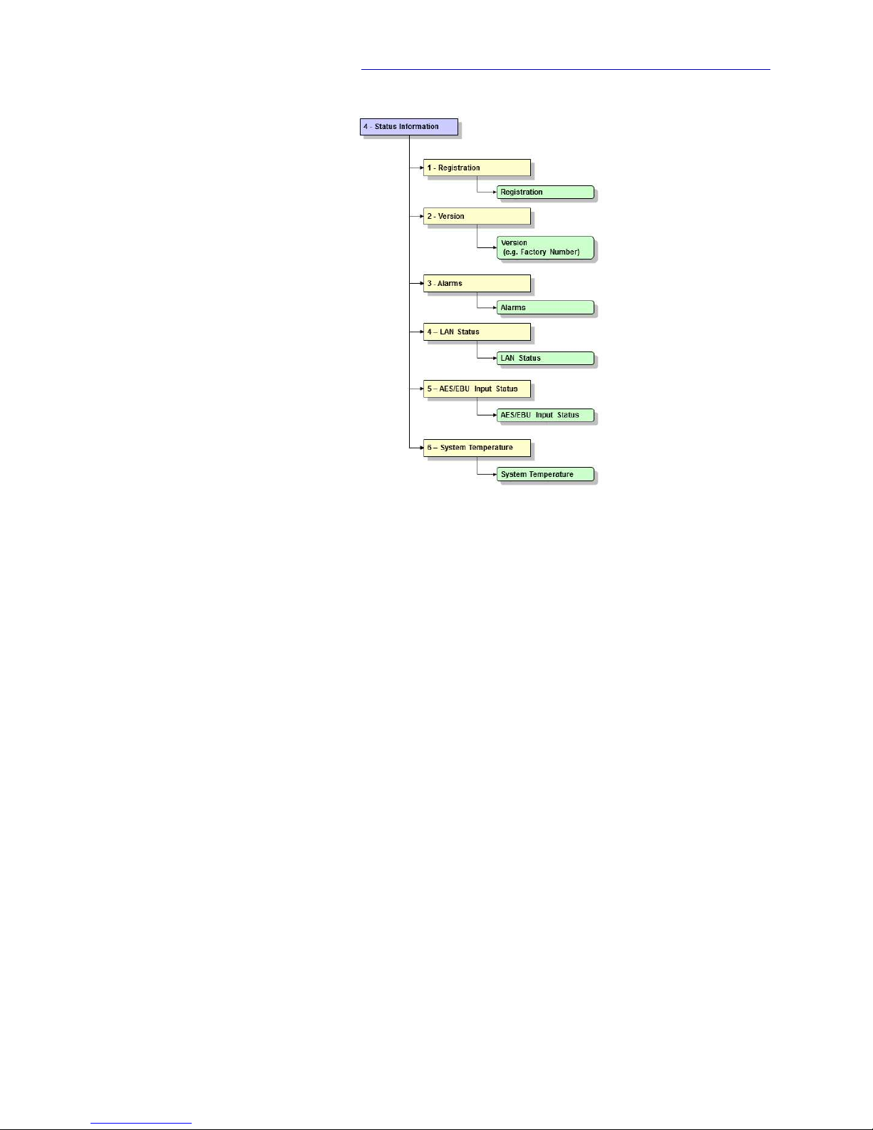
PAG E 8 9
M e n u S t r u c t u r e
A1.4 Status Information
Page 90

PAG E 9 0
M e n u S t r u c t u r e
A1.5 Login
Page 91
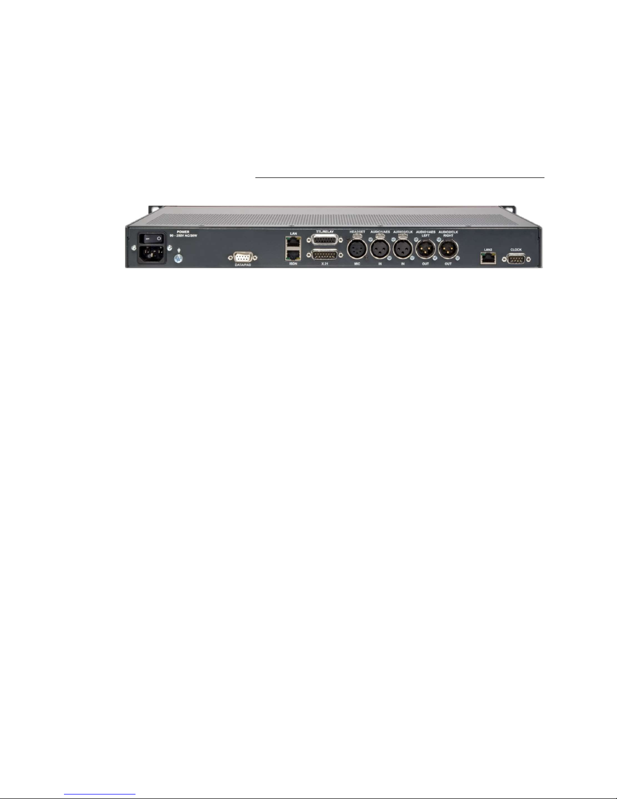
PAG E 9 1
I n t e r f a c e s
A 2 I N T E R F A C E S
The interfaces of the system are pictured in Fig. 56.
FIG. 56 REAR VIEW OF THE MAGIC AE1 DAB+ AUDIO ENCODER
All interfaces are described below.
Page 92

PAG E 9 2
I n t e r f a c e s
A2.1 Control and data interfaces
A2.1.1 DATA/PAD interface
The DATA/PAD interface can be used for the transmission of Program Associated Data (PAD). The interface is realised compliant to IRT Recommenda-
tion1.
To connect a standard PAD inserter you need a 1:1 connecting cable in which
Pin 2 and Pin 3 are not crossed. Furthermore, Pin 5 GND must be connected.
ATTENTION For maximum bit rates of the PDA channel please refer to TAB. 2, Maximum
bitrate of F-PAD and X-PAD data.
1
Synchronous transmission mode: In the beginning of each ISO/MPEG frame the encoder transmit a SYN character (0x16). To realise frame synchronous PAD insertion the connected PAD inserter must transmit all data inside of this frame.
NOTE
Please note that the function of the Pins RXD and TXD - input or output - is
determined by the interface type DCE or DTE. The pin assignment for Pin 2
is always RXD and for Pin 3 it is always TXD.
TAB. 3 PIN ASSIGNMENT: DATA/PAD INTERFACE
Socket: SUB-D, 9-pole
Pin
Signal Electrical characteristics
1
not used PC interface RS232:
Type (Pin 2, 3): DCE
a
Level: V.24
Data rate: 115200 Baud
Range: max. 15 m
Protocol: programmable
a DCE = Data Communication Equipment: to connect a PC a 1:1 cable is required
2
RXD
b
PAD Receive Data
b ATTENTION: On this Pin the MAGIC AE1 DAB+ transmits data
3
TXD
c
PAD Transmit Data
c ATTENTION: On this Pin the MAGIC AE1 DAB+ receives data
4
not used
5
GND Earth
6
not used
7
not used
8
not used
9
not used
!
5
1
9
6
Page 93
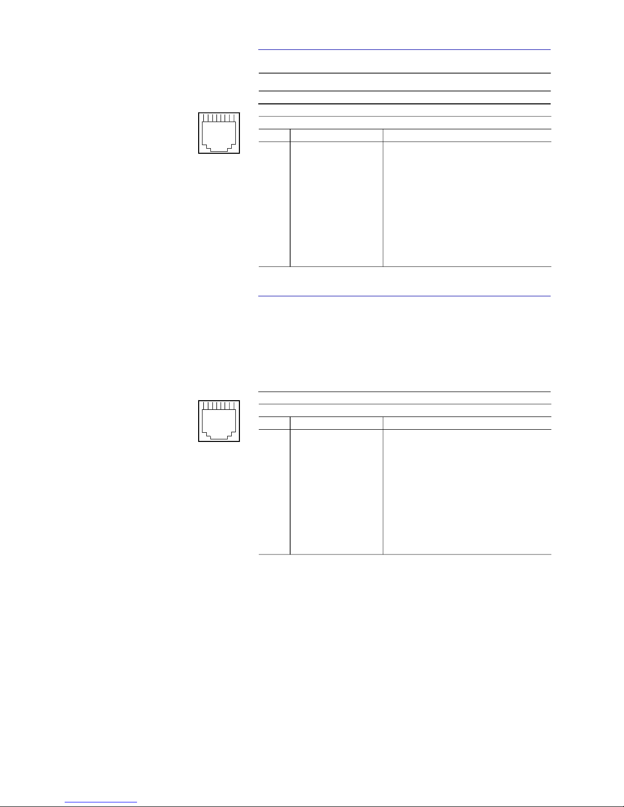
PAG E 9 3
I n t e r f a c e s
A2.2 ISDN interface
A2.3 LAN interfaces
The system provides one LAN interface in the standard delivery. Optionally,
it can be extended with a second LAN interface which can be integrated or implemented as external LAN2 adapter. The standard LAN interface can be
used for audio transmission, control and monitoring purposes. The LAN2 interface can be used for control, PAD or SNMP.
NOTE
This interface is not supported in the MAGIC AE1 DAB+ system.
TAB. 4 PIN ASSIGNMENT: S0 INTERFACE (ISDN)
Socket: Western (8-pole) RJ45
Pin
Signal Electrical characteristics
1
not used Recommendation: I.430
Data rate: B channel: 2 x 64-kbit/s
D channel: 16-kbit/s
Max. cable length: 100 m
2
not used
3
TX (A) Data out (A)
4
RX (A) Data in (A)
5
RX (B) Data in (B)
6
TX (B) Data out (B)
7
not used
8
not used
TAB. 5 PIN ASSIGNMENT: LAN INTERFACE
Socket: Western (8-pole) RJ45
Pin
Signal Electrical characteristics
1
TX (A) Data out (A) Standard Ethernet /10Base-T (IEEE-802.3)
Speed: 10 MBit/s
Cable type: Twisted Pair (CAT3)
Max. cable length: 100 m
Fast Ethernet /100Base-T (IEEE-802.3u)
Speed: 100 MBit/s
Cable type: Twisted Pair (min. CAT5)
Max. cable length: 100 m
2
TX (B) Data out (B)
3
RX (A) Data in (A)
4
not used
5
not used
6
RX (B) Data in (B)
7
not used
8
not used
1
8
1
8
Page 94

PAG E 9 4
I n t e r f a c e s
A2.4 X.21 interface
The X.21 interface is realised as DTE (Data Terminal Equipment) interface.
The MAGIC AE1 DAB+ can be connected via an X.21 cable directly to any Ensemble Multiplexer which supports the STI-D standard on the X.21 interface
(e.g. R&S DM-001).
FIG. 57 PIN ASSIGNMENT: X.21 INTERFACE
Connector: 15-pole SUB-D
Pin
Signal
Direction
Electrical characteristics
1
SHIELD Screen Type: DTE
Level: V.11, balanced
Data rates: n x 8 kbit/s
n = 1 ... 24
Range: 100 m
2
TX (A) Transmit Data (A)
Out
3
CTL (A) Control (A)
Out
4
RX (A) Receive Data (A)
In
5
IND (A) Indicate (A)
In
6
SCLK (A) Signal Element Timing (A)
In
7
BCLK (A)aByte Timing (A)
a Normally not used
In
8
GND Ground
9
TX (B) Transmit Data (B)
Out
10
CTL (B) Control (B)
Out
11
RX (B) Receive Data (B)
In
12
IND (B) Indicate (B)
In
13
SCLK (B) Signal Element Timing (B)
In
14
BCLK (B)aByte Timing (B)
In
15
not used
NOTE
The MAGIC AE1 DAB+ Audio Encoder Firmware and PC Software supports
the X.21 operating mode until software version 2.320. With later software releases only the LAN operating mode is possible.
81
159
Page 95

PAG E 9 5
I n t e r f a c e s
A2.5 TTL/RELAY interface
Via this interface external control signals can be used. The programming of
the available functions is possible via the Windows PC Software.
TAB. 6 PIN ASSIGNMENT: TTL/RELAY INTERFACE
Socket: 15-pole SUB-D
Pin
Signal
Direction
Electrical characteristics
1
not used Specification of the TTL outputs:
Maximum voltage: 5V
Maximum current: 10mA
Specification of the relays:
Maximum voltage: 48V
Maximum current: 200mA
2
not used
3
not used
4
not used
5
GND
6
RELAY 1 (A)
Out
7
RELAY 1 (B)
Out
8
RELAY 2 (A)
Out
9
TTL1
In/Out
10
TTL2
In/Out
11
TTL3
In/Out
12
TTL4
In/Out
13
TTL5
In/Out
14
TTL6
In/Out
15
RELAY 2 (B)
Out
18
915
Page 96
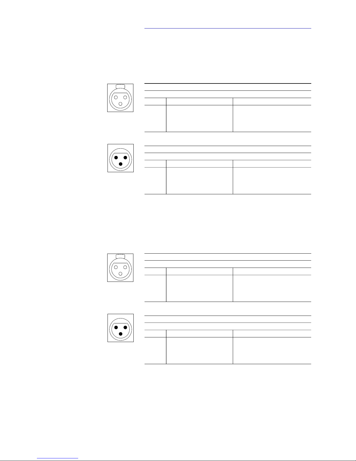
PAG E 9 6
I n t e r f a c e s
A2.6 Audio interfaces
The system incorporates analogue and digital AES/EBU audio interfaces. For
switching you can use display and keypad or the Windows PC software. The
output interfaces can be used for monitoring purposes.
A2.6.1 Analogue Audio interface
A2.6.2 Digital AES/EBU Audio interface
The MAGIC AE1 DAB+ system incorporates a digital AES/EBU input and output. The input as well as the output has its own sample rate converter providing that a digital source with 32, 44.1 or 48-kHz can be connected directly. For
external clocking (48-kHz only) the word clock input or output may be used.
TAB. 7 PIN ASSIGNMENT: ANALOGUE INPUT (AUDIO 1/2 IN)
Socket: 3-pole XLR
Pin
Signal Electrical characteristics
1
GND Input level: adjustable -3 .... +9 dBu
Impedance: > 25 k
Headroom: 6 dB
2
AUDIO IN (A)
3
AUDIO IN (B)
TAB. 8 PIN ASSIGNMENT: ANALOGUE OUTPUT (AUDIO 1/2 OUT)
Connector: 3-pole XLR
Pin
Signal Electrical characteristics
1
GND Output level: adjustable -3 .... +9 dBu
Impedance: < 50
Headroom: 6 dB
2
AUDIO OUT (A)
3
AUDIO OUT (B)
TAB. 9 PIN ASSIGNMENT: DIGITAL INPUT (AES IN)
Socket: 3-pole XLR
Pin
Signal Electrical characteristics
1
GND IEC-958
2
AUDIO IN (A)
3
AUDIO IN (B)
TAB. 10 PIN ASSIGNMENT: DIGITAL OUTPUT (AES OUT)
Connector: 3-pole XLR
Pin
Signal Electrical characteristics
1
GND IEC-958
2
AUDIO OUT (A)
3
AUDIO OUT (B)
Push
12
3
2
1
3
Push
12
3
2
1
3
Page 97
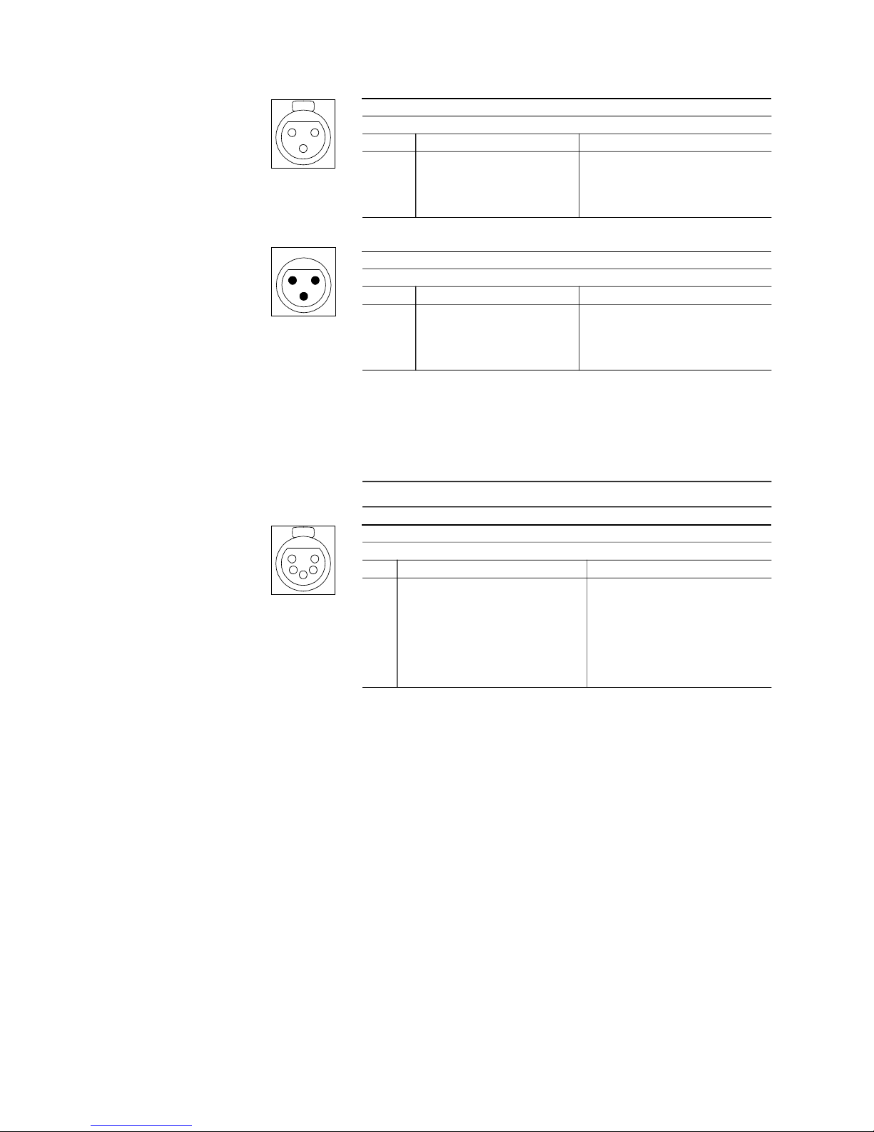
PAG E 9 7
I n t e r f a c e s
A2.6.2.1 Digital AES/EBU Clock interface
A2.6.3 HEADSET/MIC interface
This interface allows a monitoring of the decoded audio signal as well as the
audio inputs.
TAB. 11 PIN ASSIGNMENT: CLOCK INPUT (CLK IN)
Socket: 3-pole XLR
Pin
Signal Electrical characteristics
1
GND TTL
2
CLOCK IN
3
not used
TAB. 12 PIN ASSIGNMENT: CLOCK OUTPUT (CLK OUT)
Connector: 3-pole XLR
Pin
Signal Electrical characteristics
1
GND TTL
2
CLOCK OUT
3
not used
NOTE
The microphone input is not available in this system.
TAB. 13 PIN ASSIGNMENT: HEADSET/MICRO AUDIO INTERFACE
Socket: 5-pole XLR
Pin
Signal Electrical characteristics
1
not used Output Power: 0,15 W
Load (Min.): 8
THD+N@1kHz: 0,25% (half power)
PSRRa: 83 dB
Level adjustment: 0 ... -40 dB
a PSRR: Power Supply Rejection Ratio
2
not used
3
GND
4
HEADPHONE left channel
5
HEADPHONE right channel
Push
12
3
2
1
3
Push
15
3
24
Page 98

PAG E 9 8
I n t e r f a c e s
Page 99

PAG E 9 9
T e c h n i c a l D a t a
A 3 T E C H N I C A L D A T A
Coding Algorithm
HE-AAC-V2 (FhG Licence)
ETSI TS 102 563
Sampling Frequencies:
16-kHz, 32-kHz, 24-kHz, 48-kHz
Data Rates:
n x 8-kbit/s n=1...24
Audio Interface Encoder:
XLR, analogue, electronically balanced
digital AES/EBU with integrated Sample Rate Converter
Audio Level:
-3 ... +9 dBu
Headroom:
adjustable
Impedance:
15 KOhm
THD+N:
~86 dB
Linearity:
± 0,3 dB
Page 100

PAG E 1 00
Monitoring Output:
XLR, analogue, electronically balanced
digital AES/EBU with integrated Sample Rate Converter
Headphones output
Line Interfaces:
X.21 (STI-D protocol)
LAN (UDP, IP Unicast, IP Multicast,
IP Simulcast (three streams))
Data Interfaces:
PAD V.24/RS232 IRT Rec. compliant
38400, 57600, 115200 Baud
max. bit rate, see TAB. 2, Page 47
Control Interface:
LAN
PC V.24/RS232
GPIO 6 x TTL programmable
2 x Relays, programmable
Power Supply:
90...253V AC
Frequency:
50/60 Hz
Power Consumption:
typical 12W, max. 15W
Dimensions (H x W x D):
45 (1U) x 451 x 250 mm
with brackets system fits into a 19“ rack
 Loading...