

Page 1
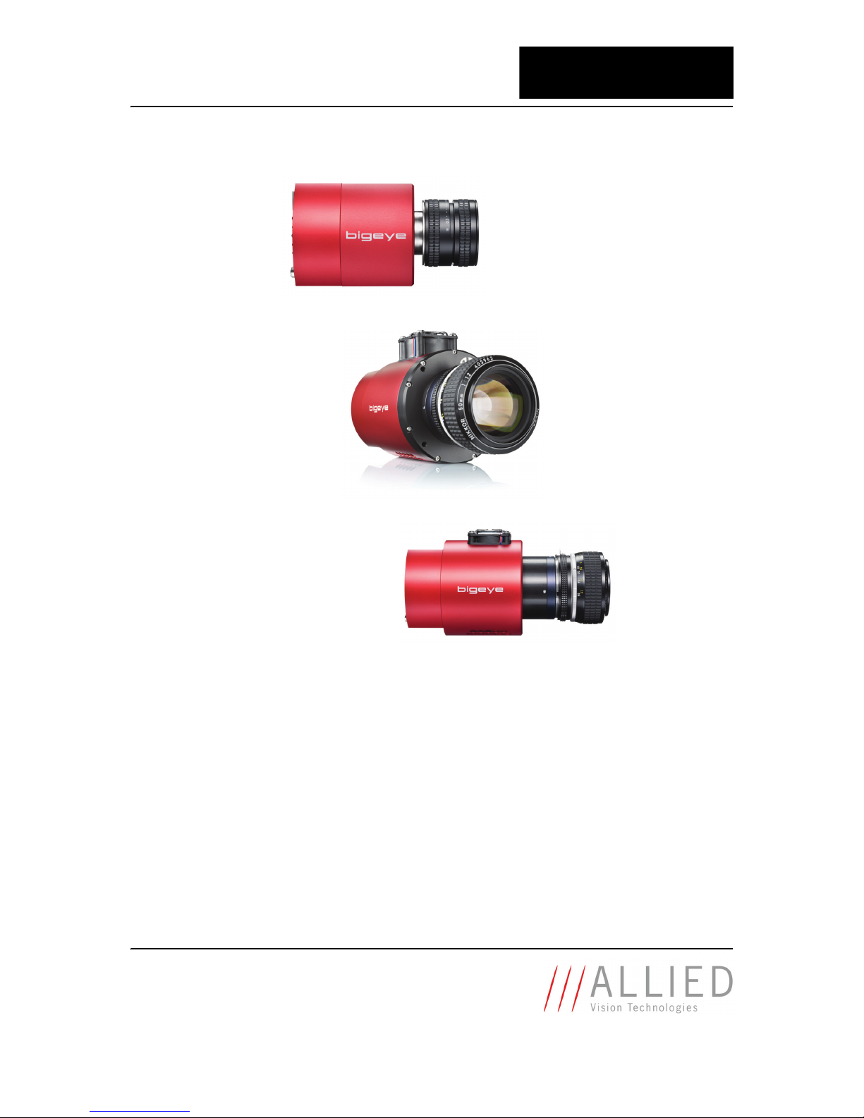
Technical Manual
Low-noise or cooled CCD camera with GigE interface
V2.0.0
03 November 2011
Allied Vision Technologies GmbH
Taschenweg 2a
D-07646 Stadtroda / Germany
AVT Bigeye
Page 2

Bigeye Technical Manual V2.0.0
2
Legal notice
Life support applications
These products are not designed for use in life support appliances, devices, or systems where malfunction of these products can reasonably be expected to result in personal injury. Allied Vision
Technologies customers using or selling these products for use in such applications do so at their
own risk and agree to fully indemnify Allied for any damages resulting from such improper use or
sale.
Trademarks
Unless stated otherwise, all trademarks appearing in this document of Allied Vision Technologies
are brands protected by law.
Warranty
The information provided by Allied Vision Technologies is supplied without any guarantees or
warranty whatsoever, be it specific or implicit. Also excluded are all implicit warranties concerning the negotiability, the suitability for specific applications or the non-breaking of laws and patents. Even if we assume that the information supplied to us is accurate, errors and inaccuracy may
still occur.
Copyright
All texts, pictures and graphics are protected by copyright and other laws protecting intellectual
property. It is not permitted to copy or modify them for trade use or transfer, nor may they be used
on web sites.
Allied Vision Technologies GmbH 11/2011
All rights reserved.
Managing Director: Mr. Frank Grube
Tax ID: DE 184383113
Headquarters:
Taschenweg 2A
D-07646 Stadtroda, Germany
Tel.: +49 (0)36428 6770
Fax: +49 (0)36428 677-28
e-mail: [email protected]
Page 3

Bigeye Technical Manual V2.0.0
3
Contents
Contacting Allied Vision Technologies ................................................... 5
Introduction ............................................................................................................ 6
Document history............................................................................................................ 6
Manual overview ............................................................................................................. 6
Conventions used in this manual ........................................................................................ 7
Styles ....................................................................................................................... 7
Symbols.................................................................................................................... 7
Before operation............................................................................................................. 8
Safety warnings .............................................................................................................. 8
Conformity ............................................................................................................... 9
CE............................................................................................................................ 9
Specifications .......................................................................................................10
Bigeye P-132B.............................................................................................................. 10
Bigeye P-132B/C Cool / Bigeye P-132B Solar Cool................................................................ 12
Bigeye P-629B Cool / P-629B Solar Cool ............................................................................ 14
Bigeye P-1100B/C Cool................................................................................................... 16
Spectral sensitivity ........................................................................................................ 18
Camera dimensions ..........................................................................................21
Bigeye P-132B.............................................................................................................. 21
Bigeye P-132B/C Cool and P-132B Solar Cool...................................................................... 23
Bigeye P-629B Cool / Solar Cool....................................................................................... 25
Bigeye P-1100B/C Cool................................................................................................... 27
Camera interfaces .............................................................................................29
Control junction............................................................................................................ 29
Camera I/O connector pin assignment (15-pin D-Sub jack)................................................ 29
Power supply (Pin 1-4)............................................................................................... 31
Mode input (Pin 9) .................................................................................................... 32
Trigger input (Pin 10, 11) ........................................................................................... 33
Exposure output (Pin 12, 13)....................................................................................... 34
Line-sync output (Pin 14) ........................................................................................... 35
Frame-sync output (Pin 15)......................................................................................... 36
GigE interface............................................................................................................... 37
Pin assignment of Gigabit Ethernet jack......................................................................... 37
Exposure control ...................................................................................................... 38
Mode setting............................................................................................................ 39
Binning .................................................................................................................. 40
Gain ....................................................................................................................... 41
Page 4

Bigeye Technical Manual V2.0.0
4
Appendix..................................................................................................................42
GigE Vision feature description for AVT Bigeye cameras ......................................................... 42
DeviceInformation .................................................................................................... 42
ImageSizeControl ..................................................................................................... 43
AcquisitionControl .................................................................................................... 44
AnalogControls ........................................................................................................ 44
CameraSpecialFeatures .............................................................................................. 45
Index...........................................................................................................................46
Page 5

Contacting Allied Vision Technologies
Bigeye Technical Manual V2.0.0
5
Contacting Allied Vision Technologies
Info
• Technical information:
http://www.alliedvisiontec.com
• Support:
Allied Vision Technologies GmbH (Headquarters)
Taschenweg 2a
07646 Stadtroda, Germany
Tel.: +49 36428-677-0
Fax.: +49 36428-677-28
e-mail: [email protected]
Allied Vision Technologies Canada Inc.
101-3750 North Fraser Way
Burnaby, BC, V5J 5E9, Canada
Tel: +1 604-875-8855
Fax: +1 604-875-8856
e-mail: [email protected]
Allied Vision Technologies Inc.
38 Washington Street
Newburyport, MA 01950, USA
Tel.: +1 978-225-2030
Fax: +1 978-225-2029
e-mail: [email protected]
Allied Vision Technologies Asia Pte. Ltd.
82 Playfair Road
#07-02 D’Lithium
Singapore 368001
Tel: +65 6634-9027
Fax: +65 6634-902
e-mail: [email protected]
Page 6

Introduction
Bigeye Technical Manual V2.0.0
6
Introduction
This Bigeye Technical Manual describes in depth the technical specifications,
dimensions, all pixel formats, bandwidth and frame rate related subjects.
Document history
Manual overview
This manual overview outlines the contents of each chapter of this manual.
•Chapter Contacting Allied Vision Technologies on page 5 lists AVT contact
data (phone numbers and URLs) for both:
– Technical information / ordering
– Commercial information
•Chapter Introduction on page 6 (this chapter) gives you the document his-
tory, a manual overview (short description of each chapter) and conventions used in this manual (styles and symbols).
•Chapter Conformity on page 9 gives you information about conformity of
AVT cameras (CE, RoHS).
•Chapter Specifications on page 10 lists camera details and measured spec-
tral sensitivity diagrams for each camera type.
•Chapter Camera dimensions on page 21 provides CAD drawings of stan-
dard housing models, tripod adapter.
•Chapter Camera interfaces on page 29 describes in general the inputs/
outputs of the cameras (incl. trigger features).
Note
Please read through this manual carefully.
We assume that you have read already the How to install a GigE
camera (Bigeye/Pearleye/Goldeye) and that you have
installed the hardware and software on your PC or laptop (GigE
interface card, cables etc.).
http://www.alliedvisiontec.com/emea/support/downloads/
product-literature.html
Version Date Description
V2.0.0 03.11.11 New Bigeye Technical Manual
Table 1: Document history
Page 7
Introduction
Bigeye Technical Manual V2.0.0
7
•Chapter Index on page 46 gives you quick access to all relevant data in
this manual.
Conventions used in this manual
To give this manual an easily understood layout and to emphasize important
information, the following typographical styles and symbols are used:
Styles
Symbols
Style Function Example
Bold Programs, inputs or highlighting
important things
bold
Courier Code listings etc. Input
Upper case Register REGISTER
Italics Modes, fields Mode
Parentheses and/or blue Links (Link)
Table 2: Styles
Note
This symbol highlights important information.
Caution
This symbol highlights important instructions. You have to
follow these instructions to avoid malfunctions.
www
This symbol highlights URLs for further information. The URL
itself is shown in blue.
Example:
http://www.alliedvisiontec.com
Page 8

Introduction
Bigeye Technical Manual V2.0.0
8
Before operation
We place the highest demands for quality on our cameras.
Target group This Technical Manual is the guide to detailed technical information of the
camera and is written for experts.
Safety warnings
Note
Please read through this manual carefully before operating
the camera.
Caution
Before operating any AVT camera read the following safety
instructions and ESD warnings.
Caution
Electrostatic discharge
The camera contains sensitive electronic components which
can be destroyed by means of electrostatic discharge.
Use sufficient grounding to minimize the risk of damage.
Page 9

Conformity
Bigeye Technical Manual V2.0.0
9
Conformity
Allied Vision Technologies declares under its sole responsibility that all standard cameras of the Bigeye family to which this declaration relates are in conformity with the following standard(s) or other normative document(s):
• CE, following the provisions of 2004/108/EG directive
• RoHS (2002/95/EC)
CE
We declare, under our sole responsibility, that the previously described Bigeye
cameras conform to the directives of the CE.
Page 10
Specifications
Bigeye Technical Manual V2.0.0
10
Specifications
Bigeye P-132B
Note
The warranty becomes void in case of unauthorized tampering
or any manipulations not approved by the manufacturer.
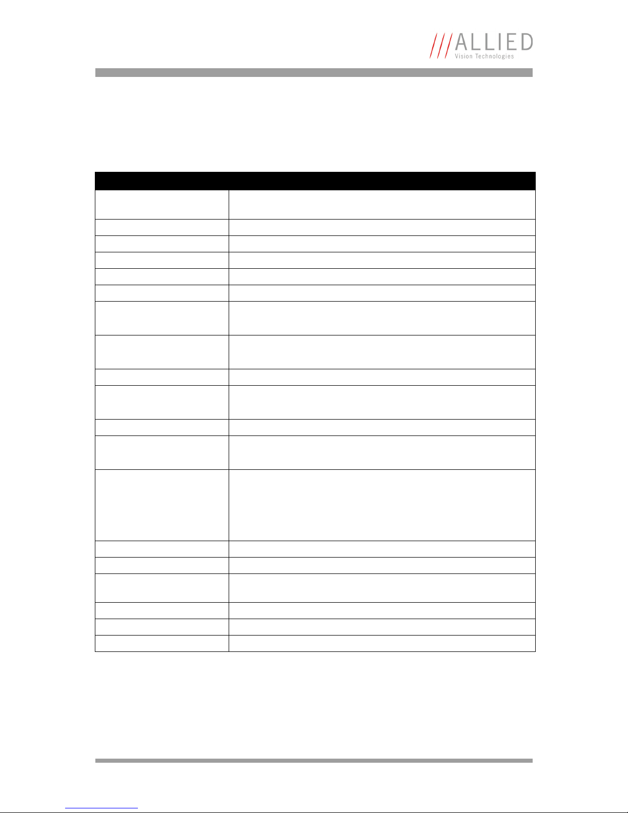
Feature Specification
Image device Type 2/3, progressive scan, Sony ICX 285AL, interline transfer sensor (no
mechanical shutter required) EXView HAD
Effective chip size 8.62 mm (H) x 6.6 mm (V)
Cell size 6.45 μm x 6.45 μm
Picture size (max.) 1280 (H) x 1024 (V)
Lens mount C-Mount
Pixel format Mono8, Mono10, Mono12
Frame rate up to 12.5 fps (full frame)
up to 25 fps (binning: 1280 x 512)
ADC 14 bits
Exposure time 0.1 ms ... 1000 seconds in 76 μs steps
Digital output 12-bit, GigE
I/Os Two inputs (one optocoupled)
three outputs (one optocoupled)
Smart features Vertical binning (1 x 2), switchable gain (+ 6 dB), continuous mode
(image acquisition with maximum frame rate), image-on-demand mode
(triggered image acquisition)
With AVT AcquireControl: BCG LUT, auto contrast, auto brightness, analyze multiple regions within image, real-time statistics and histogram
Digital interface IEEE 802.3 1000BASE-T (GigE Vision V1.2)
Power requirements + 12 V (+5 %), max. 0.8 A
Dimensions 89 mm x 90 mm x 71 mm (L x W x H);
incl. connectors, without tripod and lens
Mass 790 g (without lens)
Table 3: Specification Bigeye P-132B
Page 11
Specifications
Bigeye Technical Manual V2.0.0
11
Environmental air temperature 0 °C ... 35 °C
Regulations CE, RoHS (2002/95/EC)
Note
The design and specifications for the products described above
may change without notice.
Note
• The right polarization of the 12 V supply voltage has to
be taken into consideration.
• The warranty becomes void in case of unauthorized tampering or any manipulations not approved by the manufacturer.
Feature Specification
Table 3: Specification Bigeye P-132B
Page 12
Specifications
Bigeye Technical Manual V2.0.0
12
Bigeye P-132B/C Cool / Bigeye P-132B Solar
Cool
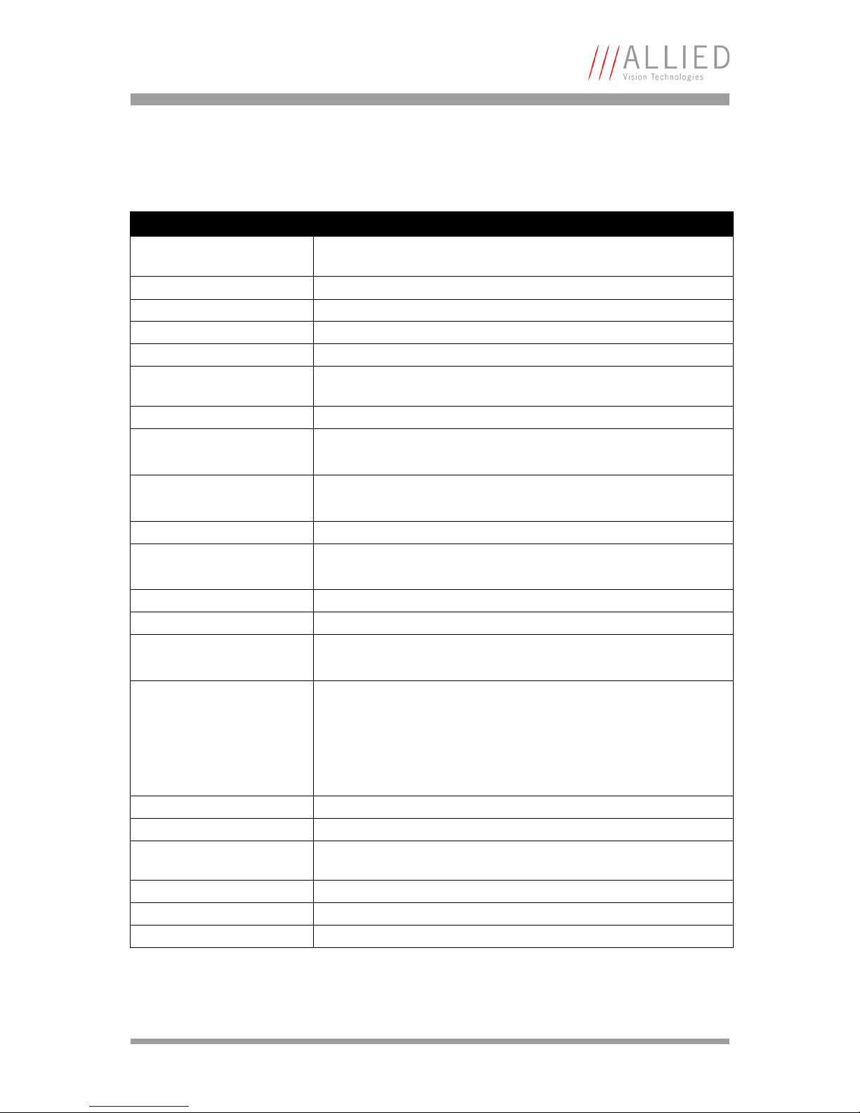
Feature Specification
Image device Type 2/3, progressive scan, Sony ICX 285AL, interline transfer sensor (no
mechanical shutter required) ExView HAD
Effective chip size 8.62 mm (H) x 6.6 mm (V)
Cell size 6.45 μm x 6.45 μm
Picture size (max.) 1280 (H) x 1024 (V)
Lens mount C-Mount
ADC 14 bits
Pixel format Mono8, Mono10, Mono12
Bigeye P-132C Cool: additional BayerGB8, BayerGB10, BayerGB12
Frame rate up to 12.5 fps (full frame)
up to 25 fps (binning Cool: 1280 x512, binning Solar: 640 x 512)
Exposure time 100 μs ... 1000 seconds in adjustable in 76 μs steps
Cooling Peltier cooling
- 20 °C regulated (up to 25 °C ambient temperature)
Digital output 12-bit, GigE
I/Os Two inputs (one optocoupled)
three outputs (one optocoupled)
Smart features Binning (Cool: 1 x 2; Solar: 2 x2) , Gain (+ 6 dB), continuous mode
(image acquisition with maximum frame rate), image-on-demand mode
(triggered image acquisition)
With AVT AcquireControl: BCG LUT, auto contrast, auto brightness, analyze multiple regions within image, real-time statistics and histogram
Digital interface IEEE 802.3 1000BASE-T (GigE Vision V1.2)
Power requirements + 12 V (+ 5 %), max. 2.8 A
Dimensions 111 mm x 90 mm x 99 mm (L x W x H);
incl. connectors, without tripod and lens
Mass 1410 g (without lens)
Operating temperature 0 °C ... 35 °C
Regulations CE, RoHS (2002/95/EC)
Table 4: Specification Bigeye P-132B/C Cool, Bigeye P-132B Solar Cool
Page 13

Specifications
Bigeye Technical Manual V2.0.0
13
Note
The design and specifications for the products described above
may change without notice.
Note
• The right polarizat ion of the 12 V supply voltage has to
be taken into consideration.
• The two hexagon socket screws (M 5) in the front plate
may in no case be loosened as otherwise the vacuum area
is getting leaky.
• The warranty becomes void in case of unauthorized tampering or any manipulations not approved by the manufacturer.
Page 14
Specifications
Bigeye Technical Manual V2.0.0
14
Bigeye P-629B Cool / P-629B Solar Cool
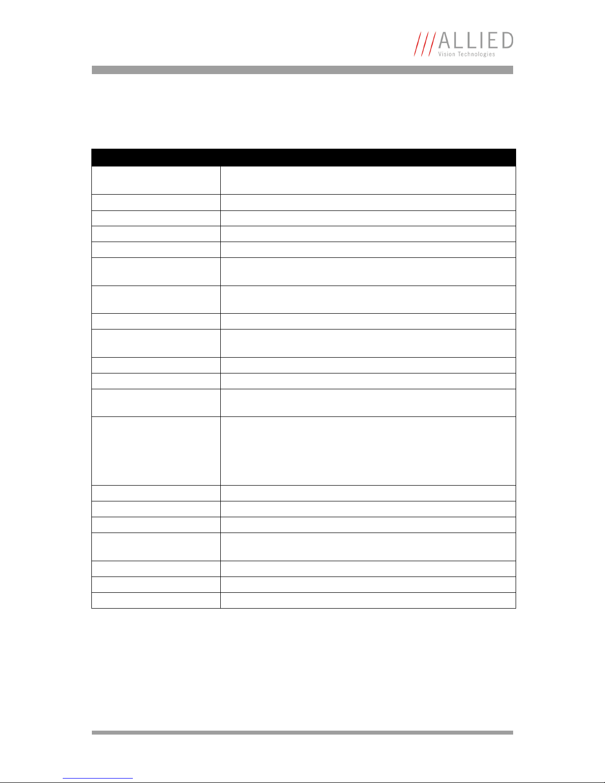
Feature Specification
Image device Type 35 mm, CCD progressive scan, Kodak KAF-6303E, full-frame transfer
sensor
Effective chip size 27.65 mm (H) x 18.48 mm (V)
Cell size 9.00 μm x 9.00 μm
Picture size (max.) 3072 (H) x 2048 (V)
Lens mount F-Mount
Shutter 50 ms ... 30 min.
(built-in electromechanical long-live shutter: min. 1 x 10
6
cycles)
Pixel format Mono8, Mono10, Mono12, Mono14, Mono16
Frame rate up to 0.5 fps (full frame)
up to 1 fps (binning: 1536 x 1024)
Readout time 1.35 s at 3072 x 2048
0.4 s at 1536 x 1024
Exposure time 50 ms ... 30 min.
Cooling Peltier cooling
+5 °C stabilized
ADC 14 bits
Digital output 14-bit, GigE
I/Os Two inputs (one optocoupled)
three outputs (one optocoupled)
Smart features Binning (2 x 2), switchable gain (+ 6 dB),
continuous mode (image acquisition with maximum frame rate),
image-on-demand mode (triggered image acquisition)
With AVT AcquireControl: BCG LUT, auto contrast, auto brightness,
analyze multiple regions within image, real-time statistics and
histogram
Digital interface IEEE 802.3 1000BASE-T (GigE Vision V1.2)
Power requirements + 12 V (+ 5 %), approx. 1.3 A ... 2.8 A
Dimensions 141.75 mm x 90 mm x 109 mm (L x W x H); incl. connectors, without
tripod and lens
Mass 1480 g (without lens)
Operating temperature 0 °C ... 35 °C
Regulations CE, RoHS (2002/95/EC)
Table 5: Specification Bigeye P-629B Cool / P-629B Solar Cool
Page 15

Specifications
Bigeye Technical Manual V2.0.0
15
Note
The design and specifications for the products described above
may change without notice.
Note
• The right polarization of the 12 V supply voltage has to
be taken into consideration.
• The warranty becomes void in case of unauthorized tampering or any modifications not approved by the manufacturer.
Page 16
Specifications
Bigeye Technical Manual V2.0.0
16
Bigeye P-1100B/C Cool
Feature Specification
Image device Type 35 mm, CCD progressive scan, Kodak KAI11002, interline transfer
sensor (IT) (no mechanical shutter required) global shutter
Effective chip size 36.18 mm (H) x 24.12 mm (V)
Cell size 9.00 μm x 9.00 μm
Picture size (max.) 4024 (H) x 2680 (V)
Lens mount F-Mount
Electronic shutter Asynchronous up to 1/1000 s (image-on-demand), adjustable in 232 μs
steps
Frame rate up to 1.6 fps (full frame)
up to 3.2 fps (binning: 4024 x 1340)
Exposure time 1 ms ... 60 seconds
Cooling Peltier cooling
0 °C stabilized
ADC 14
Digital output 12-bit, GigE
I/Os Two inputs (one optocoupled),
three outputs (one optocoupled)
Smart features Vertical binning (1 x 2), switchable gain (+ 6 dB), continuous mode
(image acquisition with maximum frame rate), image-on-demand mode
(triggered image acquisition)
With AVT AcquireControl: BCG LUT, auto contrast, auto brightness, analyze multiple regions within image, real-time statistics and histogram
Video gain 1 or 2 (+ 6 dB)
Digital interface IEEE 802.3 1000BASE-T (GigE Vision V1.2)
Power requirements + 12 V (+ 5 %), max. approx. 3.0 A
Dimensions 143 mm x 90 mm x 99 mm (L x W x H); incl. connectors, without tripod
and lens
Mass 1450 g (without lens)
Operating temperature 0 °C ... 40 °C
Regulations CE, RoHS (2002/95/EC)
Table 6: Specification Bigeye P-1100B/C Cool
Page 17

Specifications
Bigeye Technical Manual V2.0.0
17
Note
The design and specifications for the products described above
may change without notice.
Note
• The right polarization of the 12 V supply voltage has to
be taken into consideration.
• The warranty becomes void in case of unauthorized
tampering or any manipulations not approved by the
manufacturer.
Page 18
Specifications
Bigeye Technical Manual V2.0.0
18
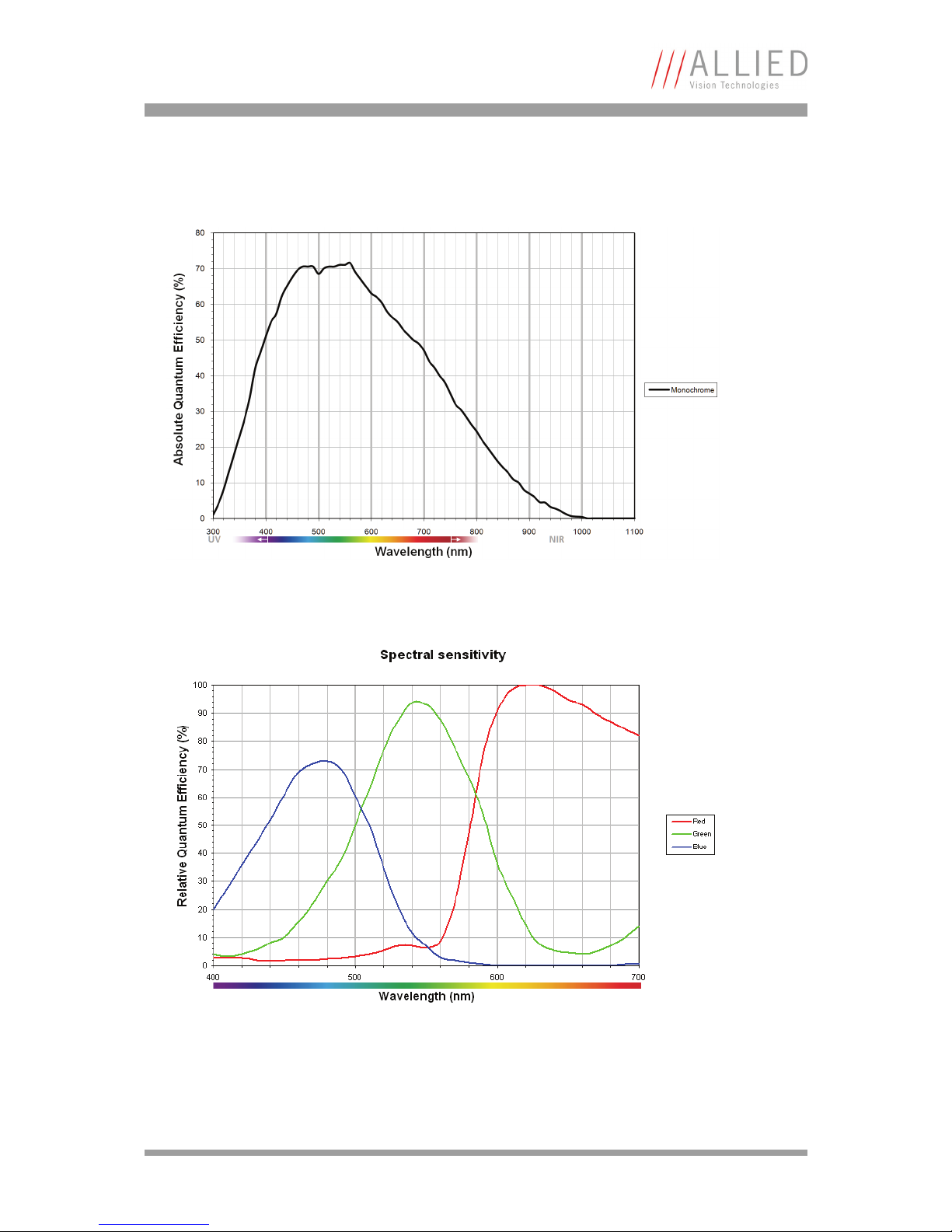
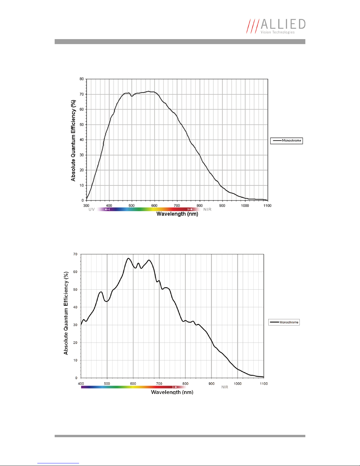
Spectral sensitivity
Figure 1: Spectral sensitivity of Bigeye P-132B / P-132B Cool
Figure 2: Spectral sensitivity of Bigeye P-132C Cool
Page 19
Specifications
Bigeye Technical Manual V2.0.0
19
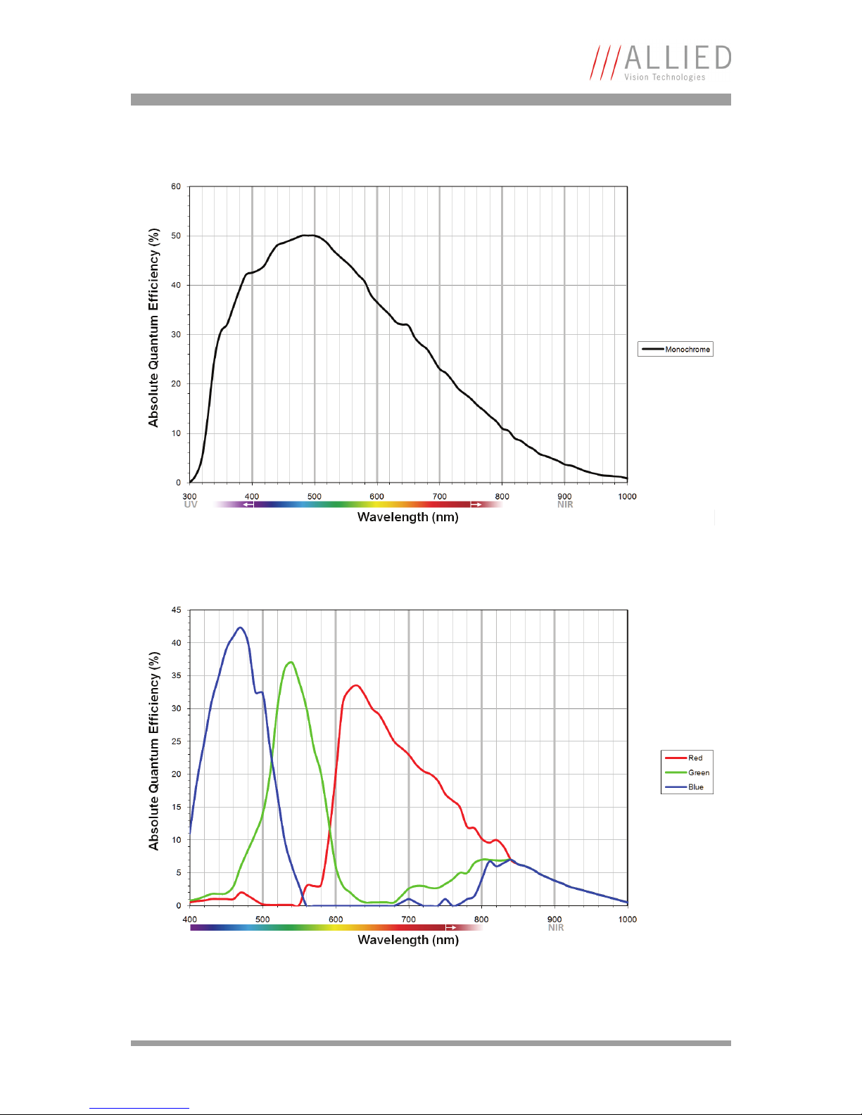
Figure 3: Spectral sensitivity of Bigeye P-132B Solar Cool
Figure 4: Spectral sensitivity of Bigeye P-629B Cool / P-629B Solar Cool
Page 20
Specifications
Bigeye Technical Manual V2.0.0
20
Figure 5: Spectral sensitivity of Bigeye P-1100B Cool
Figure 6: Spectral sensitivity of Bigeye P-1100C Cool
Page 21
Camera dimensions
Bigeye Technical Manual V2.0.0
21
Camera dimensions
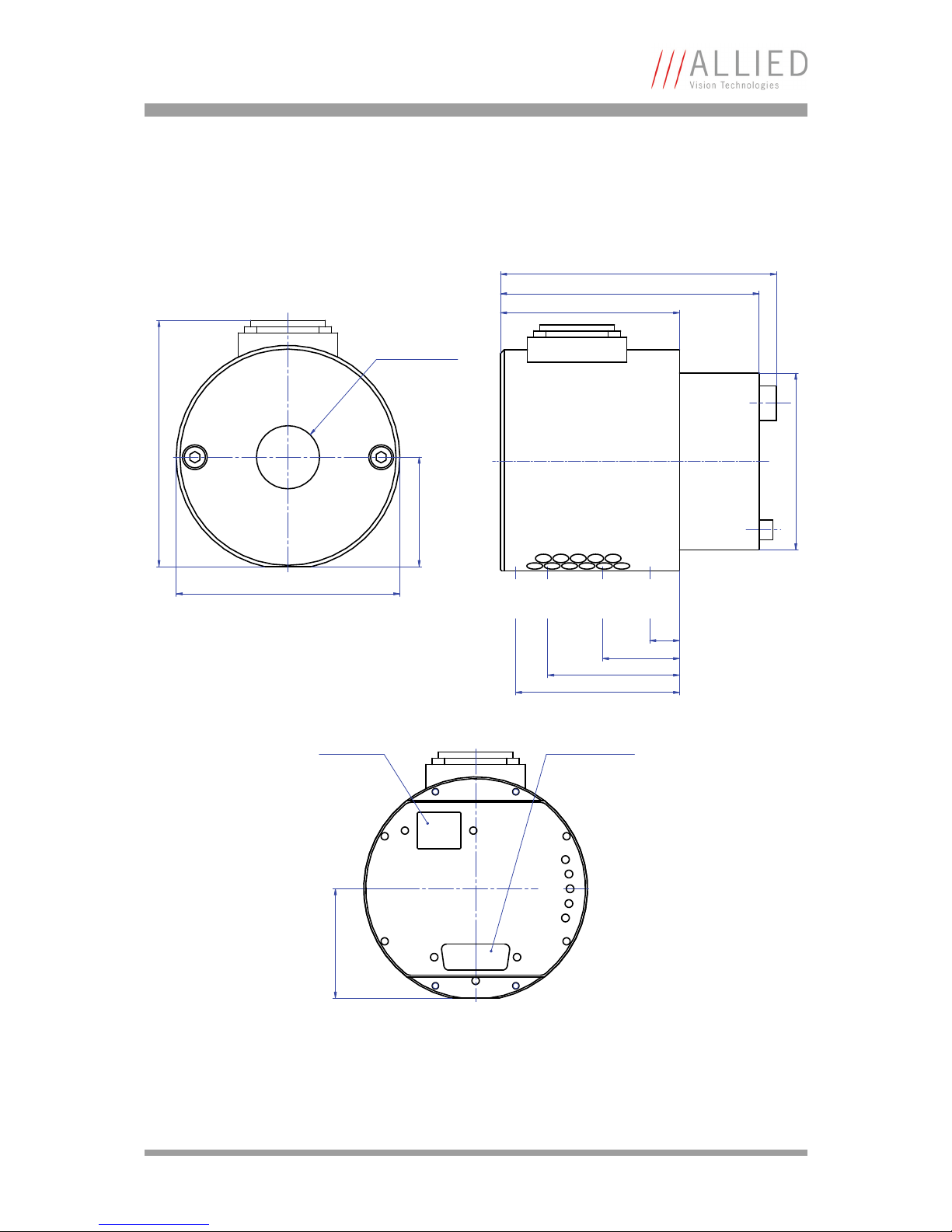
Bigeye P-132B
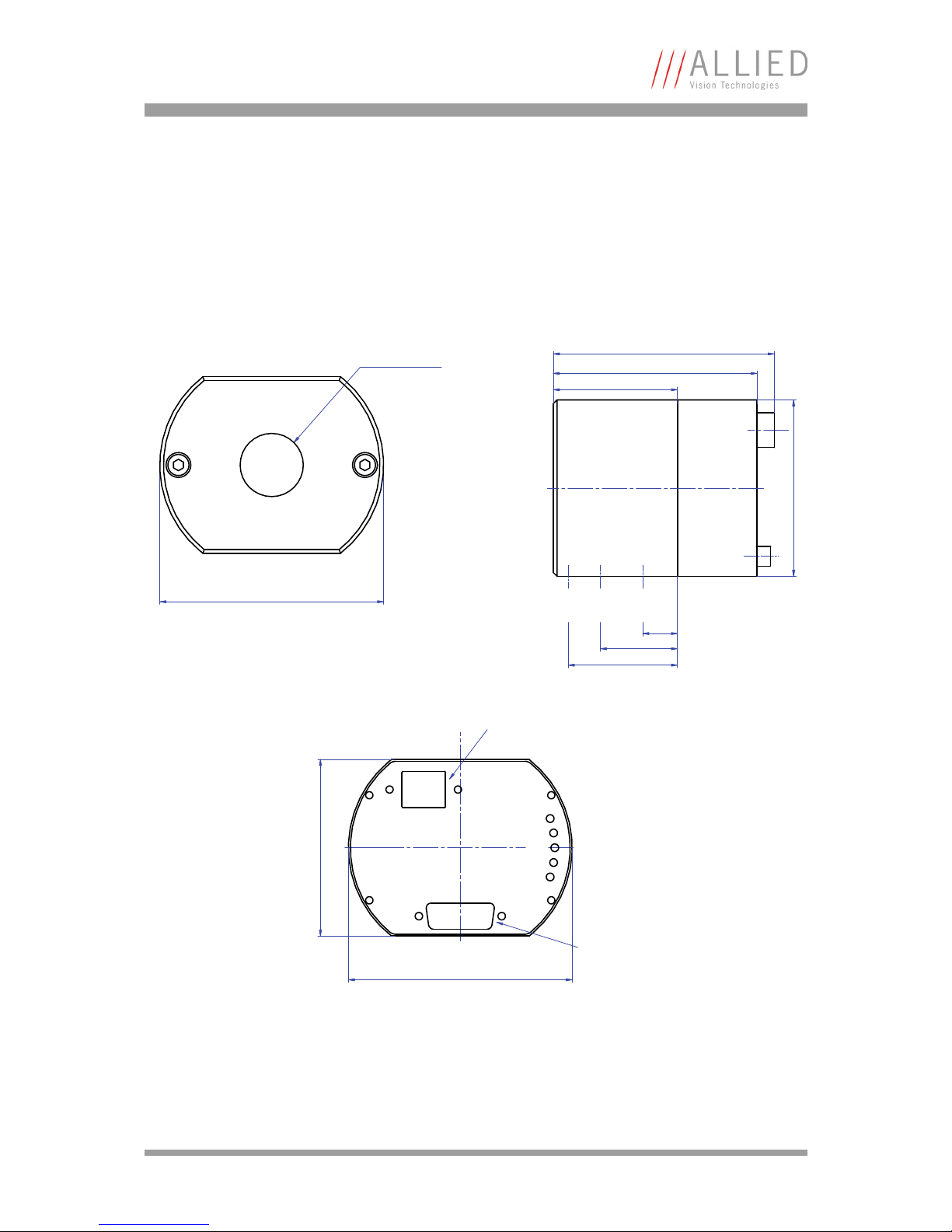
Figure 7: Camera dimensions: Bigeye P-132B (front/side/back)
C-Mount
Connection
Ø90
Power
L2
L3
L4
L5
Back view
Power / Control
connection
Gigabit Ethernet
connection
Ø90
71
UNC 1/4" UNC 1/4" M3
max. screw depth
7 mm 4,5 mm 3 mm
50
14
31
44
71
82
89
Page 22
Camera dimensions
Bigeye Technical Manual V2.0.0
22
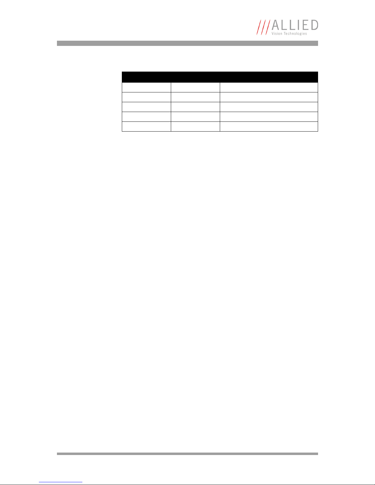
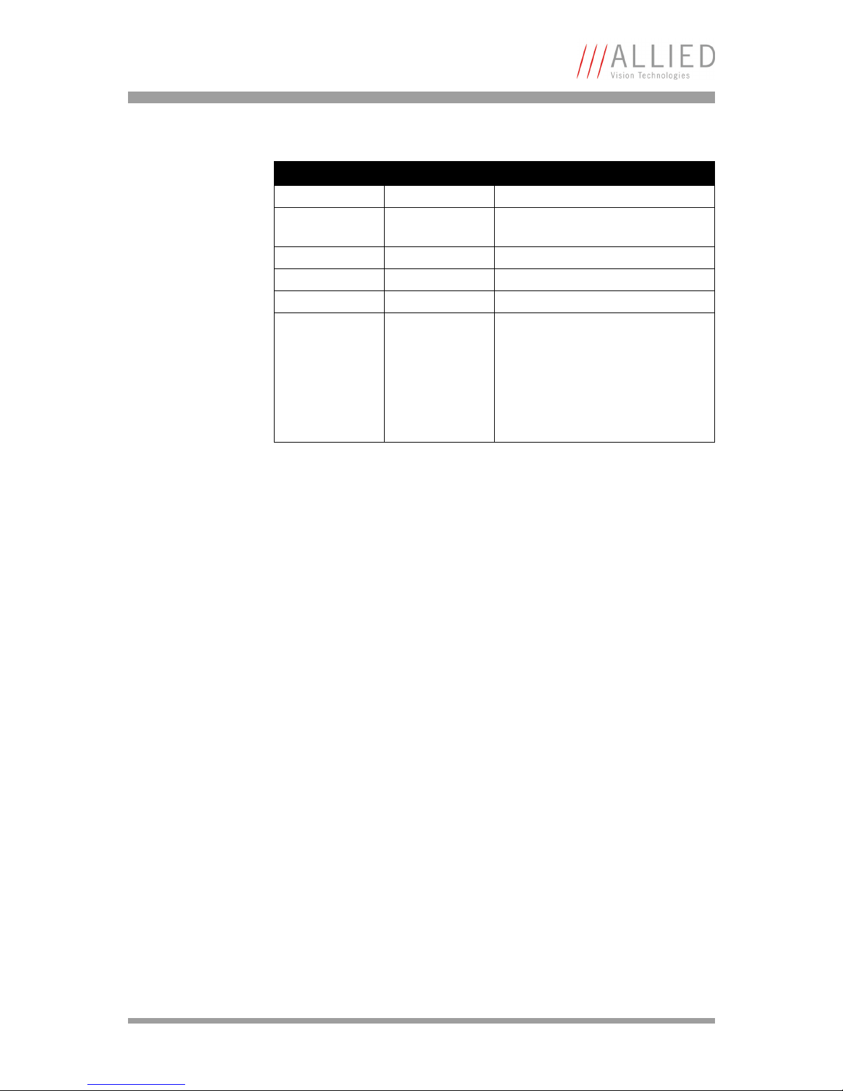
LED Color Description
L2 Red Camera is operational
L3 Red Image-on-demand mode
Power Green Power indicator
L4 Red Exposure input activity
L5 Red Frame output activity
Table 7: Description of LEDs: Bigeye P-132B
Page 23
Camera dimensions
Bigeye Technical Manual V2.0.0
23
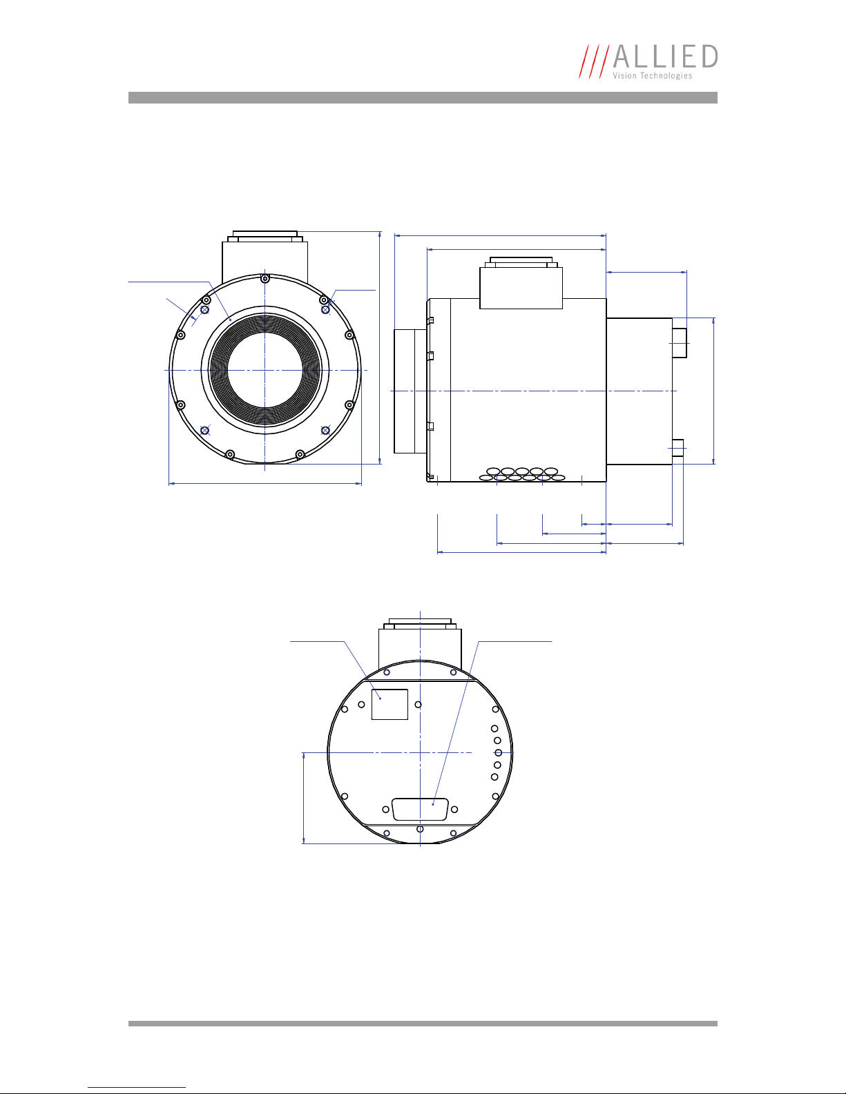
Bigeye P-132B/C Cool and P-132B Solar Cool
Figure 8: Camera dimensions: Bigeye P-132B/C Cool and P-132B Solar Cool (front/side/back)
Tem p
44
Power
L2
L3
L4
L5
Power / Control
connection
Gigabit Ethernet
connection
C-Mount Connection
Ø90
99
44
M6 UNC 1/4" UNC 1/4" M6
max. screw depth
7 mm 7 mm 7 mm 7 mm
12
31
53
66
72
71
104
111
Page 24
Camera dimensions
Bigeye Technical Manual V2.0.0
24
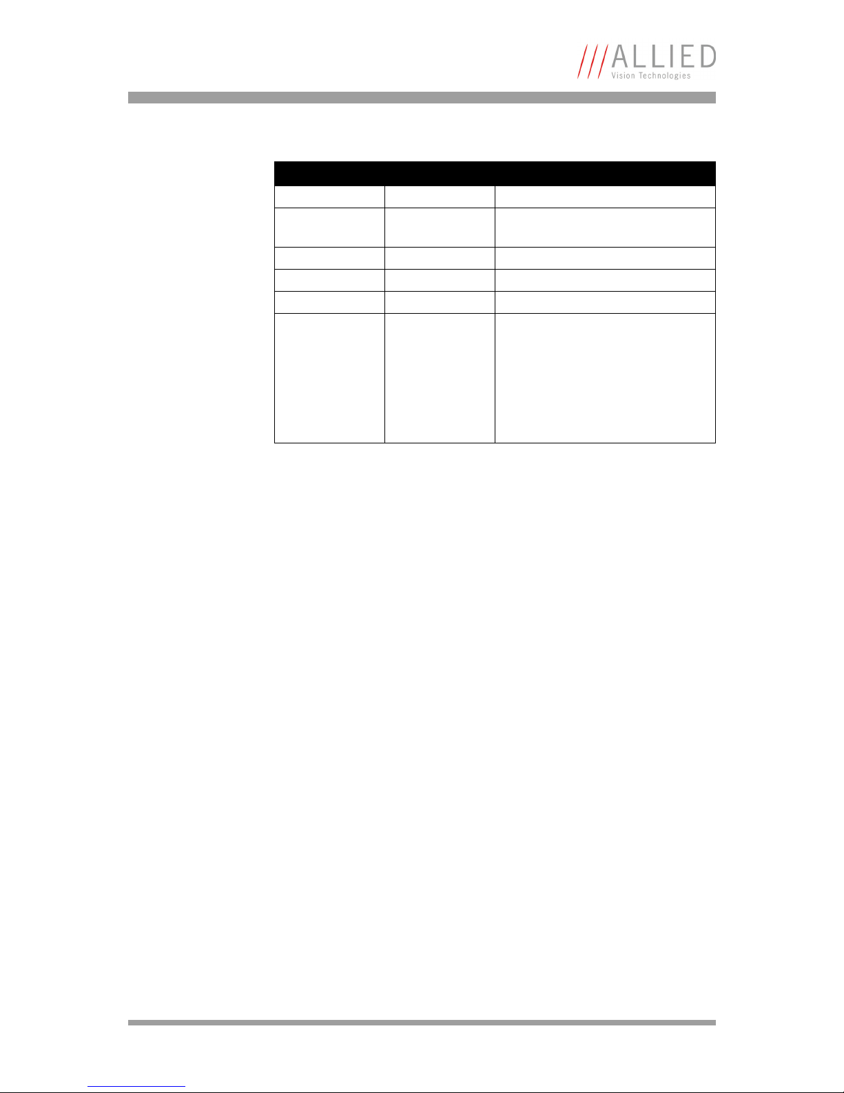
LED Color Description
L2 Red Camera is operational
L3 Red Temperature state (same function as
Temp LED)
Power Green Power indicator
L4 Red Exposure input activity
L5 Red Frame output activity
Temp Red Indicates that cooling temperature
has not reached approx. -20 °C.
If this LED is permanently lit during
operation, then the temperature of
the camera might be too high: Check
the ambient temperature and ensure
unhindered air flow.
Table 8: Description of LEDs: Bigeye P-132B/C Cool and P-132B Solar Cool
Page 25
Camera dimensions
Bigeye Technical Manual V2.0.0
25
Bigeye P-629B Cool / Solar Cool
Figure 9: Camera dimensions: Bigeye P-629B Cool / Solar Cool (front/side/back)
M6 UNC 1/4" UNC 1/4" M6
max. screw depth
8 mm 7 mm 7 mm 7 mm
12
31
53
82
87
102,75
32
37,5
39
71
R
4
0
M4 (4x)
depth 6mm
Ø90
F-Mount Connection
109
Tem p
44
Power
L2
L3
L4
L5
Power / Control
connection
Gigabit Ethernet
connection
Page 26
Camera dimensions
Bigeye Technical Manual V2.0.0
26
LED Color Description
L2 Red Camera is operational
L3 Red Temperature state (same function as
Temp LED)
Power Green Power indicator
L4 Red Exposure input activity
L5 Red Frame output activity
Temp Red Indicates that cooling temperature
has not reached approx. +5 °C.
If this LED is permanently lit during
operation, then the temperature of
the camera might be too high: Check
the ambient temperature and ensure
unhindered air flow.
Table 9: Description of LEDs: Bigeye P-629B Cool and Bigeye P-629B Solar Cool
Page 27
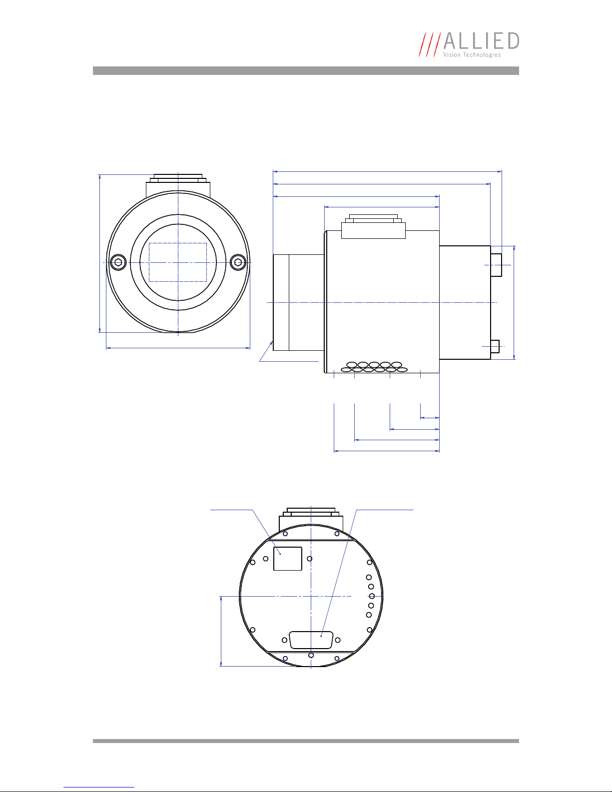
Camera dimensions
Bigeye Technical Manual V2.0.0
27
Bigeye P-1100B/C Cool
Figure 10: Camera dimensions: Bigeye P-1100B/C Cool (front/side/back)
Ø90
99
Tem p
44
Power
L2
L3
L4
L5
Power / Control
connection
Gigabit Ethernet
connection
M6 UNC 1/4" UNC 1/4" M6
max. screw depth
7 mm 7 mm 7 mm 7 mm
12
31
53
66
72
104
71
F-Mount Connection
136
143
Page 28
Camera dimensions
Bigeye Technical Manual V2.0.0
28
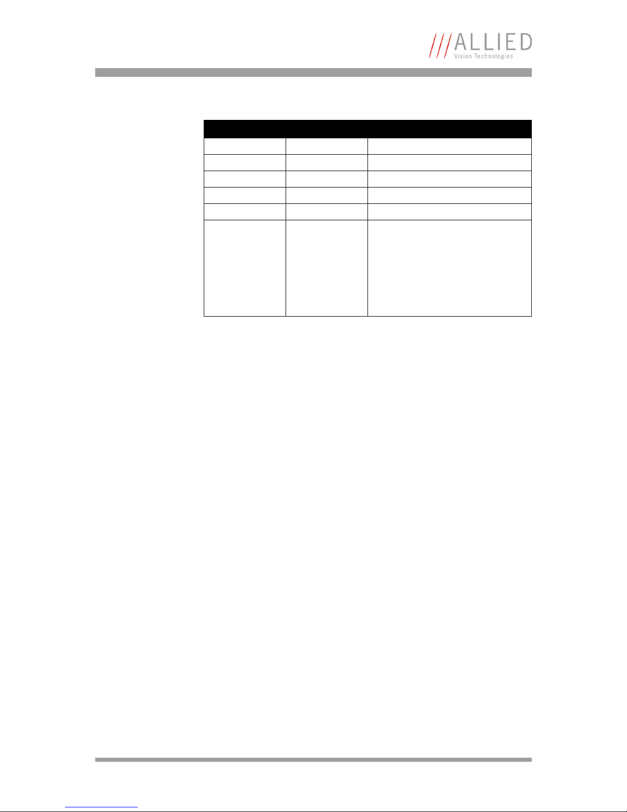
LED Color Description
L2 Red Camera is operational
L3 Red Image-on-demand mode
Power Green Power indicator
L4 Red Exposure input activity
L5 Red Frame output activity
Temp Red Indicates that cooling temperature
has not reached approx. 0 °C.
If this LED is permanently lit during
operation, then the temperature of
the camera might be too high: Check
the ambient temperature and ensure
unhindered air flow.
Table 10: Description of LEDs: Bigeye P-1100B/C Cool
Page 29
Camera interfaces
Bigeye Technical Manual V2.0.0
29
Camera interfaces
This chapter gives you information on the control junction, inputs and outputs
and trigger features.
Control junction
Camera I/O connector pin assignment (15-pin
D-Sub jack)
This jack is intended for the power supply as well as for controlling the camera
by the user.
www
For accessories like cables see:
http://www.alliedvisiontec.com/emea/products/
accessories/gige-accessories.html
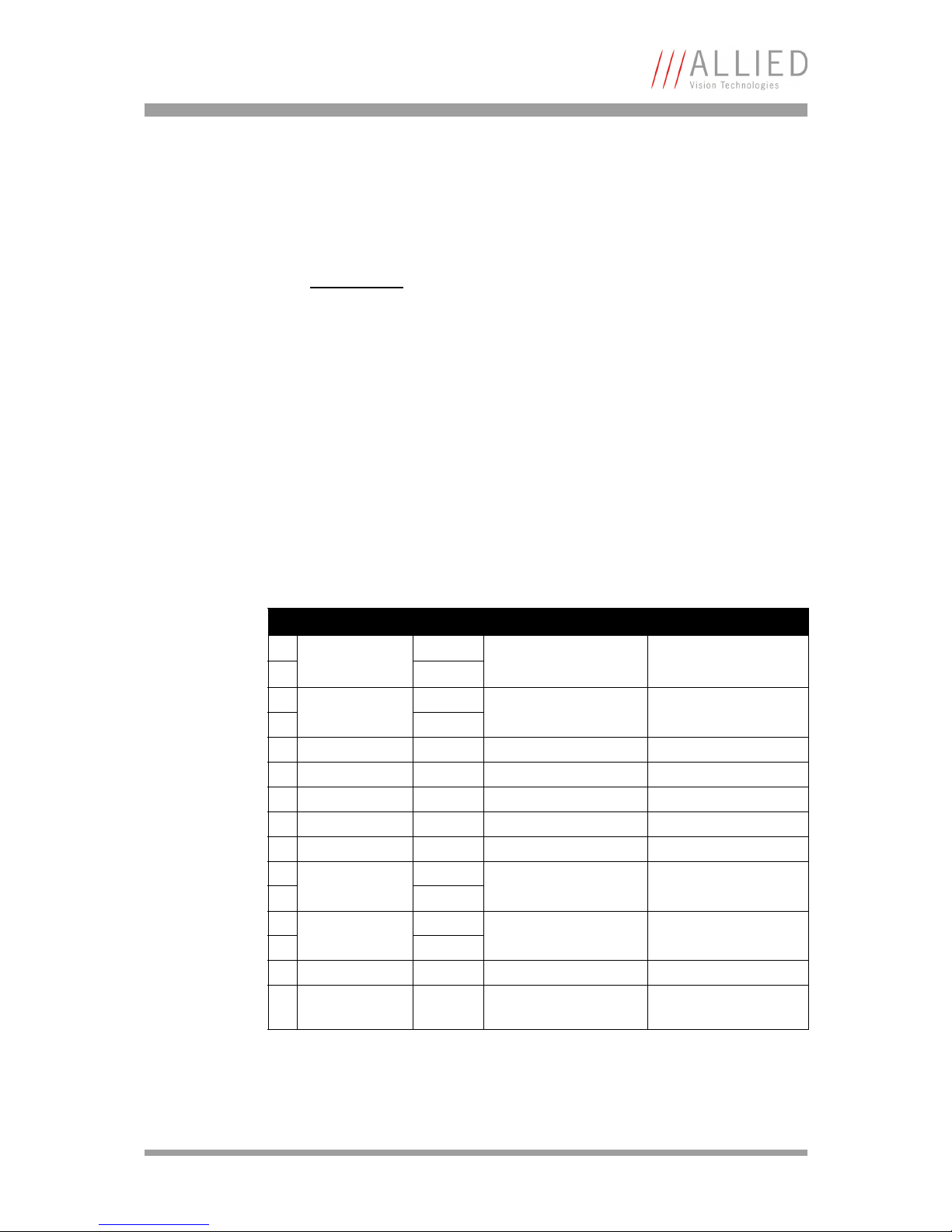
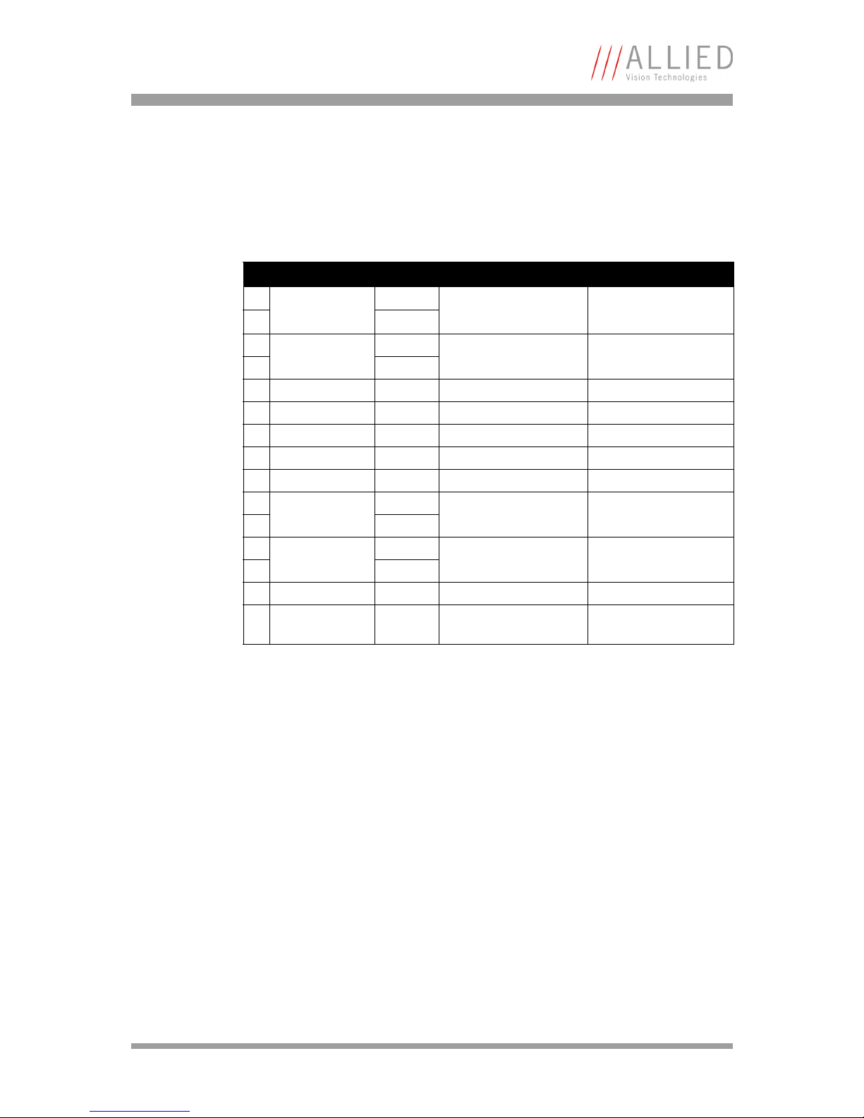
Figure 11: Camera I/O connector pin assignment (Bigeye P-132B/Cool/Solar Cool)
Bigeye P-132B / P-132B Cool / P-132B Solar Cool
Pin Signal Direction Level Description
1
External Power +12 V DC
Power supply
max. 2.8 A
2
3
External GND
4
5 --- Reserved
6 --- Reserved
7 RXD In RS232 Serial control
8 TXD Out RS232 Serial control
9 Mode input + 12V, 20 mA max. Internal pull-up resistor
10
Trigger input
12V, 20 mA max. Optocoupler input
11 +
12
Exposure output
12V, 20 mA max. Optocoupler output
13 +
14 Line-sync output Out 5 V (at no load) Active low
15 Frame-sync
output
Out 5 V (at no load) Active low
Page 30
Camera interfaces
Bigeye Technical Manual V2.0.0
30
This jack is intended for the power supply as well as for controlling the camera
by the user.
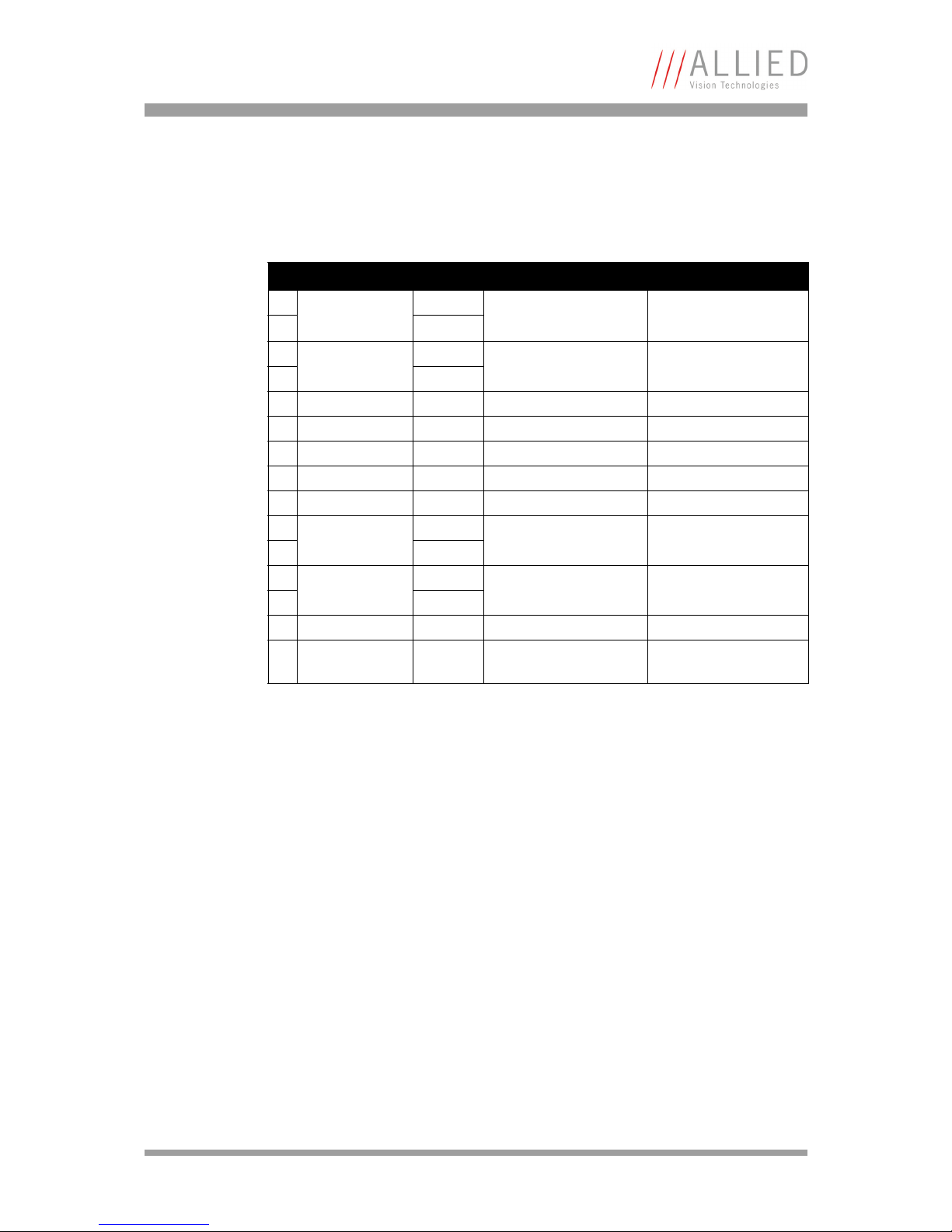
Figure 12: Camera I/O connector pin assignment (Bigeye P-629B Cool/Solar Cool)
Bigeye P-629B Cool/Solar Cool
Pin Signal Direction Level Description
1
External Power +12 V DC
Power supply
1.3 A ... max. 2.8 A
2
3
External GND
4
5 --- Reserved
6 --- Reserved
7 RXD In RS232 Serial control
8 TXD Out RS232 Serial control
9 Mode input + 12V, 20 mA max. Internal pull-up resistor
10
Trigger input
12V, 20 mA max. Optocoupler input
11 +
12
Exposure output
12V, 20 mA max. Optocoupler output
13 +
14 Line-sync output Out 5 V (at no load) Active low
15 Frame-sync
output
Out 5 V (at no load) Active low
Page 31
Camera interfaces
Bigeye Technical Manual V2.0.0
31
This jack is intended for the power supply as well as for controlling the camera
by the user.
Power supply (Pin 1-4)
Bigeye P-132 The camera requires 12 V +5% at a current capacity of maximum 0.8 A.
After attaining the end cooling temperature (- 20 °C) the current capacity goes
down to approx. 1.9 ... 2.3 A. The exact value also depends on the ambient temperature of the camera (not for Bigeye P-132B, because it is uncooled).
Bigeye P-629 The camera requires 12 V +5% at a current capacity of maximum 2.8 A.
After attaining the end cooling temperature (- 20 °C) the current capacity goes
down to approx. 1.3 ... 1.7 A. The exact value also depends on the ambient temperature of the camera.
Bigeye P-1100 The camera requires 12 V +5% at a current capacity of maximum 3.0 A.
Figure 13: Camera I/O connector pin assignment (Bigeye P-1100B/C Cool)
Bigeye P-1100B Cool / P-1100C Cool
Pin Signal Direction Level Description
1
External Power +12 V DC
Power supply
max. 3.0 A
2
3
External GND
4
5 --- Reserved
6 --- Reserved
7 RXD In RS232 Serial control
8 TXD Out RS232 Serial control
9 Mode input + 12V, 20 mA max. Internal pull-up resistor
10
Trigger input
12V, 20 mA max. Optocoupler input
11 +
12
Exposure output
12V, 20 mA max. Optocoupler output
13 +
14 Line-sync output Out 5 V (at no load) Active low
15 Frame-sync
output
Out 5 V (at no load) Active low
Page 32

Camera interfaces
Bigeye Technical Manual V2.0.0
32
Mode input (Pin 9)
The mode input provides a method for switching the camera between different
exposure control modes using an externally applied signal.
The indiviual function depends on the camera variant. The GigE Vision feature
AcquisitionControl/TriggerMode can be used to switch the mode via software.
Bigeye P-132 The mode input switches between the continuous free-running operation with
fixed 80 ms exposure time on the one hand and the image-on-demand mode
(IOD) on the other hand.
For long-term exposures the image-on-demand mode (IOD mode) generally has
to be activated. As a cooling of the sensor is only advantageous at longer exposure times, the cooling is generally only activated in the IOD mode. In the continuous mode the cooling is switched off. This feature allows to reduce the
power consumption of the camera during standby. After re-enabling the IOD
mode a cooling time of approx. 4 – 5 minutes is needed.
Input pin 9: open (or TTL high) continuous operation (cooling off)
GND (or TTL low) image-on-demand (cooling active)
Bigeye P-629 This camera variant is always in image-on-demand mode and does not support
continuous mode. Instead, this signal controls the behavior of the mechanical
shutter.
The shutter is automatically closed during the read-out of the sensor, in order
that no smear will take place. In case a pulsed light source is used, the shutter
needs not to be closed. This can be forced by the corresponding mode setting.
Input pin 9: open (or TTL high) shutter permanently open
GND (or TTL low) shutter closed during image output
Bigeye P-1100 The mode input switches between the continuous free-running operation with
fixed 635 ms exposure time on the one hand and the image-on-demand mode
(IOD mode) on the other hand.
For long-term exposures the image-on-demand mode (IOD mode) generally has
to be activated. As a cooling of the sensor is only advantageous at longer exposure times, the cooling is generally only activated in the IOD mode. In the continuous mode the cooling is switched off. This feature allows to reduce the
power consumption of the camera during standby. After re-enabling the IOD
mode a cooling time of approx. 4 – 5 minutes is needed.
After switching to image-on-demand mode a break of at least 635 ms has to
occur before the first image exposure can take place.
Input pin 9: open (or TTL high) continuous operation (cooling off)
GND (or TTL low) image-on-demand (cooling active)
Note
• For more information see Chapter Mode setting on page
39.
• The active state (externally low or TriggerMode = On) is
dominant, thus image-on-demand mode is active, if one
of either settings is.
Page 33
Camera interfaces
Bigeye Technical Manual V2.0.0
33
Trigger input (Pin 10, 11)
This input allows control of the electronic or electromechanical shutter by an
externally applied signal. It is necessary to switch the camera into image-ondemand mode to enable direct exposure control.
The signal is level-sensitive, thus the HIGH duration directly dictates the exposure time of the camera.
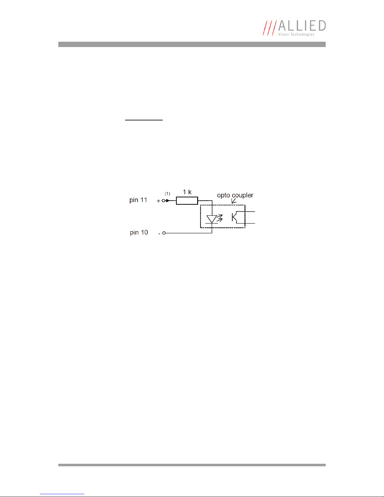
The current through the opto coupler (1) should be greater than 1 mA and not
exceed 20 mA:
5 … 12V (HIGH) Active exposure (only valid during IOD mode)
<0.8 V (LOW) Inactive (falling edge starts frame output)
Note
For more information on image-on-demand mode: see Chapter
Mode setting on page 39.
Figure 14: Trigger input diagram
Page 34
Camera interfaces
Bigeye Technical Manual V2.0.0
34
Exposure output (Pin 12, 13)
Bigeye P-132 The exposure output indicates the active exposure time of the sensor.
Usage: synchronize an external strobe light source.
At the end of the exposure this output stays active approx. 76 μs (1 line) longer
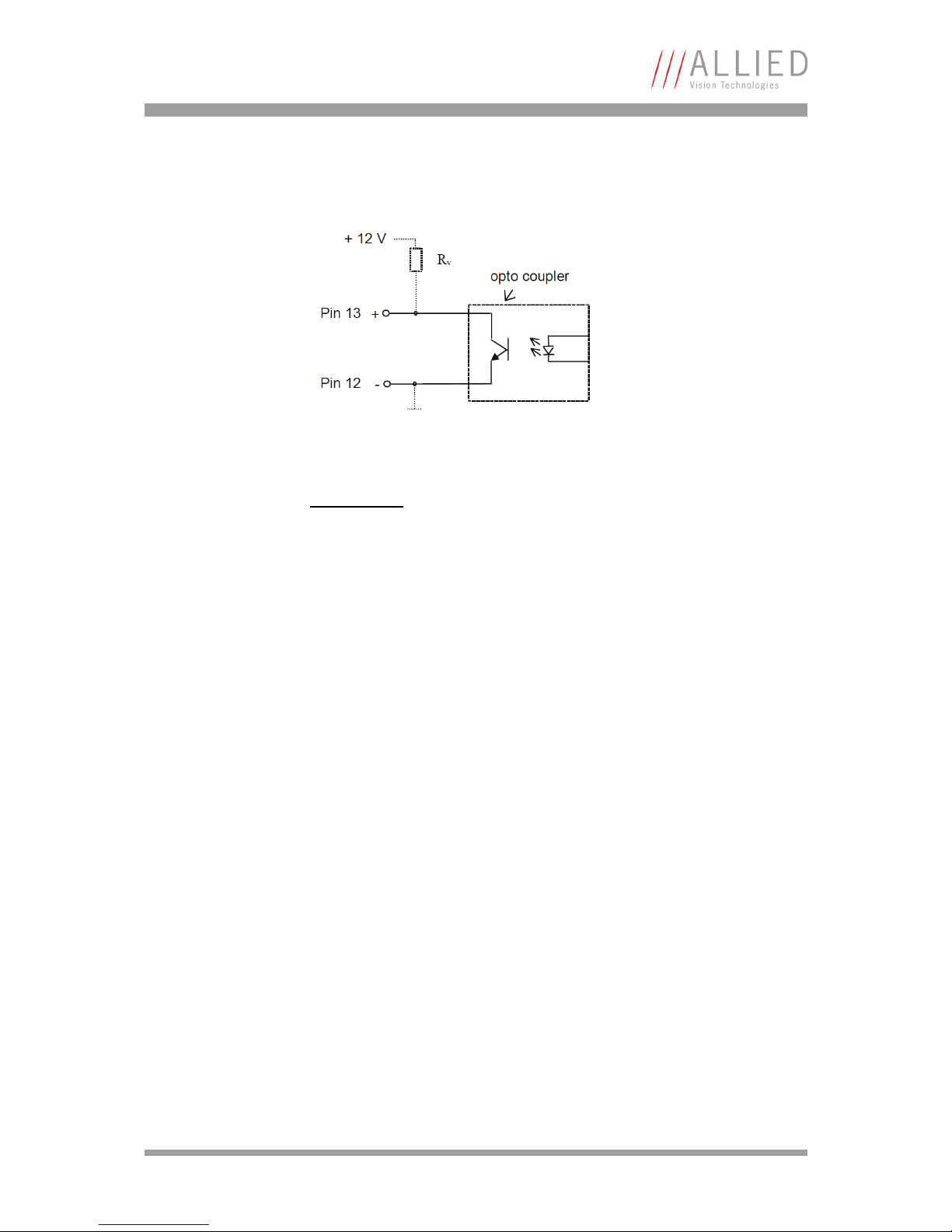
than the real exposure. The active exposure is indicated in the image-ondemand operation also by the LED L4 on the backside of the camera. For using
the exposure output an external resistor R
v
according to the drawing has to be
applied.
After the end of image exposure the 1024 active lines of the image are transmitted. This image output is displayed by LED L5 at the backside of the camera.
Bigeye P-629 The exposure output indicates the active exposure time of the sensor.
Usage: synchronize an external strobe light source.
At the end of the exposure this output stays active approx. 658 μs (1 line) longer than the real exposure. The active exposure is indicated in the image-ondemand operation also by the LED L4 on the backside of the camera. For using
the exposure output an external resistor R
v
according to the drawing has to be
applied.
After the end of image exposure the 2048 active lines of the image are transmitted. This image output is displayed by LED L5 at the backside of the camera.
Bigeye P-1100 The exposure output indicates the active exposure time of the sensor.
Usage: synchronize an external strobe light source.
Figure 15: Exposure output
Caution
The current which flows through the optocoupler should not
exceed 20 mA (at 12 V R
v
600 ).
Page 35
Camera interfaces
Bigeye Technical Manual V2.0.0
35
At the end of the exposure this output stays active approx. 232 μs (1 line) longer than the real exposure. The active exposure is indicated in the image-ondemand operation also by the LED L4 on the backside of the camera. For using
the exposure output an external resistor R
v
according to the drawing has to be
applied.
After the end of image exposure the 2680 active lines of the image are transmitted. This image output is displayed by LED L5 at the backside of the camera.
Line-sync output (Pin 14)
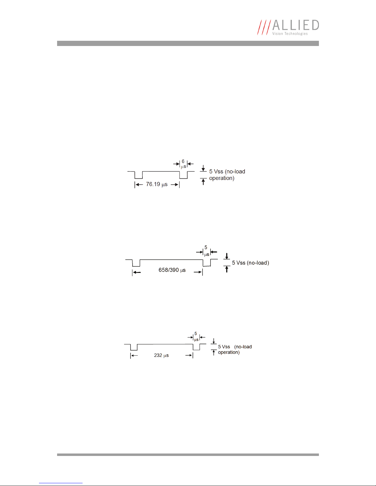
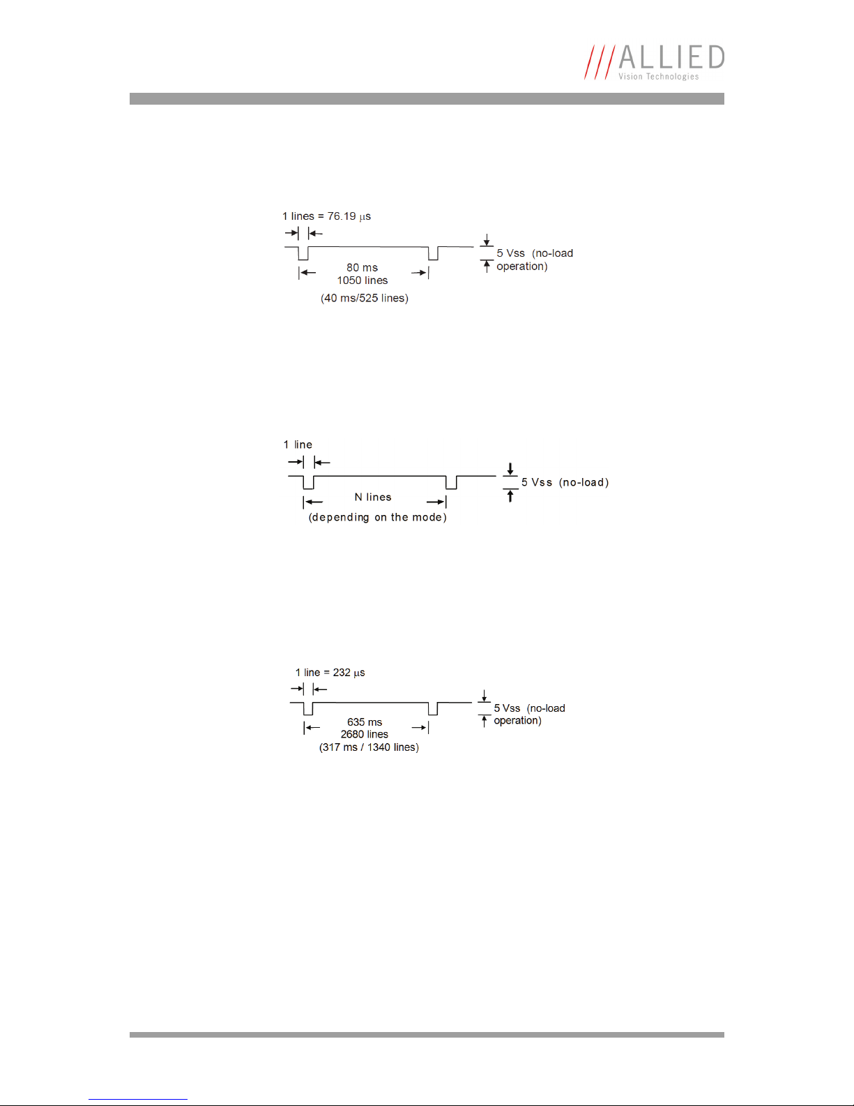
The line-sync output (active low) supplies approx. 1200 mV at a termination
with 75 .
The line-sync output (active low) supplies approx. 900 mV at a termination with
75 .
The line-sync output (active low) supplies approx. 1200 mV at a termination
with 75 .
Figure 16: Line-sync output (Bigeye P-132)
Figure 17: Line-sync output (Bigeye P-629)
Figure 18: Line-sync output (Bigeye P-1100)
Bigeye P-132
Bigeye P-629
Bigeye P-1100
Page 36
Camera interfaces
Bigeye Technical Manual V2.0.0
36
Frame-sync output (Pin 15)
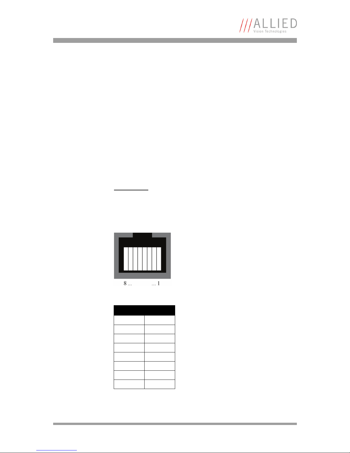
Bigeye P-132 The frame-sync output is only active in continuous operation.
The frame-sync output (active low) supplies approx. 1200 mV at a termination
with 75 .
Bigeye P-629 The frame-sync output becomes active at the beginning of an image output.
The frame-sync-output (active low) supplies approx. 900 mV at a termination
with 75 .
Bigeye P-1100 The frame-sync output is only active in continuous operation.
The frame-sync-output (active low) supplies approx. 1200 mV at a termination
with 75 .
Figure 19: Frame-sync output (Bigeye P-132)
Figure 20: Frame-sync output (Bigeye P-629)
Figure 21: Line-sync output (Bigeye P-1100)
Page 37
Camera interfaces
Bigeye Technical Manual V2.0.0
37
GigE interface
The Bigeye cameras are equipped with a 1000Base-T Ethernet interface. The
data connection between camera and PC can be established via a standard
CAT5e patch cable to a 1000Base-T compatible Ethernet adapter card.
To control the Bigeye cameras use the AVT AcquireControl software or any GigE
Vision V1.2 compliant 3rd party software package.
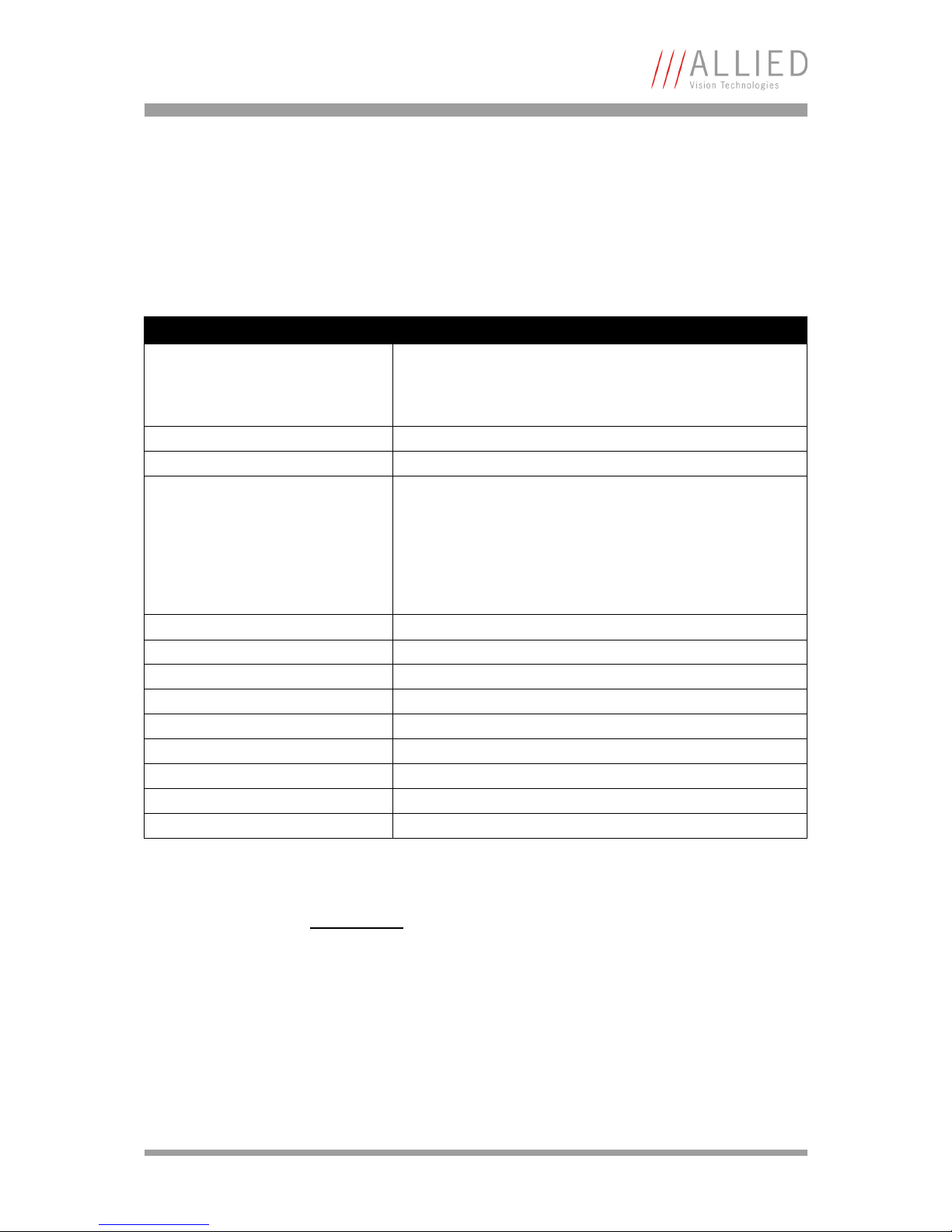
Pin assignment of Gigabit Ethernet jack
The Bigeye P-008/032 cameras are equipped with a 1000Base-T Ethernet interface (RJ-45 connector). The data connection between camera and PC can be
established via a standard CAT5e patch cable.
Note
For more information see the Pleora iPORT PT1000-VB
Documentation.
Figure 22: Front view of the Gigabit Ethernet jack
Pin Signal
1D1+
2D1–
3D2+
4D3+
5D3-
6D2-
7D4+
8D4–
Table 11: GigE jack: pin assignment
Page 38
Camera interfaces
Bigeye Technical Manual V2.0.0
38
Exposure control
Exposure time and dark time can be controlled using the features from the
branch AcquisitionControl of the GigE Vision feature tree.
tbd: More detailed explanation of timing constraints (regarding frame rate and
exposure time) of the individual camera models.
AcquisitionControl
Feature Description
AcquisitionMode This feature controls the acquisition mode of the software. This
feature works independently (!) of the chosen camera mode
(Continuous, IOD hardware trigger, IOD hardware timer). It
describes how many frames should be acquired.
AcquisitionStart Starts the image acquisition of the camera.
AcquisitionStop Stops the image acquisition of the camera.
TriggerMode Modifies the trigger mode of the camera. When the trigger mode
is “Off”, the camera will generate frames independently. When
the trigger mode is “On” the camera is switched to the so called
IOD (Image On Demand) mode. In this mode the camera waits for
an external trigger signal or an timer pulse generated internally.
To control exposure and dark time trigger mode must be switched
to “On”.
ExposureMode Start or stop the internal exposure signal timer.
ExposureTime This feature is used to set the Exposure time (in microseconds).
ExposureTimeAbs This feature is used to set the Exposure time (in microseconds).
ExposureTimeGranularity Exposure time granularity
ExposureTimeAbsMs This feature is used to set the Exposure time (in milliseconds).
DarkTime This feature is used to set the Dark time (in microseconds).
DarkTimeAbs This feature is used to set the Dark time (in microseconds).
DarkTimeGranularity Dark time granularity
DarkTimeAbsMs This feature is used to set the Dark time (in milliseconds).
Table 12: Camera standard feature: AcquisitionControl
Note
Bigeye P-132, Bigeye P-1100: The TriggerMode feature has to
be set to On and the timer has to be enabled via ExposureMode
in order to control the exposure.
Page 39
Camera interfaces
Bigeye Technical Manual V2.0.0
39
Beside the internal exposure control capabilities also direct exposure control
by an externally applied signal is possible. In this case the ExposureMode has
to be configured to Off to deactivate the internal timer.
Mode setting
The GigE Vision feature AcquisitionControl/TriggerMode setting provides a
method for switching the camera between different exposure control modes.
The individual function depends on the camera variant.
The Mode input (Pin 9) can be used to control this setting using an external signal.
Note
Bigeye P-629: The timer has to be enabled via the
ExposureMode feature in order to control the exposure. Set the
TriggerMode feature to On if the electromechanical shutter
operation is needed, otherwise it will stay permanently open.
Note
For more information see Chapter Mode input (Pin 9) on page
32.
Note
The active state (externally low at pin 9 or TriggerMode = On) is
dominant, thus image-on-demand is active if one of either settings is.
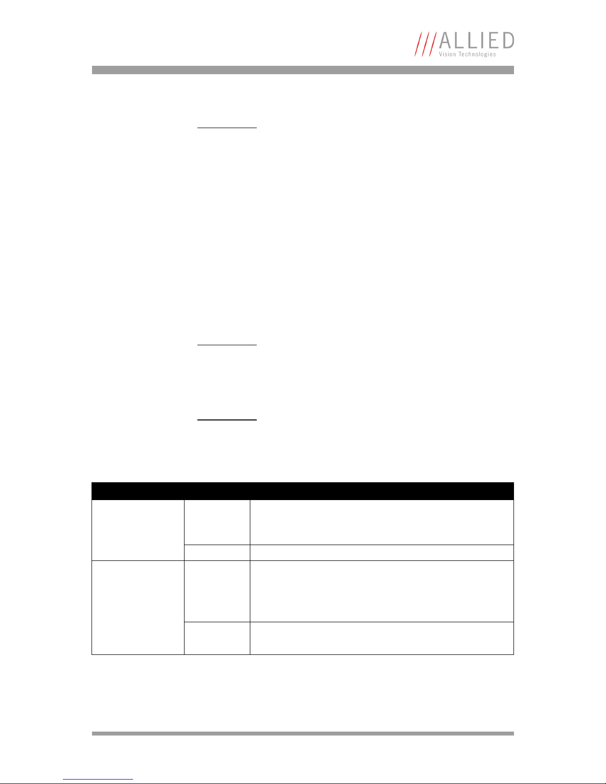
Camera TriggerMode Description
Bigeye P-132B On Image-on-demand mode.
Exposure control via ExposureTime and DarkTime features
(ExposureMode = Timed) or externally (ExposureMode = Off).
Off Continuous mode with fixed exposure time and frame rate.
Bigeye P-132x Cool On Image-on-demand mode.
Peltier cooling active.
Exposure control via ExposureTime and DarkTime features
(ExposureMode = Timed) or externally (ExposureMode = Off).
Off Continuous mode with fixed exposure time and frame rate.
Peltier cooling inactive (power saving).
Table 13: TriggerMode
Page 40
Camera interfaces
Bigeye Technical Manual V2.0.0
40
Binning
Each Bigeye camera variant supports one distinct binning configuration (either
1 x 2 or 2 x 2) which can be switched on or off.
This is controlled using the GigE Vision features BinningVertical and
BinningHorizontal from the ImageSizeControl branch of the feature tree.
In the case of 2 x 2 binning the two features are coupled. This if one of
BinningVertical or BinningHorizontal is changed, the counterpart is
automatically changed, too.
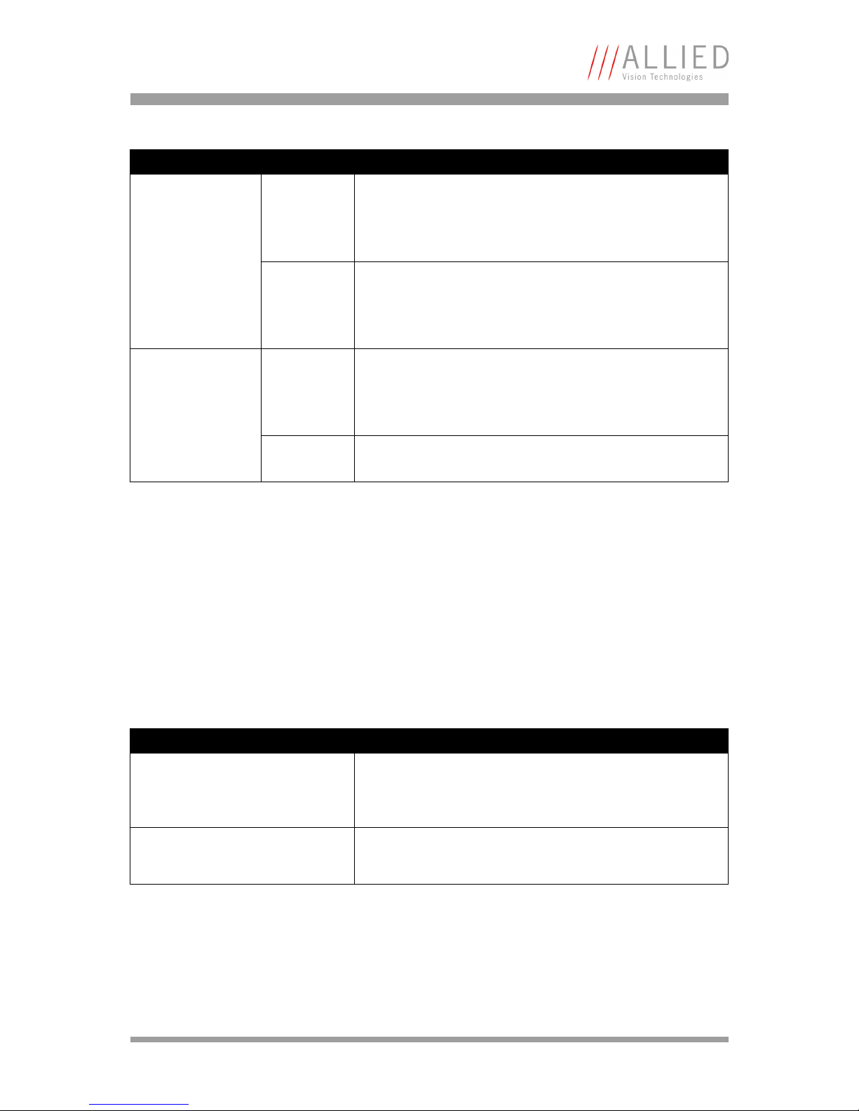
ImageSizeControl
Bigeye P-629 On Image-on-demand mode.
Electromechanical shutter enabled.
Exposure control via ExposureTime and DarkTime features
(ExposureMode = Timed) or externally (ExposureMode = Off).
Off Image-on-demand mode.
Electromechanical shutter always open.
Exposure control via ExposureTime and DarkTime features
(ExposureMode = Timed) or externally (ExposureMode = Off).
Bigeye P-1100 On Image-on-deman mode.
Peltier cooling active.
Exposure control via ExposureTime and DarkTime features
(ExposureMode = Timed) or externally (ExposureMode = Off).
Off Continuous mode with fixed exposure time and frame rate.
Peltier cooling inactive (power saving).
Feature Description
BinningVertical Number of horizontal photo-sensitive cells to combine together.
This increases the intensity (or signal-to-noise ratio) of the
pixels and reduces the horizontal resolution (width) of the
image.
BinningHorizontal Number of vertical photo-sensitive cells to combine together.
This increases the intensity (or signal-to-noise ratio) of the
pixels and reduces the vertical resolution (height) of the image.
Table 14: Camera standard feature: ImageSizeControl
Camera TriggerMode Description
Table 13: TriggerMode
Page 41

Camera interfaces
Bigeye Technical Manual V2.0.0
41
Gain
Use the GigE Vision feature Gain from the feature branch AnalogControls to
change the analog gain setting.
Value 1 selects 0 dB gain and Value 2 switches to +6 dB gain.
AnalogControls
Feature Description
Gain This feature controls the selected gain as a raw integer value.
Table 15: Camera standard feature: AnalogControls
Page 42
Appendix
Bigeye Technical Manual V2.0.0
42
Appendix
GigE Vision feature description for AVT Bigeye
cameras
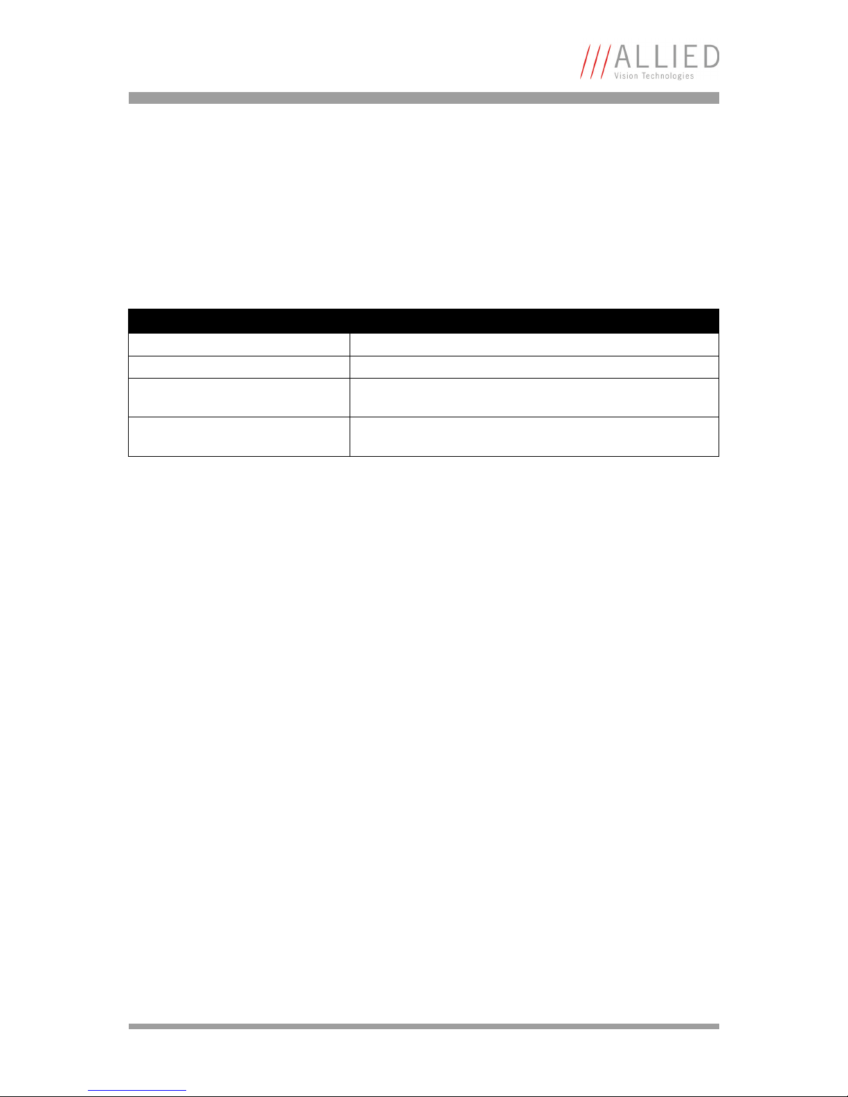
DeviceInformation
Feature Description
DeviceModeName Name of the attached camera model.
DeviceID Unique 32 bit device ID of the AVT camera model.
DeviceUserID User ID field. This field can be accessed (R/W) by the user to store
an additional device identifier.
DeviceScanType This feature specifies the scan type of the sensor (Areascan or
Linescan).
Table 16: Standard: DeviceInformation
Page 43
Appendix
Bigeye Technical Manual V2.0.0
43
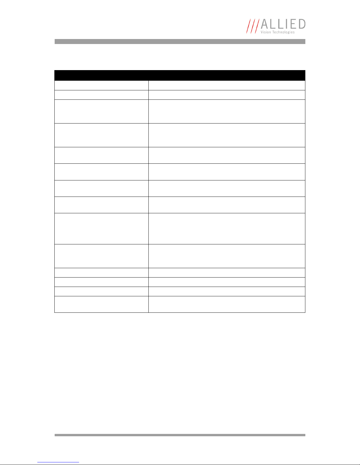
ImageSizeControl
Feature Description
SensorWidth Maximum width of the sensor in pixels.
SensorHeight Maximum height of the sensor in pixels.
WidthMax This feature represents the maximum width (in pixels) of the
image after horizontal binning, decimation or any other function
changing the horizontal dimensions of the image.
HeightMax This feature represents the maximum height (in pixels) of the
image after vertical binning, decimation or any other function
changing the vertical dimensions of the image.
Width This feature represents the actual image width expelled by the
camera (in pixels).
Height This feature represents the actual image height expelled by the
camera (in pixels).
OffsetX This feature represents the horizontal offset from the origin to
the AOI (in pixels).
OffsetY This feature represents the vertical offset from the origin to the
AOI (in pixels).
BinningVertical Number of horizontal photo-sensitive cells to combine together.
This increases the intensity (or signal-to-noise ratio) of the
pixels and reduces the horizontal resolution (width) of the
image.
BinningHorizontal Number of vertical photo-sensitive cells to combine together.
This increases the intensity (or signal-to-noise ratio) of the
pixels and reduces the vertical resolution (height) of the image.
DecimationHorizontal Unused.
DecimationVertical Unused.
PixelFormat List with all available pixel formats of the camera, e.g. MONO12.
TestImageSelector Enables or disables the internal test image generator of the
camera.
Table 17: Camera standard feature: ImageSizeControl
Page 44
Appendix
Bigeye Technical Manual V2.0.0
44
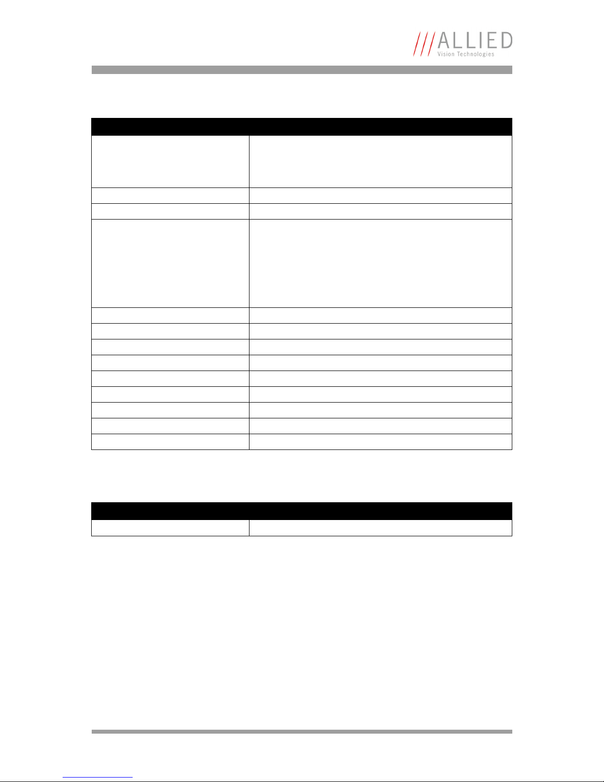
AcquisitionControl
AnalogControls
Feature Description
AcquisitionMode This feature controls the acquisition mode of the software. This
feature works independently (!) of the chosen camera mode
(Continuous, IOD hardware trigger, IOD hardware timer). It
describes how many frames should be acquired.
AcquisitionStart Starts the image acquisition of the camera.
AcquisitionStop Stops the image acquisition of the camera.
TriggerMode Modifies the trigger mode of the camera. When the trigger mode
is “Off”, the camera will generate frames independently. When
the trigger mode is “On” the camera is switched to the so called
IOD (image-on-demand) mode. In this mode the camera waits
for an external trigger signal or an timer pulse generated
internally. To control exposure and dark time, trigger mode must
be switched to “On”.
ExposureMode Start or stop the internal exposure signal timer.
ExposureTime This feature is used to set the Exposure time (in microseconds).
ExposureTimeAbs This feature is used to set the Exposure time (in microseconds).
ExposureTimeGranularity Exposure time granularity.
ExposureTimeAbsMs This feature is used to set the Exposure time (in milliseconds).
DarkTime This feature is used to set the Dark time (in microseconds).
DarkTimeAbs This feature is used to set the Dark time (in microseconds).
DarkTimeGranularity Dark time granularity.
DarkTimeAbsMs This feature is used to set the Dark time (in milliseconds).
Table 18: Camera standard feature: AcquisitionControl
Feature Description
Gain This feature controls the selected gain as a raw integer value.
Table 19: Camera standard feature: AnalogControls
Page 45
Appendix
Bigeye Technical Manual V2.0.0
45
CameraSpecialFeatures
This feature is not available for Bigeye P-1100B/C Cool and Bigeye P-132B.
Feature Description
CameraTemperatureState Camera temperature state.
0 = The camera temperature is OK.
1 = The camera temperature is outside the optimum range.
CameraTemperatureStateReg Camera temperature state register.
QueryCameraTemperatureState Query camera temperature state.
Table 20: Camera special feature: Camera temperature
Page 46

Bigeye Technical Manual V2.0.0
46
Index
Index
A
AcquisitionControl............................... 38, 44
AnalogControls ........................................ 44
B
Binning .................................................. 40
BinningHorizontal .................................... 43
BinningVertical ........................................ 43
C
camera dimensions .....................21, 23, 25, 27
camera interfaces ..................................... 29
CameraSpecialFeatures.............................. 45
CameraTemperatureState ........................... 45
CameraTemperatureStateReg ...................... 45
CE............................................................ 9
Conformity ................................................ 9
Contacting ................................................ 5
Control junction ....................................... 29
D
declaration of conformity............................. 9
DeviceInformation.................................... 42
document history ....................................... 6
E
Exposure control ...................................... 38
Exposure output.........................29
, 30, 31, 34
External GND ................................. 29
, 30, 31
External Power............................... 29
, 30, 31
F
FCC Class B ................................................ 9
Frame-sync output......................29
, 30, 31, 36
G
Gain.................................................. 41, 44
Gigabit Ethernet jack................................. 37
GigE interface .......................................... 37
GigE jack pin assignment............................ 37
GigE Vision
feature description.............................. 42
I
ImageSizeControl ................................ 40, 43
I/O connector .......................................... 29
L
Legal notice .............................................. 2
Line-sync output ........................29
, 30, 31, 35
M
Mode input.............................................. 32
Mode input (Pin 9).................................... 39
Mode setting ........................................... 39
P
Pin assignment
Gigabit Ethernet jack ........................... 37
PoE........................................................ 10
Power supply ........................................... 31
Q
QueryCameraTemperatureState ................... 45
R
RJ-45..................................................... 37
RoHS (2002/95/EC) .................................... 9
S
Specifications
Bigeye P-1100B/C Cool ........................ 16
Bigeye P-132B.................................... 10
Bigeye P-132B Cool ............................. 12
Bigeye P-629B Cool ............................. 14
Bigeye P-629B Solar Cool ..................... 14
specifications .......................................... 10
Spectral Sensitivity
Bigeye P-629B Solar Cool ................ 19
, 20
Spectral sensitivity ................................... 18
Page 47

Bigeye Technical Manual V2.0.0
47
Index
Bigeye P-132B.................................... 18
Bigeye P-132B Cool ............................. 18
Bigeye P-132B Solar Cool ..................... 19
Bigeye P-629B Cool ........................ 19
, 20
styles ....................................................... 7
Support .................................................... 5
symbols .................................................... 7
T
Technical information.................................. 5
Trigger input .............................29
, 30, 31, 33
TriggerMode ............................................ 39
 Loading...