

Page 1
29JR
VARIOCLIP
MANUAL
Page 2
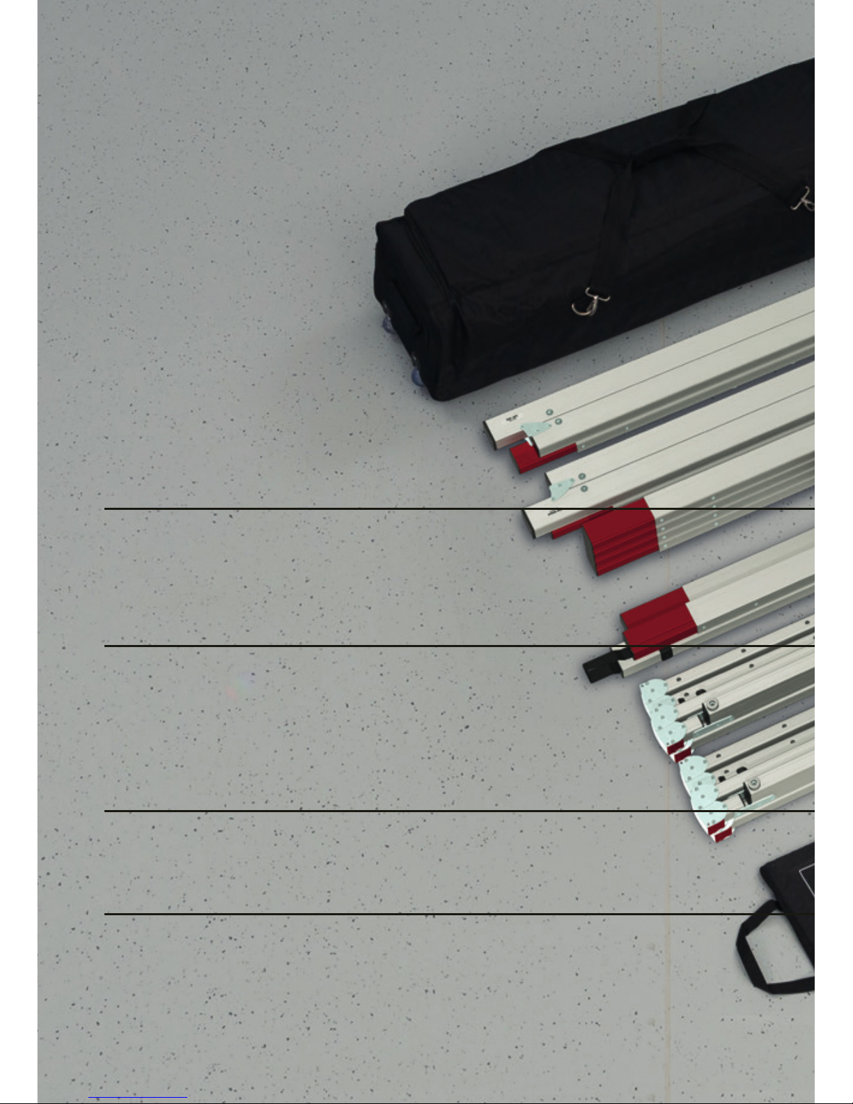
FOLDABLE LEGS
Standard delivery AT32/64.
According to the size of the projection screen ve dierent leg
types are available.
WING SCREWS
Yellow bag for wing screws and leg connectors.
PROJECTION SCREEN BAG
Lined storage bag for projection screen
CENTRE SUPPORT
Consists of plug in elements with interlocking
and safety bolts. Adaptable to any frame size.
Page 3
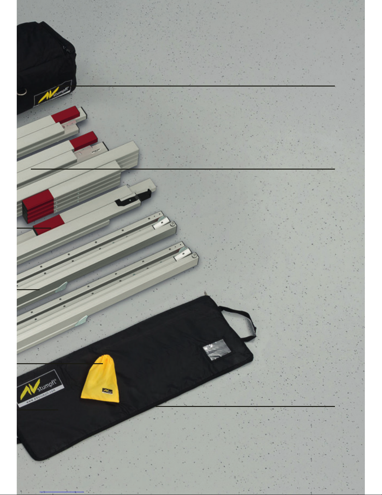
SOFTBAG WITH WHEELS
padded , tearproof nylonbag
with wheels and carrying straps
small 128x25x30 cm
big 133x31x35 cm
ASSEMBLY INSTRUCTION
FRAME VARIOCLIP
Modular plug-in frame system
Basic frame (4 corners 210x210 cm or
210x160 cm) folded, standard and
supplementary frame components
Hardened aluminum alloy guarantees
highest stability at lowest product weight.
Page 4
QUALITY AND SAFETY:
This projection screen is in accordance with the safety regulations in DIN standard 19045 and DIN 56950-
40. Thescreen fabric is comply with DIN 4102 part 1 and the specications of the according data sheet.
For the technical details and projection-specic material parameters please refer to the
corresponding product data sheet. www.AVstump.com/projectionmaterials
WARRANTY:
The warranty period for production deciencies is 5 years for the frame elements and 24 months
for the projection surface. Mobile projection screens are developed for indoor use only. Any damage and
consequential damage caused by outdoor use is not covered by warranty.
The general terms and conditions are available at http://avstump.com/agb
FRAME ELEMENTS:
The frame elements, legs and additional elements are maintenance-free!
PROJECTION SURFACE:
The projection surface is packed into a separate soft bag to avoid any damage by the frame parts,
bleaching and discoloration. Additionally following handling instructions have to be adhered to:
! Do not bring printed and coloring objects (instructions, magazines, etc.) in contact with the
projection surface
! Do not mark the projection surface!
Colors penetrate the projection surface and cannot be cleaned anymore!
Store the projection surface cleaned and dry at room temperature only!
The projection surface has to be folded with the front layer inside; in order to avoid soil and
damage.
COLD BREAK:
A projection foil must never be stored or transported below 0 ° C. There is a risk of a cold break! The
lm becomes very brittle and splinters like glass! When transporting the projection surface at low
temperatures, do not unfold the surface unless it has reached its full elasticity at room temperature.
Otherwise there is the risk of cold break of the projection screen. When folding the projection surface,
insert the enclosed foamed plastic foil between snap buttons and surface to avoid permanent marks.
CLEANING OF THE PROJECTION SURFACE:
Use a white clean cotton cloth saturated with clear water (optionally mild soap water) and wipe the area
gently in one direction (no circular motion). Wipe dry with another cotton cloth.
To clean a stubborn stain, use methylated spirit and follow the same procedure.
Clean rear projection surfaces in case of imperative only!
Subject to modications, errors expected !
GENERAL
Page 5
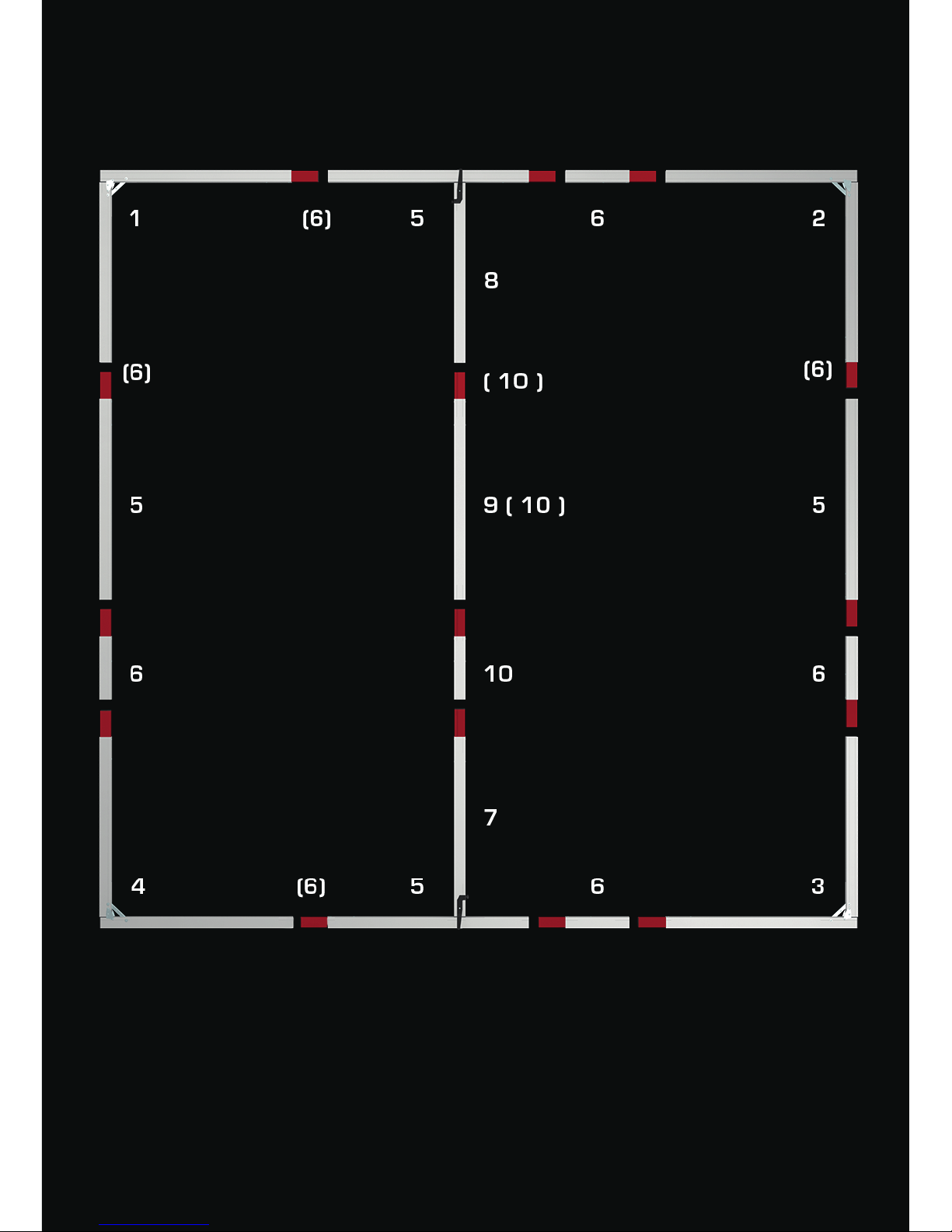
FRAME SET UP
All components of the mobile projection screen are labeled.
For assembly, start with the basic frame. Unfold the corner elements 1 to 4. Do not engage the shear
joints now and lay out the components according to their labeling. The standard elements 5 (110cm) and
supplementary frame components 6 (below 110cm) have to be inserted according to their labeling (see
sketch above). In case of two supplementary frame components 6 and (6) per frame side, the standard
elements 5 (110cm) have to be placed in between of the two supplementary frame components 6 and (6).
Engaging the shear joints ensures the maximum screen stability.
VARIOCLIP FRAME COMPONENTS
Page 6
90°
1
2
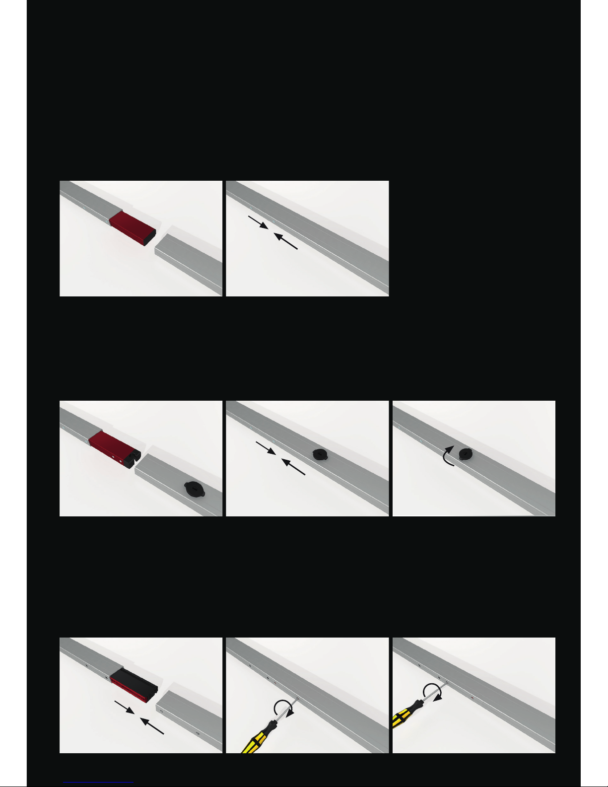
CONNECTION TYPES
Depending on the application and screen size three dierent connection types are available for VARIOCLIP.
VARIOCLIP
The quick and easy plug-in connection for small to medium sizes when installed with legs.
VARIOCLIP LOCK
The plug-in connection with additional locking for larger screens and/or “ying- screen“ mounting.
A simple 90 ° rotation and the connection is secured. No tool is required.
VARIOCLIP CLAMP
The perfect prole connection for very large projection screens ensures optimum form stability and
minimum deection. The frame sections are joined together free of play by the clamp bar with the
included Torx screwdriver.
Page 7
7
10
10
9
8
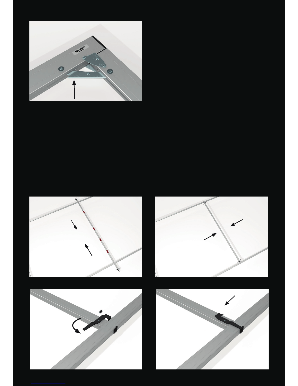
FRAME SET UP
Engaging the shear joints ensures the maximum
screen stability.
CENTRE SUPPORT AND HORIZONTAL STRUT
The center support consists of a prole „centre support bottom“ 7 and a prole „centre support top“ 8 and
according to the screen size, and additionally of parts “standard component - centre support“ 9 (110cm) and
a “supplementary component-centre support“ 10. These components are assembled so that the prole
“centre support“ 7 and 8 are placed with the clamp facing outside. Slide the centre support between top and
bottom edge of the assembled screen frame, align it centrically and secure the centre support with the wing
screws. VARIOCLIP and VARIOCLIP LOCK are supplied with one middle strut and middle leg from a width of
700cm. At very high projection screens in addition to the center supports a horizontal strut is tted. Please
follow the enclosed set up scheme.
Page 8
2
3 4
5 6
1
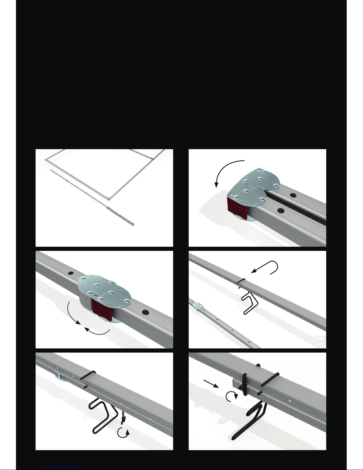
FOLDABLE LEGS FOR VERTICAL ADJUSTMENT
The legs are foldable for compact transport volume. All prole elements are connected with snap joints
or hinges inseparable.
MOUNTING
1 First open the vertical elements of the legs (with holes) 2-3 The snap joints engage automatically. 4 To
secure the legs by a single person, we recommend the use of set up supports.
Slide on with the upper round steel fork two set up supports each on the legs and center supports. Lay
on the legs on the bottom bow and align the hole pattern matching the connection points at the desired
set-up height. (Please follow the separate instructions for set up support). 5 The feet are secured with
two wing screws on the lower vertical frame element and the clamp connectors are attached at the top
of the feet 6.
Note: Please nd the instructions for telescopic support attachment under chapter SET UP
Projection screen
frame
Foldable legs
Page 9
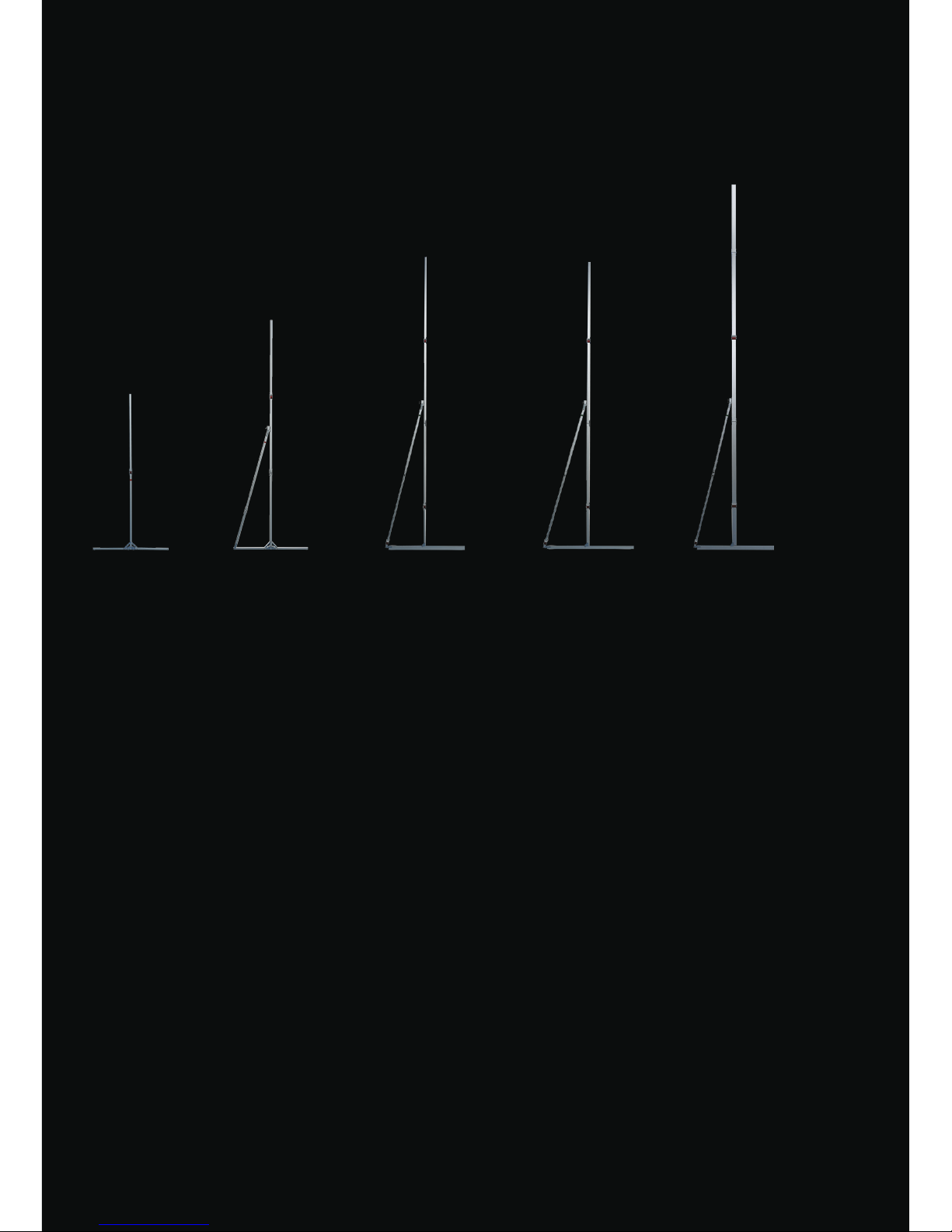
Please mind the maximum set-up height of the legs:
min: minimum height of the bottom edge of the frame
max: maximum height of the bottom edge of the frame without additional safeguarding
Set-up heights are points of reference and have to be adapted in accordance with the
screen size and ambient conditions. Set-up heights are based on absolute vertical alignment at indoors
without additional force eects (e.g.: wind, air condition draught,..)
When a high degree of stability is needed, especially with large screens or a high set-up
height, we recommend using AT 64 legs. AT-Legs have a telescopic support that is tightened with two
wing screws.
AT 32/64
430 cm
min: 9cm
max: 146cm
AT 64
550 cm
min: 9cm
max: 176cm
AT 32
320 cm
min: 6cm
max: 113cm
T 32
220 cm
min: 6cm
max: 82cm
AT 48
415 cm
min: 9cm
max: 161cm
LEG TYPES
Page 10
1
3
4
2
1
1
3
4
2
1
33 44
22
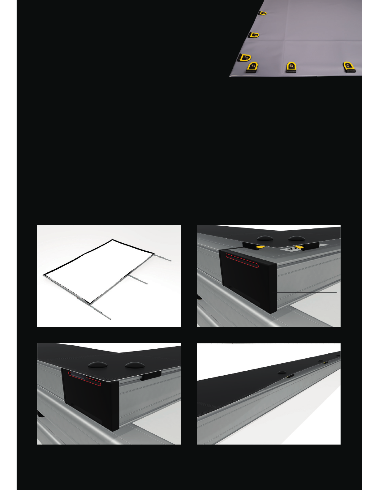
PROJECTION SURFACE
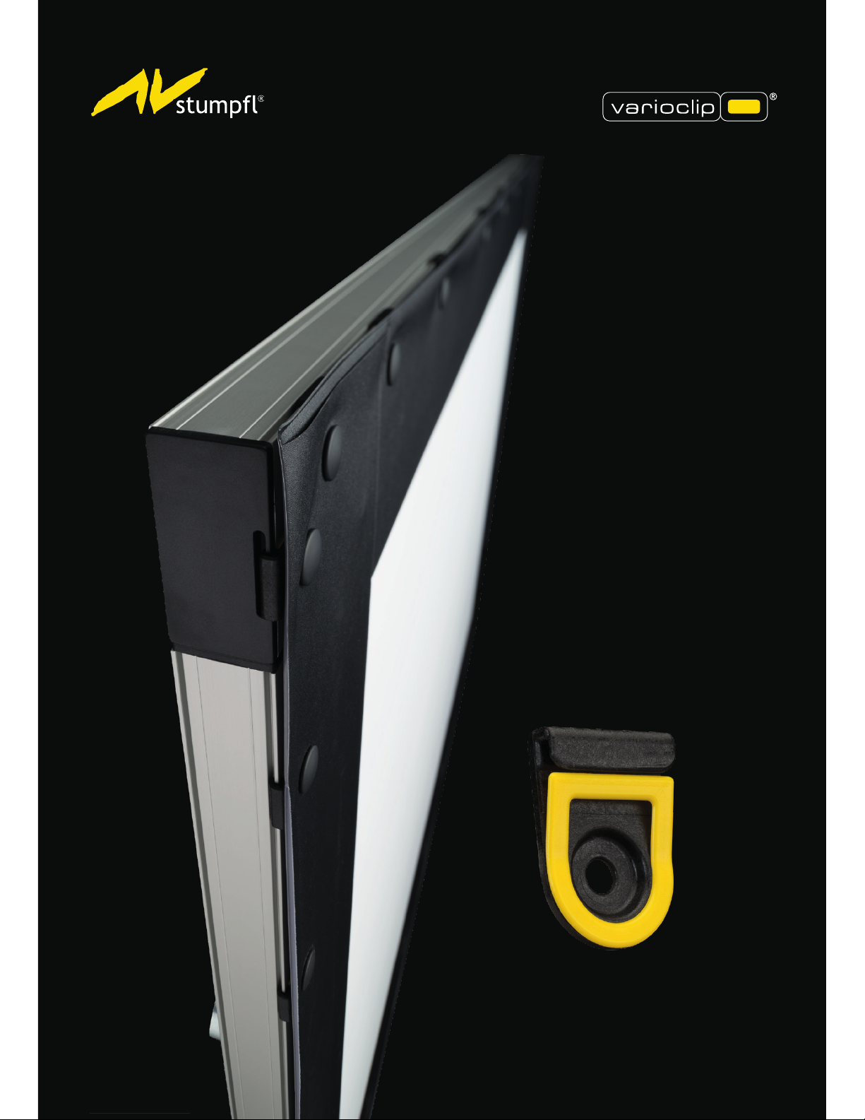
In projection system VARIOCLIP the projection surface is equipped
with the patented QUICKCLIPTM instead of snap fasteners. (see
picture right).
SURFACE MOUNTING
1 Lay out the surface on the frame with the label „OBEN-TOP“ corresponding with the upper frame bar.
2-3 Hook the rst QUICKCLIP
TM
into the slot of the corner plug and additionally a second QUICKCLIPTM
along the vertical and horizontal prole groove. Repeat this step according to the order in picture 1. 4
Finally stretch all the remaining QUICKCLIP
TM
over the prole edge. The QUICKCLIP
TM
snap into place
automatically.
! Please mind the instructions for projection surfaces in chapter GENERAL!
Corner plug
with slot
Page 11
11
33
44 55
22
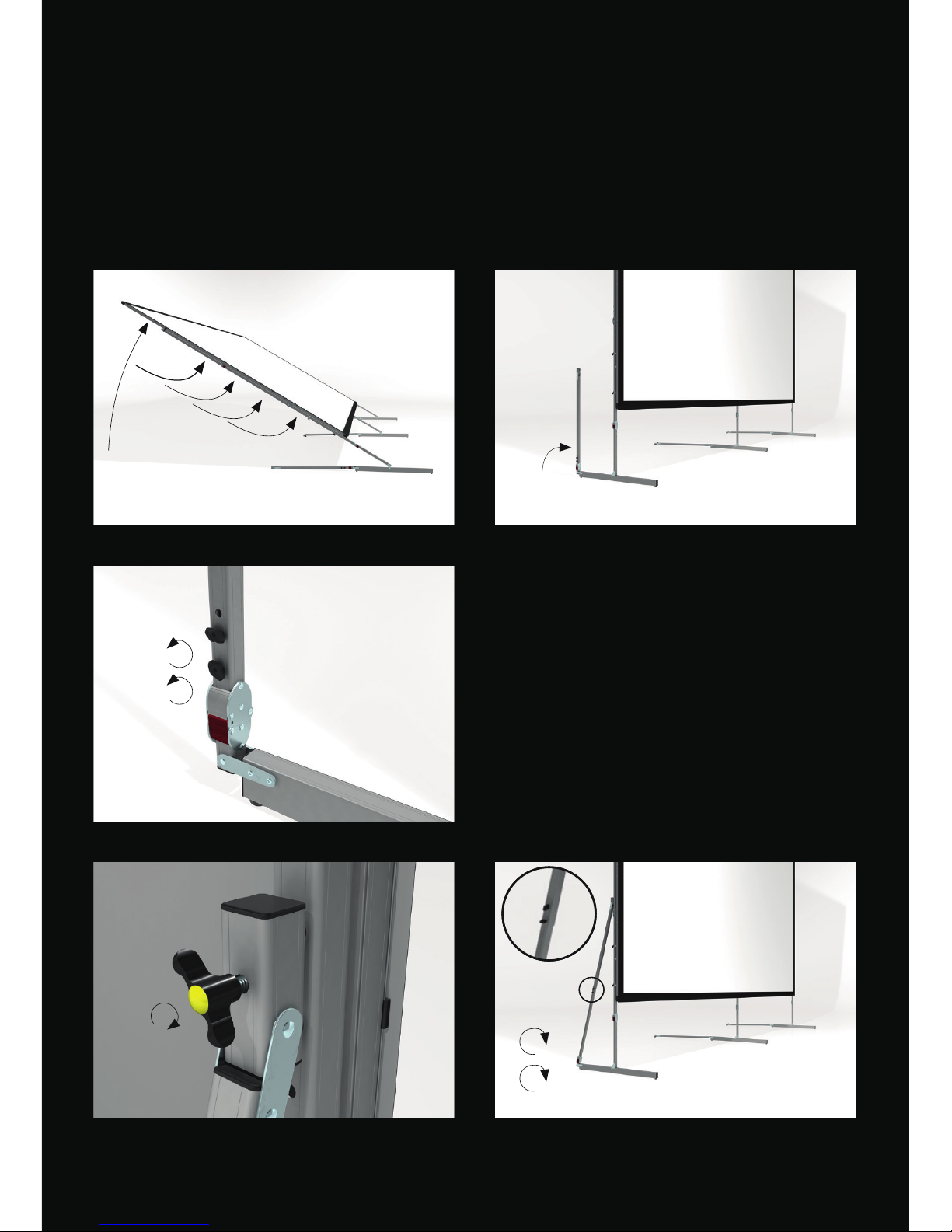
SET UP
1 Lift the projection screen with one person at each of the top corners and put it up by supporting
the screen along the vertical frame elements.
To avoid mechanical overload and damage of the screen elements and legs with large screens or high
set-up height, the screen has to be raised with an appropriate number of persons or rather by using
hoisting devices.
TELESCOPIC SUPPORT ATTACHMENT
2 Raise the telescopic support. 3 Untighten
the wing screws. 4 Bolt the telescopic support
with the wing screw M8x50mm (yellow).
5 Finally retighten the telescopic support clamp.
Page 12
1
3
2
1
1 2
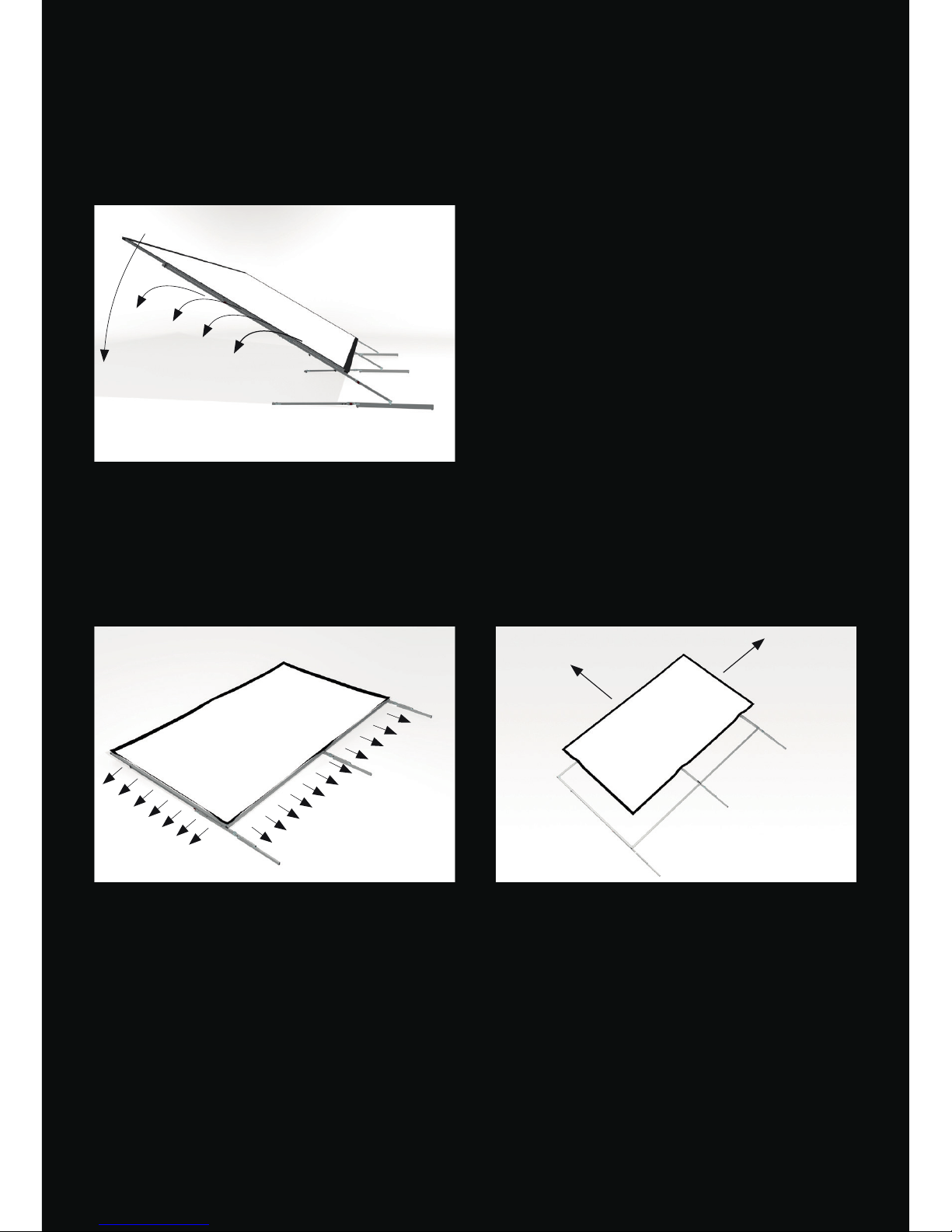
BREAK DOWN
Open the shear joints and telescopic leg supports with one person next to each of the foldable legs.
Bring down the screen by supporting the screen along the legs and vertical frame elements towards the
top corner edges.
BREAK DOWN NOTE
1 To detach the projection surface you have to remove the QUICKCLIPTM on one vertical and one
horizontal frame side only. 2 Now the surface can be pulled o the frame easily.
Page 13
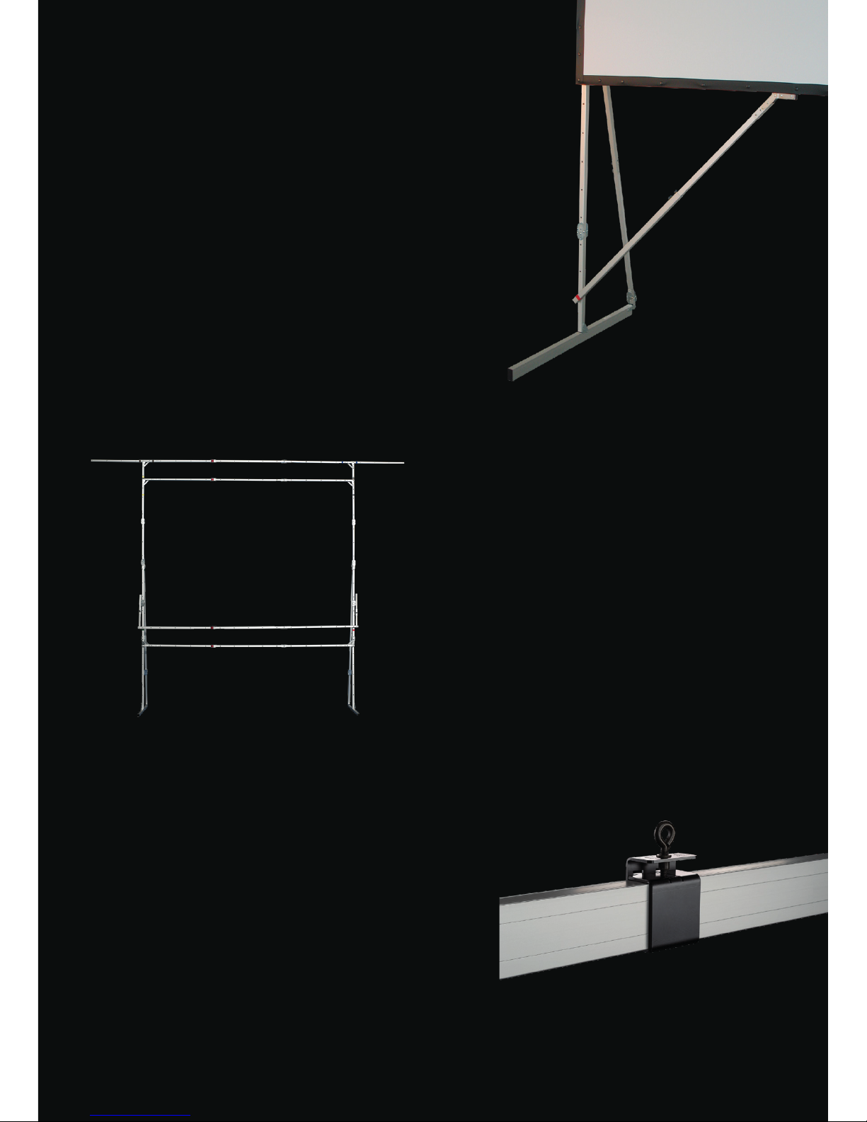
DRAPEKIT
To drape a projection screen with decoration
curtains. Depending on requirements, various
frame parts can be used to attach the drapes
Valance Bar (top drape), Wing Bar (left and right
drape) and Skirt Bar (bottom drape - height
adjustable for aspect ratio change) Heavy drapes
have to be attached after the set up to avoid
damaging of frame parts!
EASYFLY
TM
SUSPENSION CLAMP WITH EYEBOLT
This adapters for Varioclip can be attached quickly
and easily at any point. The eyebolt xes the
adapter to the prole, oering professional hanging
possibilities. Available for prole sizes 32x32mm
and 64x32mm. max. load 30 kg/60 lbs.
ANTI-SWAY BRACE
To increase the side-stability of the projection
screen the in length variable Anti-Sway Brace has
to be screwed on the leg and clamped to the basic
frame.
ACCESSORIES
Page 14
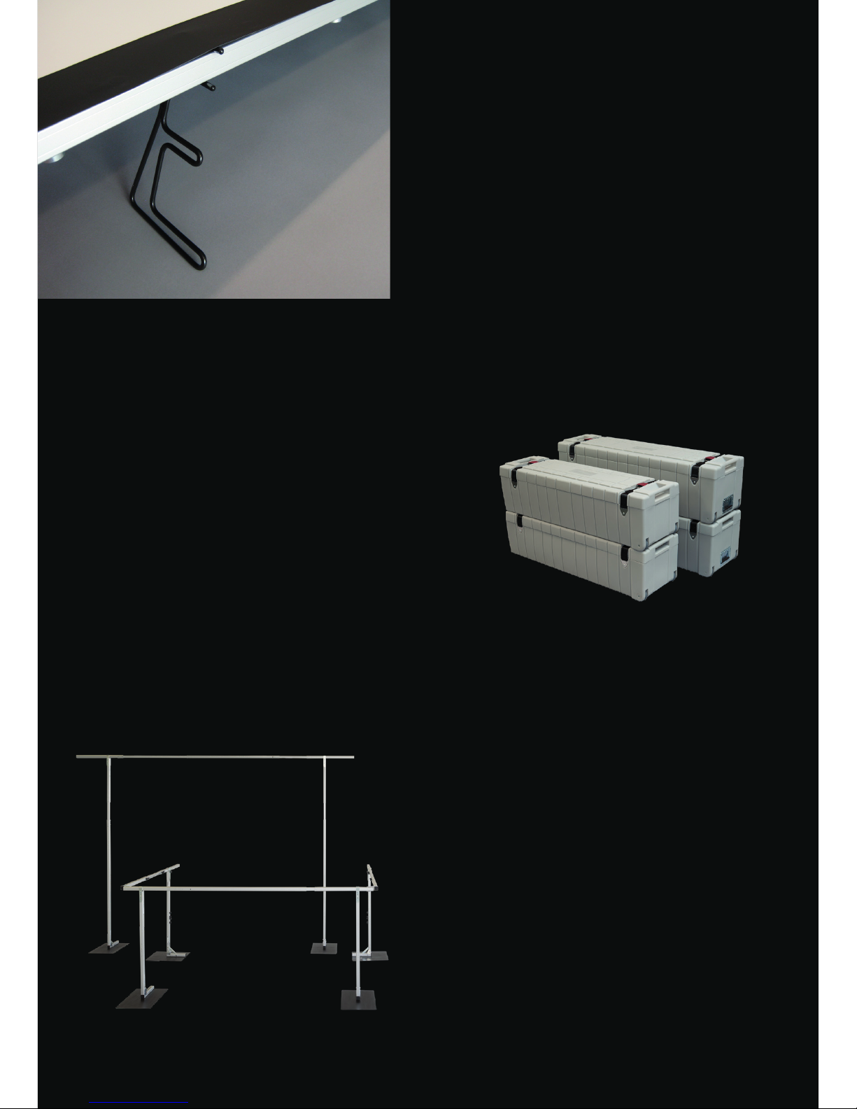
DRAPE RUNOFF
This universal and transportable Drape System
can be used as independent partition, to mark
out control areas or to allow exible room design.
A few elements combined with the telescopic
system suce to accomplish a variety of decorative
purposes – no tools required. The decoration
material is attached by Velcro fasteners.
SET UP SUPPORT
The optional available, set up support allows an
easy mounting of the legs. By means of the 4
round bar holders the wings screws can be bolted
by one person only without holding the frame and
leg in position.
FLIGHT CASE
As an option we oer sturdy, stackable transport
cases with rollers for all mobile projection screens.
Transport case small: size 123 x 38 cm, height 34 cm
Transport case large: size 134 x 38 cm, height 37 cm
 Loading...