

Page 1
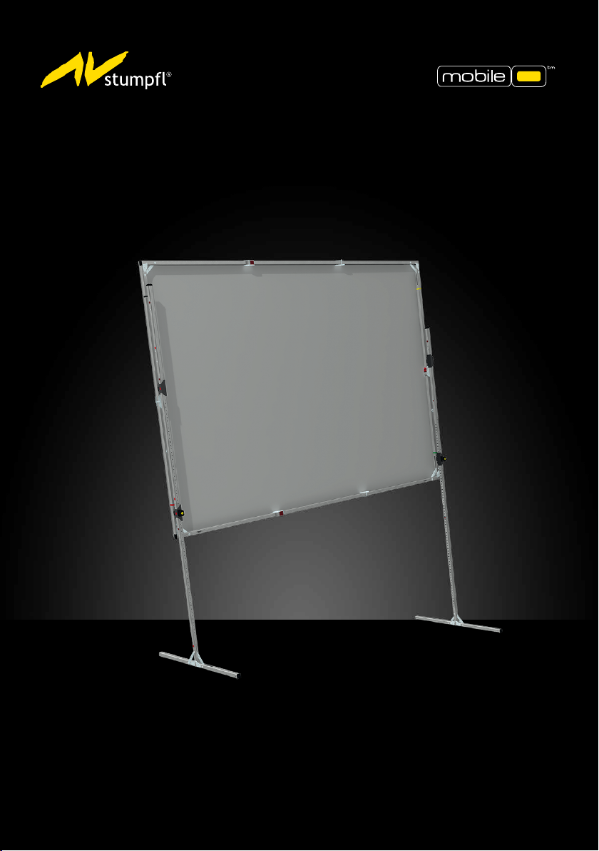
26CT
T32-SHIFT
INSTRUCTION FOR MOBILE PROJECTION SCREENS
Page 2
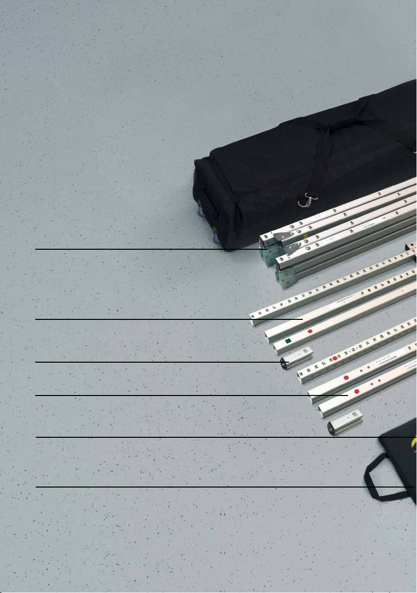
MONOBLOX 32
MONOCLIP 32
Compact transport volume
due to patented snap joint technology
Special extruded and hardened aluminum alloy
allows maximum stability at minimum weight.
T32-SHIFT EXTENSION
110 cm
T32-SHIFT ENDMODULE
T32-SHIFT EXTENSION
55 cm
FRAME ADAPTER
Frame adapter und transport lock in yellow bag.
PROJECTION SCREEN BAG
Lined storage bag for projection screen
2
Page 3
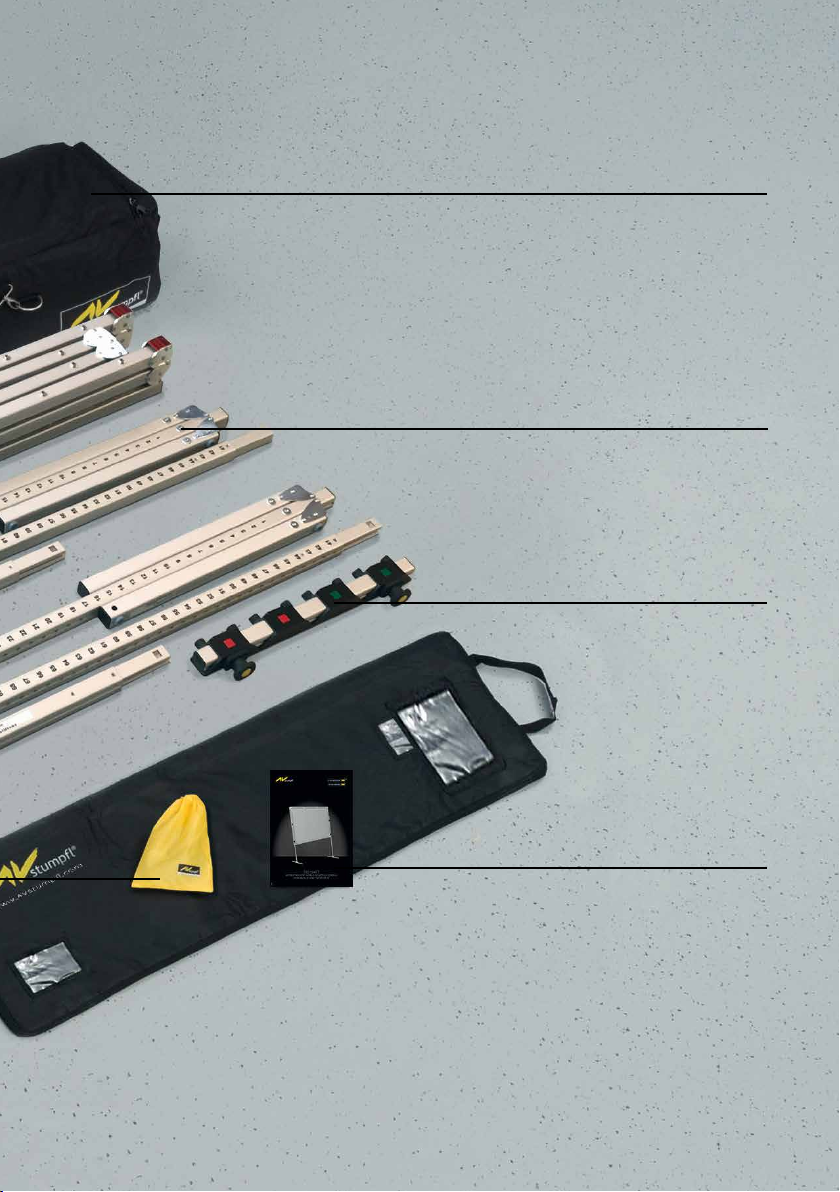
SOFTBAG WITH WHEELS
padded , tearproof nylonbag
with wheels and carrying straps
small 128x25x30 cm
big 133x31x35 cm
T32-SHIFT BASIC MODULE
116 cm
LOCKING- AND
SLIDING MODULE
on transport prole
ASSEMBLY INSTRUCTION
3
Page 4

INDEX
GENERAL 5
STANDARDS, REGULATIONS
AND TECHNICAL SPECIFICATION 5
SAFETY 5-8
OPERATION, MAINTENANCE and SERVICE 8
WARRANTY 9
LEG VARIANTS 10
ADAPTION 11
ADAPTERS 12
ATTACHING THE T32-SHIFT LEG 13-14
EXTENSION PARTS 15
HEIGHT ADJUSTMENT 16
DISASSAMBLY 17
TRANSPORT LOCK BOLTS 17
SUBSEQUENT VARIO FRAME MODIFICATION 18
4
Page 5
GENERAL
WARNING
T32-SHIFT
The T32-SHIFT leg makes it possible for JUST ONE person to easily adjust a mobile projection screen‘s
height, without having to disassemble it rst.
The T32-SHIFT can be combined with all existing AV Stump screen systems.
STANDARDS, REGULATIONS and TECHNICAL
SPECIFICATION
This projection screen is in accordance with the safety regulations in DIN standard 19045 and
DIN 56950. The screen fabric is comply with DIN 4102 part 1 and the specications of the according
data sheet. For the technical details and projection-specic material parameters please refer to the
corresponding product data sheet: www.AVstump.com/projectionmaterials
Detailed data of frame components, legs and projection surface can be found on the type labels on
each component and on the labeled soft bags, roller bags or ight cases.
SAFETY
GENERAL INFORMATION FOR THE MANUAL AND SAFETY
This operating manual forms part of the projection screen system and enables a safe and ecient
operation. The safety section provides information about important safety aspects for the protection
of persons, frame and projection materials. Task-related warnings/notes are also contained in the
individual chapters. Read instructions through completely before proceeding and keep for future
reference. You can nd manuals electronically on our website: www.AVstump.com/downloads
PACKAGING MATERIAL
Danger of suocation!
• Keep packaging material and foils away from children.
• Do not let children play with packaging material.
Unpack without cutter or any other sharp tool to avoid damaging of
the projection screen. Remove packaging materials by hand. Unpack
projection surface after assembling of the frame.
5
Page 6
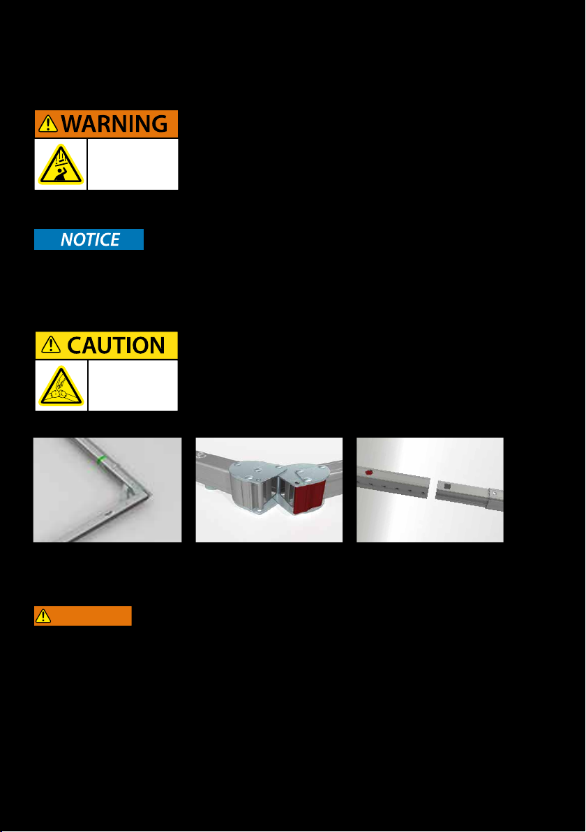
SET UP-ASSEMBLY
WARNING
MECHANICAL HAZARDS
Danger of injury due to improper assembly.
Make sure all frame parts assembled correctly and all hinges
and joints are locked before raising screen to standing
Projection surface damage in case of faulty assembly or set up.
Make sure all frame parts assembled correctly and all hinges and joints are locked before one unfold and
attach the projection surface.
Please be careful
not to pinch
your ngers!
position. Falling parts can cause severe injury or death!
FRAME AND LEG COMPONENTS
Foldable snap joints, corner hinges and plug-in connections can
lead to injury to the hands (body parts). Please be careful not to
pinch your ngers!
FALLING OVER
Falling over of a projection screen can cause severe injury or death!
To avoid falling over:
• Make sure that the projection screen is in level.
• Mind the maximum set-up height of the legs - Please follow the instructions in chapter LEG VARIANTS (site 10)
• Prevent air draft
• Use additional weights on the base prole of the leg to gain higher stability.
• Use suspension points (e.g.: EasyFly) according to the overall system weight for additional safeguarding.
Do not put additional load on the screen frame!
Do not use outdoors!
6
Page 7
WARNING
Mobile projection screens are developed for indoor use only.
Failure to follow warning may result in personal injury due to unforeseen acts of nature.
Any damage and consequential damage caused by outdoor use is not covered by warranty.
BASIC SAFETY REQUIREMENTS
Basic safety requirements for „ying“ projection screens and wall- or ceiling mounting!
If persons are able to stand under the loads, fastening points and slings must not be loaded more than
half the value of the load bearing capacity stated by the manufacturer.
When planning the event or production, not only dead loads but also dynamic forces, potential
breakdown loads and additional loads during operation, as well as during assembly and dismantling
must be taken into account.
Observe the local safety regulations!
FLYING SCREEN
If a modular projection screen is used as a “ying” (free hanging) screen, then all plug-in and clamp
connections must be secured against becoming loose and falling.
It is not allowed to use the projection surface holding the frame parts in position!
Falling parts can cause severe injury or death!
Please make sure that all components are secured safely before raising screen to standing position and
lifting. Use the necessary number of suspension points (e.g.: EasyFly) according to the overall system
weight. A second/auxiliary safeguarding system is mandatory (e.g. steel rope catch)
Please follow the detailed instruction in the manual.
It is not allowed to use the projection surface holding the frame
parts in position! Falling projection screens or parts can cause
severe injury or death!
WALL- or CEILING MOUNTING
Before mounting, make sure that the wall or ceiling, as well as the xing points meet the safety
requirements of the local standards and the required load can be beared.
Danger of injury
due to improper
disassembly.
Falling parts can
cause severe injury
or death!
Please be careful
not to pinch
your ngers!
Beware of
pinch points.
7
Page 8
DISASSEMBLY
For disassembly the same safety instructions apply as for assembly and set up. Bring down a projection
screen with the appropriate number of people to avoid falling over of the screen.
Falling parts can cause severe injury or death!
OPERATION, MAINTENANCE and SERVICE
FRAME ELEMENTS, LEGS and ACCESSORIES:
The frame elements, legs and additional elements are maintenance-free.
PROJECTION SURFACE:
The projection surface is packed into a separate lined soft bag to avoid any damage by the frame parts,
bleaching and discoloration.
Additionally, following instructions have to be adhered to:
Do not allow the projection surface to get in contact with sharp objects.
Do not bring printed and coloring objects (instructions, magazines, etc.) in contact with the
projection surface!
Do not write on the projection surface!
Colors penetrate the projection surface and cannot be cleaned anymore!
Store the projection surface cleaned and dry at room temperature only!
The projection surface has to be folded with the front layer inside; in order to avoid soiling and damage.
When folding the projection surface insert the enclosed foamed plastic foil between snap buttons and
surface to avoid permanent marks.
COLD BREAK
A projection foil must never be stored or transported below 5° C. There is a risk of a cold break! The
lm becomes very brittle and splinters like glass! When transporting the projection surface at low
temperatures do not unfold the surface unless it has reached its full elasticity at room temperature.
Otherwise there is the risk of cold break of the projection screen.
The ideal temperature range for assembling folding screens to prevent damaging the surface is 54°-82° F
(12°-28° C). Assembling below recommended temperatures may damage surface and void warranty
CLEANING OF THE PROJECTION SURFACE
Use a white clean cotton cloth saturated with clear water (optionally mild soap water) and gently
wipe the area in one direction (no circular motion). Wipe dry with another cotton cloth.
To clean a stubborn stain, use methylated spirit and follow the same procedure.
Clean rear projection surfaces in case of imperative only!
8
Page 9

WARRANTY
The warranty period for production deciencies is 5 years for the frame elements and 24 months
for the projection surface.
Mobile projection screens are developed for indoor use only.
Any damage and consequential damage caused by outdoor use is not covered by warranty.
The general terms and conditions are available at http://avstump.com/agb
LIMITATION OF LIABILITY
All the details in this manual were compiled in consideration of the standards and legal regulations
applicable at this time, as well as the experience of the manufacturer and qualied sta. The
manufacturer accepts no liability for damage to persons or things (projection screen, other devices,
goods, etc.) resulting from:
Non-observance of the manual and the regulations/safety instructions contained therein.
• Failure to comply with the local safety regulations.
• Inappropriate use (misuse).
• Use of unauthorized and non-trained sta.
• Unauthorized equipment conversions and technical modications by the operator himself.
• Use of spare parts not approved by the manufacturer.
• Typesetting and print errors.
Failure to observe the above points will invalidate the warranty claims.
Technical specications are subject to change without notice.
The local regulations and safety regulations and the essential safety requirements apply for the use of
this projection screen.
DISPOSAL
At the end of its lifetime this product must not be disposed of with normal household waste but needs
to be taken to a collection site for recycling.
Separate disposal of the product makes an important contribution towards environmental protection.
Frame components and legs are made of aluminum and steel.
The projection material is PVC vinyl.
Contact your local disposal company for the address of a collection center.
Subject to modications, errors expected !
9
Page 10
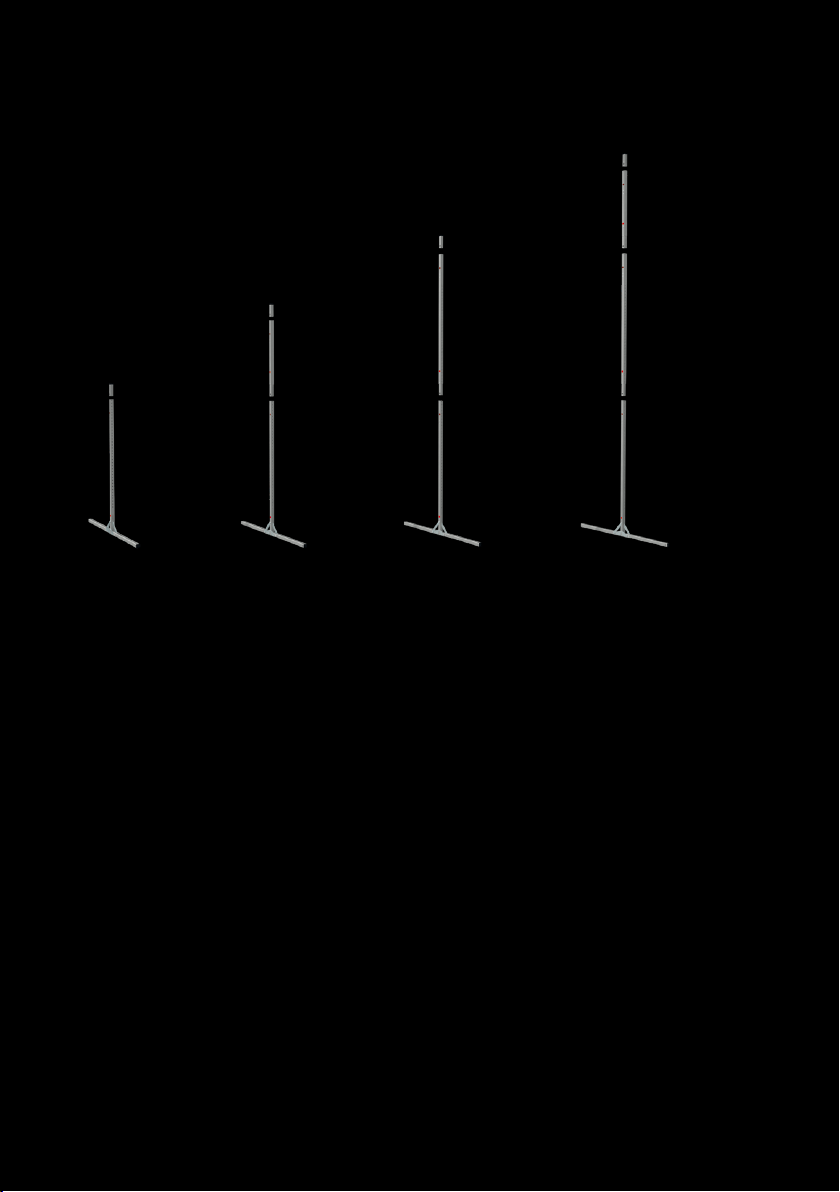
LEG VARIANTS
end module
extension
55cm
end module
end module
extension
22“ (55cm)
end module
basic module basic module basic module basic module
46“ (118cm)
min: 2“ (5cm)
max: 28“ (70cm)
T32-SHIFT legs can be assembled in four dierent lengths. According to the screen frame height and the
desired set-up height the leg can be assembled with the following lengths: 46“ (118cm), 68“ (173cm),
90“ (228cm) and 111“ (283cm).
Compatible with all mobile AV Stump screen systems.
Please mind the maximum set-up height of the leg:
min: minimum height of the bottom edge of the frame
max: maximum height of the bottom edge of the frame without additional safeguarding
68“ (173cm)
min: 2“ (5cm)
max: 49“ (125 cm)
min: 2“ (5cm)
max: 49“ (125 cm)
extension
43“ (110cm)
90“ (228cm)
extension
43“ (110cm)
111“ (283 cm)
min: 2“ (5cm)
max: 49“ (125 cm)
Set-up heights are points of reference and have to be adapted in accordance with the
screen size and ambient conditions. Set-up heights are based on absolute vertical alignment at indoors
without additional force eects (e.g.: wind, air condition draught,..)
10
Page 11
1 2
3
ADAPTION AND
ASSEMBLY
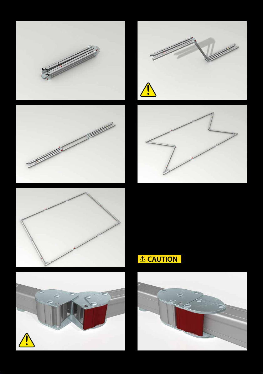
To prepare your mobile projection screen for
use with the T32-SHIFT legs, you have to attach
adapters to the backside of the frame – once
only. 1-7 Unfold the screen frame with the
backside facing upwards. Open the folded frame
horizontally 1-3 and then vertically 4-5. The
locking hinges engage and lock automatically 6-7.
5
6
Beware of pinch points!
4
7
11
Page 12
1
2
3
ADAPTERS
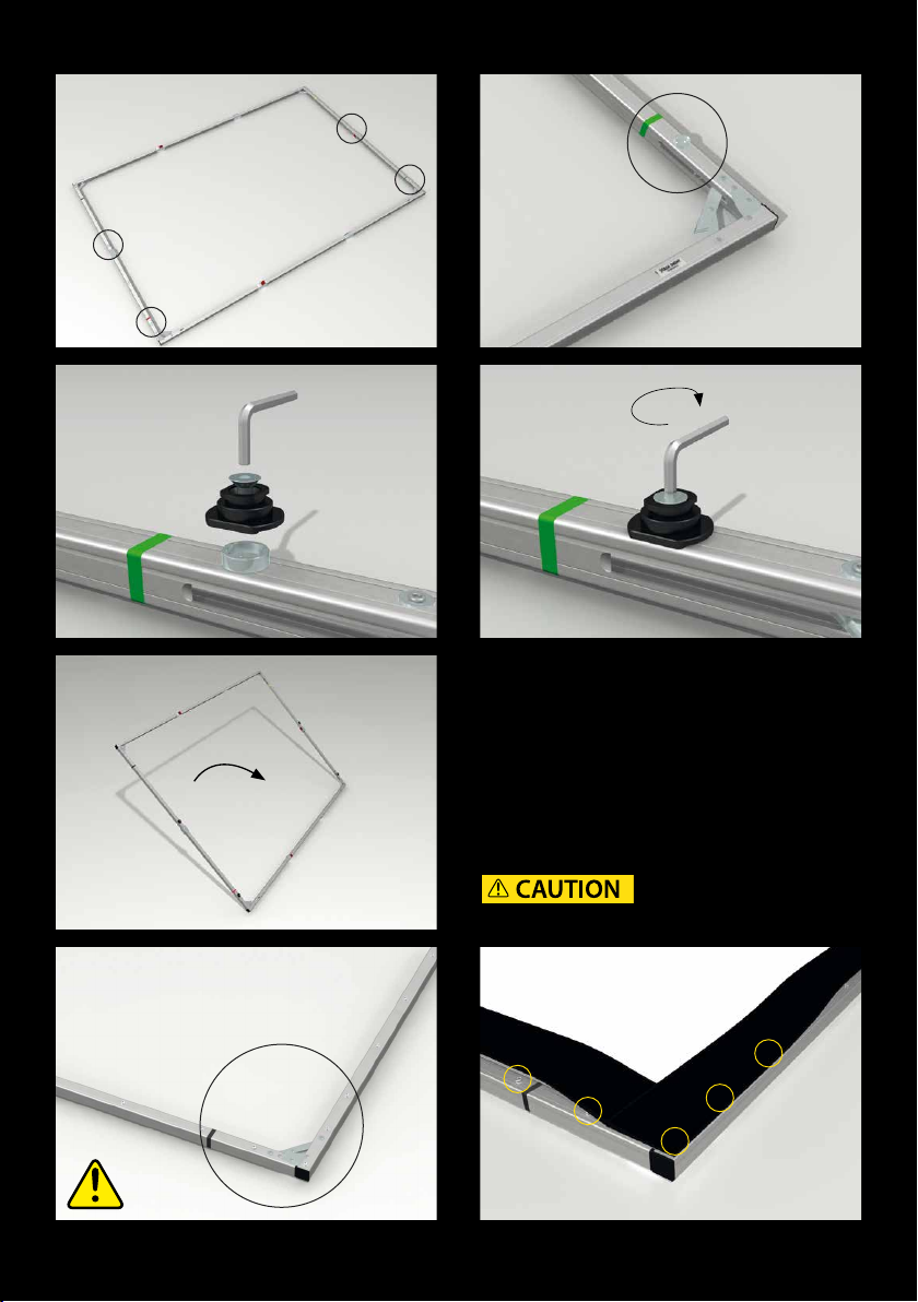
1-4 Attach the frame adapters to the round
„spacers“ on the backside of the screen, with
the enclosed countersunk screws, using the
hexagonal spanner.
5-7 Flip the frame and attach the projection
surface.
Beware of pinch points!
5
6
4
7
12
Page 13
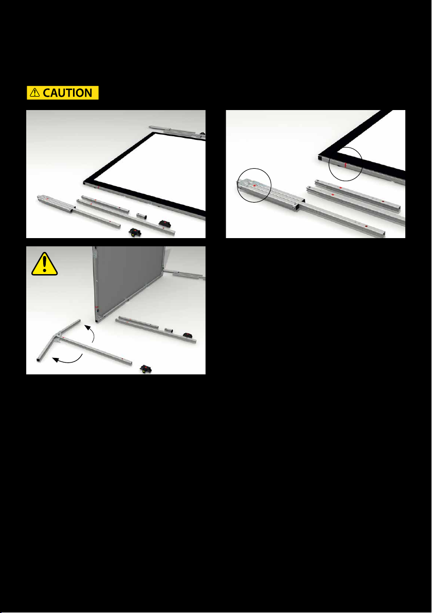
ATTACHING THE T32-SHIFT LEGS:
1-2 Lay out the leg components next to each bottom corner of the frame. Each component is labeled
either with a red or green square, which indicates the corresponding side of the frame.
3 Start with the base module. Open and secure the base bars.
Beware of pinch points!
1 2
3
13
Page 14
4
5
6
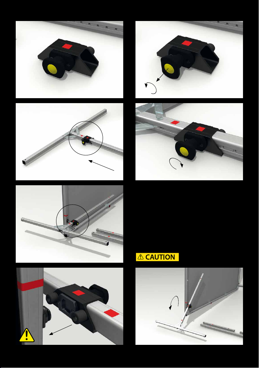
4-5 Loosen the locking mechanism. Just pull the
button and turn it counterclockwise.
6-7 Next, slide the locking-module onto the
lowest point of the base module. Make sure that
the colored squares match.
8-9 Lift the base module and place the locking
module onto the frame adapter in a horizontal
position.
10 Secure the bayonet coupling by turning the
base module in a vertical position.
5
8
Beware of pinch points!
9
7
10
14
Page 15
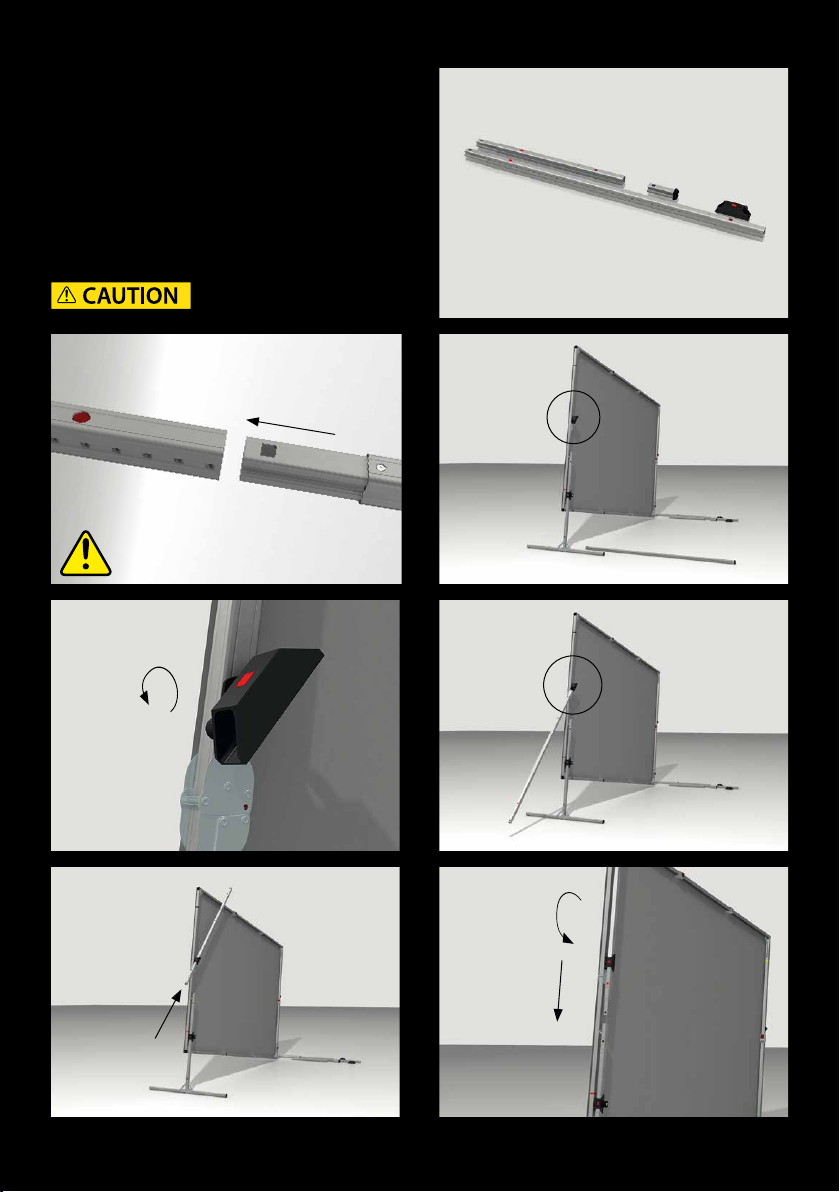
EXTENSION PARTS
1-2 Next, start to assemble the extension parts
and the end module. Just plug together the
components so that the colored labels are
on the same side. The snap-lock will engage
automatically. 3-6 Attach the sliding module in
a slightly o axis angle. Check that the colored
labels are matching and slide in the extension
parts. 7 Turn the extension parts vertically and
connect them with the base module.
Beware of pinch points!
1
2
4
6
3
5
7
15
Page 16
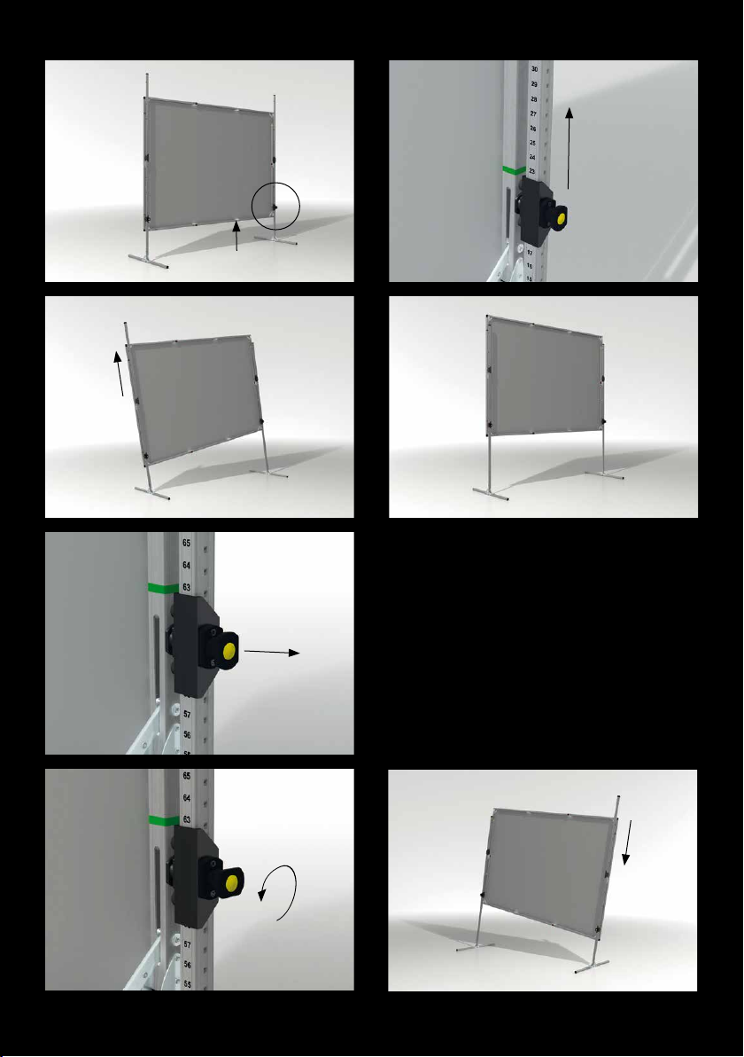
1
2
3
HEIGHT ADJUSTMENT
1-7 To adjust the screen height, one can start
at the bottom of the scale and simply move the
screen up to the preferred position.
The T32-SHIFT will lock automatically.
The height can be adjusted in one-inch steps
(2,54cm). No extra measuring is needed to
ensure the frame is level, due to clearly marked
height scales.
5
6
4
7
16
Page 17
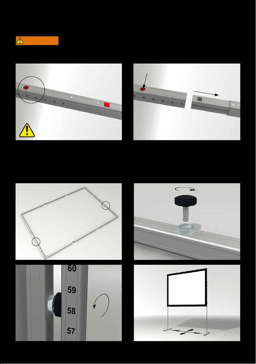
DISASSAMBLY
WARNING
Danger of injury due to improper disassembly. Falling parts can cause
severe injury or death!
1-2 The snap lock is released by the red button. The proles then can be separated.
1 2
TRANSPORT LOCK BOLTS
1-4 To allow a single person to lift and move the screen, optional transport lock bolts can be attached.
For that turn the transport lock bolt against the T32-SHIFT leg.
1 2
3 4
17
Page 18
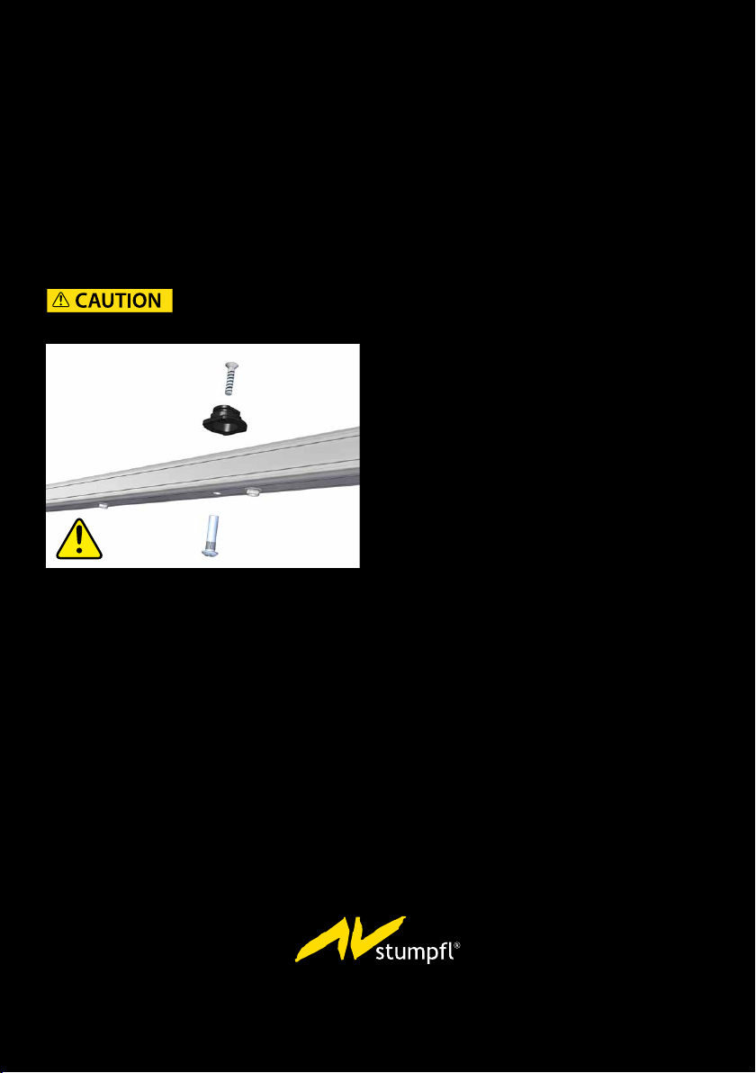
SUBSEQUENT VARIO FRAME MODIFICATION
BVZ-MOD/HM/SHIFT
screen modicaon VARIO, sleeve nut M6 + countersunk screw M6x30mm
All VARIO screens that are already in use can easily be adapted subsequently on site for use with
SHIFT legs. All one must do is to drill a hole and bolt an adapter onto the plug-in proles. Detailed
instructions can be found in the related manual.
Optionally we oer a factory-based service of a subsequent attachment of additional insert nuts with
spacers to mount frame adapters for SHIFT legs.
Beware of pinch points!
(picture VARIO 32)
18
AV Stump GmbH | Mitterweg 46 | 4702 Wallern
AVstump@AVstump.com | www.AVstump.com | +43 7249 42811
 Loading...