

Page 1
INLINE
MANUAL FOR ROLL UP SCREENS
08/17
Page 2

DIRECTORY
GENERAL INFORMATION 3
SAFETY INSTRUCTIONS 4
METHODS OF INSTALLATION
QuickMount-Brackets 7
Mounting Plate 10
Universal-Mounting Brackets 11
Wall/Ceiling Brackets 12
Wall Brackets 13
Ceiling Brackets 14
CEILING CASE for ceiling integration 15
CEILING CASE with mounting set 15
Projection screen for ceiling Integration 19
Mounting set for suspended ceiling 19
ELECTRICAL INSTALLATION 22
STOP POSITION ADJUSTMENT
Motor left/ fabric back and motor right/fabric front 23
Motor left/ fabric front and motor right/fabric back 24
ACCESSORIES 25
MANUAL ROLL-UP SCREENS
Crank mechanism 27
Spring-Roller mechanism with soft-rewind 27
TENSIONING UNIT 28
Page 3

3
ROLL-UP PROJECTION SCREEN INLINE
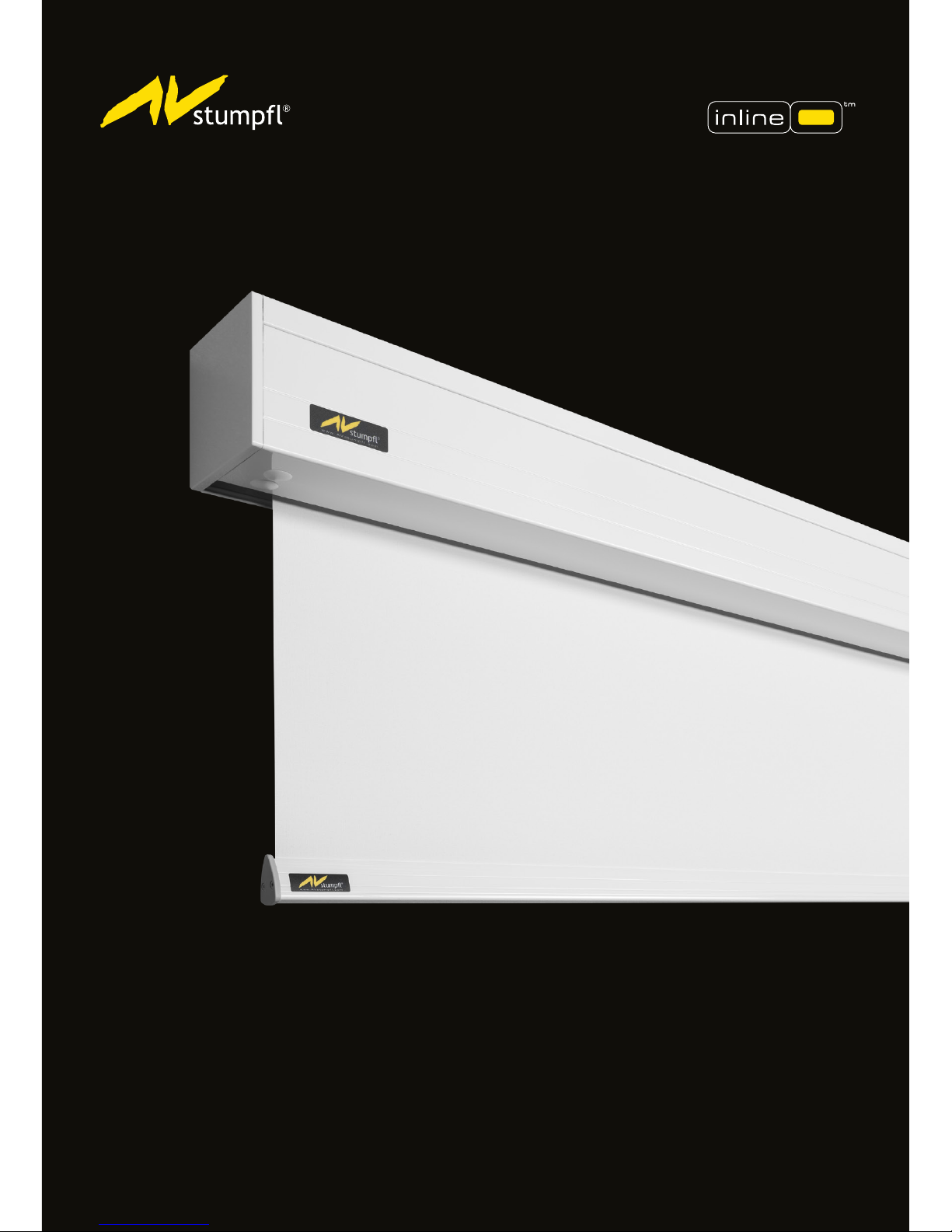
Roll-up screen INLINE is a permanently installed projection screen consisting of a roll-up tube that
is attached to a drive system (asynchronous tube motor) on one side and pivoted on the opposite.
The drive and the bearing are mounted on lateral metal plates, which are mechanically connected
to a two-part screen casing made of aluminum sheet (protective casing). The projection material is
rolled up on the winding tube and has a weighting prole (bottom bar) at its lower end.
The winding tube maintains the height and the projection material is unrolled downwards.
Projection screen INLINE is used for displaying images, videos, lms, etc. supplied by a projector.
INLINE projection screens can be mounted to the ceiling or to the wall via a mounting bracket and
installed in a suspended ceiling.
Detail information on the roll-up screen and the serial number VAT can be found on the type plate
on the back of the screen material in the bottom left corner and at the top of the protective casing.
QUALITY AND SAFETY
The roll-up projection screen is in line with the applicable European guidelines and standards
(incomplete excerpt):
Directive 2006/42/EG-on Machinery
Directive 2006/42/EC on Machinery
Low Voltage Directive 2014/35/EU
Electromagnetic Compatibility Directive 2014/30/EU
DIN 19045-2 Projection of still pictures and motion pictures - Part 2: Screens
DIN 56950-4 Entertainment Technology - Machinery Installations - Part 4: Safety requirements for
serially manufactured projection screens
DIN EN 60335-1 and 2 Household and similar electrical appliances - Safety - Part 1: General
requirements and Part 2: Special requirements
The screen material corresponds to a building material class in accordance with DIN 4102-1 and is
in line with the limit values for waviness according to ÖNORM A 2115.
For the technical details and projection-specic material parameters please refer to the
corresponding product data sheet. www.AVstump.com/projectionmaterials
WARRANTY:
The roll up screen INLINE may only be used as a projection screen.
No persons are allowed to stay in the operation area.
For all damages to persons and property which occur from inappropriate use the warranty will be
invalid and the manufacturer cannot be held responsible.
The intended use also includes the observance of all instructions and information contained in this
operating manual.
The warranty period for production deciencies is 24 months. Please mind the guarantee
regulations with media control panel operation on page 22.
The general terms and conditions are available at www.AVstump.com.
http://avstump.com/agb
GENERAL
Page 4
4
SAFETY INSTRUCTIONS
Before assembly check the roll-up screen for transport damage! Information on how to proceed in
cases of transport damage is provided on the info sheet IMPORTANT INFORMATION.
Before assembly make sure that the wall or the ceiling is able to carry the load. Choose the screws/
attachment material in accordance with the weight of the projection screen and the condition of wall
or ceiling.
In order to ensure optimal atness of the projection surface avoid assembly within the vicinity of
radiators, ventilation and air condition systems. To ensure safe and trouble-free operation make sure
that the roll-up screen is installed in an absolutely horizontal and torsion-free position!
ELECTRICAL INSTALLATION
The roll-up screen must be secured during transport and assembly
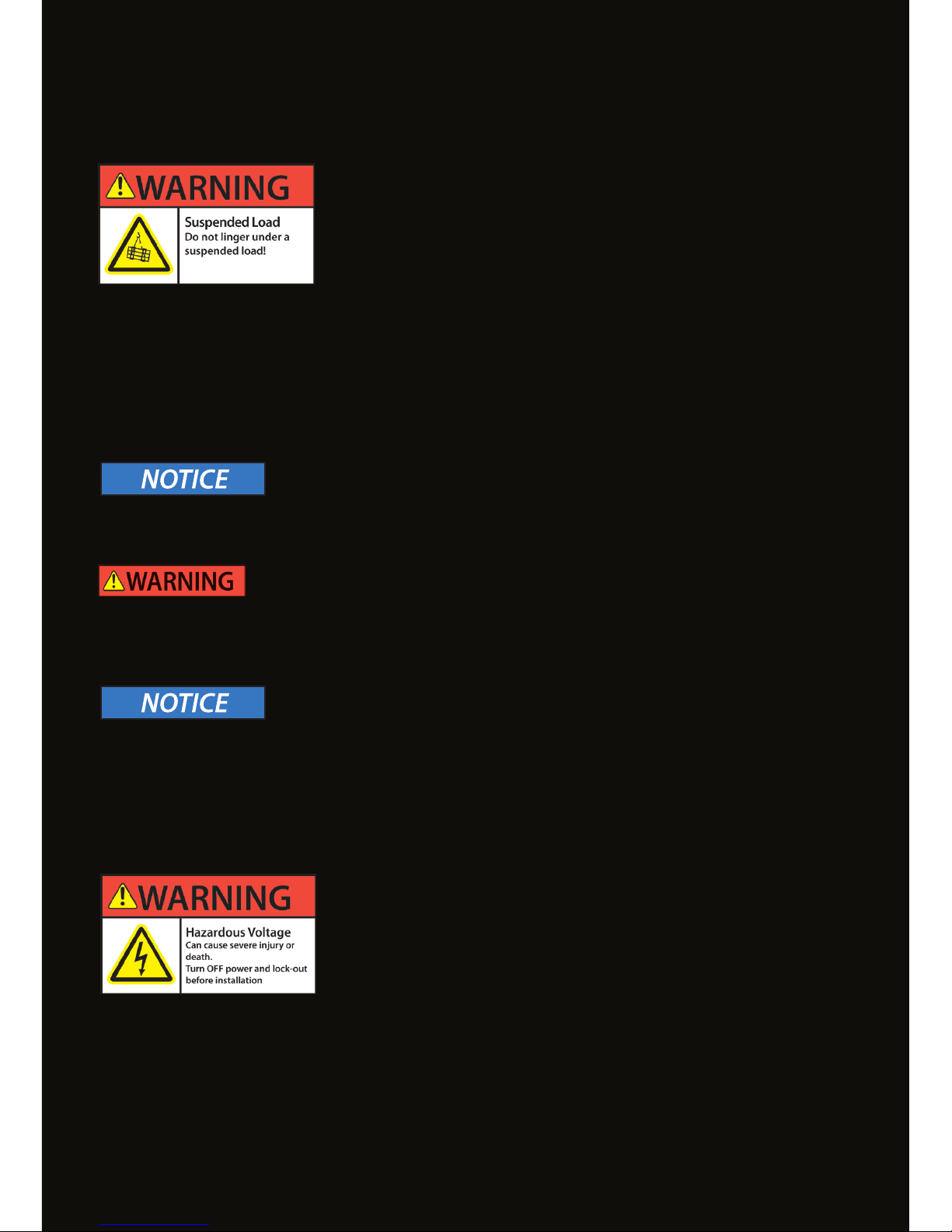
in accordance with the total weight. During lifting work, no person
must remain in the danger zone below the suspended load (roll-up
screen)! The load must be distributed evenly and secured against
falling!
The total weight is displayed on the roll-up screen type plate or on the packaging. Always use a
suciently high number of people in line with the total weight for transporting the roll-up screen.
Make sure the roll-up screen is transported and assembled horizontally and torsion-free to prevent
the safety brake from engaging.
MECHANICAL MOUNTING:
TRANSPORT - MOUNTING
The electrical installation is to be performed by a trained electrician
from a licensed expert company only. Please hand over this manual
and the connection directions that are supplied separately with
every motor or switch or control unit to the executing expert.
The electrical installation may only be carried out in a voltage-free state!
Secure the system against unintentional reconnection! Make sure that all connection cables to be
installed are de-energized and secure the unit against unintentional activation.
Prior to the installation check the isolation of the connecting cable and the cable feedthrough at the
casing for damage. Check that there is no ohmic continuity between the connecting cable and the
roll-up screen casing so that any danger by indirect contact is excluded. Control units must not be
installed in the operating area of the roll-up screen.
Page 5
5
FIRST-TIME OPERATION
When starting the roll-up screen for the rst time secure the immediate area of the screen and its
movement range. During rst-time operation the screen should be moved in steps only. When there
are signs of danger or danger situations roll-up screen operation must be stopped immediately.
During the test run the operator must always have full and direct sight of the roll-up screen.
Remove the transport protection (protective lm) and make sure that the bottom bar did not get
stuck in the roll-up screen casing during transport or assembly and that the screen material can
unwind without any problems!
OPERATION
The projection screen must only be operated in a well lit environment so as to recognize any danger
situations that might occur. During operation the operator must always have full and direct sight of
the roll-up screen so as to be able to stop it immediately when a danger situation occurs.
Supervision by adults is required when putting the roll-up screen into operation.
During operation the movement range and the immediate area of the roll-up screen must be
secured. No persons are allowed below the roll-up screen!
Before winding up the screen check the bottom bar and the screen material for damage and remove
any possible obstacles within the movement range. No additional loads must be attached to / or
lifted by the bottom bar.
In the case of recognizable damage to the roll-up screen it must immediately be taken out of service.
It can only be put back into service after being repaired and checked/cleared for use by an expert.
MAINTENANCE TIPS - CLEANING
During work at the roll-up screen make sure that it cannot be started accidentally.
Protect the screen material from soiling. If necessary clean it with a slightly damp and soft cloth.
Do not use any aggressive cleaning agents, such as acetone, turpentine, cellulose thinners or ethyl
alcohol or similar substances.
Page 6
6
MAINTENANCE
Drives, bearings and other rotating parts of the roll-up screen are permanently lubricated and are
maintenance-free. The roll-up screen must be protected from soiling.
Maintenance and repair work must only be carried out be authorized experts.
SAFETY INSPECTION
INLINE roll-up screens must undergo annual visual inspection and control run.
An annual safety inspection is not mandatory
In case of visible damage or unusual noises during the operation the roll-up screen must
immediately be taken out of service. It must only be returned to service upon successful repair
and inspection/clearance for use by an expert.
DISASSEMBLY
For disassembly the same safety instructions apply as listed for TRANSPORT - ASSEMBLY on page 4.
DISPOSAL
At the end of its lifetime this product must not be disposed of with normal household waste but
needs to be taken to a collection site for recycling.
Disassembly of a INLINE roll-up screen takes a few steps only and by separate disposal of the waste
you can make an important contribution towards environmental protection.
In separated form the materials can be recycled.
Casing components and bottom bar are made of aluminum and the lateral bracktes are made of
steel.
For the projection screen material refer to the type plate.
The motor drive is to be disposed of at a collection center for electric devices.
Contact your local disposal company for the address of a collection center.
Page 7
7
QUICKMOUNT-BRACKETS
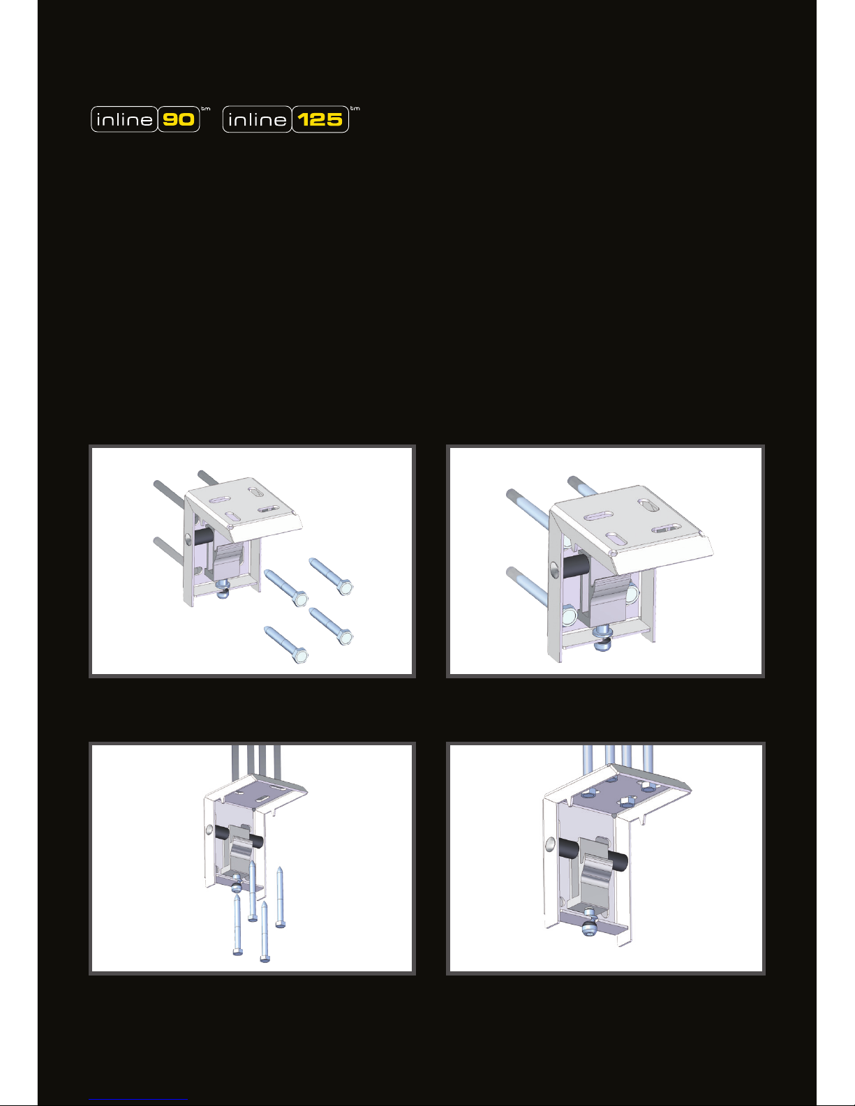
CEILING MOUNTED:
INLINE 090 and INLINE 125 come with
QuickMount brackets, as a standard.
The two QuickMount brackets can be attached
either to the wall or to the ceiling.
Use four screws which are appropriate to the
weight of the screen and the quality of the
wall.
WALL MOUNTED
Page 8
8
SYSTEM COMPONENTS
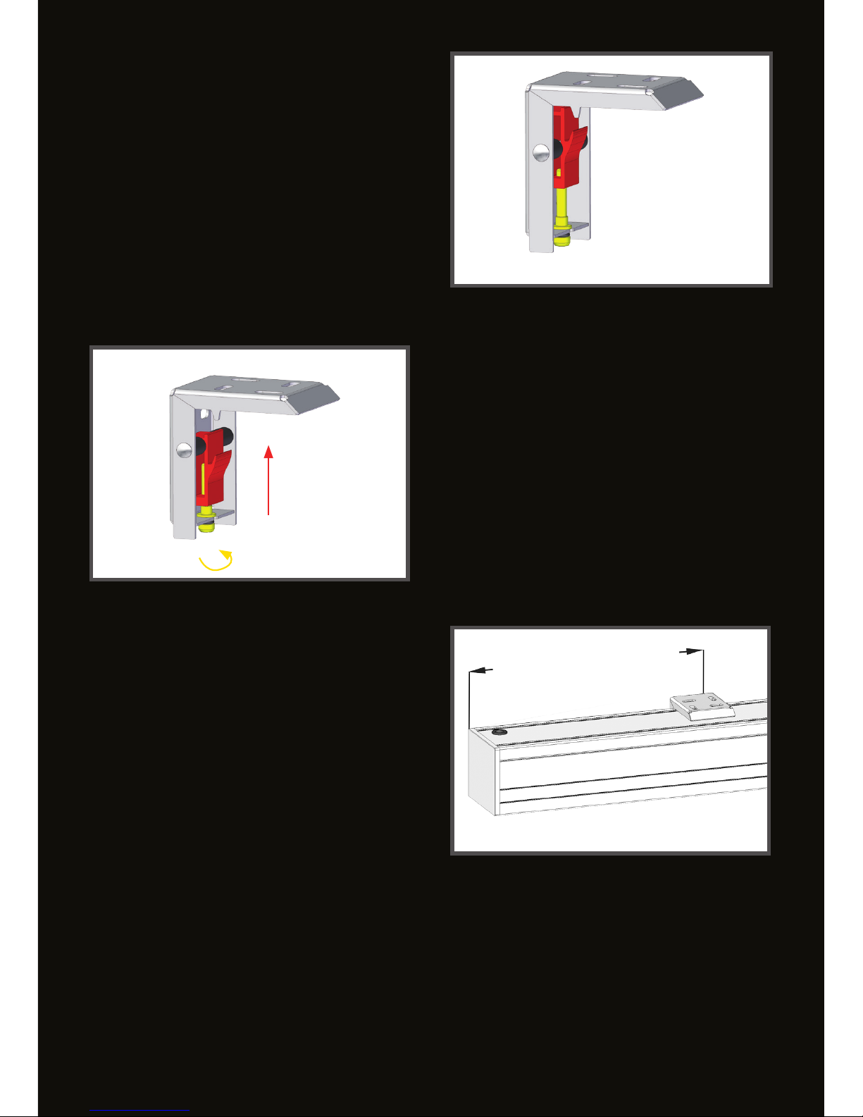
The QuickMount bracket consists of
following main components:
• QuickMount bracket (grey)
• Hook pro le (red)
• Locking screw (yellow)
(sketch showing hook pro le in locking position)
FUNCTIONAL PRINCIPLE
The screen casing is hooked onto the hook
pro le (red), which can be moved
upwards by the locking screw (yellow) to
secure the mounting.
(sketch showing hook pro le in open position)
It is recommended that the QuickMount brack-
ets are positioned on each side within the rst
fth of the screen width. (0,2x WIDTH)
max. 0,2x WIDTH
Page 9
9
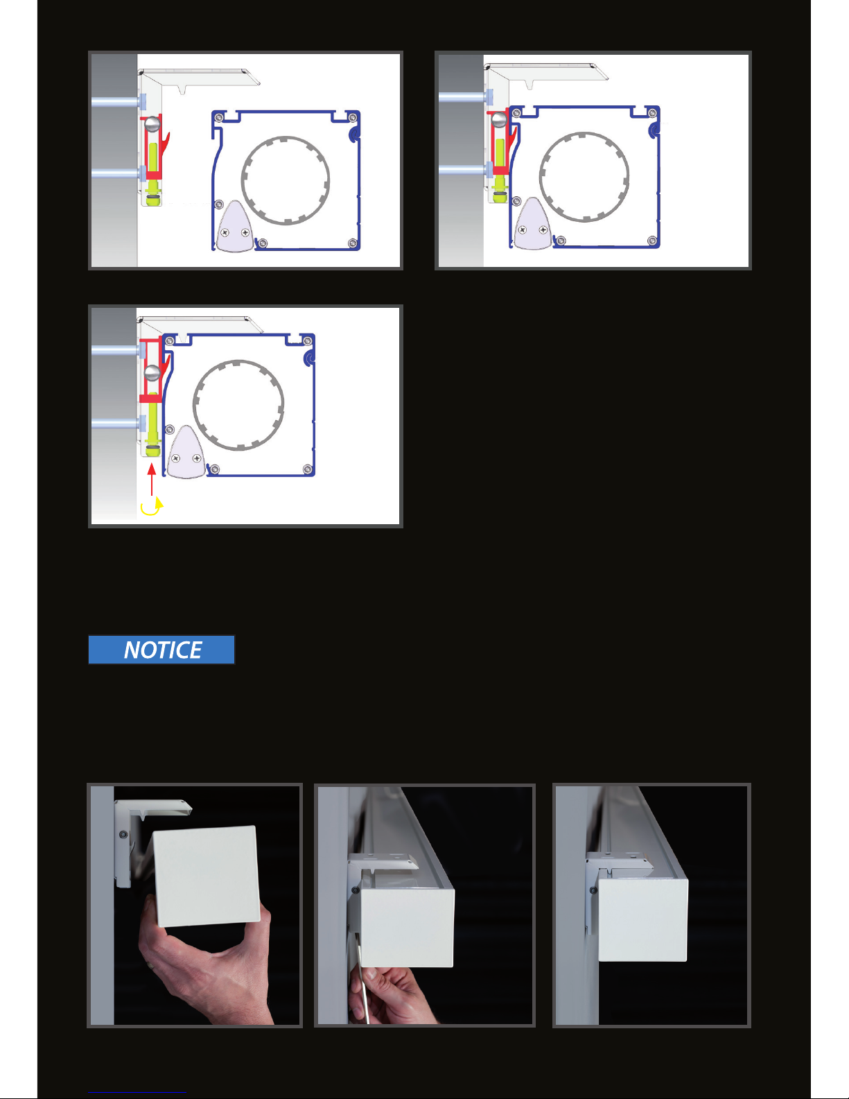
The screen casing (blue) has to be hang up at the
rear recess onto the hook prole (red).
The casing must be lifted towards the upper horizontal part of the QuickMount bracket by turning
the locking screw clockwise, until the safety wedge of the bracket ts into the upper T-slot in the
casing.
QuickMount bracket (white)
QuickMount sliding hookprole (red)
Screen casing (blue)
Locking screw (yellow)
The locking screw must be tightened with low force to avoid deformation of the casing.
Max.torque 3Nm.
Page 10
10
MOUNTING PLATE
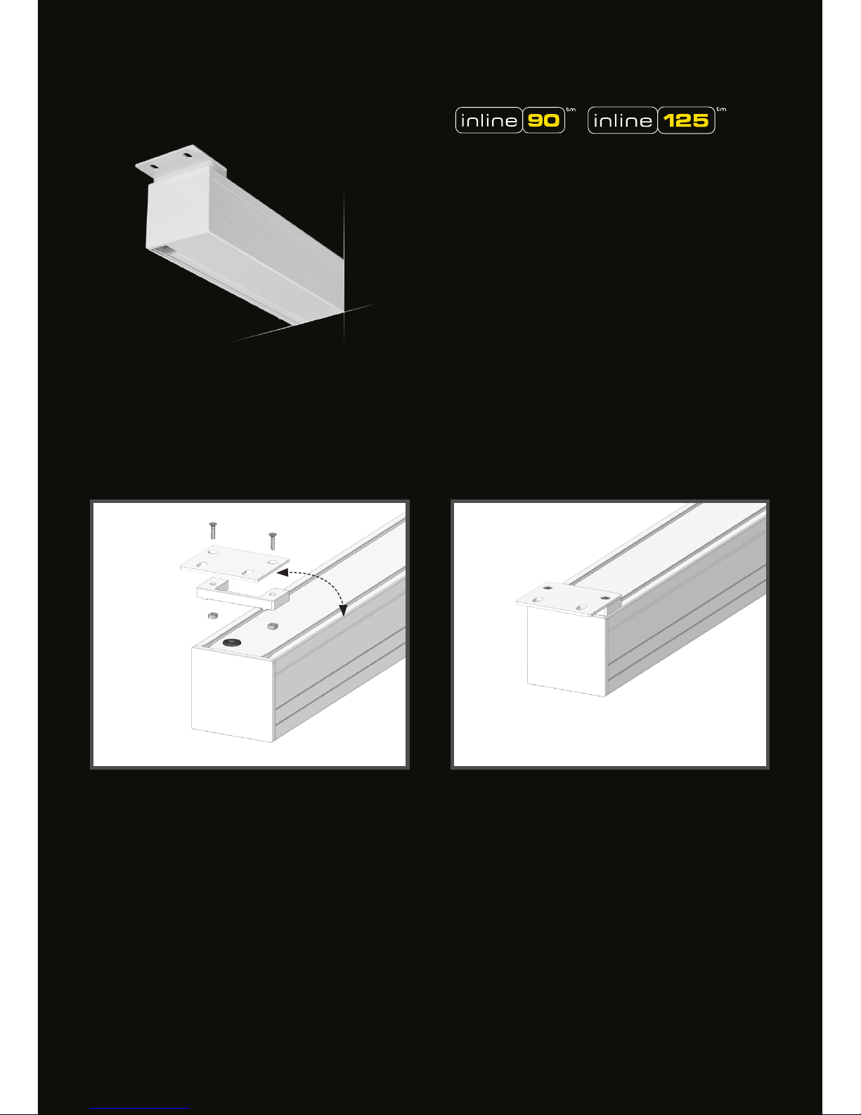
The two mounting plates and the distance elements have to be attached at either sides of the
screencasing with the 2 enclosed countersunk screws and the square nuts M5. (see sketches below)
If necessary, the distance element can be rotated 180 ° to put the motor cable to the left.
INLINE 090 and INLINE 125 can be optionally
delivered with mounting plates for ceiling mounting
Page 11
11
4x
4x
2x
2x
4x
4x
2x
2x
1 2
1 2
UNIVERSAL MOUNTING BRACKETS
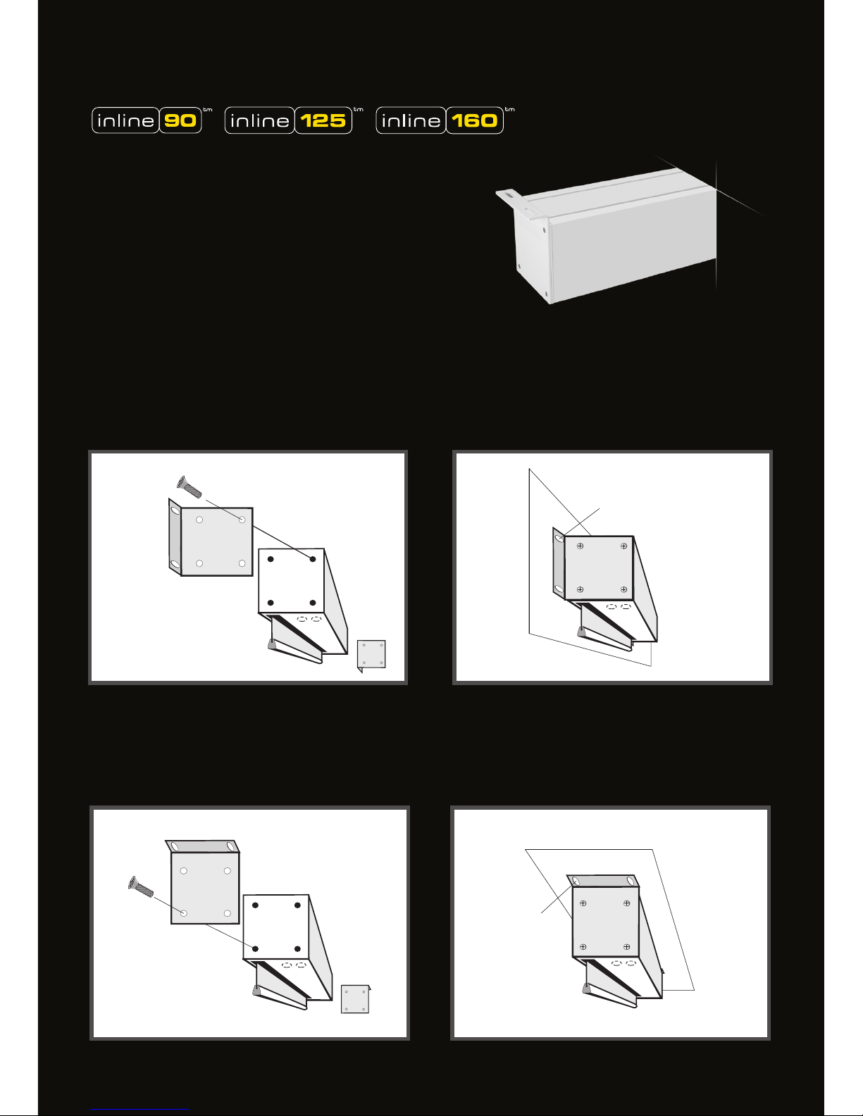
The two mounting brackets have to be attached at either sides of the screen casing with the 4 enclosed Phillips screws. Depending on where the projection screen is mounted to (wall or ceiling), the
brackets have to be attached horizontal or vertical. (see sketches below)
CEILING MOUNTING
INLINE 160 is delivered with universal
mounting brackets, as a standard.
(optional for INLINE 090 and INLINE 125)
WALL MOUNTING
Page 12
12
4x
4x
4x
4x
4x
4x
4x
4x
1 2
1 2
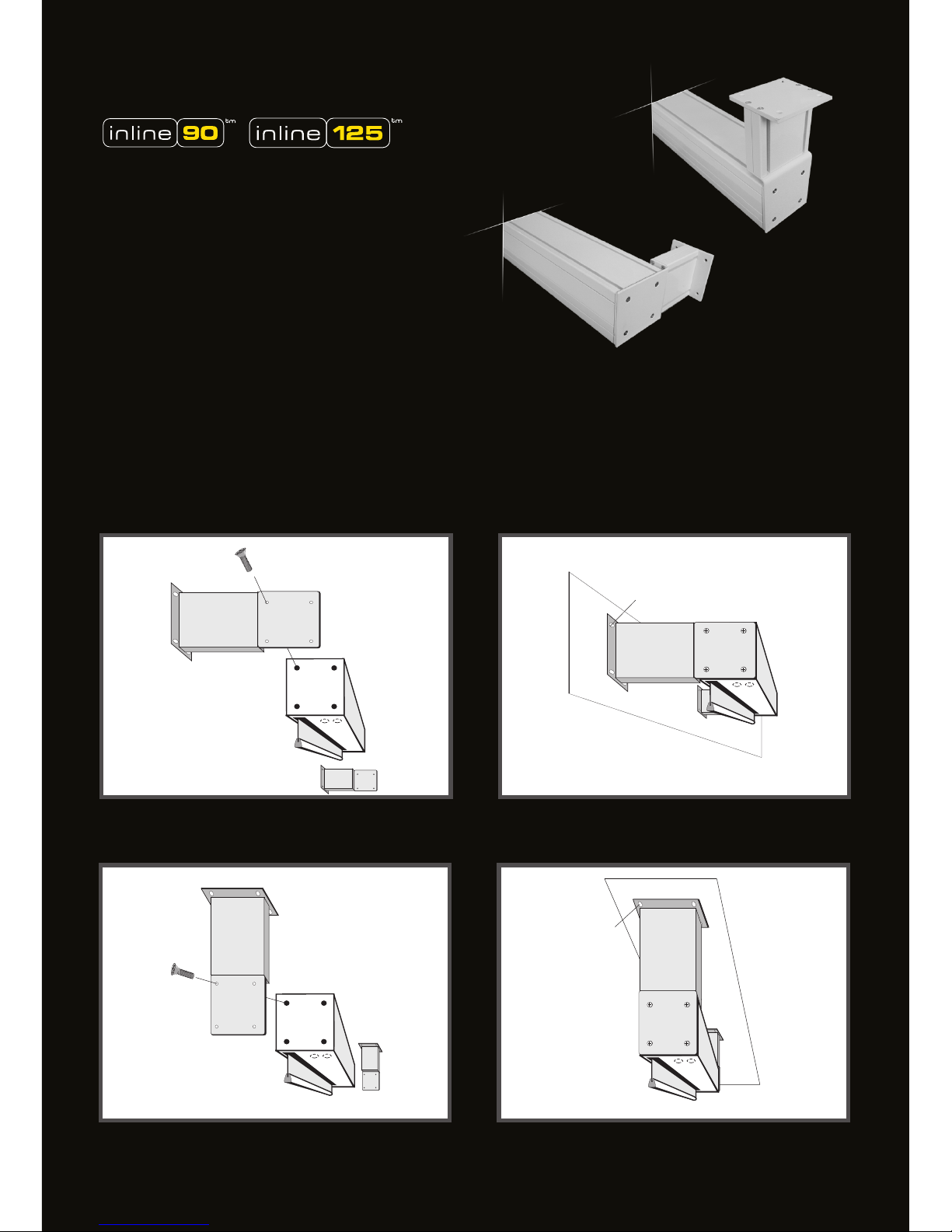
WALL / CEILING BRACKETS
WALL MOUNTING
CEILING MOUNTING
The two wall/ceiling brackets have to be attached at either sides of the screen casing with the 4 enclosed Phillips screws. Depending on where the projection screen is mounted to (wall or ceiling), the
brackets have to be attached horizontal or vertical. (see sketches below)
The INLINE-wall/ceiling bracket can be used for wall
or ceiling mounting because of its horizontal and
vertical mounting option.
Available for INLINE 160 (optional for INLINE 090
and INLINE 125)
Page 13
13
1
2x
2x
4x
4x
4x
1 2
3
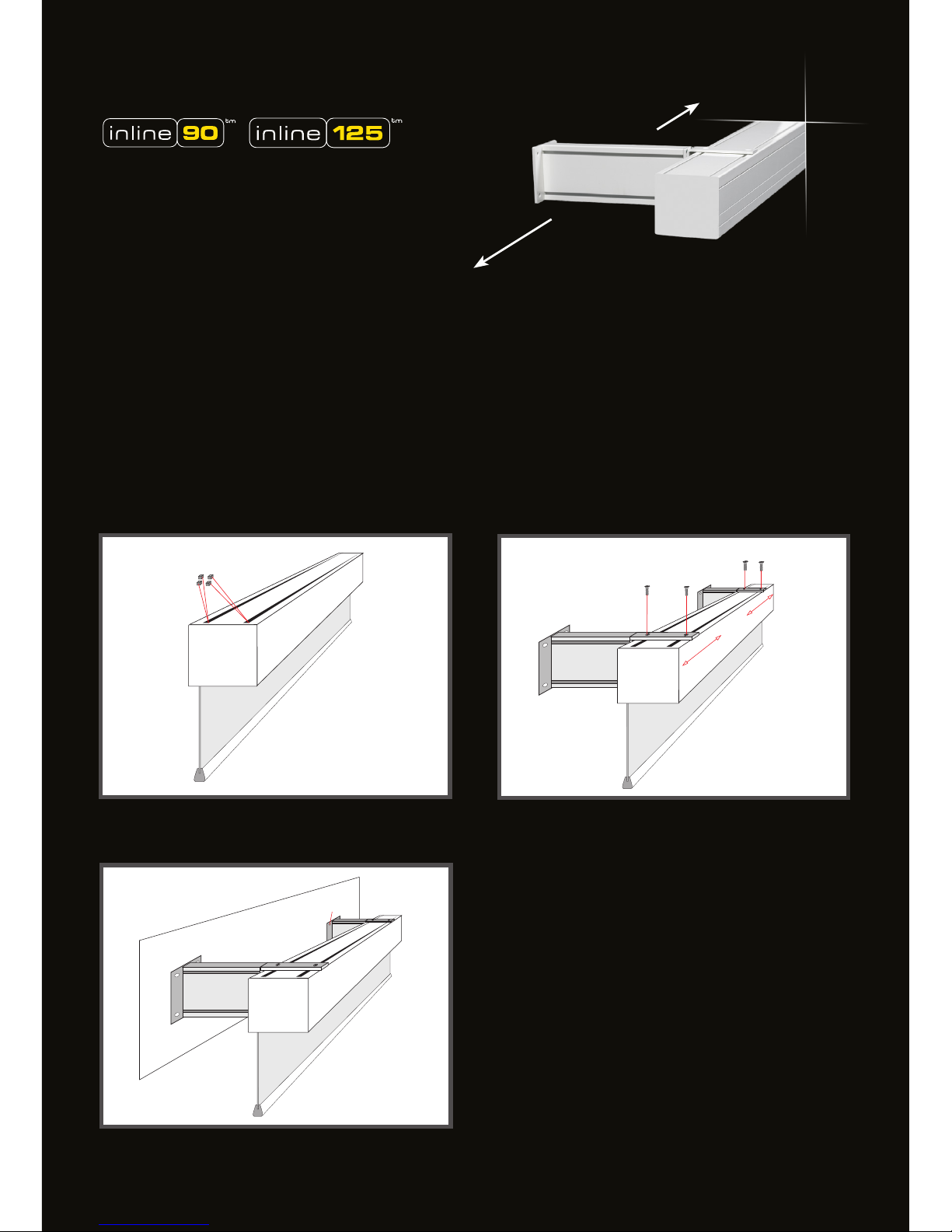
WALL BRACKETS
WALL MOUNTING
Each of the two INLINE-WALL BRACKETS have to be attached at the screen casing with the 2 enclosed
Phillips screws and 2 square nuts M5 for the T-slots. (see sketches below)
The INLINE-WALL BRACKETS can be placed at
any point on the case. Continuous T-slots on the
top provide maximum exibility of mounting.
Available for INLINE 090 and INLINE 125.
Page 14
14
8x
8x
4x
4x
4x
4x
4x
4x
4x
4x
1 2
3
1 2
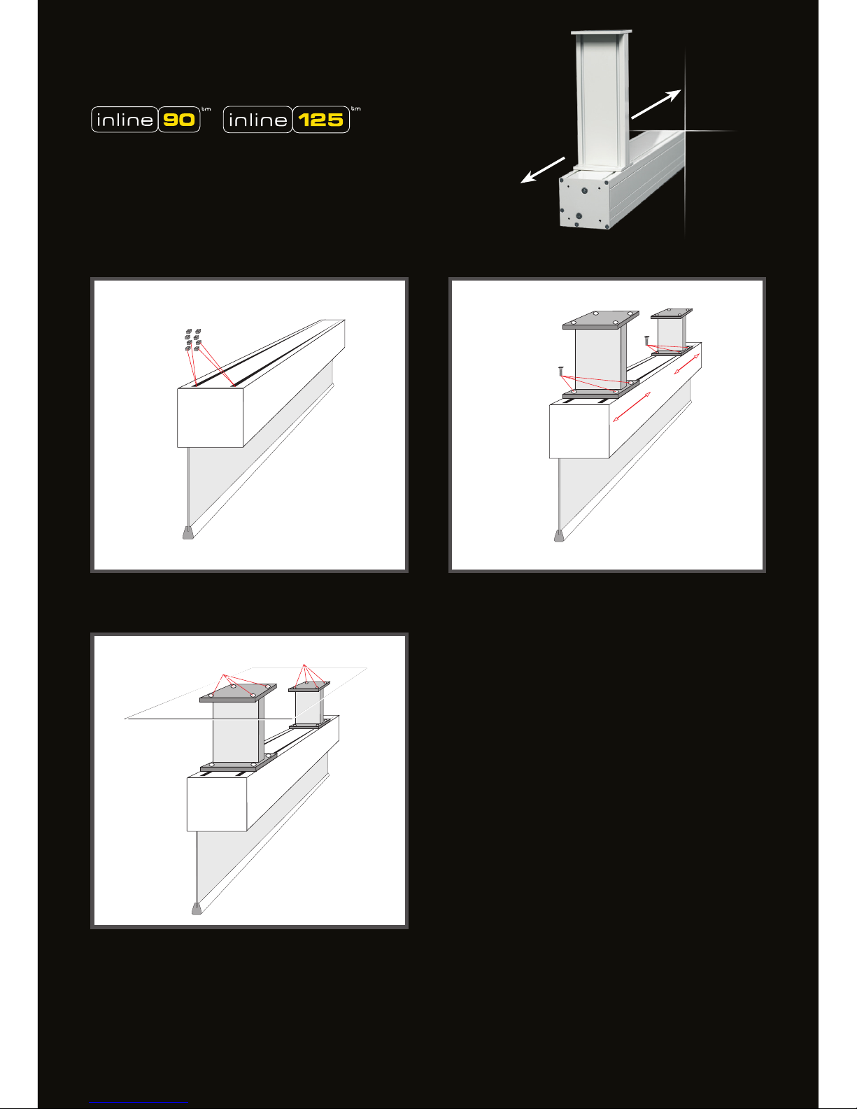
CEILING BRACKETS
CEILING MOUNTING
Each of the two INLINE-CEILING BRACKETS have
to be attached at the screen casing with the 4
enclosed Phillips screws and 4 square nuts M5 for
the T-slots. (see sketches)
The INLINE-CEILING BRACKETS can be placed at
any point on the case. Continuous T-slots on the
top provide maximum exibility of mounting.
Available for INLINE 090 and INLINE 125.
Page 15

15
2
CEILING CASE FOR CEILING INTEGRATION
The installation height is only 92mm!
CEILING CASE with MOUNTING SET
The CEILING CASE can be pre-installed during building works and the screen installation
can be done after building works are completed. Mounting without thread rods, the case is
screwed directly to the concrete ceiling at the connecting plates (red). (see gure)
CEILING CASE without MOUNTING SET
Page 16
16
2
1 2
3
4
5
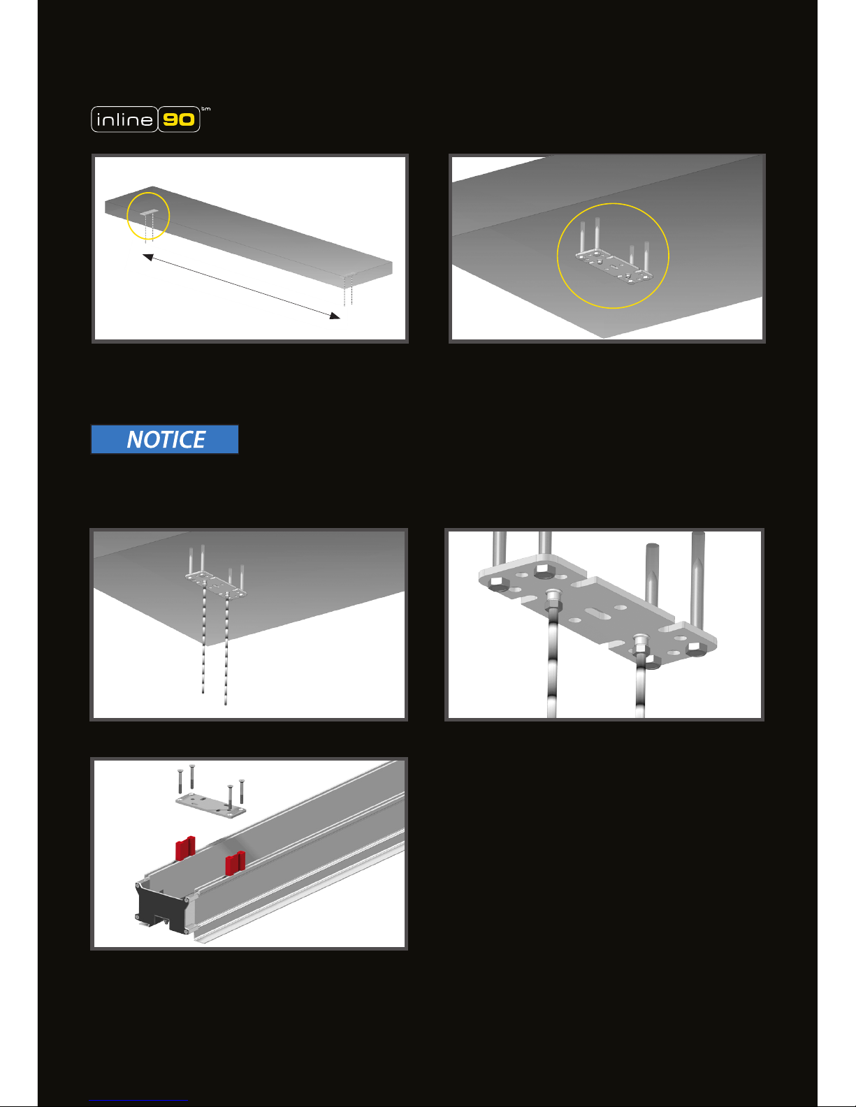
1-2: Parallel and aligned mounting of the two ceiling plates with four screws each. (maximum distance
= fabric width)
CEILING CASE with MOUNTING SET
3-4: Screw in the thread rods into the appropriate
thread inserts against the concrete ceiling and
secure them with the counter nuts.
The thread rods have to be shortened in a
length of 100mm less than the distance between
concrete ceiling and lower edge of the suspended
ceiling.
5: Mounting with thread rods:
The distance elements (red) have to be attached between the CEILING CASE and connecting plates.
Please detach the left and right connecting plate, and position them centered in the distance of the
thread rods. Therefor use the enclosed longer countersunk screws.
Maximum distance = fabric width
Please choose screws which are suitable for the weight of the CEILING CASE with the roll-up screen
and for the wall characteristics.
Page 17
17
4
7
6 7
8
120MM
9
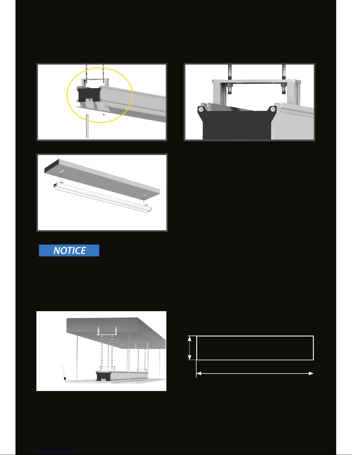
6-8: The CEILING CASE is to be adjusted to
the intended level of the suspended ceiling by
four safety nuts M5. Therefor make use of the
delivered tubular spanner.
Important information for the installation of the suspended ceiling:
It must be ensured that the CEILING CASE is not compressed, to allow the subsequent installation of the
roll-up screen. The CEILING CASE must have a constant opening width of 90.5 mm (3 9/16 inch) over the
entire length to prevent a jamming of the bottom bar of the roll-up screen.
OVERALL LENGTH - 16MM
SUSPENDED CEILING
In case of a subsequent mounting a recess according to the sketch above has to be made.
overall length = fabric width + 152 mm
Page 18
18
10 11
12
13 14
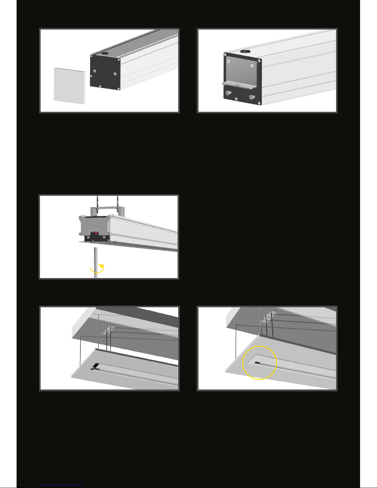
12: The projection screen is then attached on
each of the two thread bolts in the CEILING
CASE with a washer and a lock nut (red).
Please make use of the tubular spanner again.
Roll-Up screens in Quick-Mount version have to be adapted to t into the CEILING CASE.(10-12).
1.Detach the lateral case covers (10).
2. Attach the mounting brackets on both side panels as shown on picture (11).
3.Two at head screws have to be screwed to each side panel acccording to the sketch, to enable the
attachment of the lateral clip brackets (11).
13-14: Finalizing, the two lateral gaps are closed with the clip brackets.
Page 19
19
4
7
14
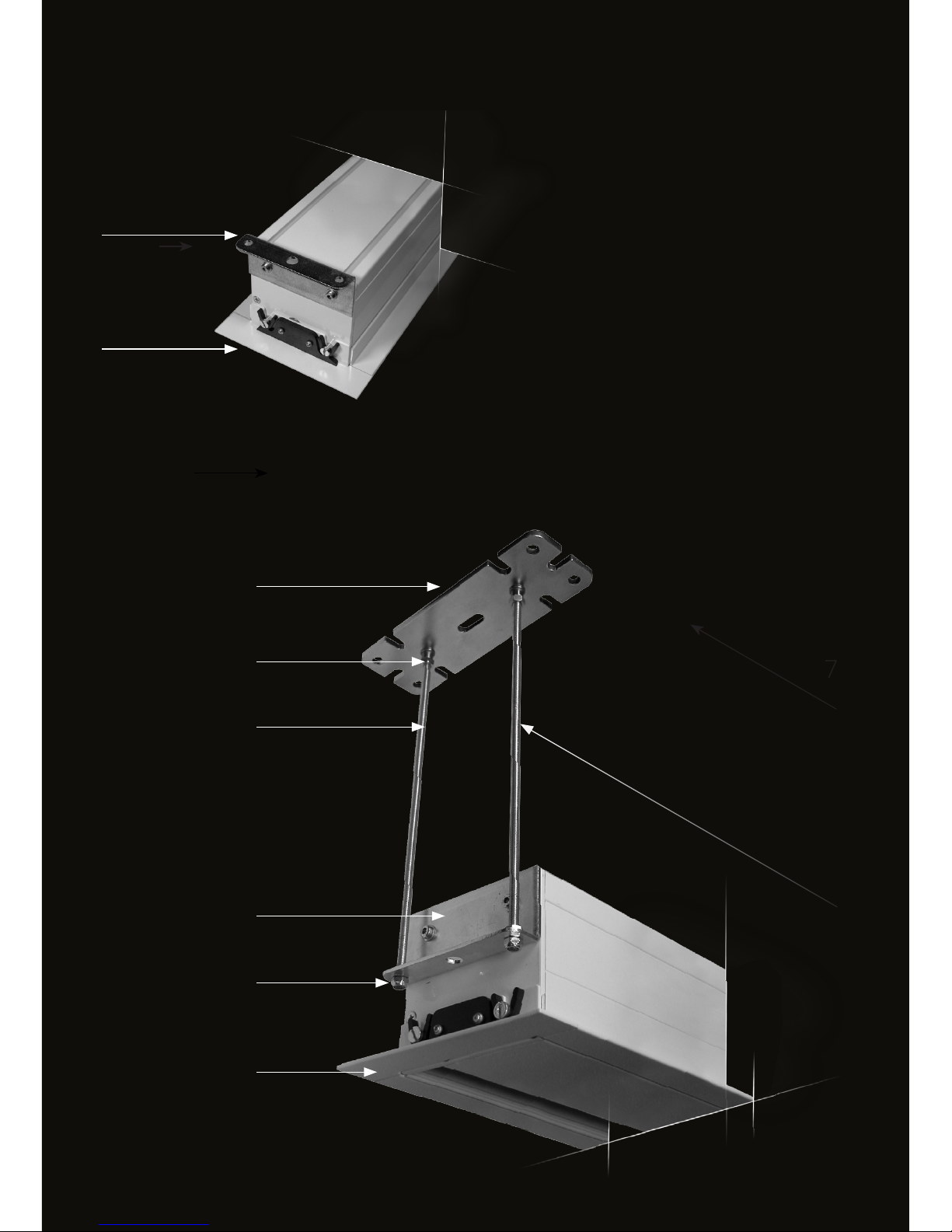
No additional access for servicing needed!
The projection screen can be easily dismount-
ed by taking o the clip covers and detaching
the connection at the mounting brackets.
PROJECTION SCREEN FOR CEILING INTEGRATION
mounting bracket
clip bracket
spacing of mounting brackets
mounting plate
thread rod
counter nut
clip bracket
self lock nuts
mounting bracket
MOUNTING SET for SUSPENDED CEILING
Page 20
20
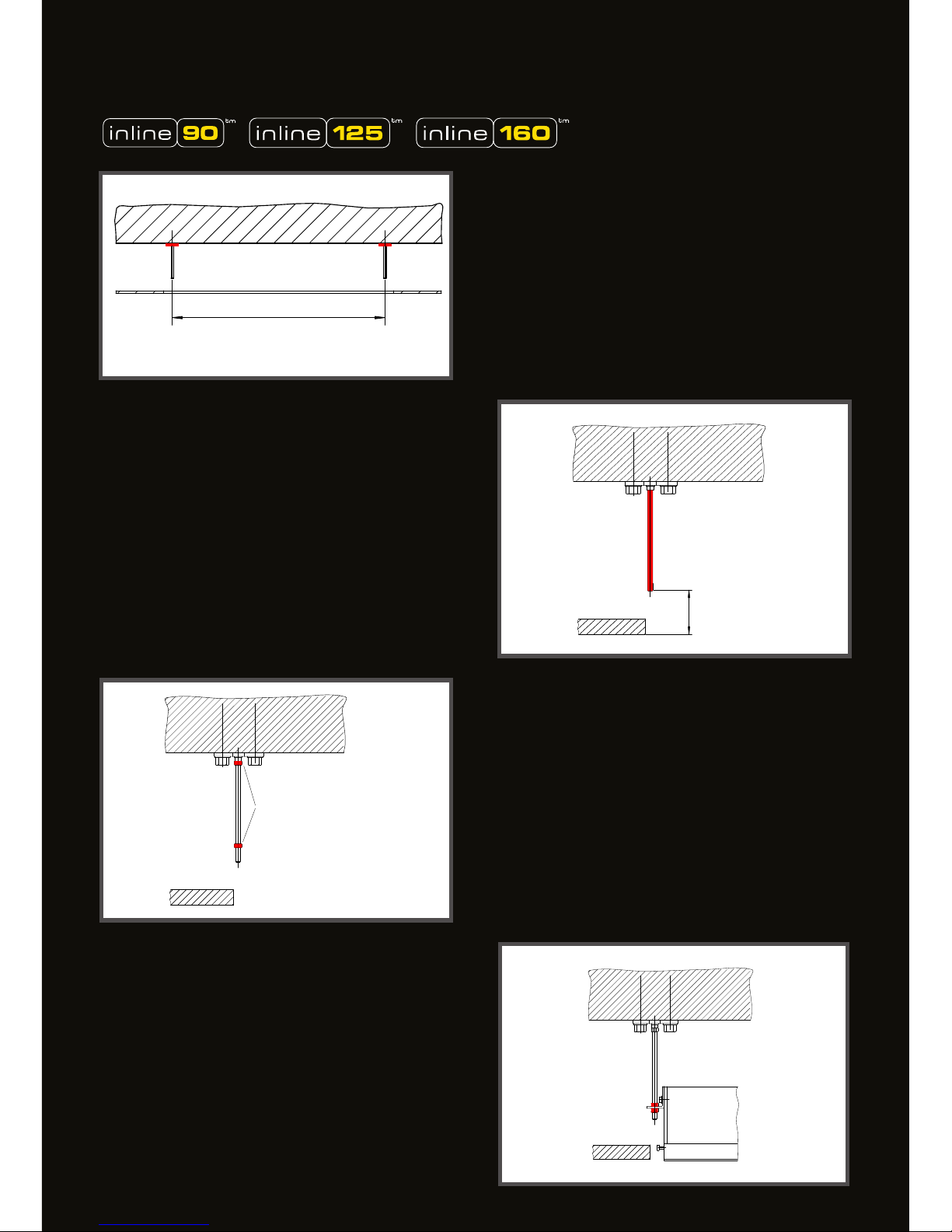
30mm INLINE 090
50mm INLINE 125
90mm INLINE 160
Spacing of the mounting brackets
Lochabstand Montagewinkel
Kontermuttern
counter nut
Kontermutter
counter nut
Sicherheitsmutter
lock nut
MOUNTING SET for SUSPENDED CEILING
1. MOUNTING PLATES
The mounting plates have to be xed
according to the hole pattern of the
projection screen´s mounting brackets.
(see sketch)
2. THREAD RODS
Screw in the thread rods and shorten them
according to the sketch.
3. COUNTER NUT
Screw on a counter nut on either side of the
thread rods. Screw in the thread rods against the
ceiling and secure them with the counter nuts.
4. MOUNTING OF THE PROJECTION
SCREEN
The roll-up projection screen is to be adjusted
to the intended level of the suspended ceiling by
four safety nuts M5. Use the delivered tubular
spanner. After adjustment secure the screen
with the upper counter nuts.
Page 21
21
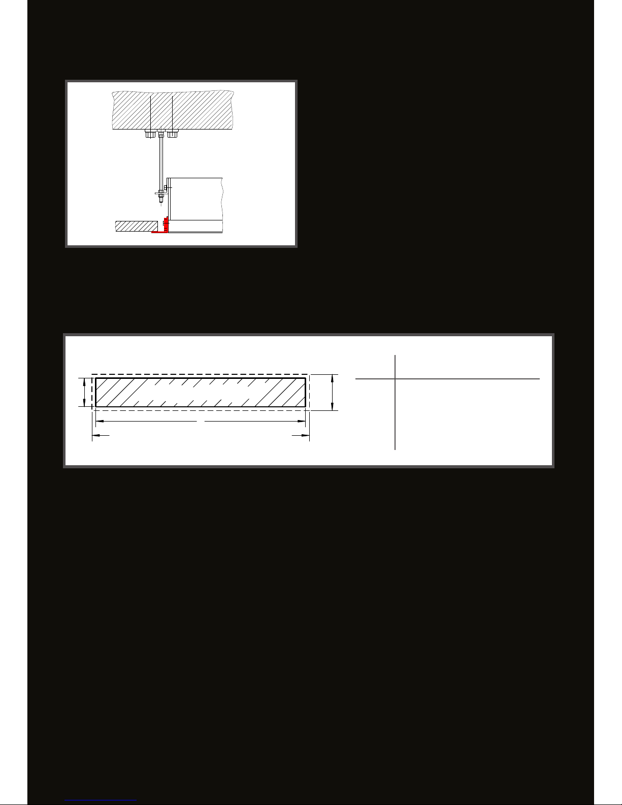
INLINE
GB B Y
090 130mm 105mm 16mm
125 165mm 140mm 24mm
160 220mm 180mm
GB
B
L
Gesamtlänge / overall length
Ausnehmung / recess
L =
Gesamtlänge - Y
overall length - Y
30mm
Clipswinkel
Clip bracket
5. CLIP BRACKET
Final work will be to close the two lateral gaps
with the clip brackets.
In case of subsequent mounting of the projection screen into a suspended ceiling, a recess L x B
according to the screen type has to be made (see sketch above)
RECESS FOR SUSPENDED CEILINGS
Page 22
22
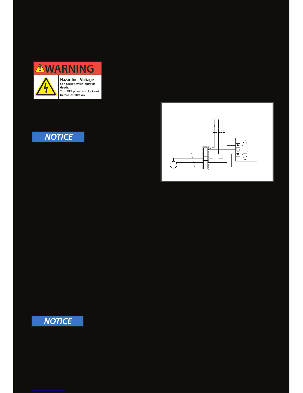
STOP
1
2
3
4
5
M
~
L1 N PE
Inis Uno
Netz / circuit
230V, 50Hz
4x0,75 ²
Abzweigdose
connection box
Antrieb
drive
blu
yel/grn
blk
brn
Abzweigdose
connection box
ELECTRICAL INSTALLATION
The electrical installation has to be done by an authorized electrical
enterprise. Please hand over this information and the wiring regulations, enclosed to each motor and switch or control unit, to the responsible electrician.
SINGLE CONTROL-230V
(See circuit diagram)
Incorrect control of the tube motor results in electrical
overload on the limit switches and may change the set
stop positions. In extreme cases the limit switches may
get welded together permanently. This causes the
motor to be permanently activated and the projection
screen to be damaged.
IN ORDER TO AVOID AN ELECTRICAL OVERLOAD OF THE LIMIT SWITCHES IN THE TUBE
MOTOR, THE WIRING AND THE CONTROL COMMANDS ‚MUST COMPLY WITH THE
FOLLOWING REGULATIONS:
1. DO NOT RUN TWO OR MORE MOTORS IN PARALLEL FROM ONE OUTPUT.
A separate contact must be available for every drive and running direction.
2. SWITCHES AND CONTROLS MUST NOT ALLOW SIMULTANEOUS UP-AND DOWM COMMANDS.
Simultaneous up and down commands cause a short-circuit of the operating capacitor.
For that reason only electrically or mechanically locked single switches (no light switches) must be
used.
3. THE CHANGEOVER-DELAY BETWEEN UP AND DOWN COMMAND MUST BE 500MS AT LEAST.
Switching periods under 0,5s results in extremely high currents, which may result in the limit switches
being welded together and therefore the projection screen being damaged.
OPERATION VIA A MEDIA CONTROL SYSTEM (DRY CONTACT)
In order to control a roll-up screen via a media control system a motor control unit must be installed!
Any damage to the motor and consequential damage caused by non-integration of a motor control
unit are excluded from the warranty.
Motor control unit-> See chapter “Accessories”
Incorrect connection of the projection screen may damage the motor!
ELECTRIC SUPPLY
230VAC 50Hz. Line circuit breaker 10 A. Motor cable 4x0,75mm²
Page 23
23
STOP POSITION ADJUSTMENT
LOSS of WARRANTY
The projection screen is properly adjusted at factory and the adjusting screws are sealed. Changing
of the minimum or maximum nal position is not necessary.
Important: Any damage caused by the adjustment of nal positions is not covered by warranty.
Note: Should it be necessary to adjust the nal positions by applicational reasons, only skilled per-
sonnel is allowed to do so.
Do the adjustment in small steps (one-quarter turn) and check the result by unwind and rewind the
fabric completely.
Tube motors are not suitable for permanent operation; maximum power-on time is 3 - 4 minutes.
When the roll-up screen is running any longer than that, a thermal circuit breaker switches o the
motor. In such a case you need to wait for about 15 minutes before the motor is ready for
operation again!
Page 24
24
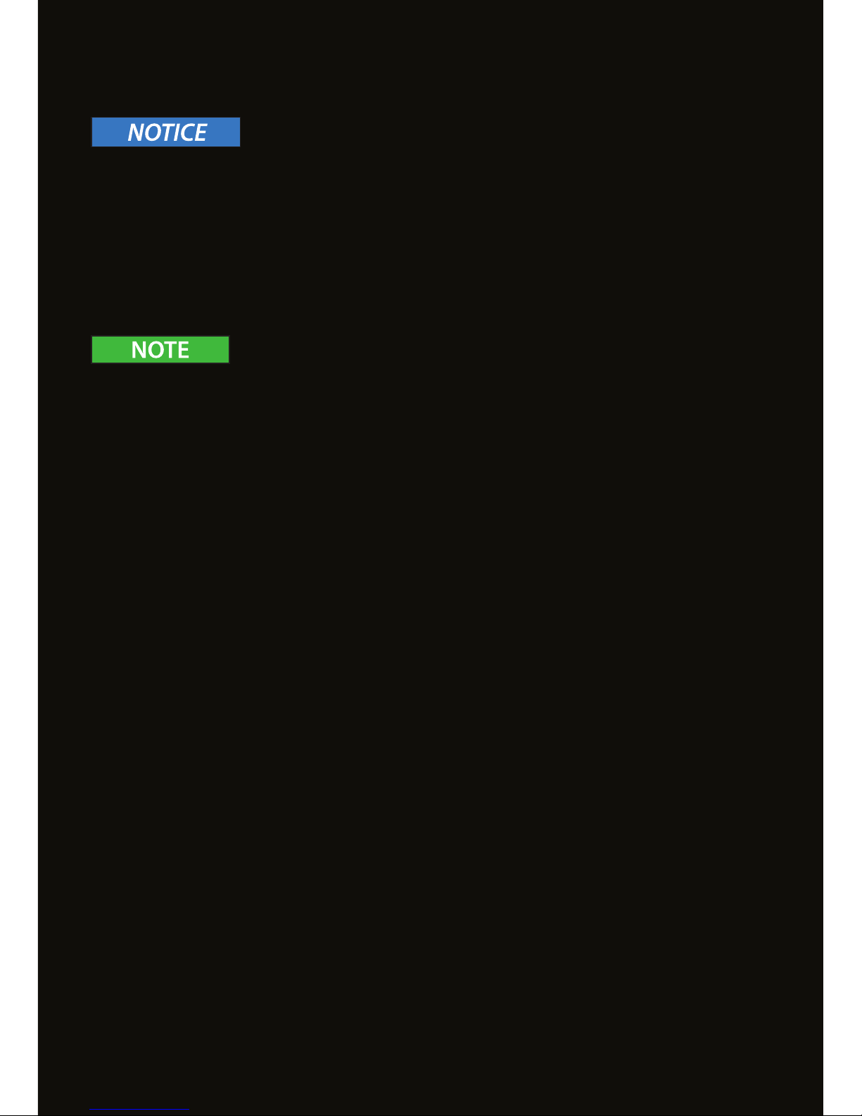
MAX
AUF / UP
AB /
DOWN
WEISS / WHITE
MIN
AUF / UP
AB /
DOWN
GELB / YELLOW
STOP POSITION ADJUSTMENT
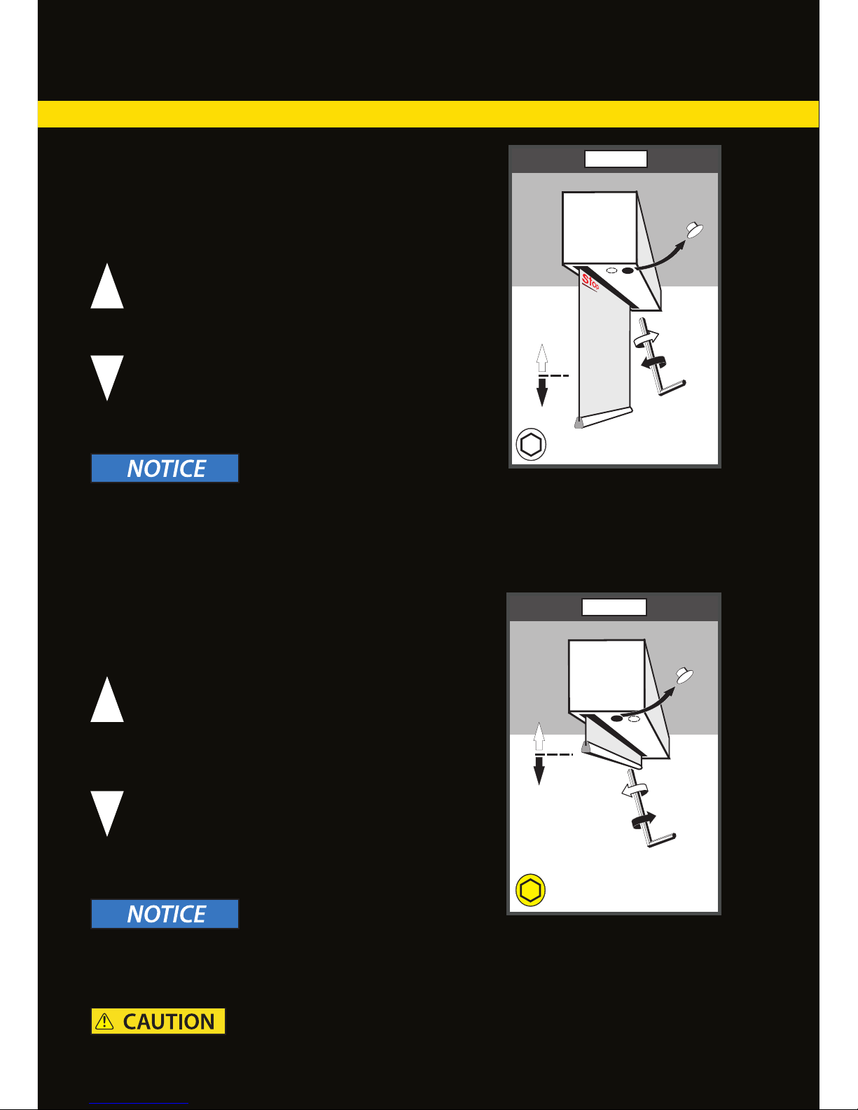
MOTOR LEFT/ FABRIC BACK AND MOTOR RIGHT/FABRIC FRONT
ADJUSTING THE LOWER STOP POINT MAX OF THE
TUBE MOTOR
Remove the round cover cap at the bottom of the screen
casing (see Fig. MAX).
ADJUSTMENT OF THE FINAL POSITION MIN:
Remove the round cover cap at the bottom of the screen
casing (see Fig. MIN).
IN ORDER TO MOVE THE STOP POINT MAX UP
YOU NEED TO TURN THE WHITE SET SCREW TO
THE RIGHT (CLOCKWISE) (SEE FIG. MAX)
IN ORDER TO MOVE THE STOP POINT MAX
DOWN YOU NEED TO TURN THE WHITE
SET SCREW SLIGHTLY TO THE LEFT (COUNTER-CLOCKWISE) (SEE FIG. MAX)
IN ORDER TO MOVE THE STOP POINT
MIN SLIGHTLY UP YOU NEED TO TURN
THE YELLOW SET SCREW SLIGHTLY TO
THE LEFT (COUNTER-CLOCKWISE) (SEE
FIG. MIN).
IN ORDER TO MOVE THE STOP POINT
MIN DOWN YOU NEED TO TURN THE
YELLOW SET SCREW TO THE RIGHT
(CLOCKWISE) (SEE FIG. MIN).
The STOP mark must not be visible! There is a risk of the projection screen material is
ripped o the winding tube and irreparable damage being caused.
The screen material and/or the bottom bar falling down may cause injuries to persons within the
danger area below the projection screen.
The STOP mark must not be visible! There is a risk of the projection screen material is ripped o the
winding tube and irreparable damage being caused.
Page 25
25
MAX
AUF / UP
AB / DOWN
GELB / YELLOW
MIN
AUF / UP
AB / DOWN
WEISS / WHITE
STOP POSITION ADJUSTMENT
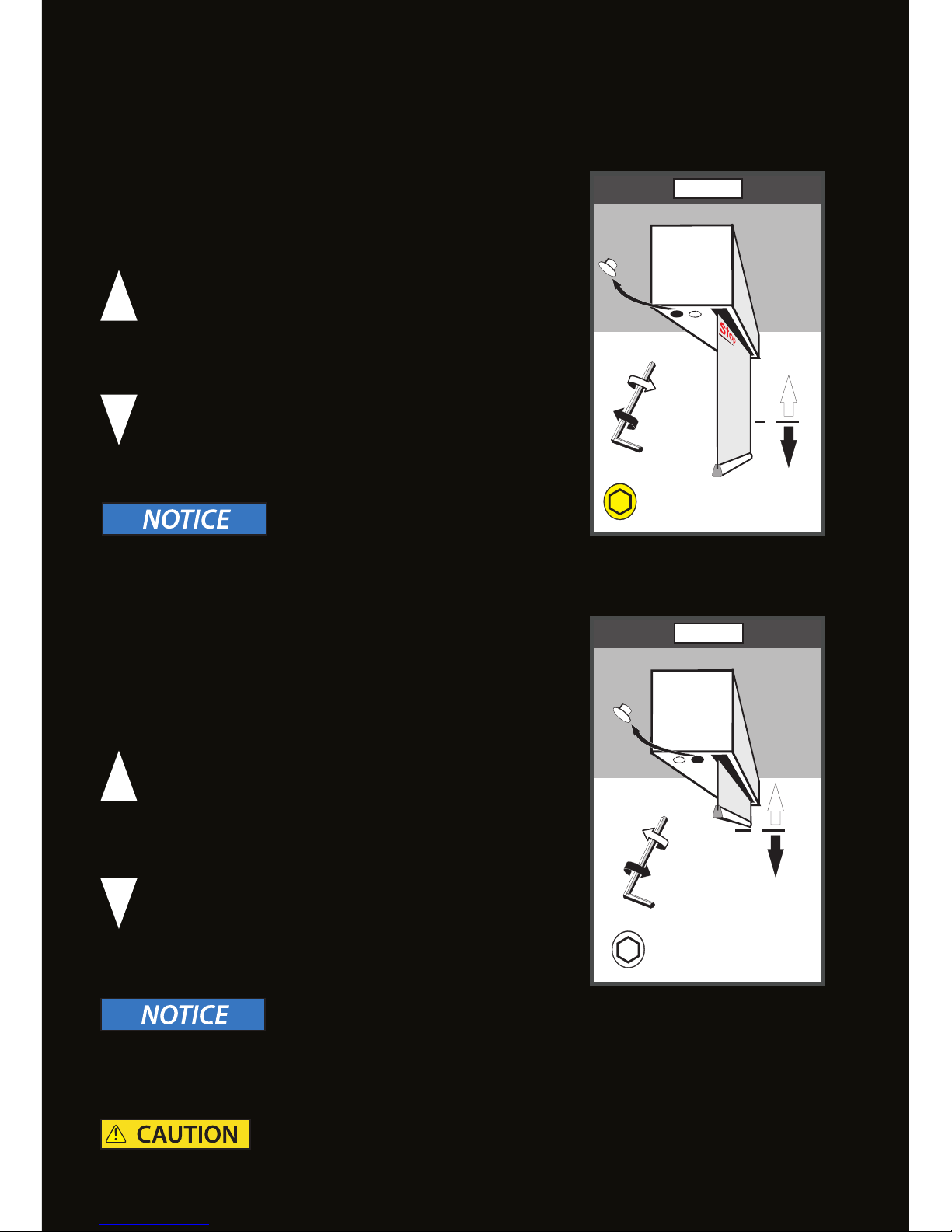
MOTOR LEFT/ FABRIC FRONT AND MOTOR RIGHT/FABRIC BACK
ADJUSTMENT OF THE FINAL POSITION MAX:
Remove the round cover cap at the bottom of the screen
casing (see Fig. MAX).
ADJUSTMENT OF THE FINAL POSITION MIN:
Remove the round cover cap at the bottom of the screen
casing (see Fig. MIN).
IN ORDER TO MOVE THE STOP POINT MAX UP
YOU NEED TO TURN THE YELLOW SET SCREW
TO THE RIGHT (CLOCKWISE) (SEE FIG. MAX)
IN ORDER TO MOVE THE STOP POINT MAX
DOWN YOU NEED TO TURN THE YELLOW SET
SCREW SLIGHTLY TO THE LEFT
(COUNTER-CLOCKWISE) (SEE FIG. MAX)
IN ORDER TO MOVE THE STOP POINT
MIN SLIGHTLY UP YOU NEED TO TURN
THE WHITE SET SCREW SLIGHTLY TO THE
LEFT (COUNTER-CLOCKWISE) (SEE FIG.
MIN).
IN ORDER TO MOVE THE STOP POINT
MIN DOWN YOU NEED TO TURN THE
WHITE SET SCREW TO THE RIGHT
(CLOCKWISE) (SEE FIG. MIN).
The bottom bar of the screen material must not be pulled into the opening of the screen casing!
There is a danger that the bottom bar will be ripped o from the screen material and falls down.
The screen material and/or the bottom bar falling down may cause injuries to persons within the
danger area below the projection screen.
The STOP mark must not be visible! There is a risk of the projection screen material is ripped o the
winding tube and irreparable damage being caused.
Page 26
26
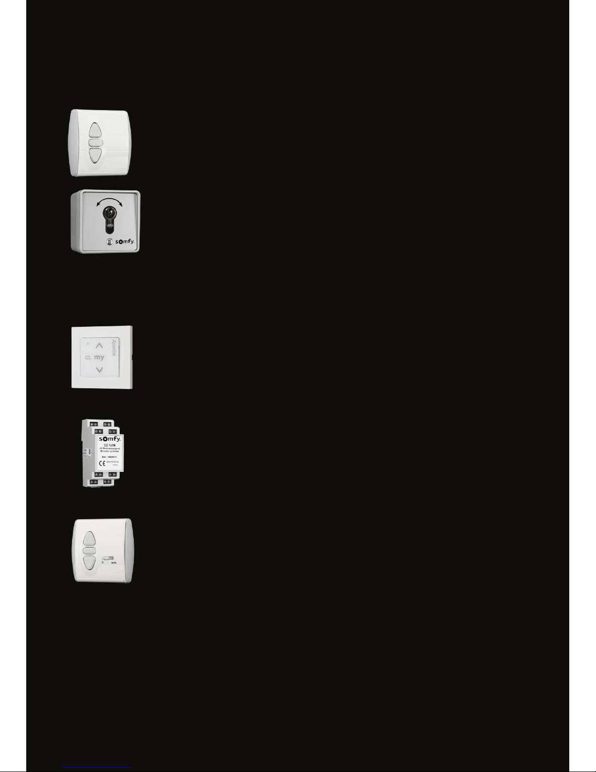
ACCESSORIES
CONTROL OF ONE MOTOR
BRZ-S-SW-INIS-UNO:
Wall switch, for controlling a motor drive; Surface mounted and ush mounted
(UP-STOP-DOWN)
BRZ-S-SW-KEY-UPAP
Key switch, for controlling a motor drive; Surface mounted and ush mounted
(UP-STOP-DOWN)
MEDIA CONTROL (DRY CONTACT)
BRZ-S-MC-CEN-UNO-RTS:
Motor control unit button, combination with safety insert,
2 intermediate positions programmable, surface mounted and ush mounted
BRZ-S-MC-SMO-UNO-IB:
Motor control unit for ush mounting with integrated switch,
2 intermediate positions programmable
BRZ-S-MC-CD1X1N:
Motor control unit, with dry contacts and with safety insert to
protect the motor from impermissible control commands (version for
mounting on a 35mm DIN rail in distribution cabinets). Optional push button
possible.
Page 27
27
You will nd detailed information for our further control options
on our website::
www.AVstump.com/controls
ACCESSORIES
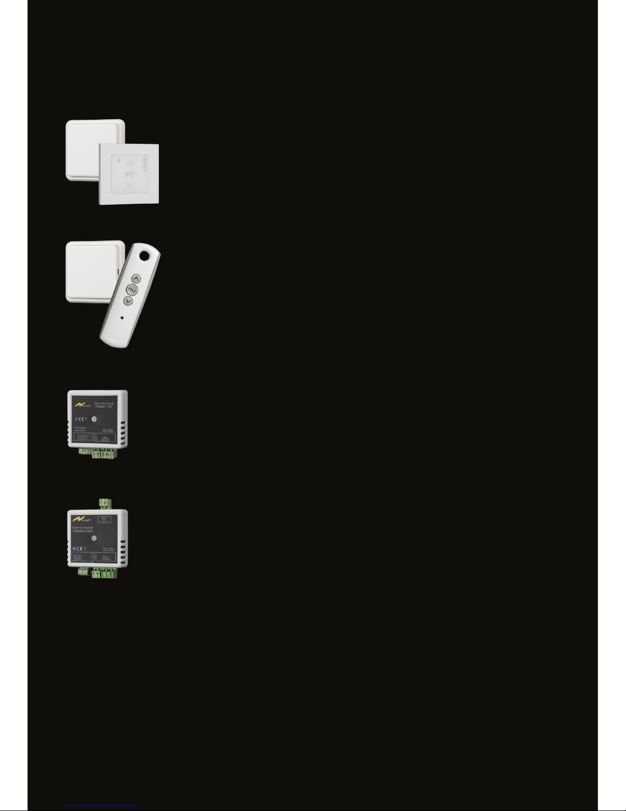
RADIO CONTROL
SOMFY RADIO CONTROL-SET (BRZ-S-RC-SET-SMO-ORI):
consisting of radio receiver Centralis Indoor RTS for ush mounting
and remote control Smoove 1 Origin RTS for wall mounting.
SOMFY RADIO CONTROL-SET (BRZ-S-RC-SET-TELIS1):
Consisting of radio receiver Centralis Indoor RTS for ush mounting
And remote control Telis 1.
(Optional: Telis 4 ... four channels, wall-mounted adapter)
TRIGGER 12V (BRZ-S-TRIGGER-12V)
for controlling the projection screen via a projector with trigger output. Direct
control of the projection screen via optional switch possible.
TRIGGER 230V (BRZ-S-TRIGGER-230V)
For controlling the projection screen via a projector without trigger output.
Direct control of actuators via optional switches possible.
Page 28
28
MIN
AUF / UP
MAX
AB / DOWN
MANUAL ROLL-UP SCREENS
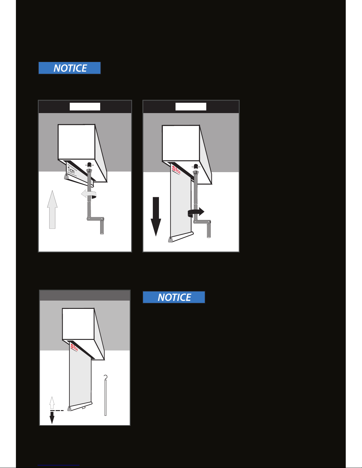
Do not unwind beyond the STOP-limit! Do not pull the bottom bar into the casing !
SPRING-ROLLER MECHANISM WITH SOFT-REWIND
Unwind:
Guide down the fabric with or without the pull bar on the
handle. Stopping the unwind procedure the fabric stays in the
respective height after 3 seconds.
Rewind:
Pull down the handle a few centimeters and let the fabric
rewind automatically.
CRANK MECHANISM
Do not pull down the fabric beyond the STOP-mark!
There is a risk of the projection screen material is ripped o
the winding tube or the soft rewind mechanism being locked
permanently and irreparable damage being caused.
Page 29
29
1 2
3
AV Stump GmbH | Mitterweg 46 | 4702 Wallern
AVstump@AVstump.com | www.AVstump.com | +43 7249 42811
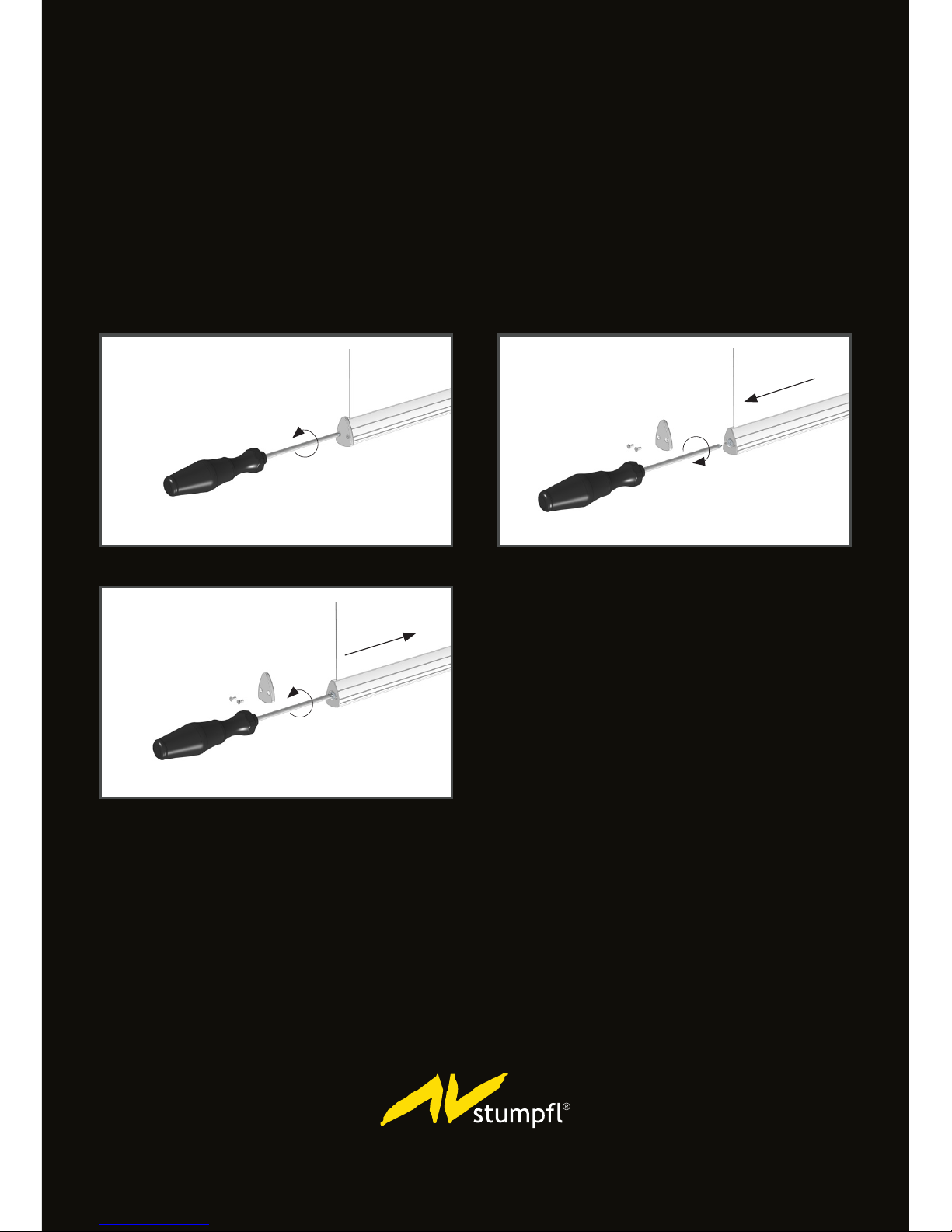
TENSIONING UNIT
Any changes in the room climate (temperature, humidity, winter/summer) may cause the screen
material to slight expand or shrink and result in some sort of waviness near the bottom bar.
Rollup projection screens INLINE and MAGNUM oer the possibility to compensate for these
changes by adjusting the tension on the bottom bar.
1 Unscrew the two Phillips screws and remove the end caps. Behind these end caps you will nd the
central set-screw.
2 Turning this screw clockwise increases the tensile stress.
3 Turning the screw counter-clockwise reduces the tensile stress..
Page 30

 Loading...