

Page 1
THE WORM
3D RGB LASER
Order ref: 152.765UK
User Manual
IMPORTANT SAFETY NOTICE
Please Read this manual before operating
VERSION 1.0
Page 2

Caution: Please read this manual carefully before operating
Damage caused by misuse is not covered by the warranty
Introduction
Thank you for choosing THE WORM laser as part of your effects lighting equipment. This
product has been designed to create pin sharp 3D geometric patterns in 7 colours with a full
range of twisting and rotating movement. Please read and retain this manual in order to
achieve the best results from your purchase and avoid damage through misuse.
High quality scanning for pin sharp 3D moving effects
RGB mixing for up to 7 colours
0.3W total laser power (Red: 150mW, Green: 50mW, Blue: 100mW)
Auto, sound-activated modes
17 channel DMX operation
Master/slave mode
Supplied with I.R remote control
Easy digital display to set the mode of operation
Key controlled for laser safety
We recommend that this product is used within the guidelines HSG95
152.765UK User Manual
Page 3
CAUTION
Please read this manual fully before installing or operating this product as it contains
important safety information relating to its installation and operation.
This Class 3B laser product emits hazardous levels of optical radiation and will
cause injury to the eyes if viewed directly.
This product is not suitable for projection directly at audiences or other personnel.
This product must not be used for any form of audience scanning application and is for
professional use only.
Important information
This product is a Class 3B laser and should only be installed and used by personal who are
trained in the management of laser radiation and are able to operate in accordance within the
guidance given by the Health and Safety Executive (HSE) in HS(G)95: “The Radiation Safety of
Lasers used for Display purposes”.
Copies of this guide can be downloaded from the HSE website:
www.hse.gov.uk/pubns/priced/hsg95.pdf
This product contains no user-serviceable parts. Under no circumstances should any attempt
be made by the user to dismantle or modify it in any way.
152.765UK User Manual
Page 4
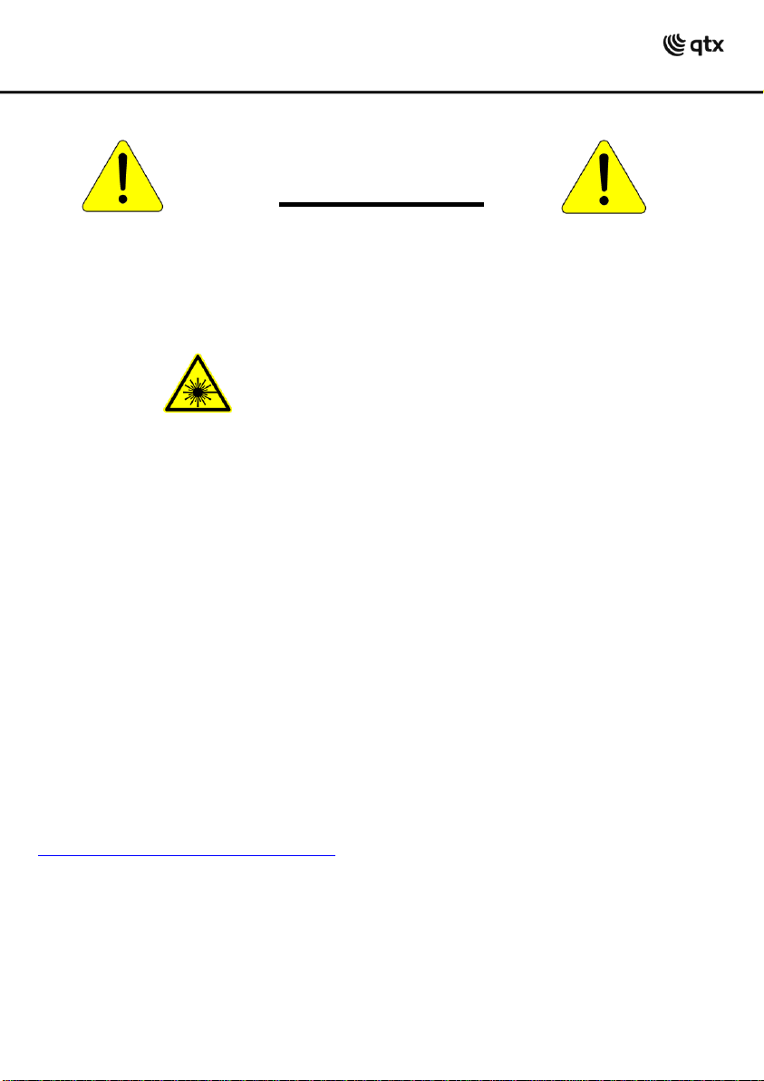
Installation instructions
This product must be securely mounted with adequate fixings to hold the weight. If mounted
at height, use a safety wire attached to the eyebolt and a secondary fixing point. Position the
aperture so that its emission is always directed away from people and objects that are able to
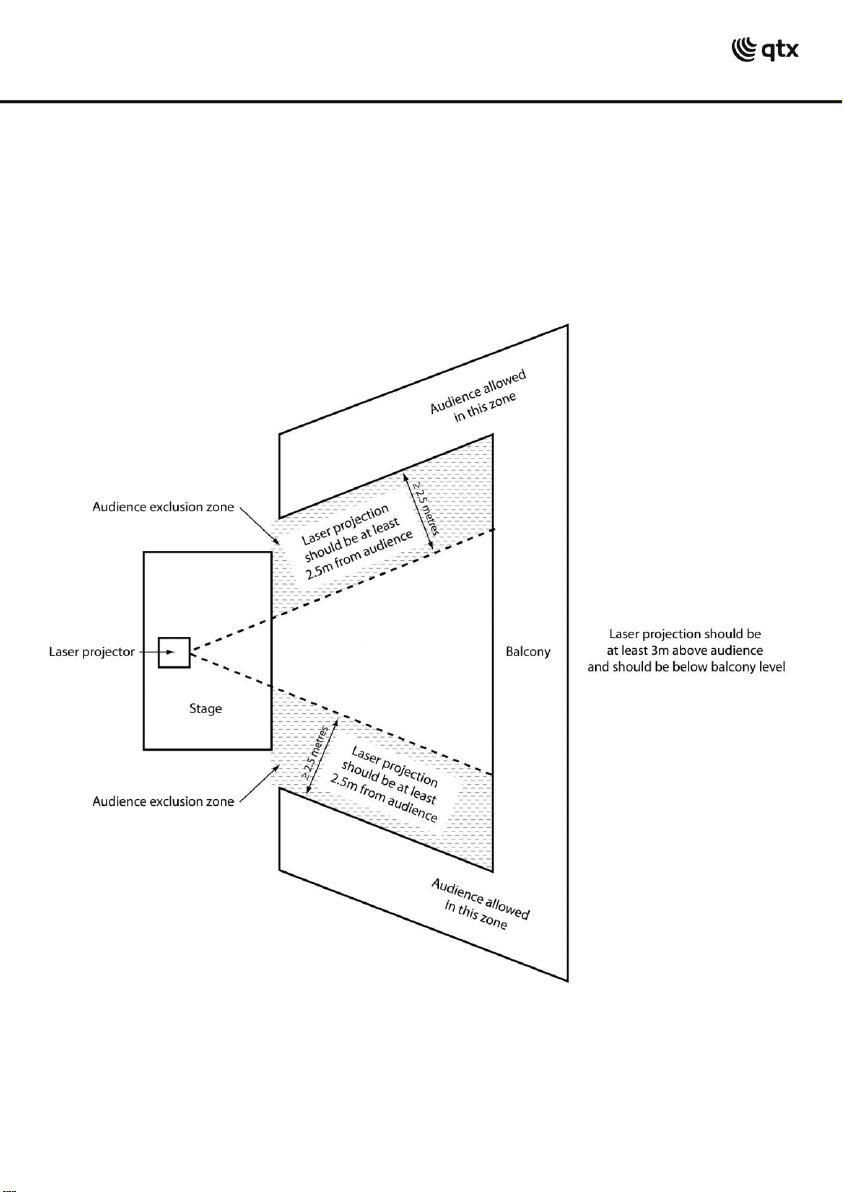
reflect the emission towards people. In this regard the separation distances of 3 metres
vertically and 2.5 metres horizontally, cited in HS(G)95 and shown below must be observed.
Vertical bird’s eye view
152.765UK User Manual
Page 5
Laser x 1unit
I.R. remote control x 1pc
IEC Power Lead x 1pc
Safety Keys x 2pcs
Vertical cross sectional view
Unpacking
Please check the contents to ensure that the product has been received in good condition.
If you find any accessory is missing or the product has arrived with any problems, please
contact your retailer at once.
This product contains no user-serviceable parts so make no attempt to try to fix or modify this
item yourself as this will invalidate the warranty. We recommend you keep the original
package and proof of purchase for any possible replacement or returned demand.
152.765UK User Manual
Page 6

Setting up
1. Unpack the laser ensuring all packaging and tape is removed.
2. Always test the laser before fixing in a permanent location.
3. Connect the IEC mains plug and switch the rear power switch on.
4. Insert the safety key and turn to a quarter turn clockwise. At this point ensure that no
one is exposed to laser radiation.
5. Select which mode you want to operate the laser in.
6. Leave the laser to run for 10 minutes before installing in its location.
Installation
When mounting at height, attach a safety wire to the eyebolt with an independent fixing.
Use the integral mounting bracket with a suitable clamp for stand or truss being fixed to.
When mounting directly to ceiling surfaces, be sure to use adequate fixings for the supporting
material.
152.765UK User Manual
Page 7

Connecting to mains, earth wire (ground) must be connected.
Wire
Connection
International symbol
Brown
Live
L
Blue
Neutral
N
Yellow /Cyan
Earth
Use the supplied IEC lead to connect to the main power supply as follows:
For your safety, please kindly pay attention to all of the warnings below:
Always plug in the power plug last and disconnect from the mains when the device is
not in use or before cleaning.
Do not install and operate the device in rain or extreme heat, moisture or dusty
environments.
This device is for indoor use only and in a dry environment.
Do not switch on immediately. Wait until the unit reaches room temperature.
Do not shake the device and avoid brute force when installing or operating.
Do not use the device during thunderstorms and please disconnect the power.
Do not use solvents or aggressive detergent to clean the device. Use a soft and clean
cloth.
Do not modify the device or the connected power cord without authorisation.
Do not stare into the aperture. This product emits hazardous levels of optical radiation
and will cause serious injury to the eyes if viewed at close range.
This product should be securely mounted so that its output emission is always directed
away from people and at objects that are able to reflect emission towards people. In
this regard, the separation distances cited in HS(G)95 should be observed.
The symbol determines the minimum distance from lighted objects. The
minimum distance between light-output and the illuminated surface must be more than
0.5m.
152.765UK User Manual
Page 8

Replacing the fuse
First disconnect from the mains power supply then remove the fuse holder above the IEC
Socket to reveal the fuse. Replace with the correct fuse rating as stated on the product or in
the user manual. Then lock the fuse holder cover back into place.
General maintenance
Be sure to power off the fixture before conducting maintenance.
To maintain optimum performance and minimise wear, fixtures should be cleaned frequently.
Usage and environment are contributing factors in determining frequency. As a general rule,
fixtures should be cleaned at least twice a month. Dust build-up reduces light output &
performance as well as overheating. This can lead to reduced life and increased mechanical
wear.
Unplug fixture from power. Use a vacuum or air compressor and a soft brush to remove dust
collected on external vents and internal components. Clean all glass when fixture is cold with a
mild solution to the cloth or tissue, and drag dirt and grime to the outside of the lens. Gently
polish optical surfaces until they are free of haze and lint.
The cleaning of internal and external optical lenses and/or mirrors must be carried out
periodically to optimise light output. Cleaning frequently depends on the environment in which
the fixture operates: damp, smoky or particularly dirty surroundings can require cleaning fluid.
Always dry the parts carefully. Clean the external optics at least every 20 days.
152.765UK User Manual
Page 9

Front panel
1.
Cooling fan (do not cover)
2.
Power LED
3.
I.R. remote receiver
4.
Music LED
5.
Laser aperture
6.
Control panel
7.
Safety eyebolt
8.
DMX output
9.
DMX input
10.
Remote power connection
11.
Safety key switch
12.
IEC mains inlet
13.
Mains fuse holder
14.
Power On/Off switch
Rear Panel
Control panel
The control panel and display allow the user to adjust settings as follows…
Press FUNC to navigate through the options
Press ENTER to select an option and adjust value using UP and DOWN buttons
Press ENTER again to confirm setting
152.765UK User Manual
Page 10

Control panel options
Display
Mode
Press ENTER for setting (press FUNC to exit)
/
Auto or Sound mode
= auto sequence through patterns
= sound-activated sequence through patterns
Microphone sensitivity
(minimum) to (maximum)
DMX start address
to
Slave mode
= direct slave mode (mimics master unit)
Remote mode
= handheld IR remote controlled
Invert mode
Select normal, flip vertical, flip horizontal or both
Stand-alone modes
THE WORM laser can operate in stand-alone mode one of 2 ways: Auto or Sound-activated
Press the FUNC button and navigate until
Press UP or DOWN to toggle between auto and sound-activated modes
Press ENTER to confirm the required mode
or
is displayed
Microphone sensitivity
In sound-activated mode, the sensitivity of the internal microphone can be adjusted via the
control panel. To set the sensitivity level, do the following…
Press the FUNC button and navigate until
Press ENTER and 10 levels are available using the UP and DOWN buttons
o
= lowest sensitivity,
Press ENTER to confirm the required sensitivity level
is displayed
= highest sensitivity
Master/Slave mode
One or more THE WORM lasers can be operated simultaneously in slave mode from a master
unit operating in auto or sound-activated mode.
To set up a master/slave chain, connect a DMX lead from the DMX output of the master unit
and connect to the DMX input of the slave unit. Further slave units can be connected from the
first slave unit via DMX in the same manner.
To enable slave mode on the unit(s) to be controlled, press the FUNC button until
displayed. The slave mode is only active when a master signal is received via DMX.
152.765UK User Manual
is
Page 11

Remote control mode
THE WORM laser can be operated using the supplied handheld infra-red remote control.
To use this remote control, firstly, remove the plastic tab at the bottom of the remote to
activate the internal battery. If necessary, this can be replaced with a standard CR2025 button
cell.
The Remote mode for the laser unit is set via the control panel as follows…
Press the FUNC button until
Direct the handheld remote control toward the I.R receiver on the front panel
See the remote control options below for operation
is displayed and press ENTER
Remote handset
Note: When sound-activated mode is selected from the remote control…
Press “Sound-activated”… then “B”… then a number from 1 to 9 to set microphone sensitivity.
Invert mode
THE WORM laser can produce a fixed cross pattern for testing size and projection against a
surface and the image can be inverted horizontally and vertically, depending upon the
orientation of the unit in relation to the projection surface. To adjust or invert the image, press
FUNC until
inverted horizontal, inverted vertical and inverted both horizontal and vertical cross patterns.
is displayed and use the UP and DOWN buttons to step through normal,
152.765UK User Manual
Page 12

DMX mode
The fixture is equipped with 3-pin XLR connectors for DMX input and output. These connectors
are wired in parallel. Only use a shielded twisted-pair cable designed for 3-pin XLR-plugs and
connectors in order to connect the controller with the fixture or one fixture with another.
Building a serial DMX-chain:
Caution: At the last fixture, the DMX-cable has to end with a terminator.
Solder a 120 Ohm resistor between PIN 2 (-) and PIN 3 (+) into a 3-pin XLR-plug and plug it in
the DMX-output of the last fixture.
152.765UK User Manual
Page 13

DMX parameters
Channel
Parameter
Value
Function
CH1
Mode
000-020
Laser off
021-040
Auto mode fast
041-100
Auto mode slow
101-120
Sound activated mode fast
121-180
Sound activated mode slow
181-200
Auto mode pattern effect
201-220
Sound activated mode pattern effect
221-255
DMX mode
CH2
Pattern Group
000-051
Group 1 patterns
052-103
Group 2 patterns
104-155
Group 3 patterns
156-207
Group 4 patterns
208-255
Group 5 patterns
CH3
Pattern select
000-255
Step through 16 patterns for each group (80
CH4
Colour select
000-007
Multi-colour (pre-programmed)
008-015
Red
016-023
Green
024-031
Yellow
032-039
Blue
040-047
Purple
048-055
Light blue
056-063
White
064-111
Colour rolling
112-159
Colour jump
160-207
Colour moving
208-255
Strobing
001-127
0%-99% pattern clipped
128-255
Clipping speed
CH6
Zoom
000-127
100%-5% pattern zoom
128-169
Zooming in
170-209
Zooming out
210-255
Alternate zooming in and out
CH7
Zoom speed
000-255
Zooming effect speed: fast to slow
CH8
Y-axis roll
000-127
0 -359 degree fixed Y axis rolled
128-191
Clockwise rolling
192-255
Anticlockwise rolling
CH9
Y-axis roll speed
000-255
Roll speed: fast to slow
152.765UK User Manual
Page 14

DMX parameters continued
Channel
Parameter
Value
Function
CH10
X-axis roll
000-127
0 -359 degree fixed X axis rolled
128-191
Clockwise rolling
192-255
Anticlockwise rolling
CH11
X-axis roll speed
000-255
Roll speed: fast to slow
CH12
Z-axis roll
000-127
0 -359 degree fixed X axis rolled
128-191
Clockwise rolling
192-255
Anticlockwise rolling
CH13
Z-axis roll speed
000-255
Roll speed: fast to slow
CH14
Y-axis transit
000-127
128 fixed positions on Y-axis
128-191
Left to right transit
192-255
Right to left transit
CH15
Y-axis transit speed
000-255
Transit speed: fast to slow
CH14
X-axis transit
000-127
128 fixed positions on X-axis
128-191
Left to right transit
192-255
Right to left transit
CH15
X-axis transit speed
000-255
Transit speed: fast to slow
152.765UK User Manual
Page 15

Specifications
Power supply
100-240Vac, 50/60Hz (IEC)
Power consumption
15W
Fuse rating
T1.6A, 250V (glass 20mm)
Red laser power
150mW 650nm
Green laser power
50mW 532nm
Blue laser power
100mW 450nm
Laser class
3B
Operating temperature range
10 - 40°C
DMX connection
3-pin XLR
DMX channels
17
Remote control battery
CR2025 button cell
Dimensions
195 x 190 x 145mm
Weight
1.52kg
Laser & LED safety standard
BSEN60825-1 2007
152.765UK User Manual
Page 16

Troubleshooting
No power
or output
Check that mains power is connected correctly
Check that power indicator is on and mains fuse is OK
If fuse continually blows, refer to qualified service personnel
Power OK
but no output
Check that laser aperture is not covered
Ensure safety key switch is set to “on”
Check remote power connector if in use
If ambient temperature is low, wait up to 30 mins for warm-up
Check if set to sound-activated without any sound to trigger
Check if in DMX mode without DMX signal
Laser output
very dim
If ambient temperature is low, wait up to 30 mins for warm-up
If necessary, carefully clean the scanner mirror with alcohol
If necessary, carefully clean the aperture glass with alcohol
Check DMX settings – reduce strobe effects if necessary
Reduce distance to projected surface
Laser on
but no movement
Check if set to sound-activated without any sound to trigger
Check if in DMX mode without motion command from DMX
Adjust DMX controls manually to check motion commands
No response
to DMX
Check DMX start address is set correctly
Check DMX leads, connections and polarity are OK
Check DMX leads are not running close to high voltage cables
Test DMX with alternative controller
Disposal: The “Crossed Wheelie Bin” symbol on the product means that the product is classed as Electrical or
Electronic equipment and should not be disposed with other household or commercial waste at the end of its useful life.
The goods must be disposed of according to your local council guidelines.
Important: This product conformed to Laser & LED Safety standard BSEN60825-1 2007 incorporating
corrigendum 2008
Errors and omissions excepted.
Copyright© 2013. AVSL Group Ltd.
152.765UK User Manual
 Loading...