

Page 1
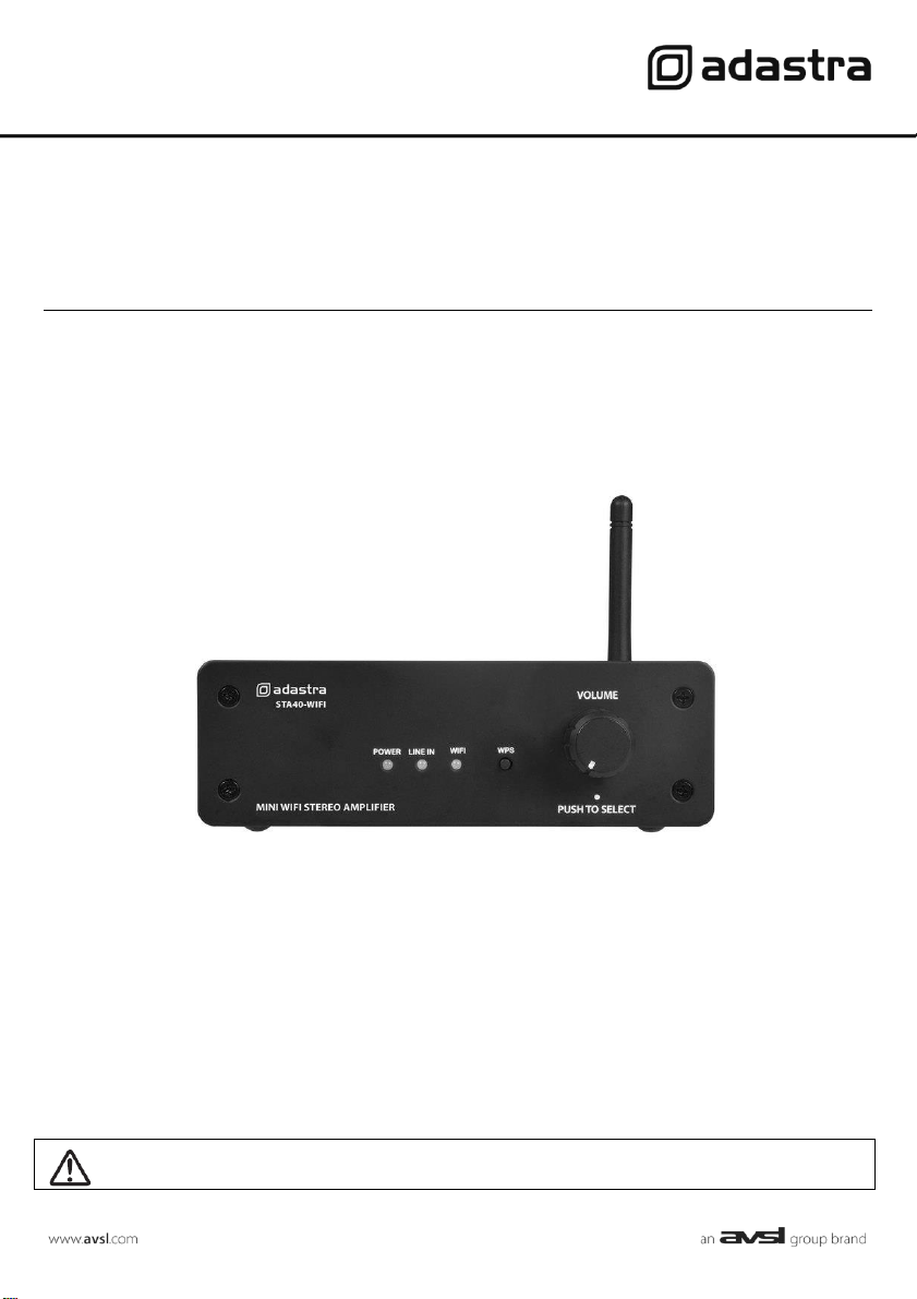
STA40-WIFI
Mini WiFi Streaming Amplifier
Item ref: 103.110UK
User Manual
Version 1.0
Caution: Please read this manual carefully before operating
Damage caused by misuse is not covered by the warranty
Page 2
103.110UK User Manual
Introduction
Thank you for choosing the STA40-WIFI mini WiFi streaming amplifier as part of your
background music system. The wireless connectivity of this product brings together online
audio content and smart phone app control for almost unlimited playback possibilities.
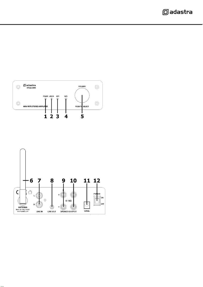
Front panel
Rear panel
1
POWER indicator
2
LINE IN indicator
3
WIFI indicator
4
WPS button
5
VOLUME + SELECT
6
WiFi antenna
7
LINE IN (L+R RCA)
8
LINE OUT (3.5mm stereo jack)
9
Right Speaker output terminals
10
Left Speaker output terminals
11
24Vdc power inlet DC jack
12
POWER on/off switch
Page 3

103.110UK User Manual
Connections and Setting Up
Position the STA40-WIFI on a stable surface within clear reception of the local WiFi signal and where
controls and connections are accessible.
The unit is powered by the supplied in-line 24Vdc power adaptor. With the power switched off, connect
the DC jack of the power adaptor to the rear panel power inlet (11) and connect the mains lead to the
fig.8 socket of the in-line adaptor with the mains plug connected to a suitable mains outlet.
The rear panel WiFi antenna (6) is adjustable but not detachable. Move the antenna so that it points
upwards or outwards from the amplifier for an improved reception.
If a playback device is to be used, connect this to the L+R LINE IN RCA sockets on the rear panel (7).
If the output signal of the amplifier is to be fed onto further equipment, a 3.5mm LINE OUT socket on the
rear panel (8) provides stereo line level output for connecting to the input(s) of additional amplifier(s) or
active speakers.
The STA40-WIFI can power 2 speakers (left + right) with a power handling of 20Wrms each and an
impedance of 8Ω or 16Ω. Note: the STA40-WIFI cannot operate with 4Ω speakers
Connect the L & R SPEAKER OUTPUT binding posts to the left and right speakers by connecting the “+”
to “+” and “-” to “-” for each one, using suitable speaker cable (9, 10)
(0.3mm² CSA or 2.5A rated is recommended)
Operation
When all connections are made, switch the power on to the amplifier and the POWER LED (1) will light.
One of the other 2 source LED indicators will also light. If the illuminated LED is LINE IN (2), the RCA
inputs will be active. If the illuminated LED is WIFI (3), this will flash until WIFI is connected.
Fast flashing = Wifi not connected (searching for WiFi)
Slow flashing = WiFi connected but no app control
Solid light = WiFi connected and app control
If a line input source is available (CD, mp3 player etc.), use this for initial checking.
If only WiFi input is available, it will be necessary to follow the WiFi and App setup later in this manual.
Play a signal into the amp and adjust the output by rotating the VOLUME control (5) left or right.
The output volume can vary from 0 (left) to 100% (right) but the control will continually rotate.
Check the output through each speaker to ensure all input and output signals are working correctly.
To switch between LINE IN and WIFI, push the VOLUME control in briefly.
To reset the STA40-WIFI to factory settings, press and hold the WPS button for 5 seconds.
When both WIFI and LINE IN LEDs are flashing, switch the unit off and on again.
When the STA40-WIFI is powered up again, the unit should be back to factory settings.
Turn down the VOLUME control before powering down to avoid loud noises through the speakers.
Page 4

103.110UK User Manual
Smart Phone & WiFi setup
On your smart phone, download the MUZO Player application.
For iOS devices, download the MUZO Player app from the App Store.
For android devices, download the MUZO Player apk from the Google Play Store.
If your WiFi router has a WPS feature, pressing this and then a short press of the WPS button (4) on the
STA40-WIFI can link the amplifier to your local WiFi network, making setup easier.
Otherwise, follow all steps below to connect your smart phone and STA40-WIFI to the wireless network.
Open the MUZO Player app and the welcome screen will be followed by a “Searching” screen.
If the STA40-WIFI has already been connected to the local WiFi, the Searching screen will confirm that it
has found 1 or more devices. Select this and the app will jump to the “Device List” page.
If the STA40-WIFI is not connected to the local WiFi, select “Add Device”.
The next screen asks for the category of speakers to be added.
For the STA40-WIFI, this is recognized as a MUZO Cobblestone.
Page 5

103.110UK User Manual
Direct WiFi Connection
Select “MUZO Cobblestone” and a further screen will instruct to
search and connect to “LinkPlay_XXXX”
In the case of the STA40-WIFI, the correct ID to search for is
“STA40-WIFI_XXXX” where XXXX is the ID number of the amplifier.
Select “Settings” to go to the smart phone WiFi settings menu.
In the WiFi settings menu, all available WiFi access points within
wireless range will be displayed.
Look for “STA40-WIFI_XXXX” and select it for connection. The
smart phone will release any current WiFi connection and attempt to
connect directly with the STA40-WIFI.
When successfully connected, the WiFi will be without internet
access.
Page 6

103.110UK User Manual
Local WiFi Connection
Select “back” to return from the WiFi settings menu to the MUZO app and the next screen will ask to
connect both the STA40-WIFI and smart phone to the local WiFi network.
Choose the correct local network and enter the password as required and select “Continue”
(note: the WiFi must operate on the standard 2.4GHz band for the STA40-WIFI to join the network)
The STA40-WIFI and smart phone will now begin the connection process.
Page 7

103.110UK User Manual
Device Connected and Naming Device
Once connected, a notification will appear to confirm this, showing the signal strength.
Select “Next” to see the “Name Device” page, which enables the user to give the STA40-WIFI a label to
describe its audio zone.
Select one name (or create a custom name). When this is done, select the “right” arrow at the top of the
screen.
Page 8

103.110UK User Manual
Device List
In the next page, the STA40-WIFI will appear in the Device List.
Several STA40-WIFI amplifiers may be listed with different names if required.
Tapping the ’gear’ symbol opens a settings menu for that specific STA40-WIFI amplifier.
Select one of the devices in the list to go to its main page.
On the STA40-WIFI amplifier’s main page, the current playing track will be displayed with any album art,
a progress bar and playback controls.
Swipe left to go to the Services page, where the playback source can be selected, and the settings can be
adjusted for the STA40-WIFI.
Page 9

103.110UK User Manual
Services
On the Services page, A list of available free and subscription playback sources is shown.
At the top of this page is a Search option to save time when looking for specific program material.
Below this is a Favorites option, where preferred sources or tracks can be selected and stored.
The My Music option enables playback of tracks or playlists stored locally in the smart phone.
Locally stored tracks can be listed by Song, Artist, Album or Folder for convenience.
Selecting the Line In option at the bottom of the Services page remotely switches the STA40-WIFI to play
back from the rear panel RCA line inputs.
Some of the listed services require a subscription and may be added or removed from the list as required.
For internet radio services, TuneIn and iHeart Radio (U.S. only) are included.
Selecting the TuneIn service is described on the following page.
Page 10

103.110UK User Manual
TuneIn
TuneIn is a free-to-use app with optional paid versions for premium features.
Using this service allows the user to browse any online radio station listed by locality or genre.
Selecting a radio station sets playback to stream directly from the internet to the STA40-WIFI amplifier.
Once streaming is initiated, connection to the smart phone is not needed except for further control.
When the smart phone or other sending device is disconnected from the local WiFi, the STA40-WIFI will
continue to stream the audio file(s), playlist, podcast or internet radio station that is currently playing.
To change the audio stream or output level remotely, it is necessary to connect the smart phone to the
local WiFi and open the Muzo Player app for control.
When the STA40-WIFI is powered down, the audio stream needs to be re-set when powered on again.
Disposal: The “Crossed Wheelie Bin” symbol on the product means that the product is classed as
Electrical or Electronic equipment and should not be disposed with other household or commercial waste
at the end of its useful life. The goods must be disposed of according to your local council guidelines.
Errors and omissions excepted. Copyright© 2020. AVSL Group Ltd.
Unit 2-4 Bridgewater Park, Taylor Rd. Manchester M41 7JQ
 Loading...