

Page 1
DIGITAL INDOOR TV ANTENNA
120.727
INT RODUC TION:
This is a special designed antenna for both analogue and digital terrestrial TV broadcasting
reception. It can receive all the TV signals of your area in VHF and UHF band, as well as the FM radio
signal. It is the best solution for home reception and digital portable TV reception.This antenna is an
active antenna powered through AC power. It is very practical to install and very easy to use.
Technical Data:
Frequency range: VHF:87.5-230MHz UHF:470-862MHz
Receiving Range: FM/VHF/UHF
Max Gain: VHF:20dB; UHF:25dB
Output Level: 95dBµV Max
Out Impedance: 75Ω
Noise Figure: ≤5dB
Power Supply: AC230V
Pro duct Fe ature s:
Variable gain control
Power On/Off LED indicators
SMD circuit technology design
Built-in high gain and low noise amplifier.
Adjustable loop aerial for the best UHF reception
Adjustable Telescopic antennas for optimum VHF and FM radio reception
Specially designed for HDTV of various digital terrestrial signal (DVB-T, ISDB-T, DMB-T/H, ATSC)
and DAB/FM radios.
INS TALLATI ON:
Note:For the best reception,Please check the following conditions
1. Keep the antenna away from the sources of interference: keep the antenna away from those
big power consumption devices,such as air conditioner,elevator,hair dryer and microwave
oven...ect.
2. Place the antenna near windows when use the antenna in indoor environment.
3. Install the antenna as high as possible: in digital terrestrital reception,if there are some
interceptions between antenna and transmission tower,it will cause the signal loss temporary. So
if the antenna is installed high as possible, those interceptions will be reduced.
UHF reflector
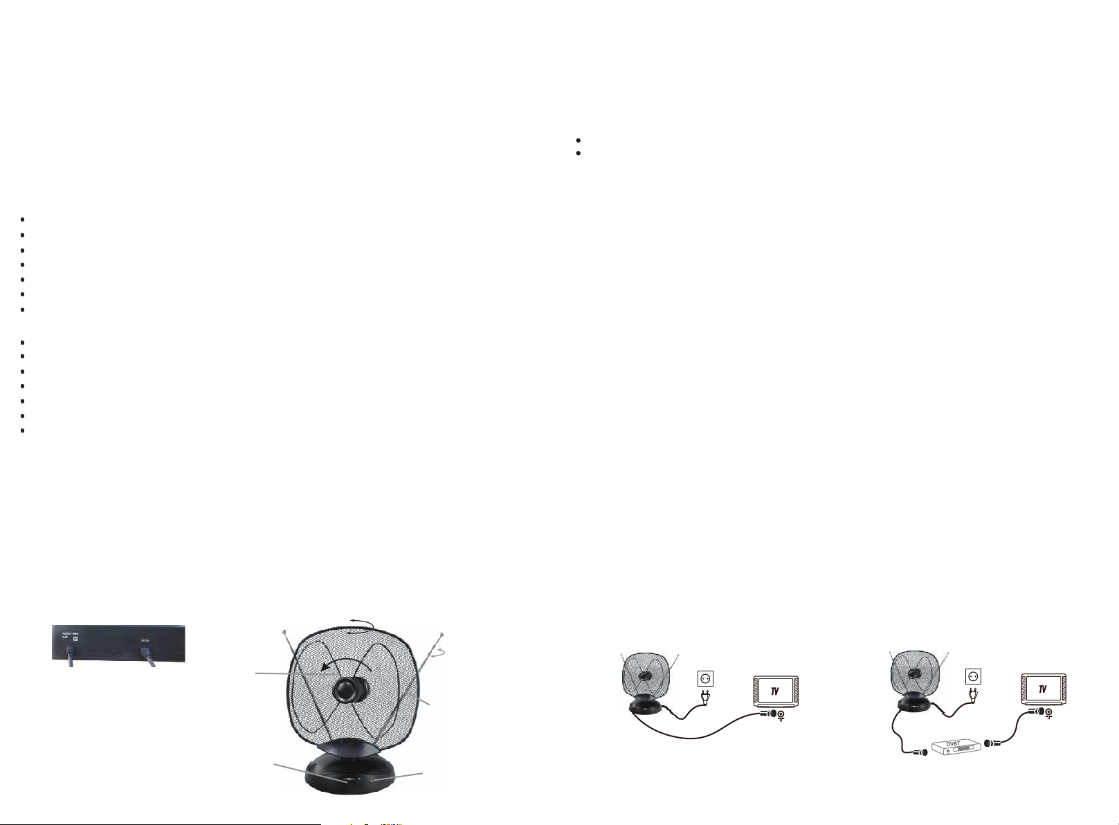
(1) (2)
Power Plug
Signal output
(5)
Tilt UHF dipole for
receiving
Channels 21-69
Can be turned
anticlockwise direction
0
(within 90 )
(6)
Can be turned sideways (within 90 )
0
Can be turned 360
(7)
VHF Telescopic Antenna,
for receiving channels 1~12
0
SETTING AND CONNECTIONS
Connect the AC 230V~ cable (1) to the 230V AC wall socket.
Connect the TO TV cable (2) to the antenna-input socket of your TV or terrestrial digital set-top box.
After checking that all the connections have been done properly, turn on the power switch (4) to
switch the antenna on: led (3) lights up showing that the amplifier of indoor antenna is working. Now,
turn your television set on and select a TV programme, then adjust the rod antennas (7), the UHF
dipole (6), the UHF reflector(6) and the amplifier gain adjuster knob (4) according to what is
described in next paragraphs.
SIG NAL REC EPTIO N
VHF SIGNALS - I-III BAND (channels 1-12)
This antenna receives VHF signals (both analogue and digital) through the rod antennas (7).
For best reception, adjust rod antennas as follows:
- for I Band: extend completely the rod antennas;
- for III Band: shorten the rod antennas to about 16 inches (the extension depends on the
channel you want to receive);
- then, move the rod antennas until you get the best signal reception.
UHF SIGNALS - IV-V BAND (channels 21-69)
This antenna receives UHF signals through dipole antenna (5):
- turn the UHF reflector sideways;
- turn the UHF dipole in anticlockwise direction until you get the best signal reception.
GAI N ADJUS TING
In order to adjust the amplifier gain turn gain adjuster knob (4) until to get the best signal reception:
- to increase gain, turn the knob clockwise
- to reduce gain, turn the knob anticlockwise
Note: This antenna can be used directly connected to TV or terrestrial set-top box, please take
reference of following 2 different connecting ways to instal your antenna.
(Fig.1), Directly connec ted to T V
(Fig.2), Directly conne cted to terrestrial set-top box
Fig .1
AC 110V/220V
Fig .2
AC 110V/220V
(4)
Gain Adjustment knob
(3)
Power indicator light
 Loading...