

Page 1
Curtarolo (Padova) Italy
www.avselectronics.com
VECTOR Plus
Bidirectional
INTERFACE
INSTALLATION MANUAL
IST0401V2/1
QUALITY
SYSTEM
ISO9001
Page 2

11 sms list ...................................................................
11telephone numbers on mobile phonebook ................................
10dialler programming to send "by command" sms messages ...............
9parameters programming (sms by command) .............................
8parameters programming (automatic sms) ................................
8sms functions .............................................................
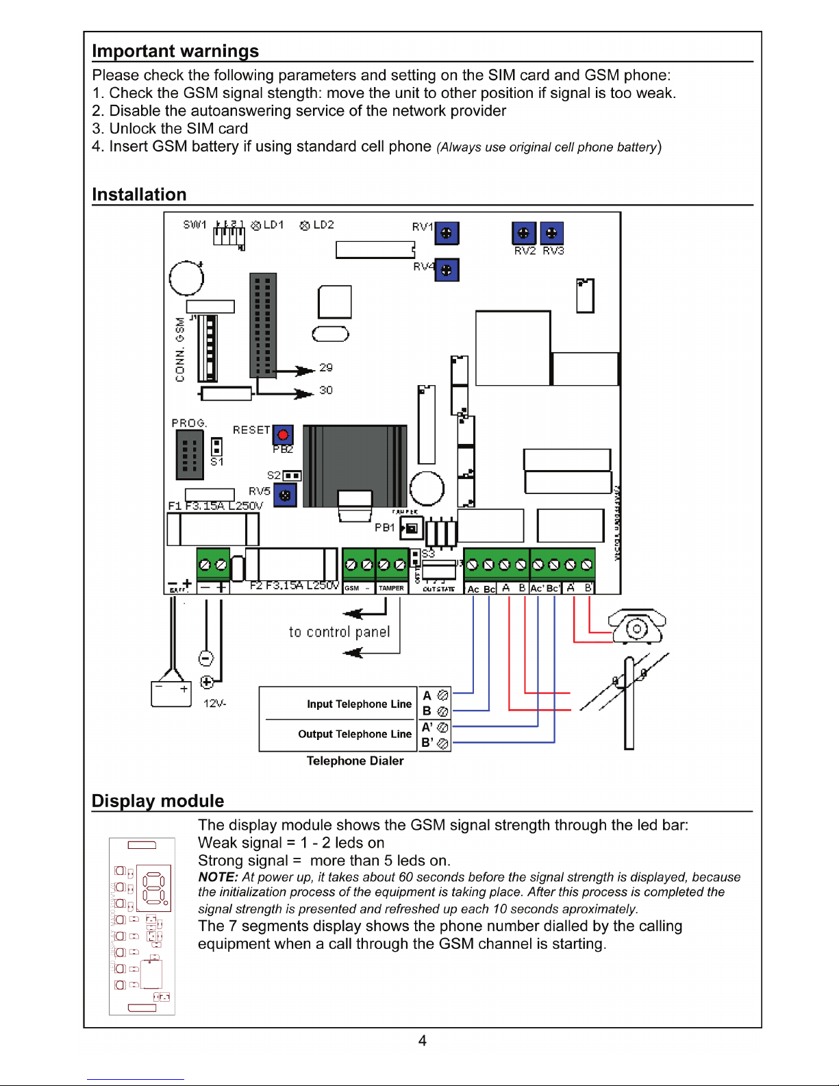
7display module connection ................................................
7plugging in sim card / antenna jack ........................................
7gsm engine connection ...................................................
6settings ...................................................................
6input and output ...........................................................
6leds .......................................................................
6dip switches ...............................................................
5
j
umpers and trimmers .....................................................
5testing vector plus .........................................................
5other display indications ...................................................
4display module ............................................................
4installation ................................................................
4important warnings ........................................................
3gsm compatibilities (see technical updates sheet) .........................
3technical characteristics ...................................................
3operation ..................................................................
3features ...................................................................
2
Page 3
Features
The VECTOR Plus GSM interface is used, toghether with an approved telephone set or dialler,
to send and receive telephone calls through the GSM network, when PSTN line is missing.
The interface continuously monitors the PSTN line; when a fault condition is detected VECTOR
Plus switches the telephone equipment connected to its terminals to an internal telephone line
simulation circuit, able to manage calling procedures eventually started by the telephone
equipment, including dial tone and busy tone generation, dialling sequence recognition and
ringng signal generation. Thus VECTOR Plus can be used in a bidirectional way: to send
and/or receive GSM telephone calls.
Additionally, VECTOR Plus can send technical and alarm SMS messages to a maximum of 50
telephone numbers.
VECTOR Plus has also the possibility to send a periodic SMS message (autotest) within a
programmable time interval.
Operation
In normal installations, VECTOR Plus is connected to PSTN line, to alarm telephone dialler and
to telephone handsets of the premise. When the PSTN line voltage (normally 48V) goes below
about 35V, VECTOR Plus starts monitoring the line looking for the dial tone frequency (425Hz
typical). If that signal is not detected within 30 seconds, the interface switches automaticly to
"GSM mode", bringing the alarm dialler to the internal telephone line simulation circuit, whereas
the telephone sets are bypassed directly to the PSTN line.
In this condition, if the dialler attempts to execute a telephone call, VECTOR Plus generates the
dial tone signal like the normal telephone line, and waits the dialling sequence from the external
device (only DTMF dialling is accepted). After the dialling sequence is completed the call is
routed through the GSM unit and VECTOR Plus generates the ringing tone and/or busy tone.
Once the GSM connection is established the voice channel stays open allowing data and voice
signals transfer between the dialler and the called party. At the end of the call, as the dialler
realeases the simulated PSTN line, the GSM connection is interrupted. When terminal "GSM -"
is open, VECTOR Plus waits 60 seconds, after a call through the GSM channel, before
switching back to "PSTN line mode" (normal mode), provided that PSTN line voltage has
returned to its normal value (aprox. 48V).
When the "GSM" terminal is closed to negative or in case of permanent fault of PSTN line,
VECTOR Plus interface allows receiving calls through the GSM channel, since, when an
incoming call is detected by the GSM unit, a valid RING signal is generated at the simulated line
terminals of VECTOR Plus, causing the ring detector of the dialler or the ringing bell of a
telephone to be activated.
Technical characteristics
Power supply voltage: 12V=
Supply voltage tolerance: 11.5 - 15 V=
Current consumption: 300 mA / max 500 mA
(when charging GSM battery, if any)
Recommended backup battery: 12V / 1.2 Ah
Dialling mode supported: multifrequency (DTMF)
Dial tone: 425Hz continuous or cadenced (for Italy)
Busy Tone: (425Hz) pulsed
Transmission Protocols supported:
ID CONTACT, FAST, SLOW, SEIA, SIA, VOCAL and half duplex protocols (FAX and MODEM like
protocols are NOT supported)
Dimensions (h x l x w) (mm): 225 x 210 x 80
GSM compatibilities (See technical updates sheet)
3
Page 4
Page 5

Other display indications
As stated before, at power up an initialization procedure of about 1 minute takes place, during
which the equipment configures itself according to programming parameters stored in the SIM
card. The 7-segments display shows some default characters to indicate the advancement of
this process:
at the beginning, a line shifts on the display from bottom to top. Then an A character flashes
for about 30 - 40 seconds. Finally, a C character shows till the end of the initialization, when the
led bar will start to indicate the signal strength.
Additional messages on the display:
: An horizontal line shifting from bottom to top is displayed when sending an SMS message.
C : The C character is displayed when executing the periodic autotest with SMS sending.
F (flashing) : This character indicates PSTN line fault condition.
8 (blinking) : Indicates an incoming call through the GSM.
Trouble and Fault messages:
0 = VECTOR Plus is not able to turn on the GSM unit.
1 = Wrong or missing serial comunication between VECTOR Plus and GSM unit.
2 = Wrong PIN security code on the SIM card.
(correct value 0000)
3 = No GSM service available
4 = Poor signal level
5 = Battery problem (only when using standard cell phone)
6 = Unknown general problem
Testing VECTOR Plus
In order to verify the efficiency and the signal quality of the GSM channel, we suggest the
following test: connect a normal telephone set to terminals Ac - Bc of the interface and close to
negative the terminal "GSM". Power up the unit and wait the initialization process is completed
(see display). Execute some telephone calls and evaluate the signal and audio quality of the GSM
connection.
Jumpers and trimmers
Jumper S1: closed if using Siemens cell phones - open if using industrial GSM engine
Jumper S2: open if using Siemens cell phones - closed if using industrial GSM engine
Jumper S3: (OFF - TT) closed disables the tamper switch
RV5: serves to adjust the GSM unit voltage - 3,85V for industrial GSM engine - 8,5V for
Siemens cel phones. (WARNING: Avoid mounting the industrial GSM engine if voltage is adjusted for
Siemens cell phones, because it will cause permanent damage of the GSM module)
RV2: adjusts the audio level of the signal received from the GSM unit.
RV3: adjusts the audio level of the signal applied to the GSM unit for transmission.
(NOTE: RV2 and RV3 are factory adjusted to recommended values. Therefore additional adjustment
normally is not needed)
PB1: Tamper switch connected to the TT terminals.
PB2: Microprocessor reset switch.
5
Page 6

Dip switches
Dial tone
continuous tone (other european countries)
DIP 1 in ON
cadenced tone (for Italy)
DIP 1 in OFF
PSTN line fault detection procedure
PSTN line voltage monitoring + PSTN line activity monitoring (PSTN line dial
tone signal is NOT supervised)
DIP 2 in ON
PSTN line voltage monitoring + PSTN line valid dial tone monitoring +
PSTN line activity monitoring (no activity for 60 seconds = fault)
DIP 2 in OFF
PABX connection
If VECTOR Plus interface were to be installed in premises where PABX equipment is present,
requiring additional digits when dialling to reach external telephone line (Ex. 0 or 9):
connection through PABX: the interface eliminates the first digit of
telephone number when dialling through the GSM.
DIP 3 in ON
direct connection to external telephone line
DIP 3 in OFF
Important
always ONDIP 4 in ON
Factory defaults
DIP 4 ONDIP 3 OFFDIP 2 OFFDIP 1 OFF
LEDs
LD1: shows the GSM module operation status: flashing - GSM module is registered in the
network and in stand-by; on - a GSM call is taking place; off - the GSM module is NOT correctly
registered in the network (failure condition)
LD2: must be always ON indicating that the GSM module is working.
(NOTE: this two leds will activate only when using the industrial GSM module)
Input and output
"GSM" input: when connected to negative forces the operation in GSM mode, for installations
where PSTN line is not available. All PSTN line monitoring functions are disabled.
TT output
: Tamper output to be connected to a 24 hous loop of the control panel.
OC1
output: open collector output activated when PSTN line fault is detected.
OC2 output: open collactor output activated when GSM failure is detected.
OC3 output: not used
Settings
RV3 (Adjust only if needed) It is used to adjust the frequency of the telephone line signals generated
by VECTOR Plus (dial tone and busy tone = typical 425Hz) in the case the dialler connected to it were
to have some difficulties in recognizing them.
6
Page 7

GSM engine connection
S1
F1 F3.15A L250V
C
O
N
N
.
G
S
M
PROG.
BATT.
SW1
T
TAMPER
TAMPER
S2
F2 F3.15A L250V
RV5
GSM
T
PB1
RESET
PB2
CENTR.
Bc
3
OUT STATE
O
F
F
T
T
21
S3
Ac
A B
Bc
CENTR.
Ac
A
RV4
RV2 RV3
RV1
V
E
C
T
O
R
M
A
0
0
3
3
3
V
3
/
2
B
odulo
SM
Connect the GSM engine to 30 pin female connector.
Plugging in sim card / antenna jack
GSM engine with upper side SIM Card holder:
1. Press pushbutton A.
2. Extract B holder.
3. Put SIM card on B.
4. Insert B holder all the way long into its receptacle.
GSM engine with right side SIM Card holder:
To insert SIM Card:
1. Insert SIM Card completely into slot C until it clicks inside
the module
To remove SIM Card:
1. Press and release the SIM Card to cause it to be ejected
through the slot.
Antenna jack:
Place the male connector of the antenna
cable into the female one of the module
and apply slight pressure in the axis
direction to click it into the module. Do not
force or bend the cable sideway. To
remove the cable, hold the connector with
the fingertips and pull avoiding bending it
sideway. Do not pull the cable.
Display module connection
Remove power from the interface and
insert the display module into the proper
connectors as indicated in the figure.
7
GSM engine
A
B
C
Ingresso connettore antenna
Input antenna jack
Page 8

SMS functions
The phone numbers to which SMS messages are going to be sent and the SMS messages
text, must be stored into the SIM card. To execute this operation use a normal cell phone.
Before programming the SIM card, please erase completely the existing contents that could be
stored into it. Note that the first three (3) SMS messages stored into the SIM card are used for
technical purposes, and are sent automaticly by VECTOR Plus when the respective monitoring
functions are enabled. This messages are:
SMS nr. 1: PSTN line fault.
SMS nr. 2: PSTN line restore
SMS nr. 3: Autotest
NOTE: if one or more of the above technical messages is NOT required, it is possible to store a different
message in the corresponding SIM card space to be sent "by command" as will be described in the
following chapters.
To enable/disable the functions that send technical SMS messages automaticly, two special
numbers must be stored into the SIM card phonebook, that are used to configure the system.
This two numbers has to be associated to the names "1" and "2"
(instead of "Smith" or "Johnson").
The digits included in the number under name "1" determine wheather the three types of
technical SMS messages are to be sent or not, and wheather the technical messages are to be
sent to all the telephone numbers present in the phonebook
(max. 50) or only to the first one. The
number stored under name "2" indicates the autotest repetition intervall (in hours: from 0 to 255).
All the telephone numbers to which the SMS messages will be sent must be stored into the SIM
card phone book, keeping in mind that the first number stored has a priority over the rest of the
numbers, because it is the one which technical SMS messages are sent to by default, otherwise
differently specified in configuration parameter "1".
Apart from the technical SMS, that are automaticly sent by VECTOR Plus once they has been
enabled through the configuration numbers, the remaining SMS stored into the SIM card by the
installer to communicate any kind of alarm or status information, can be sent through the
VECTOR Plus interface only in "by command" mode, issuing special DTMF sequences at
terminals Ac - Bc like executing a normal telephone call. Note that, for alarm or status SMS
messages to be sent, it is necessary that VECTOR Plus interface is operating in "GSM mode",
therefore, it is suggested to use an output from the telephone dialler or control panel to force
VECTOR Plus into GSM mode through terminal "GSM", before issuing the proper DTMF
sequence to send the SMS. This is not necessary if the equipment is already functionning in
permanent GSM mode, with terminal "GSM" always connected to negative.
Parameters programming (automatic SMS)
SIM card phonebook .Parameter "1": the values stored under this name into the phonebook determine wheather
technical SMS messges must be sent or not.
Including the digit 1 in the number enables sending the "PSTN line fault" SMS messages.
Including the digit 2 in the number enables sending the "PSTN line restore" SMS message.
Including the digit 3 in the number enables sending the "Autotest" SMS message.
Including the digit 8 in the number, technical SMS messages are sent to all telephone numbers
present in the phonebook
(max. 50), otherwise they are sent only to the first telephone number of
the phonebook.
Parameter "2": the value stored under this name into the phonebook represents the repetition
intervall
(in hours), of the autotest SMS message. This value should be between 0 and 255.
8
Page 9

Example:
Name: ”1”
Number: 138
Nome: “2”
Numero: 12
Parameters programming (SMS by command)
It is possible to send SMS messages stored into the SIM card using a standard touchtone
telephone set connected to terminals Ac - Bc. If the PSTN line is present, to send SMS
messages "by command", it is necessary to close to negative by a few seconds the terminal
"GSM" of the unit, to force it into GSM mode. In contrast, if the PSTN line is not available,
VECTOR Plus is supposed to be already operating in GSM mode.
Sending an SMS message "by command" is like dialling a normal telephone number. The
sequence of DTMF digits to be sent is the following: 0000nnTT, where;
0000: is a prefix that informs VECTOR Plus that the sequence is not a normal telephone call but
an SMS message request. (NOTE: although VECTOR Plus were connected through an internal PABX
and were configured with DIP3 in ON position, which causes elimination of the first digit of the number
when calling through GSM, IT IS NOT NECESSARY TO ADD A"0" digit to the prefix to activate SMS
function. The prefix must always be 0000)
nn: is the number corresponding to the SMS message that has to be sent, and depends on the
order messages were stored into the SIM card when programmed. Remember that, as explained
before in this document, the first three SMS messages are used for specific technical
communications and their content shall be wrote according to their function, however, if some of
this technical messages are not required, they can be filled up with a different text to be sent "by
command" when needed.
TT: is the position into the SIM card phonebook of the telephone number to which the SMS
message has to be sent. Like for the text messages, the position of telephone numbers also
depends on the order they were stored into the SIM card when programmed. Issuing "99" as the
value of TT, the selected SMS message will be sent to all telephone numbers (max. 50) contained
in the SIM card phonebook.
Example 1:
Dialling: 00000712
VECTOR Plus will send the SMS message stored in position 7 of the SIM card to the telephone
number stored in position 12 of the internal phonebook.
Example 2:
Dialling: 00000599
VECTOR Plus will send the SMS message stored in position 5 of the SIM card to all telephone
numbers in the phonebook.
NOTE 1: to enable sending an SMS by command when VECTOR Plus is not operating in GSM mode, simply
shortcircuit to negative for a few seconds the "GSM" terminal of the equipment, while dialling the DTMF
sequence for SMS activation. Once the SMS message has been sent, the operation will return to normal
mode and successive telephone calls will go on over PSTN line.
NOTE 2: after issuing the SMS activation sequence, the dialling equipment must wait the initiation of SMS
sending procedure, indicated by a "shifting line" in the display (see Display indications chapter), before
releasing the simulated line at Ac - Bc terminals, otherwise, the SMS procedure is aborted.
9
SMS 1 “PSTN line fault” is enabled. - (1)
SMS 2 “PSTN line restore” is disabled.
SMS 3 ”Autotest” is enabled. - (3)
The technical SMS messages enabled will be sent to all telephone
numbers stored into the SIM card phonebook - (8)
Autotest SMS will be sent every 12 hours. - (12)
Page 10

Dialler programming to send "by command" SMS messages
To make a telephone dialler connected to VECTOR Plus activate SMS messages "by
command", the following steps are required:
1: program one of the telephone numbers of the dialler with the proper digits sequence
(0000nnTT) as explained hereon.
2: associate to that telephone number some default communication protocol.
3: program the dialler to make one single calling attempt to that telephone number. If there are
repetitions, the SMS message will be sent many times.
4: program an output from the dialler or control panel to activate by a few seconds bringing to
negative "-" the "GSM" input terminal of the interface, while the telephone number is being
dialled.
NOTE 1: using AVS ELECTRONICS diallers or control panels, setting to "0" the number of attempts of
telephone calls will cause the dialler to make one single calling attempt.
NOTE 2: if the telephone number for SMS activation is not the first number "called" by the dialler, once the
"GSM" input terminal of VECTOR Plus has received the pulse to negative, all telephone calls previous to
the SMS activation number will be executed through the GSM channel, while successive ones will occur
over PSTN line.
Example:
Tel. numb 1: alarm telephone call
Tel. numb 2: alarm telephone call
Tel. numb 3: alarm telephone call
Tel. numb 4: SMS activation command
Tel. numb 5: alarm telephone call
Tel. numb 6: alarm telephone call
xxPSTN line
x
xxxGSM
Call to #6Call to #5
SMS cmd #4
Call to #3Call to #2Call to #1
10
Page 11

Telephone numbers on mobile phonebook
SMS list
11
25
24
23
22
21
20
19
18
17
16
15
14
13
12
11
10
9
8
7
6
5
4
3
2
1
Telephone numberName
saved
Posit.on
M.add.
50
49
48
47
46
45
44
43
42
41
40
39
38
37
36
35
34
33
32
31
30
29
28
27
26
Telephone numberName
saved
Posit on
M.add.
14
13
12
11
10
9
8
7
6
5
4
3 tecn.
2 tecn.
1 tecn.
SMS DescriptionN.
SMS
28
27
26
25
24
23
22
21
20
19
18
17
16
15
SMS DescriptionN.
SMS
Page 12

AVS ELECTRONICS S.p.A.
Via Valsugana, 63
35010 (Padova) ITALY
Tel. 049 96 98 411
Fax. 049 96 98 407
avs@avselectronics.com
www.avselectronics.com
AVS ELECTRONICS S.p.A. reserves the right to modify the technical and esthetical characteristic of the products at
any time.
 Loading...