

AVS Electronics CAPTURE, CAPTURE 8, CAPTURE 32, CAPTURE 16 Installation And Programming Manual
Page 1

Curtarolo (Padova) Italy
Codice: BOZZA 1057
Data: 30/07/2014 Formato: 50x70 mm
Tipo di carta:
PATI NATA
Adesivo:
P.
Plasticazione:
/
Verniciatura:
/
Stampa a caldo:
/
DATI ROTOLO
Pezzi bobina:
/
Anima interna:
/
www.avselectronics.com
GENERAL INSTALLATION
AND
PROGRAMMING MANUAL
CAPTURE
CERTIFIED
QUALITY SYSTEM
UNI EN ISO 9001:2008
IST0865V1.0
- 1 -
Certied products
IMQ - Security Systems
EN 50136-2-1
EN 50131-1
EN 50131-3
EN 50131-6
CEB T014
Page 2

Indice
GENERAL INFORMATION ........................................................................................................................................................................... pag. 3
CAPTURE 32 - Technical features ................................................................................................................................................................ pag. 4
CAPTURE 16 - Technical features ................................................................................................................................................................ pag. 5
CAPTURE 8 - Technical features .................................................................................................................................................................. pag. 6
Type of connections ...................................................................................................................................................................................... pag. 12
Control panel board CAPTURE 32, CAPTURE 16, CAPTURE 8 ................................................................................................................. pag. 14
Terminal board, Jumper and Connectors CAPTURE 32, CAPTURE 16, CAPTURE 8 ................................................................................ pag. 14
Supply unit section ........................................................................................................................................................................................ pag. 15
Connections module XGSM and module EWEB WIFI .................................................................................................................................. pag. 15
Keyboard A500 - A500 Plus ......................................................................................................................................................................... pag. 16
Satellites ........................................................................................................................................................................................................ pag. 18
Hints on armings management ..................................................................................................................................................................... pag. 19
PSTN Telephone - Technical features ........................................................................................................................................................... pag. 20
DIGIVOC (optional) - Technical features ....................................................................................................................................................... pag. 20
PSTN + GSM ............................................................................................................................................................................................... pag. 20
XGSM - Technical features............................................................................................................................................................................ pag. 21
SIM Card Inclusion/Antenna Connector Input ............................................................................................................................................... pag. 21
XGSM485 - XGSM485 PRO - Technical features ......................................................................................................................................... pag. 22
Checking Credit and Expiry of the SIM Card for XGSM - XGSM485 and XGSM485PRO ........................................................................... pag. 24
Recording of vocal messages ....................................................................................................................................................................... pag. 24
Recording with XWIN software procedure XWIN (CAPTURE e DIGIVOC): ............................................................................................ pag. 24
Vocal messages ............................................................................................................................................................................................ pag. 25
Telephone Table - 1st .................................................................................................................................................................................... pag. 26
Telephone Table - 2st .................................................................................................................................................................................... pag. 27
Telephone Table - recorded messages ......................................................................................................................................................... pag. 27
RTC ACTIVATION BY A CALL FROM THE CONTROL PANEL .................................................................................................................... pag. 28
USER RTC ACTIVATION .............................................................................................................................................................................. pag. 28
DTMF Commands ................................................................................................................................................................................... pag. 28
RTC USER with recognition of incoming number ......................................................................................................................................... pag. 28
INSTALLER RTC ACTIVATION ..................................................................................................................................................................... pag. 28
Outgoing SMS Management ......................................................................................................................................................................... pag. 29
Incoming SMS Management ......................................................................................................................................................................... pag. 29
Programming ................................................................................................................................................................................................. pag. 30
Hints on sectors management ................................................................................................................................................................. pag. 30
Manufacturers Declaration of Conformity R&TTE 99/05/CE ......................................................................................................................... pag. 70
- 2 -
Page 3

GENERAL INFORMATION
The control panels Capture are compatible with the following devices
ARTICLES DESCRIPTION
CAPTURE 32 Microprocessor central control unit
CAPTURE 16 Microprocessor central control unit
CAPTURE 8 Microprocessor central control unit
A500 Operating keyboard
A500 Plus Operating keyboard
TOY L, TOY T Proximity key with “NFC” technology
TOY C Proximity badge with “NFC” technology
XGSM GSM telephone communicator
XGSM485 - XGS485PRO GSM telephone communicator
DIGIVOC Voice synthesis boards
XEXP8 Zone expansion module
XSATWS Zone expansion module via radio
C8 Zone and output expansion module
XSAT36 Zone and output expansion module
XSATHP Expansion module for digital sensors
XSATPW 3 Power feeder in boards with zone and output expansion
XSATPW 3 Q Power feeder in metallic box with zone and output expansion
XSATPW 5 Power feeder in boards with zone and output expansion
XSATPW 5 Q Power feeder in metallic box with zone and output expansion
POWER 3 Extra power feeder in board
POWER 3 Q Extra power feeder in metallic box
POWER 5 Extra power feeder in board
POWER 5 Q Extra power feeder in metallic box
XMR2 2-relay board
MR4 4-relay board
MR8 8-relay board
EWEB LAN - WEB SERVER interface
EWEB WIFI LAN - WEB SERVER WIFI interface
P
P
P
P
P
P
P
P
P
P
P
P
P
P
P
Grado 3
Grado 2
Grado 3
Grado 3
Grado 3
Grado 2
Grado 3
Grado 3
Grado 2
Grado 2
Grado 2
Grado 2
Grado 3
Grado 3
Grado 3
La conformità alla normativa EN50131 decade se:
• i dispositivi non vengono installati nei contenitori CONT-CAPTURE, CONT SX e CONT SAT W o facendo riferimento a quanto
espressamente indicato nella tabella.
The products must be used according to the intended use and in compliance with the rules applicable to the various plant engineering
types.
However, before commissioning the installed products, the system must be tested in order to verify its functioning and compliance
with the safety rules according to that indicated by Law n. 46 dated 05/03/90 and by Standard CEI 79-3.
The equipment must not be exposed to dripping or water sprays and no object full of liquid must be placed on it.
INSTALLATION AND MAINTENANCE MUST BE EXECUTED BY QUALIFIED PERSONNEL
AVS ELECTRONICS S.p.a. reserves the right to make amendments at any moment and without notice.
- 3 -
Page 4

CAPTURE 32 - Technical features
Microprocessor control panel that manages all functions typical of a safety and protection system, in that it is able to discriminate the signals coming
from burglar proof , re protection, anti-robbery, medical assistance, etc detectors.
The system is made of a control panel and of at least one keypad of (mod.A 500-A500Plus) type and it can be completed with extension satellite electronic boards of (mod.C8, XSAT36, XSATPW 3, XSATPW 5, XSAT WS, XSATHP, XSATHP Virtuale) type, with network adapter (mod.
EWEB, EWEB WIFI), with GSM dialler (mod.XGSM e/o XGSM485) and the vocal synthesizer (DIGIVOC); the PSTN dialler is already included
in the control panel electronic board.
Keypads • maximum n. 8 with display (mod.A500 - A500Plus), on 600 total meters of cable with 4 wires per serial
Serial sirens • max n° 8 (mod. CITY LED HP, CITY X HP, CITY CARBON HP, TS85 P LED HP, TS85 V LED HP, TS85 X LED HP)
Satellites • max n° 8 (mod. C8, XSAT36 , XSATPW 3, XSATPW 5, XSAT WS, XSATHP o Virtual XSATHP)
Chiavi seriali • n° 32 lettori seriali (mod. RS)
Software zones • n° 32, programmable with automatic detection of the state of alarm and of tamper proof, individually mana-
Input zones ••n° 8 expandable at 171
Sectors • n° 8 (separate sectors)
Zones conguration • Immediate, Conditional, Immediate with permanent exclusion, Immediate with temporary exclusion, Timed, Ti-
Zone options • Impulses, alarm memory and reset, N.C. connection, N.A. connection, End of line 1R, End of line 2R (tamper
Events memory • n° 512 events can be memorised with date and time and outcome of the calls
Alarm outputs ••n° 1 alarm relay programmable with 2-ways and output. Connect only circuits working with SELV voltage to
Armings ••n° 4 automatic arming modality
Codes •
Timer •
Telephone •
Check on power supplies • signal on display of the control panel functioning anomalies or supervised additional supply units
Programming •
Voltage • stabilised power supply nominal voltage: 13.8 V =
Sizes ••keypad A500 - A500 Plus (LxHxP): 135 x 114 x 35 mm
Environmental conditions • Temperature -10 °C / + 55 °C - Humidity 95%
Environmental class • Class II
Weight without battery • 5 Kg
Max. current absorbed • 135 mA / 230 V ~
Max. current absorbed on
13.8V =
Placeable battery • 7 Ah
IMQ Performances •
Zones in keypad: n° 2
geable.
n° 1 input dedicated to tamper proof, cannot be excluded.
med with temporary exclusion 1, Timed with permanent exclusion 1, Arming ON, HOME, ZONE, PERIMETER,
24 hour line, Timed 24 hour line 1, Tamper line, Not used
signal), chime function, door, zones under test, buzzer in alarm, activates O.C. outputs, AND zones and AND
directional, radio supervision management, 16 digits alphanumerical stripe, Alarms Coding, Vibration sensor,
Shutters switch.
these outputs.
n° 7 (max 32) transistorised outputs (50 mA-OpenCollector) on terminal boards for connection with relay
electronic boards (mod. MR4 / MR8) upon request. Congurable in various modalities..
From display keypad or from outdoor activations in it ON, HOME, AREA and PERIMETER modality
n° 128 user codes available from 4 to 6 digits
•
n° 8 programmable user proles
•
n° 128 automatic Emergency codes (with more than 1.000.000 combinations)
16 daily operations for all sectors
•
armings/disarmings of sectors and OC activation
•
“copy copy from Monday to Friday” and “copy from Monday to Sunday” functionca
•
10 programmable holiday periods
•
automatic summer time-standard time and standard time-summer time change
•
duration Inclusion Warning/Extraordinary management
•
inhibition of the codes with Timer armed
n°16 telephone numbers on PSTN/GSM line
•
n°40 customisable vocal messages as well as extended vocabula
•
GSM telephone dialler GSM (mod. XGSM e/o mod. XGSM 485) optional
(mod. XSATPW 3, XSATPW 5, POWER3, POWER5)
from display keypad with simplied guided menu
•
from PC in direct connection with software Xwin and USB cable
•
from PC connected via telephone with software Xwin and universal modem
•
from PC connected via network with software Xwin
housing (LxHxP): 330 x 420 x 107 mm
• only 130 mA control panel electronic board with PSTN telephone dialler activated
EN 50131- 1 Grado 3 • EN50136-2-1
•
EN 50131- 3 Grado 3
•
EN 50131- 6 Grado 3
- 4 -
Page 5

CAPTURE 16 - Technical features
Microprocessor control panel that manages all functions typical of a safety and protection system, in that it is able to discriminate the signals coming
from burglar proof , re protection, anti-robbery, medical assistance, etc detectors.
The system is made of a control panel and of at least one keypad of (mod.A 500-A500Plus) type and it can be completed with extension satellite electronic boards of (mod.C8, XSAT36, XSATPW 3, XSATPW 5, XSAT WS, XSATHP, XSATHP Virtuale) type, with network adapter (mod.
EWEB, EWEB WIFI), with GSM dialler (mod.XGSM e/o XGSM485) and the vocal synthesizer (DIGIVOC); the PSTN dialler is already included
in the control panel electronic board.
Keypads • maximum n. 8 with display (mod.A500 - A500Plus), on 600 total meters of cable with 4 wires per serial
Serial sirens • max n° 4 (mod. CITY LED HP, CITY X HP, CITY CARBON HP, TS85 P LED HP, TS85 V LED HP, TS85 X LED HP)
Satellites • max n° 4 (mod. C8, XSAT36 , XSATPW 3, XSATPW 5, XSAT WS, XSATHP o Virtual XSATHP)
Chiavi seriali • n° 32 lettori seriali (mod. RS)
Software zones • n° 16, programmable with automatic detection of the state of alarm and of tamper proof, individually mana-
Input zones ••n° 8 expandable at 171
Sectors • n° 4 (separate sectors)
Zones conguration • Immediate, Conditional, Immediate with permanent exclusion, Immediate with temporary exclusion, Timed, Ti-
Zone options • Impulses, alarm memory and reset, N.C. connection, N.A. connection, End of line 1R, End of line 2R (tamper
Events memory • n° 512 events can be memorised with date and time and outcome of the calls
Alarm outputs ••n° 1 alarm relay programmable with 2-ways and output. Connect only circuits working with SELV voltage to
Armings ••n° 4 automatic arming modality
Codes •
Timer •
Telephone •
Check on power supplies • signal on display of the control panel functioning anomalies or supervised additional supply units
Programming •
Voltage • stabilised power supply nominal voltage: 13.8 V =
Sizes ••keypad A500 - A500 Plus (LxHxP): 135 x 114 x 35 mm
Environmental conditions • Temperature -10 °C / + 55 °C - Humidity 95%
Environmental class • Class II
Weight without battery • 5 Kg
Max. current absorbed • 135 mA / 230 V ~
Max. current absorbed on
13.8V =
Placeable battery • 7 Ah
IMQ Performances •
Zones in keypad: n° 2
geable.
n° 1 input dedicated to tamper proof, cannot be excluded.
med with temporary exclusion 1, Timed with permanent exclusion 1, Arming ON, HOME, ZONE, PERIMETER,
24 hour line, Timed 24 hour line 1, Tamper line, Not used
signal), chime function, door, zones under test, buzzer in alarm, activates O.C. outputs, AND zones and AND
directional, radio supervision management, 16 digits alphanumerical stripe, Alarms Coding, Vibration sensor,
Shutters switch.
these outputs.
n° 7 (max 32) transistorised outputs (50 mA-OpenCollector) on terminal boards for connection with relay
electronic boards (mod. MR4 / MR8) upon request. Congurable in various modalities..
From display keypad or from outdoor activations in it ON, HOME, AREA and PERIMETER modality
n° 64 user codes available from 4 to 6 digits
•
n° 8 programmable user proles
•
n° 64 automatic Emergency codes (with more than 1.000.000 combinations)
16 daily operations for all sectors
•
armings/disarmings of sectors and OC activation
•
“copy copy from Monday to Friday” and “copy from Monday to Sunday” functionca
•
10 programmable holiday periods
•
automatic summer time-standard time and standard time-summer time change
•
duration Inclusion Warning/Extraordinary management
•
inhibition of the codes with Timer armed
n°16 telephone numbers on PSTN/GSM line
•
n°40 customisable vocal messages as well as extended vocabula
•
GSM telephone dialler GSM (mod. XGSM e/o mod. XGSM 485) optional
(mod. XSATPW 3, XSATPW 5, POWER3, POWER5)
from display keypad with simplied guided menu
•
from PC in direct connection with software Xwin and USB cable
•
from PC connected via telephone with software Xwin and universal modem
•
from PC connected via network with software Xwin
housing (LxHxP): 330 x 420 x 107 mm
• only 130 mA control panel electronic board with PSTN telephone dialler activated
EN 50131- 1 Grado 3 • EN50136-2-1
•
EN 50131- 3 Grado 3
•
EN 50131- 6 Grado 3
- 5 -
Page 6

CAPTURE 8 - Technical features
Microprocessor control panel that manages all functions typical of a safety and protection system, in that it is able to discriminate the signals coming
from burglar proof , re protection, anti-robbery, medical assistance, etc detectors.
The system is made of a control panel and of at least one keypad of (mod.A 500-A500Plus) type and it can be completed with extension satellite electronic boards of (mod.C8, XSAT36, XSATPW 3, XSATPW 5, XSAT WS, XSATHP, XSATHP Virtuale) type, with network adapter (mod.
EWEB, EWEB WIFI), with GSM dialler (mod.XGSM e/o XGSM485) and the vocal synthesizer (DIGIVOC); the PSTN dialler is already included
in the control panel electronic board.
Keypads • maximum n. 8 with display (mod.A500 - A500Plus), on 600 total meters of cable with 4 wires per serial
Serial sirens • max n° 2 (mod. CITY LED HP, CITY X HP, CITY CARBON HP, TS85 P LED HP, TS85 V LED HP, TS85 X LED HP)
Satellites • max n° 2 (mod. C8, XSAT36 , XSATPW 3, XSATPW 5, XSAT WS, XSATHP o Virtual XSATHP)
Chiavi seriali • n° 32 lettori seriali (mod. RS)
Software zones • n° 8, programmable with automatic detection of the state of alarm and of tamper proof, individually manage-
Input zones ••n° 8 expandable at 171
Sectors • n° 4 (separate sectors)
Zones conguration • Immediate, Conditional, Immediate with permanent exclusion, Immediate with temporary exclusion, Timed, Ti-
Zone options • Impulses, alarm memory and reset, N.C. connection, N.A. connection, End of line 1R, End of line 2R (tamper
Events memory • n° 512 events can be memorised with date and time and outcome of the calls
Alarm outputs ••n° 1 alarm relay programmable with 2-ways and output. Connect only circuits working with SELV voltage to
Armings ••n° 4 automatic arming modality
Codes •
Timer •
Telephone •
Check on power supplies • signal on display of the control panel functioning anomalies or supervised additional supply units
Programming •
Voltage • stabilised power supply nominal voltage: 13.8 V =
Sizes ••keypad A500 - A500 Plus (LxHxP): 135 x 114 x 35 mm
Environmental conditions • Temperature -10 °C / + 55 °C - Humidity 95%
Environmental class • Class II
Weight without battery • 5 Kg
Max. current absorbed • 135 mA / 230 V ~
Max. current absorbed on
13.8V =
Placeable battery • 7 Ah
IMQ Performances •
Zones in keypad: n° 2
able.
n° 1 input dedicated to tamper proof, cannot be excluded.
med with temporary exclusion 1, Timed with permanent exclusion 1, Arming ON, HOME, ZONE, PERIMETER,
24 hour line, Timed 24 hour line 1, Tamper line, Not used
signal), chime function, door, zones under test, buzzer in alarm, activates O.C. outputs, AND zones and AND
directional, radio supervision management, 16 digits alphanumerical stripe, Alarms Coding, Vibration sensor,
Shutters switch.
these outputs.
n° 7 (max 32) transistorised outputs (50 mA-OpenCollector) on terminal boards for connection with relay
electronic boards (mod. MR4 / MR8) upon request. Congurable in various modalities..
From display keypad or from outdoor activations in it ON, HOME, AREA and PERIMETER modality
n° 64 user codes available from 4 to 6 digits
•
n° 8 programmable user proles
•
n° 64 automatic Emergency codes (with more than 1.000.000 combinations)
16 daily operations for all sectors
•
armings/disarmings of sectors and OC activation
•
“copy copy from Monday to Friday” and “copy from Monday to Sunday” functionca
•
10 programmable holiday periods
•
automatic summer time-standard time and standard time-summer time change
•
duration Inclusion Warning/Extraordinary management
•
inhibition of the codes with Timer armed
n°16 telephone numbers on PSTN/GSM line
•
n°40 customisable vocal messages as well as extended vocabula
•
GSM telephone dialler GSM (mod. XGSM e/o mod. XGSM 485) optional
(mod. XSATPW 3, XSATPW 5, POWER3, POWER5)
from display keypad with simplied guided menu
•
from PC in direct connection with software Xwin and USB cable
•
from PC connected via telephone with software Xwin and universal modem
•
from PC connected via network with software Xwin
housing (LxHxP): 330 x 420 x 107 mm
• only 130 mA control panel electronic board with PSTN telephone dialler activated
EN 50131- 1 Grado 3 • EN50136-2-1
•
EN 50131- 3 Grado 3
•
EN 50131- 6 Grado 3
- 6 -
Page 7

DISTRIBUTION OF THE ZONES AND OPEN COLLECTORS (O.C.)
Central control unit terminals L1, L2, L3, L4 and all terminals LXX of the satellite models except models XSAT36, XSATPW and XSAT HP can be programmed
as zone inputs or as O.C. Outputs, or both at the same time. The central control unit also has 3 terminals O.C.1, O.C.2 and O.C.3 (“physical O.C.”) to which the
same number of “software O.C.” can be coupled
Programming the zones and Open Collectors is basically the same, except for a few small differences.
The zones available are divided up into two families, “physical zones” and “software zones”, and also the available O.C.s divide up into two families, “physical
O.C.s” and “software O.C.s”; the quantity available for both the zones and the O.C.s varies according to the central contol unit model:
• CAPTURE 32 - max. 32 software zones out of max. 171 physical zones available; max. 32 software O.C.s out of 74 physical O.C.s available.
• CAPTURE 16 - max. 16 software zones out of max. 99 physical zones available; max. 16 software O.C.s out of 42 physical O.C.s available.
• CAPTURE 8 - max. 8 software zones out of max. 63 physical zones available; max. 8 software O.C.s out of 26 physical O.C.s available.
SOFTWARE ZONE/O.C. and PHYSICAL ZONE/O.C. ASSOCIATION
SOFTWARE ZONE/O.C.: are the zones/O.C.s that can actually be programmed and for both they are a max. number of 32 for CAPTURE 32, 16 for CAPTURE 16
and 8 for CAPTURE 8. Only one “physical zone” can be associated with each “software zone” and one “physical O.C.” can be associated with each “software O.C.”.
PHYSICAL ZONE/O.C.: are the inputs/outputs (terminals) on the various boards, whether they are central control unit, expansion, etc. boards. Corresponding
to each board are some “physical zones” and “physical O.C.s” that must be associated with the “software zones” and/or “software O.C.s” of the system. Each
“physical zone” can be associated with one or more “software zones”, and one or more “software O.C.s” can be associated with each “physical O.C.”.
The numbering given on the table is the default numbering of the central control unit.
- A “physical zone” is associated with each “software zone” in sequential order, starting from the central control unit terminals and going up to the last satellite
of the serial connection.
Example:
Central Control Unit Zones: software zone 1 linked to terminal 1 of the central control unit base board - software zone 8 linked to terminal 8 of the central
control unit base board.
Satellite Zones: software zone 9 linked to terminal 1 of the satellite base board with address 1 - zone 16 linked to terminal 8 of the satellite base board with
address 1 - software zone 17 linked to terminal 1 of the satellite base board with address 2 - zone 24 linked to terminal 8 of the satellite base board with address
2 - and so on
- Only the rst 3 “software O.C.s” are associated with 3 “physical O.C.s” that are, respectively, terminals OC1, OC2 and OC3 in the central control unit, all the
others are congured as “not assigned”.
Example:
Central Control Unit O.C.s: software O.C. 1 linked to terminal OC1 of the central control unit base board - software O.C. 3 linked to terminal OC3 of the central
control unit base board; software O.C. 4 set as “not assigned”
Satellite O.C.s: no software O.C. is linked to the physical O.C.s in the various satellites.
If these associations should be changed for installation requirements, it is advisable to note them down on the table.
LEGEND:
Phisical zone
The physical zones are associated with the software zones, specifying if this input is found: on the central control unit/keyboard/satellite - on the base board/expansion board and the number.
CON = CONTROL PANEL
PAD = KEYPAD
SAT xx = SATELLITE n. xx
BA.C = BASIC ELECTRONIC BOARD CLAMP
EX.C = EXTENSION ELECTRONIC BOARD CLAMPS
SEN xx = RADIO DETECTORS and SERIAL DETECTORS (HP)
Phisical Open Collector
The physical O.C.s are associated with the software O.C.s, specifying if this output is found: on the central control unit/keyboard/satellite - and the number.
CON = CONTROL PANEL
PAD = KEYPAD
SAT xx = SATELLITE n. xx
BA.C = BASIC ELECTRONIC BOARD CLAMP
M.OC = OPEN COLLECTOR CLAMP
Note: the distribution shown below is merely indicative and can be varied during programming.
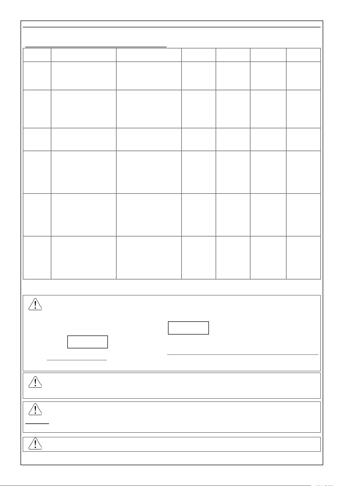
COMPARATIVE TABLES
CONTROL PANEL [CON BA.C:xx S]
CLAMP L1 L2 L3 L4 L5 L6 L7 L8 OC1 OC2 OC3
pre-associated
SOFTWARE ZONE
associated
SOFTWARE ZONE .... .... .... .... .... .... .... ....
pre-associated
SOFTWARE O.C. .... .... .... ....
associated
SOFTWARE O.C. .... .... .... ....
1 2 3 4 5 6 7 8 - - -
- - -
- - - - 1 2 3
- - - -
.... .... ....
KEYPAD [KEYPAD 01..08]
KEYPAD 1 2 3 4 5 6 7 8
L1 L2 L1 L2 L1 L2 L1 L2 L1 L2 L1 L2 L1 L2 L1 L2
associated
SOFTWARE ZONE
associated
SOFTWARE O.C.
.... .... .... .... .... .... .... .... .... .... .... .... .... .... .... ....
.... .... .... .... .... .... .... .... .... .... .... .... .... .... .... ....
- 7 -
Page 8

SATELLITE 01
CLAMP
pre-associated
SOFTWARE ZONE
associated
SOFTWARE ZONE
O.C.
associated
SOFTWARE O.C.
ZONE
pre-associated
SOFTWARE ZONE
associated
SOFTWARE ZONE
ZONE
associated
SOFTWARE ZONE
O.C.
associated
SOFTWARE O.C.
pre-associated
SOFTWARE ZONE
associated
SOFTWARE ZONE
O.C. SOFTWARE
associato
BASIC Inputs [Sat: I. BA xx] EXTENSION Inputs [Sat: I. EX xx]
BASIC Inputs [Sat: OC xx]
Detector [Sat: Sen xx]
Detector [Sat: Sen xx]
BASIC Inputs [Sat: OC xx]
BASIC Inputs [Sat: M.BA xx]
C8 - XSAT36 - XSAT PW
1 2 3 4 5 6 7 8 1 2 3 4 5 6 7 8
9 10 11 12 13 14 15 16
.... .... .... .... .... .... .... .... .... .... .... .... .... .... .... ....
1 2 3 4 5 6 7 8
........ ........ ........ ........ ........ ........ ........ ........
- - - - - - - -
XSAT WS - XSATHP - VIRTUAL XSATHP
1 2 3 4 5 6 7 8 1 2 3 4 5 6 7 8
9 10 11 12 13 14 15 16
.... .... .... .... .... .... .... .... .... .... .... .... .... .... .... ....
17 18 19 20 21 22 23 24 25 26 27 28 29 30 31 32
.... .... .... .... .... .... .... .... .... .... .... .... .... .... .... ....
1 2 3 4 5 6 7 8
........ ........ ........ ........ ........ ........ ........ ........
- - - - - - - -
XGSM485
1 2 3 4 5 6 7 8
9 10 11
........ ........ ........
........ ........ ........
- - - - -
- - - - -
- - - - -
SATELLITE 02
C8 - XSAT36 - XSAT PW
CLAMP
pre-associated
SOFTWARE ZONE
associated
SOFTWARE ZONE
O.C.
associated
SOFTWARE O.C.
ZONE
pre-associated
SOFTWARE ZONE
associated
SOFTWARE ZONE
ZONE
associated
SOFTWARE ZONE
O.C.
associated
SOFTWARE O.C.
pre-associated
SOFTWARE ZONE
associated
SOFTWARE ZONE
O.C. SOFTWARE
associato ........ ........ ........
BASIC Inputs [Sat: I. BA xx] EXTENSION Inputs [Sat: I. EX xx]
1 2 3 4 5 6 7 8 1 2 3 4 5 6 7 8
17 18 19 20 21 22 23 24
.... .... .... .... .... .... .... .... .... .... .... .... .... .... .... ....
BASIC Inputs [Sat: OC xx]
1 2 3 4 5 6 7 8
........ ........ ........ ........ ........ ........ ........ ........
XSAT WS - XSATHP - VIRTUAL XSATHP
Detector [Sat: Sen xx]
1 2 3 4 5 6 7 8 1 2 3 4 5 6 7 8
17 18 19 20 21 22 23 24
.... .... .... .... .... .... .... .... .... .... .... .... .... .... .... ....
Detector [Sat: Sen xx]
17 18 19 20 21 22 23 24 25 26 27 28 29 30 31 32
.... .... .... .... .... .... .... .... .... .... .... .... .... .... .... ....
BASIC Inputs [Sat: OC xx]
1 2 3 4 5 6 7 8
........ ........ ........ ........ ........ ........ ........ ........
XGSM485
BASIC Inputs [Sat: M.BA xx]
1 2 3 4 5 6 7 8
17 18 19
........ ........ ........
- - - - - - - -
- - - - - - - -
- - - - -
- - - - -
- - - - -
- 8 -
Page 9

SATELLITE 03
CLAMP
pre-associated
SOFTWARE ZONE
associated
SOFTWARE ZONE
O.C.
associated
SOFTWARE O.C.
ZONE
pre-associated
SOFTWARE ZONE
associated
SOFTWARE ZONE
ZONE
associated
SOFTWARE ZONE
O.C.
associated
SOFTWARE O.C.
pre-associated
SOFTWARE ZONE
associated
SOFTWARE ZONE
O.C. SOFTWARE
associato
BASIC Inputs [Sat: M.BA xx] EXTENSION Inputs [Sat: I. EX xx]
BASIC Inputs [Sat: OC xx]
Detector [Sat: Sen xx]
Detector [Sat: Sen xx]
BASIC Inputs [Sat: OC xx]
BASIC Inputs [Sat: M.BA xx]
SATELLITE 04
CLAMP
pre-associated
SOFTWARE ZONE
associated
SOFTWARE ZONE
O.C.
associated
SOFTWARE O.C.
ZONE
pre-associated
SOFTWARE ZONE
associated
SOFTWARE ZONE
ZONE
associated
SOFTWARE ZONE
O.C.
associated
SOFTWARE O.C.
pre-associated
SOFTWARE ZONE
associated
SOFTWARE ZONE
O.C. SOFTWARE
associato
BASIC Inputs [Sat: M.BA xx] EXTENSION Inputs [Sat: I. EX xx]
BASIC Inputs [Sat: OC xx]
Detector [Sat: Sen xx]
Detector [Sat: Sen xx]
BASIC Inputs [Sat: OC xx]
BASIC Inputs [Sat: M.BA xx]
NO CAPTURE 8
C8 - XSAT36 - XSAT PW
1 2 3 4 5 6 7 8 1 2 3 4 5 6 7 8
25 26 27 28 29 30 31 32
.... .... .... .... .... .... .... .... .... .... .... .... .... .... .... ....
1 2 3 4 5 6 7 8
........ ........ ........ ........ ........ ........ ........ ........
- - - - - - - -
XSAT WS - XSATHP - VIRTUAL XSATHP
1 2 3 4 5 6 7 8 1 2 3 4 5 6 7 8
25 26 27 28 29 30 31 32
.... .... .... .... .... .... .... .... .... .... .... .... .... .... .... ....
17 18 19 20 21 22 23 24 25 26 27 28 29 30 31 32
.... .... .... .... .... .... .... .... .... .... .... .... .... .... .... ....
1 2 3 4 5 6 7 8
........ ........ ........ ........ ........ ........ ........ ........
- - - - - - - -
XGSM485
1 2 3 4 5 6 7 8
25 26 27
........ ........ ........
........ ........ ........
- - - - -
- - - - -
- - - - -
NO CAPTURE 8
C8 - XSAT36 - XSAT PW
1 2 3 4 5 6 7 8 1 2 3 4 5 6 7 8
- - - - - - - - - - - - - - - -
.... .... .... .... .... .... .... .... .... .... .... .... .... .... .... ....
1 2 3 4 5 6 7 8
........ ........ ........ ........ ........ ........ ........ ........
XSAT WS - XSATHP - VIRTUAL XSATHP
1 2 3 4 5 6 7 8 1 2 3 4 5 6 7 8
- - - - - - - - - - - - - - - -
.... .... .... .... .... .... .... .... .... .... .... .... .... .... .... ....
17 18 19 20 21 22 23 24 25 26 27 28 29 30 31 32
.... .... .... .... .... .... .... .... .... .... .... .... .... .... .... ....
1 2 3 4 5 6 7 8
........ ........ ........ ........ ........ ........ ........ ........
XGSM485
1 2 3 4 5 6 7 8
- - - - - - - -
........ ........ ........
........ ........ ........
- - - - -
- - - - -
- 9 -
Page 10

SATELLITE 05
CLAMP
pre-associated
SOFTWARE ZONE
associated
SOFTWARE ZONE
O.C.
associated
SOFTWARE O.C.
ZONE
pre-associated
SOFTWARE ZONE
associated
SOFTWARE ZONE
ZONE
associated
SOFTWARE ZONE
O.C.
associated
SOFTWARE O.C.
pre-associated
SOFTWARE ZONE
associated
SOFTWARE ZONE
O.C. SOFTWARE
associato
BASIC Inputs [Sat: M.BA xx] EXTENSION Inputs [Sat: I. EX xx]
BASIC Inputs [Sat: OC xx]
Detector [Sat: Sen xx]
Detector [Sat: Sen xx]
BASIC Inputs [Sat: OC xx]
BASIC Inputs [Sat: M.BA xx]
SATELLITE 06
CLAMP
pre-associated
SOFTWARE ZONE
associated
SOFTWARE ZONE
O.C.
associated
SOFTWARE O.C.
ZONE
pre-associated
SOFTWARE ZONE
associated
SOFTWARE ZONE
ZONE
associated
SOFTWARE ZONE
O.C.
associated
SOFTWARE O.C.
pre-associated
SOFTWARE ZONE
associated
SOFTWARE ZONE
O.C. SOFTWARE
associato
BASIC Inputs [Sat: M.BA xx] EXTENSION Inputs [Sat: I. EX xx]
BASIC Inputs [Sat: OC xx]
Detector [Sat: Sen xx]
Detector [Sat: Sen xx]
BASIC Inputs [Sat: OC xx]
BASIC Inputs [Sat: M.BA xx]
NO CAPTURE 16 NO CAPTURE 8
C8 - XSAT36 - XSAT PW
1 2 3 4 5 6 7 8 1 2 3 4 5 6 7 8
- - - - - - - - - - - - - - - -
.... .... .... .... .... .... .... .... .... .... .... .... .... .... .... ....
1 2 3 4 5 6 7 8
........ ........ ........ ........ ........ ........ ........ ........
XSAT WS - XSATHP - VIRTUAL XSATHP
1 2 3 4 5 6 7 8 1 2 3 4 5 6 7 8
- - - - - - - - - - - - - - - -
.... .... .... .... .... .... .... .... .... .... .... .... .... .... .... ....
17 18 19 20 21 22 23 24 25 26 27 28 29 30 31 32
.... .... .... .... .... .... .... .... .... .... .... .... .... .... .... ....
1 2 3 4 5 6 7 8
........ ........ ........ ........ ........ ........ ........ ........
XGSM485
1 2 3 4 5 6 7 8
- - - - - - - -
........ ........ ........
........ ........ ........
C8 - XSAT36 - XSAT PW
1 2 3 4 5 6 7 8 1 2 3 4 5 6 7 8
- - - - -
- - - - -
NO CAPTURE 16 NO CAPTURE 8
- - - - - - - - - - - - - - - -
.... .... .... .... .... .... .... .... .... .... .... .... .... .... .... ....
1 2 3 4 5 6 7 8
........ ........ ........ ........ ........ ........ ........ ........
XSAT WS - XSATHP - VIRTUAL XSATHP
1 2 3 4 5 6 7 8 1 2 3 4 5 6 7 8
- - - - - - - - - - - - - - - -
.... .... .... .... .... .... .... .... .... .... .... .... .... .... .... ....
17 18 19 20 21 22 23 24 25 26 27 28 29 30 31 32
.... .... .... .... .... .... .... .... .... .... .... .... .... .... .... ....
1 2 3 4 5 6 7 8
........ ........ ........ ........ ........ ........ ........ ........
XGSM485
1 2 3 4 5 6 7 8
25 26 27
........ ........ ........
........ ........ ........
- - - - -
- - - - -
- - - - -
- 10 -
Page 11

SATELLITE 07
CLAMP
pre-associated
SOFTWARE ZONE
associated
SOFTWARE ZONE
O.C.
associated
SOFTWARE O.C.
ZONE
pre-associated
SOFTWARE ZONE
associated
SOFTWARE ZONE
ZONE
associated
SOFTWARE ZONE
O.C.
associated
SOFTWARE O.C.
pre-associated
SOFTWARE ZONE
associated
SOFTWARE ZONE
O.C. SOFTWARE
associato
BASIC Inputs [Sat: M.BA xx] EXTENSION Inputs [Sat: I. EX xx]
BASIC Inputs [Sat: OC xx]
Detector [Sat: Sen xx]
Detector [Sat: Sen xx]
BASIC Inputs [Sat: OC xx]
BASIC Inputs [Sat: M.BA xx]
SATELLITE 08
CLAMP
pre-associated
SOFTWARE ZONE
associated
SOFTWARE ZONE
O.C.
associated
SOFTWARE O.C.
ZONE
pre-associated
SOFTWARE ZONE
associated
SOFTWARE ZONE
ZONE
associated
SOFTWARE ZONE
O.C.
associated
SOFTWARE O.C.
pre-associated
SOFTWARE ZONE
associated
SOFTWARE ZONE
O.C. SOFTWARE
associato
BASIC Inputs [Sat: M.BA xx] EXTENSION Inputs [Sat: I. EX xx]
BASIC Inputs [Sat: OC xx]
Detector [Sat: Sen xx]
Detector [Sat: Sen xx]
BASIC Inputs [Sat: OC xx]
BASIC Inputs [Sat: M.BA xx]
NO CAPTURE 16 NO CAPTURE 8
C8 - XSAT36 - XSAT PW
1 2 3 4 5 6 7 8 1 2 3 4 5 6 7 8
- - - - - - - - - - - - - - - -
.... .... .... .... .... .... .... .... .... .... .... .... .... .... .... ....
1 2 3 4 5 6 7 8
........ ........ ........ ........ ........ ........ ........ ........
XSAT WS - XSATHP - VIRTUAL XSATHP
1 2 3 4 5 6 7 8 1 2 3 4 5 6 7 8
- - - - - - - - - - - - - - - -
.... .... .... .... .... .... .... .... .... .... .... .... .... .... .... ....
17 18 19 20 21 22 23 24 25 26 27 28 29 30 31 32
.... .... .... .... .... .... .... .... .... .... .... .... .... .... .... ....
1 2 3 4 5 6 7 8
........ ........ ........ ........ ........ ........ ........ ........
XGSM485
1 2 3 4 5 6 7 8
25 26 27
........ ........ ........
........ ........ ........
- - - - -
- - - - -
- - - - -
- 11 -
Page 12
Type of connections
L3 L4
L5
L6
L7
L8
T
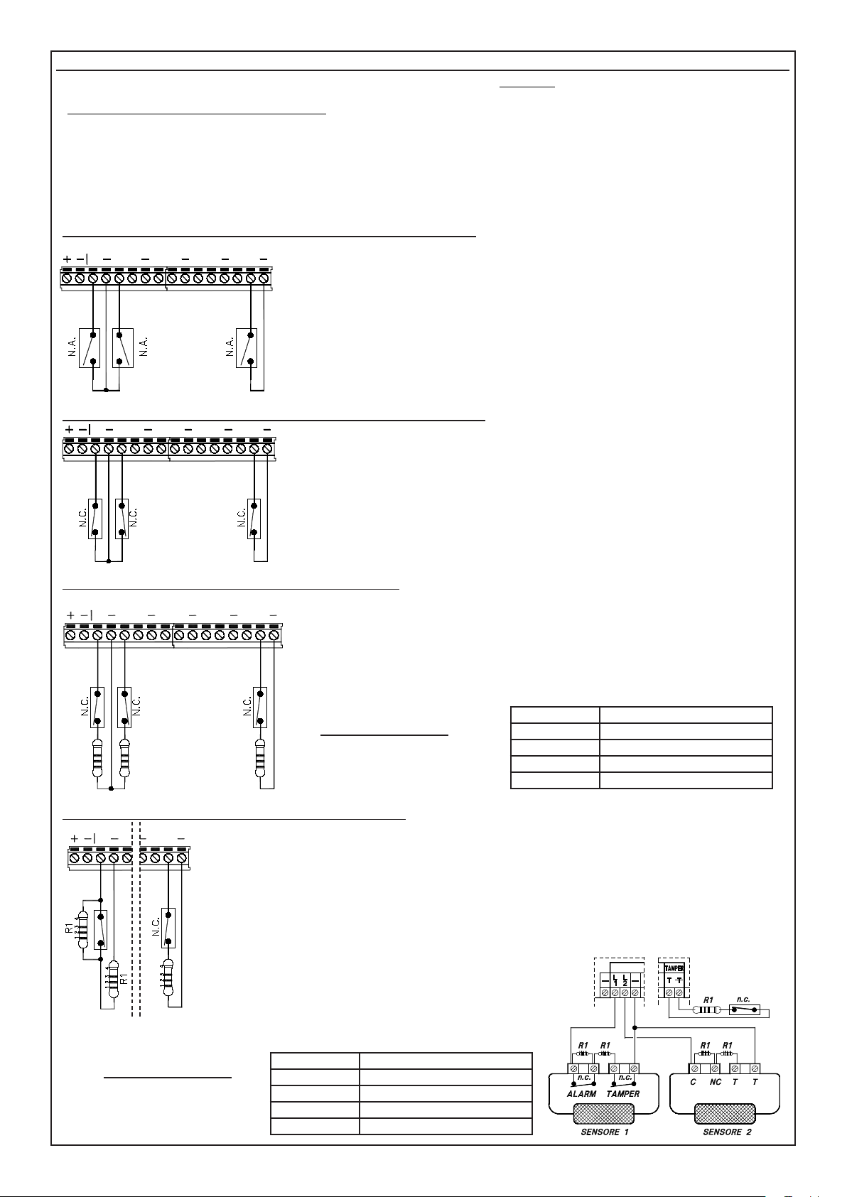
The CAPTURE central control unit has a basic conguration of eight inputs that can be individually programmed as:
- NO (Normally Open),
- NC (Normally Closed), which is the DEFAULT state,
- Inertial Vibration (balance with one 2300 ohm resistor)
- Inertial Roller Shutter (balance with one 2300 ohm resistor)
- Inertial Vibration NC (Normally Closed)
- Inertial Roller Shutter NC (Normally Closed)
- 1R (balance with one 4700 ohm resistor), in this case there will be only the alarm signal of the zone
N.B.:The equipment must be protected by using the TAMPER dedicated line or a different input zone of the control panel, programmed in TAMPER modality.
- 2R (balance with two 4700 ohm resistors), in this case there will be both the alarm signal and the tamper signal of the zone.
NO Zones (Normally Open Inputs) (NO XSAT36, XSATPW e XSATHP)
L2
L1 L3 L4
L7
L5
L6
T
L8
This conguration allows only the alarm status of the zone corresponding with the unbalanced
input to be recognised:
L1 - L8: Negative closing of the circuit in inputs from L1 to L8 triggers the alarm of the
corresponding zone.
T: Negative closing of the circuit of input T (normally used to protect the equipment) triggers
a TAMPER alarm.
NC Zones (Normally Closed Inputs) (NO XSAT36, XSATPW e XSATHP)
L2L1 L3 L4
L5 L7
L6
T
L8
This conguration allows only the alarm status of the zone corresponding with the unbalanced
input to be recognised:
L1 - L8: Negative closing of the circuit in inputs from L1 to L8 triggers the alarm of the corresponding zone.
T: Negative closing of the circuit of input T (normally used to protect the equipment) triggers
a TAMPER alarm.
Zones 1R (Balanced inputs with one 4700 ohm resistor)
L2
L1 L3 L4
L7
L5
L6
T
L8
This conguration allows only the alarm status of the zone corresponding with the unbalanced input to be recognised:
L1 - L8: Negative closing of the circuit in inputs from L1 to L8 triggers the alarm of the
corresponding zone.
T: Negative closing of the circuit of input T (normally used to protect the equipment) triggers
a TAMPER alarm.
Balancing resistance
R1 R1 R1
The colours of R1 terminal resistance are:
Zones 2R (Balanced inputs with two 4700 ohm resistors)
This conguration allows the central control unit to recognise both tamper and alarm status using the same zone circuit:
T
L1 - L8: The inputs of the zones programmed in this mode must be terminated with two 4700 ohm resistors. The rst
resistor (in parallel with the alarm contact of the sensor) identies the zone alarm while the second (in series with the
circuit) identies the tampering.
While referring to the gure at the side, when the contact is opened the central control unit detects the general alarm
status of the sensor, while the short circuit or clipping of the input circuit triggers a tamper alarm, even with the system
switched off.
T: The dedicated Tamper line is always balanced with a single termination resistor. The opening or short circuit of
input T (normally used to protect the equipment) triggers a TAMPER alarm.
R1
L2
L1
L8
R1 4.700 ohm
1) Yellow Value: 4
2) Purple Value: 7
3) Red Number of zeros 2
4) Gold Tolerance: 5%
R1
Balancing resistance
The colours of R1 terminal
resistance are:
Example:
The connection of two general sensors to two inputs programmed
as Zones 2R is shown by way of example.
Opening of the NC ALARM contact triggers an alarm status.
Opening of the NC TAMPER or a short circuit triggers the tamper
alarm of the corresponding input zone.
R1 4.700 ohm
1) Yellow Value: 4
2) Purple Value: 7
3) Red Number of zeros 2
4) Gold Tolerance: 5%
- 12 -
Page 13
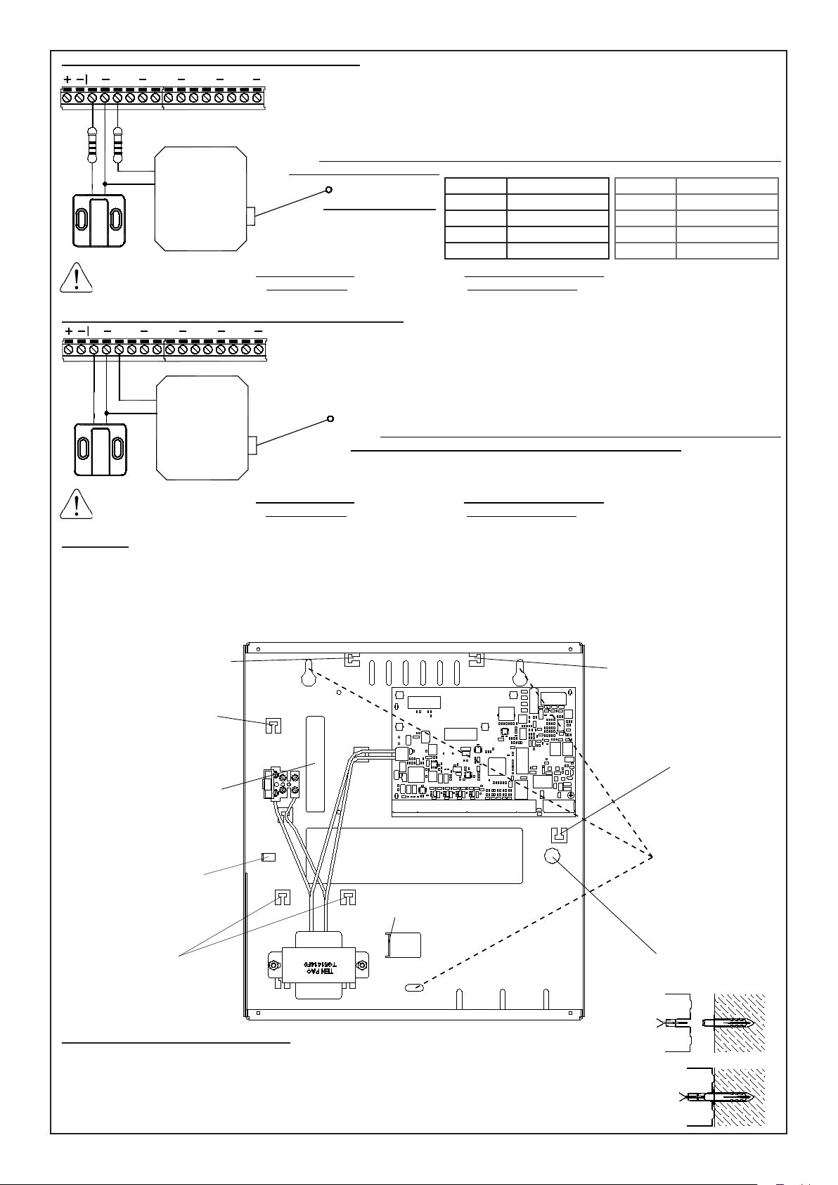
Inertial Vibration and Inertial Roller Shutter Zones
L1 L3 L4
R2
L2
L7
L5
L6
T
L8
R2
In those zones programmed as Inertial Roller Shutter, the central control unit does not signal the open zone if the connection cable is interrupted.
In those zones programmed as Inertial Vibration, the central control unit signals the open zone if the connection cable is interrupted.
These congurations permit direct management of Inertial or Roller Shutter sensors with one 4700
ohm R1 terminal resistor for the XSAT36 and XSATPW inputs and one 2200 ohm R2 terminal resi-
stor (not supplied, or two 4700 ohm R1 resistors in parallel) for the Capture central control unit, C8.
To adjust the sensitivity, the “Number of Pulses” step inside the programming of the single zone is
used (1= HIGH sensitivity / 120= LOW sensitivity). The equipment is protected using the dedicated
TAMPER line or an input zone other than the central control unit, programmed in TAMPER mode.
N.B.: this type of connection cannot be used in the zones in the A500 and A500 Plus keyboards
and the XSAT HP expansions.
Balancing resistance
The colours of R1 and R2
terminal resistance are:
R1 4.700 ohm
1) Yellow Value: 4
2) Purple Value: 7
3) Red Number of zeros 2
4) Gold Tolerance: 5%
R2 2.200 ohm
1) Red Value: 2
2) Red Value: 2
3) Red Number of zeros 2
4) Gold Tolerance: 5%
NC Inertial Vibration and NC Inertial Roller Shutter Zones
L2
L1 L3 L4
L5 L6
L7
T
L8
These congurations permit direct management of Inertial or Rolling Shutter sensors
with negative reference.
To adjust the sensitivity, the “Number of Pulses” step inside the programming of the
single zone is used (1= HIGH sensitivity / 120= LOW sensitivity).
The equipment is protected using the dedicated TAMPER line or an input zone other
than the central control unit, programmed in TAMPER mode.
N.B.: this type of connection cannot be used in the zones in the A500 and A500 Plus
keyboards and the XSAT 36, XSAT PW and XSAT HP expansions.
In those zones programmed as Inertial Roller Shutter, the central control unit does not signal the open zone if the connection cable is interrupted.
In those zones programmed as Inertial Vibration, the central control unit signals the open zone if the connection cable is interrupted.
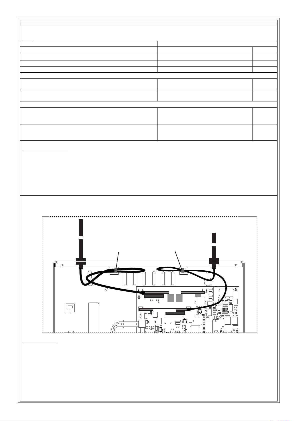
Installation
• In order to guarantee the correct system installation, it is important to lock the cables of the different equipment with the strips using the appropriate turrets of the housing .
• To guarantee electrical safety, the wires must be fastened with a clip directly on the protective sheath
• The 3 wires for the 230 V ~ mains power supply and the 2 wires for the power supply must be securely fastened together using a proper clip
(as shown in the gure) to prevent them coming into contact with sensitive parts of the central control unit if they should come loose from the
terminal block.
FOR GSM ANTENNA
CABLE FASTENING
WITH CLIP
FOR 230V POWER
CORD FASTENING
WITH CLIP
220V POWER SUPPLY
INLET HOLE
FOR WI FI ANTENNA
CABLE FASTENING
WITH CLIP
FOR TELEPHONE
CABLE FASTENING
WITH CLIP
FASTON FASTENING
YELLOW/GREEN CABLE
FOR EARTHING THE
COVER
FOR FASTENING
THE SIGNAL
SIGNAL CABLES
INLET HOLE
BATTERY
RETAINER
Anti-tamper KIT installation (Optional)
1. Perforate the wall in correspondence with the hole at the bottom of the housing destined for the anti-tamper.
2. Insert the wedge in the hole in the wall and tighten the spacer.
3. From the outside, insert the anti-tamper on the appropriate hole at the bottom of the housing.
4. Tightly x the housing on the wall, checking that the spacer screwed on to the wedge, presses against the antitamper
button spring.
5. Connect the cable of the strain relief KIT to the SNATCH JUMPER on the central control unit board.
- 13 -
HOLES
FOR WALL
MOUNTING
HOLE FOR
STRAIN
Page 14
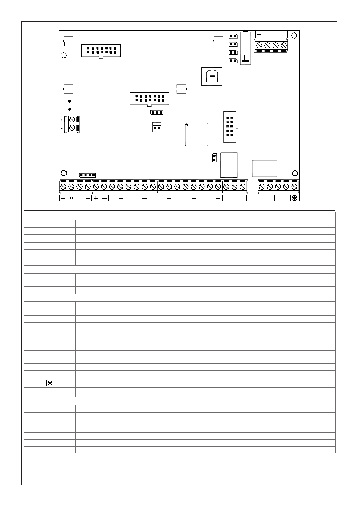
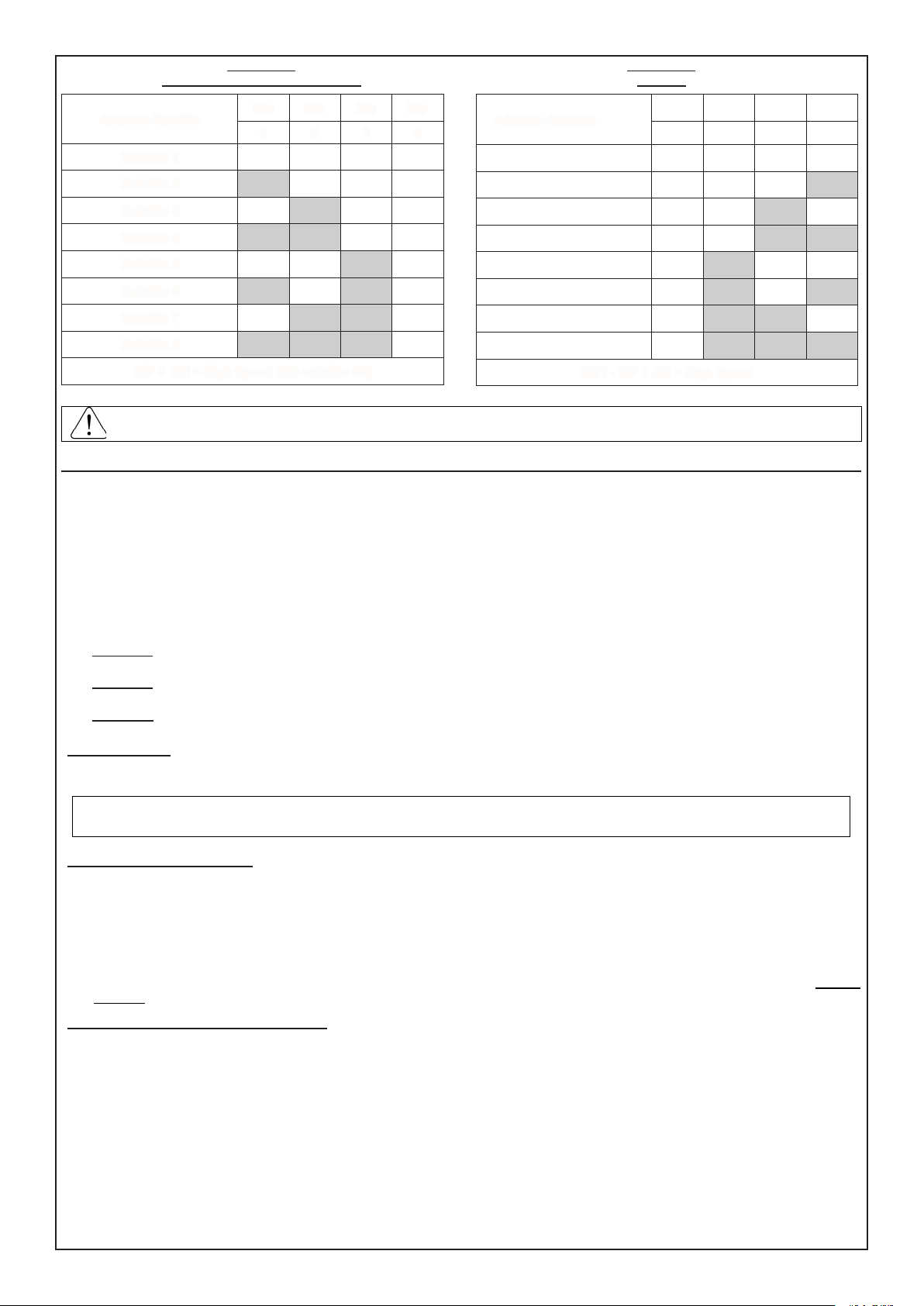
Control panel board CAPTURE 32, CAPTURE 16, CAPTURE 8
CONN GSM
J1
J2
S1
SNATCH
USB
TAMPER
PB1
OC1
OC2
OC3
CONN ETH
S5
1 2 3
J4
1
2
L5 L6
MEMORY
CARD
J5
SERVICE
C
L7
L8
NO NC
T
BATTERY
AC
DA DB
S7
L1 L3 L4
J3
L2
Terminal board, Jumper and Connectors CAPTURE 32, CAPTURE 16, CAPTURE 8
UPPER SIDE OF ELECTRONIC BOARD
J1_ CONN GSM connector for XGSM module (optional)
J2 - PLUG USB output for direct connection with PC through USB
S1 jumper for managing the anti-opening button (Open = Anti-opening Button management cut out)
TAMPER (x2) jumper for connecting additional anti-opening or strain relief protection (Open = At rest)
SNATCH jumper for connecting the strain relief button (Closed = At rest)
PB1 3 outputs Open Collector (OC1, OC2, OC3) and positive power (+) max 250 mA
LEFT SIDE OF ELECTRONIC BOARD
BATT
+ / -
supply output protected by resettable fuse for battery connection
AC supply input from the transformer
LOWER SIDE OF ELECTRONIC BOARD
+ DA DB -
output power and serial connection for keyboards, satellites, detectors HP, sirens HP, XGSM485 and XGSM485 PRO
modules
+ - supply output protected by resettable fuse for lines
L1 <---> L8 input lines
- negative reference for the input lines
T input tamper
[C] [NC] [NO]
auxiliary output with exchange free from voltages (positive safety) with capacity 3 A - 12 V =
(C) common exchange (NC) normally closed exchange (NO) normally open exchange
A B main telephone line input
A’ B’ telephone line output for connection of the derived internal telephone service
earth clamp
S7
connector for serial connection, reects the same order of the terminal (+, DA, DB, -)
CENTER OF ELECTRONIC BOARD
SERVICE close the jumper to reset the alarm and phone calls in progress (maintaining the arming state unvaried)
jumper for supplying power to the Ethernet module:
S5
- position 1 - 2 (left): module powered by the central control unit
- position 2 - 3 (right): module powered by an external source connected on J4
J3 - CONN ETH connector for Ethernet module (optional)
J4 polarized input connector 13.8 V = (1 = + and 2 = -), for external power supply of the Ethernet module
J5 - MEMORY CARD connector for connecting DIGIVOC voice synthesis board (optional)
A B A' B'
- 14 -
Page 15
Supply unit section
The power supply unit placed in the processing board is stabilised at 13.8 V = and limited in current at 1.2 A.
Table
Network power supply 230 Vac +10/-15% 50Hz
Voltage power supply nominal voltage 13,8 V =
Max. current absorbed by the network 135 mA
Maximum current available supply unit 1,2 A
Maximum current available - Excluding consumption control panel board (130 mA) OUTPUT: +/- serial, +/- detectors, + O.C. and sirens 900 mA
Output voltage at 230V~ +10%
Output voltage at 230V~ -10%
Keypad absorption with display A500
Keypad absorption with display A500 Plus
empty
with maximum charge
empty
with maximum charge
with disarmed display
with armed display
maximum
with disarmed display
with armed display
maximum
13,8 V =
13,6 V =
13,8 V =
13,6 V =
70 mA
90 mA
100 mA
70 mA
90 mA
220 mA
Outdoor connections
- Insert an omnipolar network switch having a minimum distance between the contacts of at least 3 mm in the electrical installation of the building.
- Place an eyelet terminal on earth wire and x it to the threaded turret marked with the earth reference.
- The control panel electronic board is earth connected through the metal turrets of the housing..
- For electric network power supply input, use double insulation cables.
Connections module XGSM and module EWEB WIFI
In order to guarantee the correct system installation, it is important to lock the cables of the different equipment with the strips using the appropriate
turrets of the housing
XGSM
FIXING POINTS OF
THE SUPPORTS FOR
XGSM MODULE
FIXING POINTS OF
THE SUPPORTS FOR
EWEB WIFI MODULE
XGSM
EWEB WIFI
EWEB WIFI
How to proceed
a. Completely disconnect the power supply, both network and battery.
b. Insert the appropriate plastic supports in the holes located on the control panel electronic board with the guides facing outwardsc.
c. Insert XGSM electronic board on connector J1 and EWEB or EWEB WIFI elettronic board on connector J3 making it slide inside the supports
guides until it stops.
d. Break the presetting on the control panel housing. Left to form XGSM module and right to form EWEB WIFI module.
e. Attach the antenna to the container using the prepared hole and secure the cable with a clamp as shown in Figure.
f. Insert the antenna and x by fastening the nut.
g. Connect the antenna cable to the GSM module.
h. Give power back to the control panel.
- 15 -
Page 16
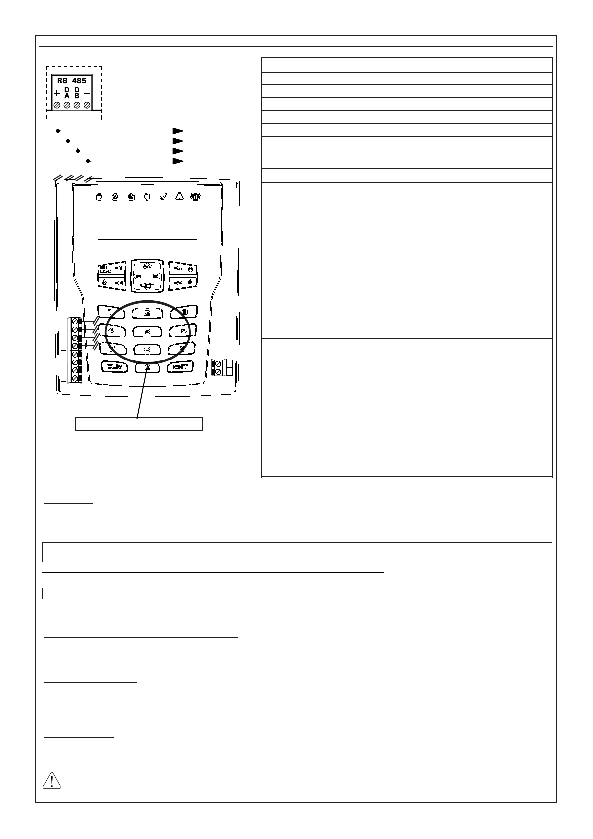
Keyboard A500 - A500 Plus
+
- - -
TL8 L9 L10
SPEAKER
TAMPER
+
DA DB
- - -
T2 T1
TL8 L9 L10
DA DB
T2 T1
TOY READER (A500Plus Only)
TOWARDS OTHER
KEYPADS
MIC SPK
L8 L9
Technical Features
16-character, 2-rows display screen
Self-updating micro ash
T1 input (with 4K7 resistance and negative reference)
T2 input is not used
20 Operational keys
1= ADDR (Address): 1
2= Tamper: Enabled
3= Mode: High Speed
Edit parameters
To access the modify menu for these parameters act as follows:
a. Press the “CLR” and “ESC” buttons at the same time, the display screen will
show the programmed model, rmware version and address.
b. When pressing the “ENTER” button, the display screen will show “Enter
Unlock Code for Cong”
c. Enter code “9698”, the display screen will show” 1=ADDR, 2=TAMPER,
3=MODE”
d. Enter the number of the parameter to be congured:
1= ADDR: select the address from 1 to 16 with the “ON” and “OFF” buttons. Once the address is selected, press “ENTER” to conrm and return
to the menu
2= TAMPER: press “CLR” to change the parameters, press “ENTER” to
conrm and return to the menu.
3= MODE: Do not change the factory-set parameter.
e. Press “ESC” to exit from the menu
The indications in the following layout must be complied with for the connections
of the keypad, connecting the clamps of serial output RS485 of the control panel
to the corresponding keypads clamps.
• On the same serial port RS485, up to 16 keypads (mod. A500 - A500Plus)
can be connected in parallel.
• We recommend sheathed cables with four wires of 0.5 mm each.
• The total length of the connection cable can be 600 meters and must be subdivided for all connected electronic boards.
The signal against the opening and the tearing of the keypad from the wall is
already connected and cannot be excluded from programming; therefore, we recommend arranging the Tamper spring pressing on the wall correctly and carefully
closing the keypad.
Wanting to exclude button completely tamper need to change the parameter 2
in keyboard.
Se si esclude il pulsante di antimanomissione, decade l’omologazione IMQ.
Addressing
If installation should require two or more activation points, the keyboards installed should have different addresses, not necessarily consecutive,
and the keyboards used should be enabled based on their addresses in programming.
Example: if 3 keyboards were installed, the rst keyboard can have “address 1”, the second “address 2” and the third “address 8”.
Bear in mind that there cannot be more keypads with the same address, otherwise they will stop working and the control panel will
activate a Tamper alarm.
By simultaneously pressing keys (CLR) and (ESC), it is possible to verify the correct addressing..
In this case, the correct addresses have to be programmed in the individual keyboards in order to restore operation (see “Edit Parameters”)
If there are keyboards properly addressed, but not enabled in programming, they signal “# x not connected” on the display.
In this case, the keyboards have to be enabled when programming the central control unit in order to restore operation.
Zones / Open Collectors connected in keypad
There is the possibility to connect up to two individually programmable zone and/or open collector inputs in every keyboard (see the chapter “Types
of connection”).
A500Plus TOY Reader
A reader for managing the TOY activators is built into the A500Plus keyboard.
For operation, it sufces to program the control mode in the central control unit and acquire the TOYs to use (see the chapters “Reader on A500Plus”
and “Accesses”).
A500 Plus Audio
An audio device for executing voice communications is built into the A500Pls keyboard.
To use it, it is not necessary to connect the SPK input. All you have to do is enable the various events to communicate in the central control unit
programming (see the chapters “Keyboard” and “A500Plus Audio”)
Check that the optional DIGIVOC module is in the central control unit..
- 16 -
Page 17

Audio keypads A500Plus enabling (user)
The audio enabling of the individual keypads is activated as follows:
- Enter user code with “Master” feature and access menu 1 on the keypad to be enabled
- Scroll the programming steps up to “A500 Settings” step
- Access the menu and adjust the “Audio Volume” on one of the possible settings (Mute - Low - Medium - High) using the key (CLR).
Note: “Mute” deactivates the audio of the keypad for any communication (events and zone state).
Audio “ZONES STATE” and keypads “EVENTS” enabling (user)
The audio ZONES STATE enabling of the individual keypads is activated as follows:
- Enter user code with “Master” feature and access menu 1 on the keypad to be enabled
- Scroll the programming steps up to “A500 Settings” step
- Access the menu and set the “Audio Zones State”/ “Audio OC state” / ”Audio events” on (YES/NO) using the key (CLR)
Audio enabling to the keypads (installer)
The enabling of the communications to the keypads is obtained:
- By setting the various events to be communicated on “YES” in “Audio A500Plus” menu.
- By setting the various sectors to be communicated on “YES” in “Audio A500Plus” menu.
- in menu “Keypads > A500 Settings > RTC A500” set to “YES” to enable the vocal management of the system directly with the keypad
- in menu “Keypads > A500 Settings > Audio events set to “YES” to activate the communications of the enabled events
- in menu “Keypads > A500 Settings > Audio zones state” set to “YES” to activate the communications of the associated inputs.
- in menu “Keypads > A500 Settings > Audio OC state” set to “YES” to activate the communications of the associated output OC
Display options and rear-lighting (user)
It is possible to vary the contrast, the intensity of the LEDS and the rear-lighting; to vary these options work as follows:
- Enter user code with “Master” feature and access menu 1 on the keypad to be enabled
- Scroll the programming steps up to “A500 Settings” step
- Access the menu and scroll downwards to entry “Reduc. Contrast - LED intens. red. - Rear-lighting”.
- Contrast Reduction: By setting “Yes” the contrast of the display is reduced
- LED Intensity Reduction: By setting “Yes” the brightness of the LEDS of the keypad is reduced
- Rear-lighting (%): Set the value (from 10% to 100%) of the rear-lighting intensity of the display and of the keypad.
RTC enabling on A600Plus keypad (user)
It is possible to activate the RTC directly on the A600Plus keypad with the same functions and use modalities of the RTC with telephone connection.
- Enter user code and press 7; (“RTCA500”: must be enabled in the “user prole”
- Insert the commands described on the user manual for RTC, press (ESC) to exit
Interruption of vocal repetitions (user)
It is possible to interrupt the cycle of the vocal repetitions of the keypads:
- Press key (3) of the keypad if in the user menu.
- Press key (3) followed by ENT if outside the user menu.
- 17 -
Page 18
Satellites
N.B. Expansion cards mod. C8 - XSAT36 - XSAT PW - XSATWS - XSATHP XGSM485 and must be connected to the RS485 serial situated in the
same way as keyboards.
For more information, refer to the manual of its satellites.
INPUTS OUTPUTS OPTIONS CONNECTIONS HOUSINGS CONSUMPTION
XSAT36
da V. 0.9 P4
XSATPW 3Q
XSATPW 5Q
da V. 0.9 P4
XSATWS
da V. 0.9 P4
XSATHP
da V. 1.0p5
XGSM485
da V. 1.2p0
n°10 to n°18 with expandable mod.
XEXP8
n°1 dedicated to tamper proof
n°1 re protection dedicated input
n°10 to n°18 with expandable mod.
XEXP8
n°1 dedicated to tamper proof
n°1 re protection dedicated input
n° 32 radio sensors
n° 32 sensors addressed
n° 4 in OR with the rst four sensors
(only balance 2R)
n°1 dedicated to tamper proof
n° 3
n°1 dedicated to tamper proof
n°1 additional alarm relay
n°8 programmable o.c. outputs, to
interface with relay module MR2 /
MR4 / MR8
n°1 additional alarm relay
n°8 programmable o.c. outputs, to
interface with relay module MR2 /
MR4 / MR8
n° 1 relay outputs C / NC pro-
grammable
n°1 Additional alarm relays
n°8 programmable o.c. outputs, to
interface with the relay module MR2
/ MR4 / MR8
n ° 1 output (FA) is working properly
n°3 programmable o.c. outputs, to
interface with the relay module MR2
/ MR4 / MR8
complete with
ower supply with
communications
a mains failure,
battery failure and
battery
link for additional
power supply with
communications
a mains failure,
battery failure and
battery
you can program
X1, X2, X3 is as
zone inputs and
as outputs OC or
both at once
With four wires
With four wires
With four wires ~ 45 mA
With four wires
With four wires
Single housing
CONTSAT W
Single housing
CONTCAPTURE
Single housing
CONTCAPTURE
Single housing
CONT SX
Single housing
CONT SX METAL
~ 50 mA
~ 50 mA
~ 250 mA
~ 320 mA
C8
n° 8
n°1 dedicated to tamper proof
n°8 programmable o.c. outputs, to
interface with the relay module MR2
/ MR4 / MR8
you can schedu-
le L1 .... L8 both
as zone inputs or
as outputs OC or
both at once
With four wires
Single housing
CONT SAT W
Single housing
CONT SX
~ 38 mA
X SAT WS: In the event of problems with receiving the radio signal, the XSATWS expansion boards with an address from 1 to 8 can
be programmed to manage the same sensors in pairs (max. 4 pairs).
When programming, in the step “Installation > Match XSATWS”, it is possibile to create 4 satellite matches:
Setting the rst to “yes” will match satellite 2 to satellite 1
satellite 3
XSATWS 3 with 4
NO
and so on for the other two pairs. All you have to do is acquire the sensors in the rst satellite of the pair
XSATWS 1 with 2
NO
, setting the second to “yes” will match satellite 4 to
for them to be automatically managed also by the second. Any remote control handsets will have to be acquired in both satellites, as
though they are independent.
Just one radio siren can be matched to the central control unit, and this can be acquired and managed by a single radio satellite.
XSATHP: The physical zone L1, L2, L3 and L4 inputs that manage only a type 2R connection are in OR with the rst four addressed
sensors. If, for example, there is both the sensor with address 1 and a sensor connected to terminal L1 of the satellite, the central control
unit would signal the corresponding zone in alarm status without specifying whether the actual sensor concerned is the one connected
to the terminal or is the serial sensor.
XGS485 and C8: The physical inputs can be individually congured as zone input or as Open Collector output with reference to negative;
or both programmings simultaneously (the line input is managed directly by activation of the corresponding O.C.).
WARNING: It is not possible to use the terminal as an OC output if programmed and physically cabled to control an external sensor and, similarly,
it is not possible to use the terminal as a zone input if programmed and physically connected to control a load with the OC output.
Please note that the tamper proof signals of the zones programmed with reading of the double balancing are managed
directly from the control panel.
- 18 -
Page 19
C8 - XSAT36 - XSATPW - XSATWS
Addressing
Addressing
XSATHP
Address Satellite
Satellite 1 Off Off Off Off
Satellite 2 On Off Off Off
Satellite 3 Off On Off Off
Satellite 4 On On Off Off
Satellite 5 Off Off On Off
Satellite 6 On Off On Off
Satellite 7 Off On On Off
Satellite 8 On On On Off
DIP 5 ON = High Speed (NO satellite C8)
The XGSM485 (from Version 1.2p0) does not require addressing. To be able to use the physical inputs on board, all that is necessary
when programming the central control unit is to enable a satellite in the “Satellite type” step and congure it as “XGSM485”.
Hints on armings management
The control panel enables four types of armings: ON, HOME, ZONE and PERIMETER. To every type of arming it is possible to arbitrarily associate
any zone set of the control panel.
When the control panel is armed in one of the four possible modalities, the zones associated to that modality are active and may signal alarm.
The arming of the control panel, if carried out with an external key, can happen in two different ways: impulsive or state.
The main difference between the impulsive and state modality is that in the rst, if the control panel has been armed using an external key it can
be disarmed using keypad and vice-versa, whereas in the second, the control panel cannot be disarmed using keypad as long as an external key
maintains it armed at state.
The control panel establishes a hierarchical order of the arming where the ON modality is the highest level one and the following modalities proceed in order HOME, ZONE and PERIMETER. This determines that if an arming is controlled and later one of higher level takes over, the control
panel passes to the highest level modality.
Dip Dip Dip Dip
1 2 3 4
Address Satellite (SW2)
Satellite 1 Off Off Off Off
Satellite 2 Off Off Off On
Satellite 3 Off Off On Off
Satellite 4 Off Off On On
Satellite 5 Off On Off Off
Satellite 6 Off On Off On
Satellite 7 Off On On Off
Satellite 8 Off On On On
SW1 - DIP 7 ON = High Speed
Dip Dip Dip Dip
1 2 7 8
• Example 1: the control panel is armed in HOME modality by an external state key. Later the ON arming is controlled by keypad. The control
panel passes to ON arming. If it is disarmed by keypad, it remains armed in HOME modality, until the external state key completely disarms it.
• Example 2: The control panel is armed in ON modality by an external state key. Later the ZONE arming is controlled by keypad. The control
panel remains armed in ON modality. If it is later disarmed by the state key, it passes to ZONE arming, until it is completely disarmed by keypad.
• Example 3: The control panel is armed from keypad in any modality. Later an impulsive key intervenes in any modality. The control panel
disarms. The same happens if the control panel is armed from impulsive key and then disarmed from keypad.
Key installation
The control panel can be armed from an external actuator as well as from the keypad; by means of the zone inputs suitably programmed as arming
in ON, HOME, ZONE or PERIMETER modality.
The zone inputs in satellite C8 can be congured as NC - NO - R1
If they are congured as R1, the resistors used must have a 4700 ohm value
Control Panel Programming
- Prog. Key: Program “Impulsive” or “State”, depending on the wanted management.
- Prog. Zone: Program a zone as ON Key: (Arming ON) therefore by unbalancing this clamp with a negative for a few seconds “Impulsive ma-
nagement” or maintaining the unbalancing “State management”, the control panel will switch on at ON modality and the zones programmed
as “Included at ON” will be considered fully active. The same is valid for the zone programmed as HOME Key: (Arming HOME), for the zone
programmed as AREA Key: (Arming AREA) and for the zone programmed as PERIMETER Key: (Arming PERIMETER)
N.B. The zones programmed as Key (ON- HO - AREA - PERI), must be associated to one sector only.
N.B. With “Impulsive Management”, the unbalance of a physical input programmed as Key ON/ HOME/AREA/PERIMETER executes a general
power off of the sector in any power on mode it is in.
Example of control panel programming
- Program zone L1 as ON Key,
- Program zone L2 as HOME Key,
- An Output O.C. must be programmed with modality “Cat. Armings - YES for ON HO ZO PE - memo all = YES” -> bistable time
- An Output O.C. must be programmed with modality “Cat. Sector - Re-balancing -> blk bistable time ->, to give the report of the State of the
affected Zones.
If the electronic key is used in IMPULSIVE modality, program the Mod. key functioning as Impulsive
If the electronic key is used in STAT E modality, program the Mod. key functioning as State
N.B. The above shown programming example is approximate.
N.B. Any input zone can become arming inputs.
- 19 -
Page 20

PSTN Telephone - Technical features
SERVICE
J5
MEMORY
CARD
J2
USB
SNATCH
TAMPER
S1
PB1
OC1
OC2
OC3
The PSTN telephone is directly integrated on the control panel electronic board, its functioning is subject to the enabling, during programming, of
the PSTN telephone section.
Outdoor connections: • internal changed and derived telephone line
Proles of phone numbers: • n° 16 numbers, can be associated to any alarm event or technical
Protocols: •
FAST FORMAT with assignable channels
•
VOCAL (with optional board mod. DGVOC)
•
SIA 1st Level and SIA 2st Level
•
SIA_HAYES for hayes XM40Plus modem or AVS certicate
•
CONTACT-ID
Time transmission of alarms ••D2 Vocal mode 12 sec., M2 vocal mode 12 sec.
D2 Contact ID 16 sec., M2 Contact ID 19 sec.
Type of interface • Proprietary interface compliant to ETSI ES 203-21 and RTTE
Connection of the telephone line
AB : connection to the incoming telephone line, upstream of all eventual system telephone
C
L7
L6
L8
NO NC
T
A B A' B'
DIGIVOC (optional) - Technical features
DIGIVOX is a device that, when inserted properly, provides the ability to centrally send voice messages
appliances.
A’B’: connection to the eventual system telephone appliances.
Note: x the telephone cable using the appropriate turret.
Protocols: • VOCAL
Messages: ••The control panel enables the recording of forty (n. 40) customised vocal messages for a total time of
120 seconds.
A library of pre-recorded messages allows automatic and personalized
composition of alarm messages and different technical events
RTC Remote Telephone Control: • Programmable activation for any single user prole
Tension: • Nominal tension: : 12 V =
Working Temperature: • temperature -10°C / + 55°C - humidy 95%
Consumption: ••in quiet: 10 mA
in transmission: 30 mA
Insertion in the board
OC1
OC2
OC3
PB1
a. Completely switch off the power to the control panel.
b. Insert the vocal synthesis board on the control panel board,
introducing the connector place in front of the board lower
face with the female J6 (Memory Card) placed on the
control panel board.
c. Press smoothly until its complete insertion.
d. Switch on the power to the control panel
CONN GSM
J1
CONN ETH
Plug-in
J3
S5
J4
1
BATTERY
AC
S1
TAMPER
SNATCH
J2
USB
MEMORY
CARD
J5
connector
SERVICE
S7
DA DB
L2
L1 L3 L4
L5 L6
C
L7
NO NC
T
L8
A B A' B'
PSTN + GSM
If you want to have both the phone line that the GSM channel, you must connect the telephone line to the control panel and insert the card XGSM
on Central or connect the card XGSM485 / XGSM485Pro in serial.
The calls management is subject to the type of interface chosen during programming..
- 20 -
Page 21
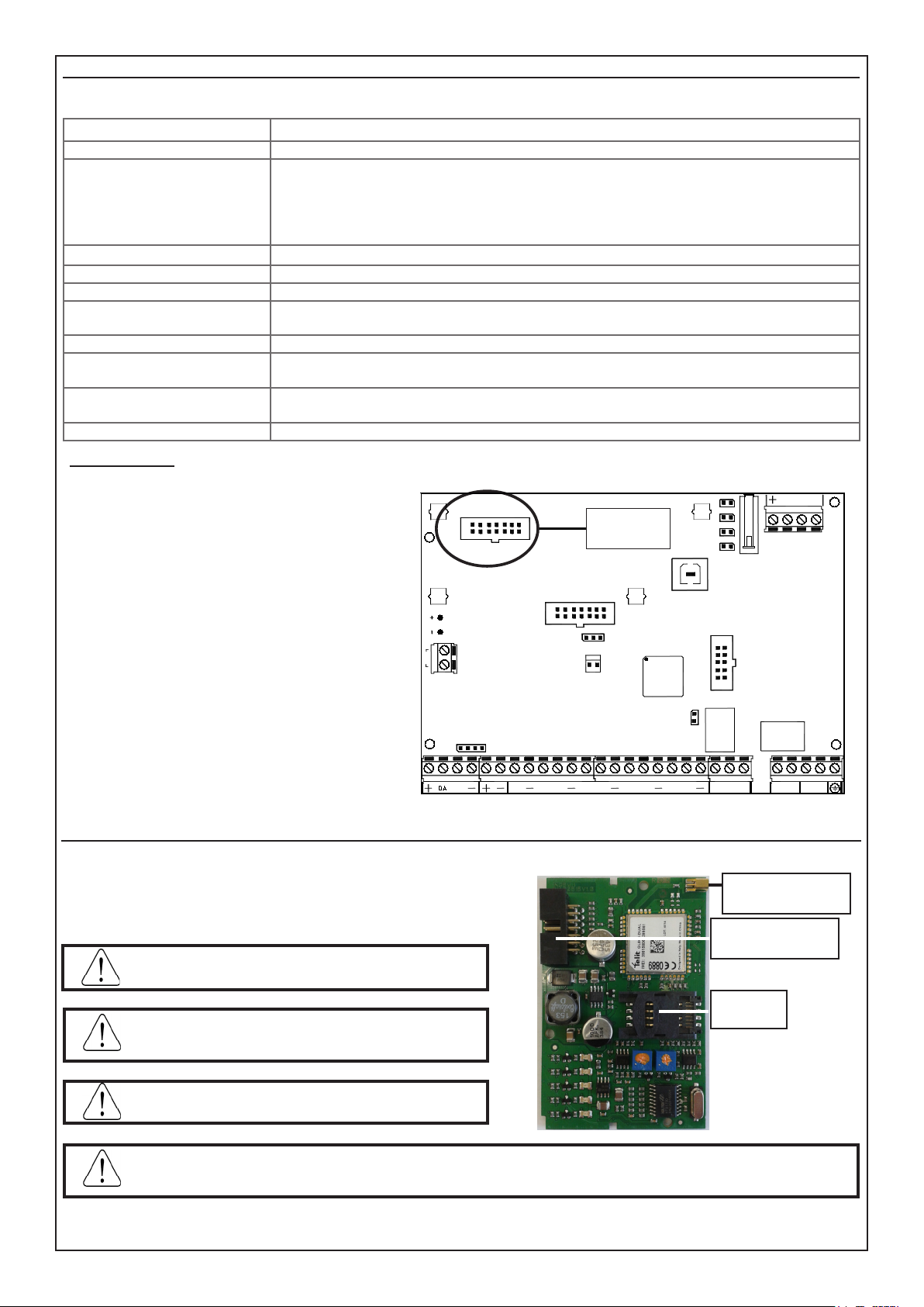
XGSM - Technical features
XGSM is a device which, when used with the Xtream central control unit, allows you to make and receive calls via the GSM mobile phone network.
Outdoor connections: • GSM Channel
Telephone numbers proles: • n. 16 numbers, that can be associated to any alarm or technical event
Protocols: •
FAST FORMAT with assignable channels
•
VOCAL
•
SIA
•
SIA 2nd level
•
CONTACT-ID
RTC Remote Telephone Control - • programmable activation for every individual user prole
Voltage: • nominal voltage: 12 V =
Environmental conditions: • temperatura -10°C / + 55°C - umidità 95%
Absorption: ••in quiete: 50 mA
in trasmissione: 400 mA
Electronic board sizes: • 93 x 15 x 60 mm
Declaration • The GSM modules used are compliant with R&TTE Directive 99/05/EC as
declared under the responsibility of the same manufacturer.
Time alarm transmission ••D2 Vocal mode 12 sec., M2 vocal mode 12 sec.
D2 SIA DC09 10 sec., M2 SIA DC09 10 sec.
Interface Type • Proprietary interface compliant to ETSI ES 203-21 and RTTE
How to proceed
OC1
OC2
a. Completely disconnect the power supply, both network
and battery
b. Insert the appropriate plastic supports in the holes loca-
ted on the control panel electronic board with the guides
facing outwards.
c. Insert XGSM electronic board on connector J1 making
it slide inside the supports guides until it stops.
d. Break the presetting on the control panel housing.
e. Pass the antenna cable through the hole and insert it on
the pre-settings as shown in the illustration.
f. Insert the antenna and x by fastening the nut.
g. Connect the antenna cable to the GSM module.
h. Give power back to the control panel.
CONN GSM
J1
BATTERY
AC
J3
Plug-in
connector
CONN ETH
S5
1 2 3
J4
2
1
S1
TAMPER
SNATCH
J2
USB
MEMORY
CARD
J5
OC3
PB1
SIM Card Inclusion/Antenna Connector Input
To insert the SIM Card:
1. Open the slide support
2. Insert the SIM Card in the presetting
3. Close the slide support until completely xed
Before inserting and removing the SIM Card, completely
remove power from the control panel.
Disable all call transfers
Deactivate the answering machine
Delete all SMS from the SIM
The warning of low SIM Card happens upon reaching
of the 8 Euros threshold.
If the security PIN code of the SIM card is not disabled it must be entered in the corresponding input step of the panel
programming menu. If a wrong PIN code is entered, the panel will execute maximum two attempts to activate the XGSM
module then stop, and will keep it blocked until a new PIN code is programmed. An error message will be displayed.
DA DB
S7
L1 L3 L4
SERVICE
L2
L5 L6
L7
T
L8
NO NC
C
A B A' B'
Antenna
Connector Input
Connector plug-in
central
SIM Card
position
- 21 -
Page 22

XGSM485 - XGSM485 PRO - Technical features
XGSM485 has a vocal synthesis module that contains 320 pre-recorded words that can be used to customize a maximum of 40 voice messages.
If the device does not interface with the control unit, XGSM485 can make absence of interfacing calls to the control unit.
The XGSM485 can take two SIM Cards. If both are installed, the main SIM (SIM A) is set by default and the system automatically switches to the
secondary SIM (SIM B) in the event of any of the following:
• No credit
• GSM network down
• No GSM eld
• GSM module operating faults
After switching to the Secondary SIM Card, the device sets a 240-minute timer for automatically switching back to the Main SIM Card. The device
may switch back the Main SIM Card earlier, however, if any of the above occurs to the second one in the meantime.
If the system uses both the XGSM and the XGSM485, the latter is set by default. If the central control unit detects a communication failure
or a fault with the GSM network of the XGSM485, it automatically switches to the XGSM module until the fault is corrected.
XGSM485 PRO can also connect to the switched line and to telephones downstream. In this case, when XGSM485 PRO detects a decrease in
line voltage (typically 48V), it connects any telephones downstream to its internal interface. In this situation, XGSM485PRO emits the free line tone
and waits for the number to be dialled (DTMF only). Once the number is dialled (recognised when there is a longer than anticipated pause after the
last digit of the DTMF) the mobile phone call sequence begins, during which the interface generates connected or engaged signals.
The power of the ring generator of the device permits activation of a limited number of ringtones.
Thus, it is recommended that a minimum number of cascade-connected phones be connected. This number can not be dened since
consumption during the ring phase varies from model to model.
XGSM485 and XGSM485 PRO TERMINAL BOARD
ANT GSM • Antenna cable plug connector
BATT + / - • Output for battery connection
+ • Positive power supply
DA DB • Control unit connection serial
- • Negative power supply
TI • Anti-tampering input with reference to the negative. Using this input, the anti-tamper button on the board is NOT considered.
TO • Anti-tampering input with reference to the negative. Using this input, the anti-tamper button on the board is considered.
- • Negative power supply
X1 • Manages point input coupled to terminal board 1 and/or open collector coupled to output O.C.1
X2 • Manages point input coupled to terminal board 2 and/or open collector coupled to output O.C.2
X3 • Manages point input coupled to terminal board 2 and/or open collector coupled to output O.C.3
+ VOUT
- VOUT
A B • PSTN telephone line input (only XGSM485 Plus)
A’ B’ • Telephone line input (only XGSM485 Plus)
••Positive power supply output protected by self-resetting fuse. Max. 100 mA
Negative power supply output
VARIOUS
SIM A • Main SIM card slot
SIM B • Secondary SIM card slot
RV1 • This is factory set, do not change
RV2 • This is factory set, do not change
LD1 • Red LED light “GSM module enabled”: Off when module is disabled, On when module is regularly enabled.
LD2
LD3
LD4
LD5 • Green LED light “Status indicator”: Flashing if the GSM module is in stand-by and connected to the GSM network; Fixed
S2 • Used to Manually RESET EEPROM
S3 ••Position 1-2: Tamper NOT ACTIVATED
USB • Connector for direct connection with Computer via USB
It turns on and off when there is a module malfunction.
• Greed LED light “GSM signal”: LED lights are off if there is poor signalling, LD2 on if there is signicant signalling, LD2
and LD3 on if there is a good amount of signalling - LD2 - LD3 and LD4 on if there is excellent signalling.
If the GSM module is interfaced; Off if the GSM module is not connected to the network (not working).
Position 2-3: Tamper ACTIVATED
TAMPER • Anti-tampering button, refer to terminals TI and TO
- 22 -
Page 23

XGSM485 Installation - Warnings
USB
TA MPE R
S3
X1 X2
USB
TA MPE R
S3
X1 X2
USB
TA MPE R
S3
X1 X2
XGSM485 should be positioned at least 1m away from sources of electromagnetic interference (ex.
transformers, power supplies, etc) and at the same time it should be the same distance away from
other equipment that can suffer from the electromagnetic radiation of the GSM, including the control
panel itself and its peripherals.
The XGSM485 module can be installed using the mod. CONT SX box or, in alternative, using the
mod. CONT SATW box in case a backup battery is needed (max. 12V 2.1Ah)
If mod. CONT SX is used, place the electronic board as indicated in the gure on the right
If mod. CONT SATW is used, please follow the instructions contained in the XGSM485 manual.
Warnings:
• Do not place the antenna in metal containers.
• Do not place the antenna near radio devices, whether they are transmitters or receivers.
• Before mounting the container, check the GSM signal level.
How to proceed:
a. Both the battery and mains power supply must be off.
b. Break up the tting on the CONT SX container.
c. Pass the antenna cable through the hole
d. Fix the XGSM485 to the CONT SX container
e. Insert the antenna and x it by tightening the nut rmly.
f. Connect the antenna cable to the GSM module.
g. Switch on the control unit power supply.
A
B
B
To insert the SIM Card:
sim
A
sim
B
If the security PIN code of the SIM card is not disabled it must be entered in the corresponding input step of the panel
programming menu. If a wrong PIN code is entered, the panel will execute maximum two attempts to activate the XGSM
module then stop, and will keep it blocked until a new PIN code is programmed. An error message will be displayed.
1. Open the slide support
2. Insert the SIM Card in the presetting
3. Close the slide support until completely
xed
TAMPER XGSM485 and XGSM485 PRO
TAMPER
TAMPER
1
TI
TO
1
TI
TO
External TAMPER between TO and - (negative):
with this connection, opening of both the EXTERNAL TAMPER and the TAMPER BUTTON in the board
are signalled.
Jumper S3 in position 2-3
External TAMPER between TI and - (negative):
with this connection, only opening of the EXTERNAL TAMPER is signalled.
Jumper S3 in position 2-3
- A: Antenna mounting set up
- B: Container mounting set up
Disable all call transfers
Deactivate the answering machine
Delete all SMS from the SIM
Before inserting and removing the SIM Card,
completely remove power from the control panel.
1
TI
TO
TAMPER
With Jumper S3 in position 1-2 the TAMPER is disabled.
Bridge between TO and - (negative):
with this connection, only opening of the TAMPER BUTTON on the board is signalled.
Jumper S3 in position 2-3
Terminals X1, X2, X3 operation (only XGSM485PRO)
The terminals X1, X2 and X3 can be congured as inputs for zones 1, 2 and 3 with single balancing (alarm only) or double balancing (alarm and
tamper), and as Open Collector outputs 1, 2 and 3 with negative reference; or both congurations at the same time (the line input is directly unba-
lanced by activation of the relative O.C.).
- 23 -
Page 24

Checking Credit and Expiry of the SIM Card for XGSM - XGSM485 and XGSM485PRO
Credit Check
This check is carried out cyclically regardless of the use of the GSM, or when the GSM module carries out operations using credit.
Upon reaching of the 8 Euros threshold, the keypad displays the LOW CREDIT strip and, if the calls for have been enabled in the telephone
“associate events”,
GSM Events 1
Prof. : nnnnnnnn
the telephone calls are made.
SIM Card Expiry Date Setting
This operation is necessary every time a SIM is recharged or is activated for the rst time, so that the control panel can notify, if enabled, of the
SIM Card expiry date.
We recommend setting the notice in advance compared to the same expiry date, to avoid blocks by the operator.
It is possible to display the residue credit, the level of GSM signal and vary the SIM Card expiry date by following the procedure described in the
User manual.
Recording of vocal messages
Depending on the equipment used (CAPTURE with DIGIVOC and XGSM485)it is possible the recording of forty (n. 40) customised vocal messages
for a total time of 120 seconds.
Every individual message can have a maximum recording time of 30 seconds.
These messages can then be used for communication of the control panel.
Recording with control panel procedure (CAPTURE e DIGIVOC):
To carry out recording, enable the RTC function and call the control panel on PSTN line.
Upon answering of the control panel enter the installer code and follow the vocal indications.
Should the PSTN telephone line not be available, simulate it using a switchboard.
Procedure:
1- Enable the PSTN telephone
2- Enable the RTC function
3- Call the control panel
4- Wait for the “enter code” control panel reply
5- Enter the installer code
Recording:
6- Press key (1) - await control panel communication where the number of the message we are about to record is shown.
7- Start speaking after having pressed key (#),
8- The recording automatically interrupts if you do not speak for more than 2 seconds.
Note: The various messages will be recorded one after the other and are numbered during recording in increasing order from
1 to 40 and are linked to the telephone memory locations from 376 onwards.
Commands:
[1] REC: Activates recording
[0] RESET: Activates the deletion of all messages
[3] TEL. OFF: ends the telephone communication
[5] PLAY: Plays the current message
[4] <: Goes back by one or more recorded messages
[6] >: Goes forward by one or more recorded messages
[#] ENTER: It is the conrmation command without which many of the other commands are not carried out
Deletion:
Note: it is not possible to delete an individual recorded message; the procedure, once activated, deletes all messages recorded on the customisable
memory.
Abilitaz. PSTN
SI
Num. squilli risp
>0 (0 .. 16)
Recording with XWIN software procedure XWIN (CAPTURE e DIGIVOC):
To record, follow the procedure with Xwin software and then transfer the telephone les in control panel and / or in the form XGSM485 always
using the same procedure used for programming.
- 24 -
Page 25

Vocal messages
CAPTURE has the possibility of forwarding specic vocal messages depending on the arisen events.
These messages can be technical or alarm and/or to reset the inputs.
Technical messages relate to situations like power supply anomalies, the absence of the telephone line or other, and are composed automatically
using the vocabulary of pre-recorded words shown in the Telephone Table; normally associated and placed before these messages, is the welco-
ming message where the installer usually records the address of the establishment where CAPTURE is installed and, if the sectors are enabled,
the message relating to the event belonging sector.
These messages (Welcoming and Sector Message) can be enabled or not to transmission for every individual prole of telephone numbers.
Zones automatic communications
Alarm/zones reset messages relate to the opening or closing of the inputs.
The opening/closing communications of the inputs are normally automatically composed by CAPTURE in relation to the type of line set during SIA
coding (ex. theft line or gas line etc.), to the zone number (1-32); normally associated and placed before this communication, is the welcoming
messages and, if the sectors are enabled, the message relating to the event belonging sector.
These messages (Welcoming and Sector Message) can be enabled or not to transmission for every individual telephone number.
Zones customised communications
Should it be necessary to customise the CAPTURE communications relating to the zones, by creating an additional message to the standard one,
it is possible to access the pre-recorded vocabulary and enter the code of the word in the “Vocal word 1-2-3- 4” steps, as shown in the “Telephone
Table” inside the telephone menu.
Zone par.
ENT
Iss. All / Rest.
YES
Vocal word 1
0 (max. 415)
Iss. zone coding
YES
Vocal word 2
0 (max. 415)
Iss. telephone zone
YES
Vocal word 3
0 (max. 415)
Iss. zone num.
YES
Vocal word 4
0 (max. 415)
For every individual input it is possible to customise the communication by imposing the control panel to “automatically” communicate or not the
words and have another 4 extra telephones available (“Vocal word 1-2-3-4”).
Welcoming message communication
The welcoming message is part of the 40 customisable by the installer and can be composed by:
1- Recorded welcoming message (usually the ES system reference: at the ofces of AVS Electronics S.p.A. in via Valsugana n. etc.)
2- Enabling or not of the sector reference (should the system be divided into more sectors, it would also be useful, in the vocal communication, to
have the sector reference in the communication).
3- Additional optional message (should the system be divided per sectors, it would also be useful, in the vocal communication, to have the sector
detail in the communication)
A message could be composed as follows:
“1” at the ofce of AVS Electronics S.p.A. in via Valsugana n. .. etc” - “2” sector 3” - “3” production “ - “ etc. etc.”
The enabling of the communication message happens using the programming step “account code/messages” from the telephone menu.
Under “Phone number > Associate Sector > Sector #”, introducing a value different from zero (0) in the “WORD” programming menu, it is possible
to activate the vocal announcement of the plant introducing message.
Presentaz. word
0 (0 .. 415)
Presentation word :
Introducing a value different from zero (0) will communicate the associated word (see word table).
Word sector
0 (0 .. 415)
Emis. num. sect.
NO
Presentaz. word
376 (0 .. 415)
Word sector
117 (0 .. 415)
Emis. num. sect.
YES
Sector word :
Introducing a value different from zero (0) will communicate the associated word (see word table), linked to the
associated sector.
Announcement of the SECTOR number:
Choosing “YES” will communicate “sector number” words.
Example :
· The introducing message recorded in the memory place n° 376, which corresponds to the 1 st recorded message,
is enable.
· The additional word n° 117 (garage) is enable
· The “sector number” word is enable
- 25 -
Page 26

Telephone Table - 1st
To every Telephone Code corresponds a certain default pre-recorded vocabulary that can be used to customise the vocal messages of the control
panel.
Phone
Code
Vocal
communication
Phone
Code
Vocal
communication
Phone
Code
Vocal
communication
Phone
Code
Vocal
communication
1 A • 81 DISARMING • 46 GATE • 178 NINETY_ONE
23 ABSENT • 161 DOCTOR • 118 GAZ • 171 NO
5 ACCESS • 208 DOOR • 125 GROUP • 172 NO
15 ACCOUNTANCY • 243 DOWNLOADING • 126 GSM • 174 NORTH
27 ACTIVATED • 104 EAST • 43 HEAT • 173 NOT
28 ACTIVATION • 190 EIGHT • 42 HEATER • 180 NOVEMBER
26 ACTIVE • 77 EIGHTEEN • 235 HEATING • 181 NUMBER
7 AGGRESSION • 187 EIGHTY • 12 HIGH • 191 OCTOBER
62 AIR_CONDITIONER • 188 EIGHTY_EIGHT • 13 HIGH • 183 OFF
11 ALARM • 189 EIGHTY_ONE • 92 HIGH • 273 OFFICE
65 ALLOWED • 89 ELECTRICAL • 276 HIGHER • 184 ON
88 AND • 90 ELECTRICAL • 128 HOME • 17 OPEN
16 ANOMALY • 91 ELECTROVALVE • 186 HOUR • 18 OPEN
19 APRIL • 93 EMERGENCY • 49 HUNDRED • 185 OPERATION
20 ARCHIVE • 2 ENABLED • 130 IN • 115 OUT
21 AREA • 110 END • 132 INCLUDED • 216 PANEL
3 ARMED • 94 ENTER • 133 INERTIAL • 193 PANIC
4 ARMED • 135 ENTER • 134 INPUT • 194 PARKING
136 ARMED • 14 ENVIRONMENTAL • 138 INSTALLER • 197 PARTIAL
24 ASSOCIATED • 98 ESCAPE • 139 INTERFERENCE • 198 PARTIALIZED
25 ATTIC • 275 EXCEEDED • 140 INTERNAL • 196 PARTITION
8 AUGUST • 99 EXCLUDED • 141 INTRUSION • 261 PARTITION
29 AUTOMATIC • 100 EXCLUDED • 142 IRRIGATION • 200 PERCENT
30 AUTOTEST • 102 EXCLUDED • 119 JANUARY • 203 PERIMETER
84 AVAILABLE • 101 EXCLUSION • 148 JULY • 202 PERIMETRICAL
33 B • 103 EXECUTED • 123 JUNE • 201 PERIPHERICAL
35 BALCONY • 97 EXHAUSTED • 51 KEY • 206 PLUS
36 BARRIER • 241 EXPIRATION • 71 KITCHEN • 209 PORTER'S_LODGE
249 BASEMENT • 240 EXTENSION_BOARD • 143 LABORATORY • 210 POWER
34 BATHROOM • 105 EXTERNAL • 204 LANDING • 211 PREALARM
39 BATTERY • 106 FAILED • 146 LEVEL • 212 PRESSURE
160 BEDROOM • 107 FALSE • 147 LIGHT • 214 PRODUCT
40 BLOCK • 108 FALSE • 145 LINE • 215 PRODUCTION
116 BURGLAR • 109 FEBRUARY • 22 LISTENING • 69 PROGRESS
41 C • 223 FIFTEEN • 268 LIVING_ROOM • 207 PUMP
48 CASE • 224 FIFTH • 37 LOW • 225 RADIO
47 CELLAR • 52 FIFTY • 38 LOW • 242 RANGE
45 CHILDREN_ROOM • 53 FIFTY_EIGHT • 233 LUMBER_ROOM • 228 RE_INCLUSION
56 CLEAR • 54 FIFTY_ONE • 230
57 CODE • 112 FINISHED • 80
MAINS
MANAGEMENT
• 137 READER
• 231 REAR
58 COMMAND • 11 4 FIRE • 158 MARCH • 232 RECOGNIZED
59 COMMERCIAL • 131 FIRE • 159 MASKING • 234 RESTORE
60 COMMON • 213 FIRST • 151 MAY • 227 ROBBERY
61 COMMUNICATION • 55 FIVE • 162 MEMORY • 251 ROLLING_SHUTTER
66 CONTACT • 10 FLOODING • 82 MESSAGE • 44 ROOM
67 CONTROL • 199 FLOOR • 165 MILE • 237 ROOM
50 CONTROL_PANEL • 205 FLOOR • 163 MINUS • 236 SATURDAY
68 CORRIDOR • 217 FORTY • 154 MISSED • 244 SECOND
70 CREDIT • 218 FORTY_EIGHT • 152 MISSING • 262 SECTION
72 D • 219 FORTY_ONE • 153 MISSING • 265 SEISMIC
127 DAMAGE • 222 FOUR • 96 MISTAKE • 248 SELECT
121 DAY • 221 FOURTEEN • 167 MODE • 260 SEPTEMBER
74 DECEMBER • 220 FOURTH • 149 MONDAY • 259 SEVEN
124 DEGREES • 64 FREEZER • 169 MULTIPLE • 76 SEVENTEEN
229 DEPARTEMENT • 63 FREEZING • 182 NEW • 256 SEVENTY
250 DETECTOR • 113 FRONT • 175 NIGHT • 257 SEVENTY_EIGHT
79 DIAL • 11 7 GARAGE • 179 NINE • 258 SEVENTY_ONE
238 DINING_ROOM • 120 GARDEN • 75 NINETEEN • 170 SHOP
271 DISARMED • 156 GARRET • 176 NINETY • 144 SIDE
272 DISARMED • 267 GARRET • 177 NINETY_EIGHT • 246 SIGNAL
- 26 -
Page 27

Telephone Table - 2st
To every Telephone Code corresponds a certain default pre-recorded vocabulary that can be used to customise the vocal messages of the control
panel.
Phone
The vocal messages recorded by the installer are memorised in control panel and correspond to the telephone codes shown in the table.
Vocal
Code
communication
44 ROOM • 245 SIXTEEN • 226 TEENAGERS • 312 TWENTY_EIGHT
237 ROOM • 255 SIXTH • 287 TELEPHONE • 313 TWENTY_ONE
236 SATURDAY • 252 SIXTY • 286 TELEPHONE_CALLS • 87 TWO
244 SECOND • 253 SIXTY_EIGHT • 288 TEMPERATURE • 306 USER
262 SECTION • 254 SIXTY_ONE • 78 TEN • 307 VALUE
265 SEISMIC • 274 SOUTH • 291 TERRACE • 3 11 VENTILATION
248 SELECT • 31 START • 289 THERMOSTAT • 314 VERANDA
260 SEPTEMBER • 73 STORE • 292 THIRD • 317 VOLUMETRIC
259 SEVEN • 83 STORE_ROOM • 296 THIRTEEN • 195 WALL
76 SEVENTEEN • 86 SUNDAY • 297 THIRTY • 150 WAREHOUSE
256 SEVENTY • 277 SUPERVISION • 298 THIRTY_EIGHT • 32 WARNING
257 SEVENTY_EIGHT • 9 SUPPLYING • 299 THIRTY_ONE • 318 WATCHDOG
258 SEVENTY_ONE • 270 SURVIVAL • 166 THOUSAND • 6 WATER
170 SHOP • 129 SYSTEM • 295 THREE • 168 WAY
144 SIDE • 266 SYSTEM • 269 THRESHOLD • 164 WEDNESDAY
246 SIGNAL • 278 TAMPER • 122 THURSDAY • 192 WEST
263 SIM • 155 TAMPERING • 294 TOTAL • 111 WINDOW
264 SIREN • 282 TAVERN • 157 TUESDAY • 95 WRONG
239 SITTING_ROOM • 283 TECHNICAL • 85 TWELVE • 319 ZERO
247 SIX • 284 TECHNICAL • 310 TWENTY • 320 ZONE
Telephone Table - recorded messages
Phone
Code
Vocal
communication
Phone
Code
Vocal
communication
Phone
Code
Vocal
communication
Phone
Code
376 Message 1: • 396 Message 21:
377 Message 2: • 397 Message 22:
378 Message 3: • 398 Message 23:
379 Message 4: • 399 Message 24:
380 Message 5: • 400 Message 25:
381 Message 6: • 401 Message 26:
382 Message 7: • 402 Message 27:
383 Message 8: • 403 Message 28:
384 Message 9: • 404 Message 29:
385 Message 10: • 405 Message 30:
386 Message 11: • 406 Message 31:
387 Message 12: • 407 Message 32:
388 Message 13: • 408 Message 33:
389 Message 14: • 409 Message 34:
390 Message 15: • 410 Message 35:
391 Message 16: • 411 Message 36:
Customised message recording by the installer
Phone
Code
Customised message recording by the installer
392 Message 17: • 412 Message 37:
393 Message 18: • 413 Message 38:
394 Message 19: • 414 Message 39:
395 Message 20: • 415 Message 40:
- 27 -
Page 28

RTC ACTIVATION BY A CALL FROM THE CONTROL PANEL
It is possible to activate the RTC function during an alarm telephone communication, by pressing key (7) after the two-tone signal. Subsequently,
the control panel will reply - ENTER CODE -. Now follow the indications shown in the paragraph below.
USER RTC ACTIVATION
1. Compose, using a telephone in DTMF (multifrequency or “tones”), the telephone number where the control panel CAPTURE is installed.
2. Upon reaching of the number of “Reply Rings” set for PSTN calls and at rst ring for GSM, a synthesized voice will say - ENTER CODE -.
• For calls through PSTN , if an answering machine is included, the overlapping can be activated:
a. Compose the telephone number and let it ring once.
b. Put the receiver back and call again, at least after 8 seconds and not after 20 seconds from the rst ring.
c. The control panel will reply at rst ring, - ENTER CODE -, or, only on GSM channel, “ENTER COMMAND” if the recognition of incoming
3. Slowly enter the User Code, which must be enabled for RTC functions; a synthesized voice will say - WELCOME TO THE REMOTE
4. The various functions can now be activated.
DTMF Commands
The commands are directly activated by pressing the keys on the telephone keypad. The DTMF commands described below are active or not,
depending on the prole to which the user is associated.
ATTENTION: there is an interdiction time of two minutes between an RTC call and the subsequent one that doubles if the code inserted in the
previous call is incorrect.
number procedure is enabled.
MANAGEMENT SYSTEM -; followed by - LIST AVAILABLE COMMANDS -
• [0] OFF ZONE: activates the possibility of excluding/including the input zones of the control panel from n. 1 to n. 32.
Example: [0] + (zone number) + (#)..
• [1] ESC: sector change.
• [2] MEM: listen to the events memory
• [3] TEL OFF: causes the total loss of the telephone communication
• [4] TEL OFF: causes the interruption of single telephone communication
• [5] OFF: causes the disarming of the control panel - CONTROL PANEL DISARMED -
• [6] O.C.: activates the possibility of controlling the Open Collector outputs from n. 1 to n. 250; activates only the
O.C. programmed as “O.C.User/Sect” by users enabled to the function “Enab. OC User”. Example: to control
the O.C. n. 2; subsequently press keys [6] and [2] followed by [#] or [6] [0] [2].
• [7] TEST: supplies information on the state of the control panel.
• [9] ON: causes the arming of the control panel in modality ON - CONTROL PANEL ARMED ON -
• [#] ENTER: it is pressed to conrm a data introduced by the keypad.
• [] STOP: it is pressed to interrupt a function (ex: the list of the events memory).
RTC USER with recognition of incoming number
This function enables the caller to communicate directly without having to enter the User code; active only for calls on GSM channel, therefore
the XGSM or XGSM485 is necessary. This function happens only if during programming the telephone number from which the RTC operation is
associated to a User enabled for RTC and to automatic “RTC validation”.
INSTALLER RTC ACTIVATION
• [0] RESET: Activates the deletion of all messages
• [1] REC: Activates recording
• [3] OFF TEL.: ends the telephone communication
• [5] PLAY: Plays the current message
• [4] <: Goes back by one or more recorded messages
• [6] >: Goes forward by one or more recorded messages
• [7] >: Enables reprogramming with XWIN through the GSM line of Central
• [#] ENTER: It is the conrmation command without which many of the other commands are not carried out
- 28 -
Page 29

Outgoing SMS Management
CAPTURE has the possibility of forwarding specic SMS messages depending on the arisen events.
These messages can be technical or alarm and/or to reset the inputs.
Technical messages relate to situations which power supply, battery or other anomalies, and are automatically composed by using a library of
pre-recorded SMS
Zone messages relate to signals of the zone inputs for alarm, reset and exclusion communications.
The zone SMS are composed by the sequence of the 4 standard words to which the zone strip is added.
Zone par.
ENT
Iss. All / Rest.
Incoming SMS Management
control panel arming #act on sector# #arm ho 2#
control panel disarming #sp sector# #sp 2#
sector state request #state sector N# #state sector 2#
sectors state request #sectors state# #sectors state#
Referred to: Open/Tamper/
Excluded/Supervision
zones state request #zones state# #zones state#
output state request #state output N# #state output 5#
YES
Type Syntax Example
oc activation #act number_oc# #act 13#
oc deactivation #deact number_oc# #deact 13#
zone exclusion #excl number_zone# #excl 36#
zone inclusion #incl number_zone# #incl 36#
zone state request
Iss. zone coding
YES
#state zone N# #state zone 2#
Iss. telephone zone
YES
Iss. zone num.
YES
It is possible to request the execution of remote controls from
the control panel by using suitably coded SMS.
The same operations envisioned for the vocal RTC connection
can be requested.
The incoming SMS messages are carried out only if:
- the sender telephone number is associated to a user
- the associated user is RTC enabled with automatic validation
depending on the telephone number
- are syntactically correct
- request actions for which the user is enabled
Commands List
More commands can be placed in line in the same SMS, as
long as:
- the total length does not exceed 43 digits
- the commands are separated by #
- every command is preceded and followed by #
The excess spaces are deleted
Example of correct sequences
#excl 12#excl 15#arm on 2#zones state#
Example of INCORRECT sequences
#excl 12#arm on 2#zones state
excl 12 arm on 2#zones state##
outputs state request #outputs state# #outputs state#
system state request
Referred to: technical
anomalies
conrm operations #res# #res#
calls block #stop# #stop#
Only command #answ# and the SMS of #state ... # envision the sending of a reply message; the others do not generate feedback (not even in
case of error).
The command #answ# sends, in one or more SMS, conrmation of the controlled operations; it can be included anywhere inside the SMS.
The command #system state# sends, in one or more SMS, also including:
- SIM CARD residue credit
The “zones” and “exclusions” sections contain the number list of the relative zones (number sequence separated by spaces).
An SMS is sent; every section is contained in only one SMS, but an SMS can contain more sections.
Should the individual section have such a size to exceed the max limit envisioned, the message is stopped and ended with suspension dots.
Example: #zone 1 2 23 open ...#
In this case, the exceeding parameters are not communicated.
#system state# #system state#
- 29 -
Page 30

Programming
Hints on sectors management
La CAPTURE includes the management of the sectors.
This means that up to 8 system in the CAPTURE 32, up to 4 system in the CAPTURE 16 and CAPTURE 8 independent between them can be
created with the control panel. In case of having to manage detectors in common between different sectors, associate them to the various sectors
to which they must refer.
These zones will only activate when all sectors to which they are associated are included.
The amount of sectors active in the system, meaning how many sectors exist therein independently, is dened during programming.
The sectors are useful when there is the need to have more systems managed by a single control panel. The normal applications, managing only
one system, do not require the use of this function, therefore only sector 1 will be active and all the zones associated to it.
Armings
The sectors can be activated in different modalities, one from the other. Example: sector 1 can be armed in ON modality, whereas sectors 2 and 3
are armed in AREA modality. Should there be, at any moment, zones associated to more sectors, these would result being automatically armed in
the lowest level modality present between the sectors to which they belong, where the highest level corresponds to arming ON and in decreasing
order, HOME, ZONE and PERIMETER.
Every zone used by the control panel must be associated to a sector and will result active when said sector is armed in an arming modality containing this zone.
The conditions that allow forcing are:
• Zone type Secondary FAILURE, MASKING
• Zone in antimask status
• Zone in survival status
• CENTRAL CONTROL UNIT AND SATELLITES
• Absence of network
• Power feeder failure
• Recharger failure
• Low voltage on ‘+’ power outputs and on ‘+ Vpot’ output
• Battery low / battery failure / no battery
The switch-on can be forced, using the relative controls contained in the guided user menu, accessible by pressing the ENT Key after gaining
access with the user code.
The conditions that do not allow forcing are:
• Central control unit tamper
• TamperSwitch KEYBOARDS / TamperCom KEYBOARDS
• TamperSwitch SATELLITE / TamperCom SATELLITE
• Radio interference
• TamperSwitch INSWCPU RS / TamperCom INSWCPU RS
• No Tel. Line / Tel. Line / GSM Fault malfunctions
• Zone camper status
• “TAMPER” or “ROBBERY” zone type open
• Primary FAILURE zone type open
• INSTANT zone type open
• internal instant and timed zones with “OFF times” open
Alarm outputs
The alarm outputs of the system activate when an alarm occurs in one or more sectors, but can only be deactivated by disarming the sector to
which the zone that caused the alarm in progress belongs. This is true for both the relay outputs and the Open Collector outputs. Certain functions
applicable to the Open Collector outputs require specifying the number of the sector of reference. Example: arming OC, OC from user, etc.
Keypads
The system keypads must be associated to one or more sectors. This determines which alarm messages are displayed therein The zone alarms
are shown only if relating to zones of the associated sectors. The technical alarms are always shown.
The quick arming function (Quick Arm) is linked to the keypad on which it is performed. With this procedure, the sector to which the keypad is
associated or, simultaneously, all sectors to which it is associated, is activated.
The “0 active zones” message, upon exiting the installer code, is displayed on keypad when the common zones are not associated to the four
different arming modalities (ON, HOME, ZONE, PERIMETER). This visualisation disappears when a user code is entered.
After having armed a sector, the “0 active zones” message is displayed on keypad to signal the user that there are no zones active in that arming
modality.
User Codes
The user codes must be associated to one or more sectors and have access to them only through the keypads associated to their sectors. If a code
is associated to one or more sectors and also set as “Master user”, it can access the sectors of competence from any keypad. When a user is
associated to more sectors and to the function “Sectors sum”, it can arm or disarm all systems (associated to it) simultaneously, by pressing 0 (zero).
The users associated to a specic sector, if enabled, can consult the control panel events memory, viewing only the events relating to their sector.
A user associated to all sectors can view the full events memory. With regard to the exclusion of the zones and activation of the O.C. outputs from
keypad, the user is enabled to work only on zones and O.C. under the responsibility of its sector; if the O.C. is associated to more sectors, it will
be managed by all users linked to the same sectors of the O.C..
Example of keypad behaviour
User 1 associated to sectors 1, 2, 3, 4 and set as “Master user -> NO”
The Users 2/3 are set as “Master user -> NO”
Users/Sectors KEYPAD (sector 1, 2, 3, 4) KEYPAD (sector 1) KEYPAD (sector 2)
USER 1 (sector 1, 2, 3, 4) sectors choice display sector 1 display sector 2
USER 2 (sector 1) display sector 1 display sector 1 unauthorised
USER 3 (sector 2) display sector 2 unauthorised display sector 2
Only User 1 associated to sectors 1, 2, 3, 4 and set as “Master user -> YES”
Users/Sectors KEYPAD (sector 1, 2, 3, 4) KEYPAD (sector 1) KEYPAD (sector 2)
USER 1 (sector 1, 2, 3, 4) sectors choice sectors choice sectors choice
USER 2 (sector 1) display sector 1 display sector 1 unauthorised
USER 3 (sector 2) display sector 2 unauthorised display sector 2
- 30 -
Page 31
15 DIC 06
00 : 00 : 15
PROGRAMMING
00 : 00 : 15
Capture ...
avs electronics
Installation
ENT
Keypads
Ynnnnnnn
Satell.
nnnnnnnn
Sirens
nnnnnnnn
Satellite type
ENT
Satell. add. 1
XSAT36/PW/S.POW
Enter Installer Code followed by (ENT)
(by default: Installer Code 1 = 000000; Installer Code 2 = Disabled)
If the code is recognised, the wording “Capture 32/16/8” will appear
Press (ENT) to enter
SOME PROGRAMMING VALUES MIGHT NOT CORRESPOND TO THOSE ON THE KEYBOARD BECAUSE THEY
RELATE TO THE CAPTURE 32 CENTRAL CONTROL UNIT E.G.: User Code (1 - 128) instead of User Code (1 - 64).
Installation
Keypads: By setting “YES”, the individual keypad connected on serial is enabled
Satellite: By setting “YES”, the individual satellite connected on serial is enabled
Sirene (seriali): By setting “YES”, the individual siren connected on serial is enabled
Note: It is possible to install the various accessories not in sequential order; it is therefore possible to enable the
serial 7 accessory even without having installed the previous ones.
Satellite type: The type of satellite model connected is dened;
Satellite address xx: indicates which satellite we are programming from 1 to 8.
This step is used to dene which types of satellites have been connected to the serials; with this pogramming a
series of controls are activated, used to avoid performing programming errors during association of the software
zones to the physical ones.:
- XSAT36/XSATPW/S.POW: The XSAT36 is a wired satellite with a maximum of 36 zones. The XSATPOWER has
the same characteristics as the XSAT36 with the addition of management of its power supply unit. The XPOWER
is a satellite for sole management of its power supply unit.
- XSATWS: it is possible to acquire up to 32 radio detectors
- XGSM485: wired satellite with maximum 3 single or double balancing inputs and/or 3 O.C. outputs.
- XSATHP: wired zone extension peripheral that adds up to 3 normal EOL inputs and up to 32 wired addressable detectors.
- Virtual XSATHP: software function that simulates an XSATHP and allows connecting up to 32 addressable
detectors directly to the serial buses of the control panel.
WARNING!!! Only one single Virtual XSATHP is supported in the conguration of the panel.
WARNING!!! The Virtual XSATHP function CANNOT BE USED if using physical XSATHP devices connected to the panel.
Pairing XSATWS
ENT
XSATWS 1 with 2
NO
List sat.->BIP
ENT
Position #
1 (1..8)
Satell. addr.
0 (0..8)
Virtual XSATHP
ENT
Sensors
nnnnnnnnnnnnnnnn
EWEB / EWEB WIFI
NO
Pairing XSAT WS: This menu is used to establish which radio satellites must work in pairs.
The rst value corresponds to satellites 1 and 2, the second to satellites 3 and 4, the third to satellites 5 and 6, the
fourth to satellites 7 and 8
To access other entries press () or ()
List sat.->BIP: This menu is used to dene a sequential order between the various radio satellites.
Position X: This sequential order denes that the remote controls acquired on the rst satellite will be from number
1 > 64, those acquired on the second satellite will be from 65 > 128, those acquired on the third satellite will be
from 129 > 192 and so on.
Satellite address: indicates the address of the satellite saved in this position.
Virtual XSATHP: This menu allows you to dene what are the sensors connected and managed directly by the
serial port of the system. Detectors connected to the serial port must be numerated from 1 to 16.
Sensors: Setting “YES”, enables the single sensor with serial connection (HP series).
EWEB/EWEB WIFI: Setting “YES”, enables the EWEB / EWEB WIFI board
Press (CLR) to vary
Press arrows () and () to position the cursor
To access other entries press () or ()
Write the number to be set
Press (ENT) to conrm
to following
page
- 31 -
Page 32

from previus
page
PSTN enable
NO
XGSM
NO
XGSM485
NO
Conditional arm
YES
Code R. to det
NO
Conform.EN50131
Test EN solo dgt
Sys. events count
10 (0 ..10)
Country
Italy
Ctr. panel label
NO
NO
Installation
PSTN enable: By setting “YES”, the PSTN integrated dialler is enabled to dial the programmed calls.
XGSM: By setting “YES”, the GSM integrated dialler is enabled to dial the programmed calls.
XGSM485: By setting “YES”, the GMS dialler with serial connection for making the programmed calls is enabled.
Conditional arm: By setting NO, the control panel is armed anyway, even if there are unbalanced lines or tamper signals.
By setting YES, the control panel analyses the state of the zones, when an arming command is given; even if there
is only one u nbalanced immediate zone, the control panel is not armed.
Example: if wanting to avoid sending useless signals, for a manoeuvre error, the setting must be YES.
NOTA: Impostando NO decade la conformità alle Norme EN50131.
Code Reset to Default: By setting “NO”, the “Reset Codes” procedure returns just the Installer Code to its factory
setting. By setting “YES”, the “Reset Codes” procedure returns all programming to the default settings.
EN50131 conformity: By setting “NO” or if certain parameters are edited (see the “EN50131 - Grade 2 Conformity”
section) the unit no longer complies with EN50131 standards.
Test EN of Digital numbers only: By setting “NO”, the test of the phone numbers set by EN50131 comprises all the
programmed phone numbers. By setting “YES”, the test of the phone numbers only comprises the phone numbers
programmed with digital protocol.
System events count: It is the number above which repetitive Tamper or Fault events relating to the central control
unit and the various peripherals connected (Satellites, Buzzers, etc. excluding zone inputs) no longer cause the
programmed outputs to enter alarm mode, but are instead listed and saved in the event memory; by setting the
value 0 (zero) as the code number, the function is eliminated and none of the events are coded.
WARNING: this function is re-enabled with the rst change of status (ON/OFF) of the Partition with which the
peripheral is associated. NOTA: Impostando 0, 1 o 2 decade la conformità alle Norme EN50131.
Country: Adjusts the control panel to the local behaviours/electric standards.
NOTE: setting the nation as “BELGIUM” automatically guarantees compliance with T014 with regard to resetting
the TAMPER Alarm
Control Panel Label: 16 alphanumerical string, indicated when access to the programming menu
Partitions
ENT
Partition #
1 (1 ... 8)
Zones 1
YYYYYYYYYYYYYYYY
Exit time
MM:SS 1: 0
Entry time
MM:SS 0: 30
Buzzer announce
0 (0.. 60)
Patrol tour time
0 (0.. 255)
Double check
0 (0.. 255)
Partition label
to following
page
Press (CLR) to vary
To access other entries press () or ()
Write the number to be set
Press (ENT) to conrm
Partitions
Partition: Select which partition we are programming from 1 to 8.
Zone: By setting YES, the zone is associated to the partition; the zones can be associated with more than one
partition; in this case they will be common to the partitions they are associated with.
By default, all zones are associated to partition 1. In this way, the system can immediately manage a single system.
Exit time: Exit time of the timed zone and 24H timed associated to the partition
Entry time: Entry time of the timed zones and 24H timed associated to the partition
Buzzer announce: it is possible to ensure that the automatic armings are pre-warned by a beep, on the enabled
keypads, for a time programmed under “warning duration”. During this period of time, by entering an enabled code,
it will be possible to delay arming by one hour (extraordinary inclusion).
Ex. If 5 minutes are programmed, it starts to sound 5 minutes before arming.
NOTE: in the event of use of the timing programming, to prevent the voiding of compliance with EN50131, a warning
time must be programmed.
Patrol tour time: is programmed in minutes, once timer is expired, the patrol partition is re-armed at ON. Essentially,
the function means that any user code with a patrol tour attribute associated with this partition turns off the partition for
the period of the programmed patrol timer. When the patrol tour timer elapses, the partition reverts to its initial work
mode. In case of reset or watchdog, the patrol partitions automatically activate.
Double check: in seconds; in the case of a user code congured with “Double consent” or with TOY, this denes
the period for recognition with the keypad of a second user code or coupled TOY congured with “Double consent”.
Partition label: it is possible to associate a description of 16 alphanumerical digits for every partition
Press (CLR) to vary
Writing keys::
(1)abc1 (2)def2 (3)ghi3 (4)jkl4 (5)mno5 (6)pqr6 (7)stu7 (8)vwx8 (9)yz. (0)_’0
Press arrows () and () to position the cursor
Press (ENT) to conrm
- 32 -
Page 33

from previus
page
Macro
ENT
Macro #
1 (1.. 64)
Operat. #
1 (1.. 8)
Operation Type:
Arm. HO Part.
Partition #
1 (1.. 8)
Zone timers OFF
Label
Macro
The Macros (maximum 64) allow the user to carry out various operations at the same time (maximum 8) using
the same command:
Type of Operation:
Operation Type:
Arm. HO Part.
Partition #
3 (1.. 8)
Zone timers OFF
NO
Operation Type:
Attiva O.C.
O.C. #
3 (1.. 32)
Operation Type:
Escludi zona:
Zone number
5 (1.. 32)
Label: it is possible to associate a description of 16 alphanumerical digits for every Macro
• Arm. ON Part.
• Arm. HO Part.
• Arm. AR Part.
• Arm. PE Part.
• Disarm. Part.
Example: Starting in ON modality of Partition 3, disabling the input and output timers of
YES
the timed zones associated with this Partition.
• Activ. O.C.
• Deactiv. O.C.
Example: Activation of the O. C. 3
• Exclude zone:
• Re-incl. zone:
Example: Exclusion of zone 5
With this type of operation it is possible to enter a preselected
modality, ON - HOME - AREA - PERIMETER, and disarm and
manage the “Zone timers OFF” function of the Partition selected in the submenu.
With this type of operation it is possible to activate or deactivate the Open Collector selected in the submenu.
With this type of operation it is possible to exclude or re-include the zone selected in the sub-menu.
Press (CLR) to vary
To access other entries press () or ()
Writing keys::
(1)abc1 (2)def2 (3)ghi3 (4)jkl4 (5)mno5 (6)pqr6 (7)stu7 (8)vwx8 (9)yz. (0)_’0
Press arrows () and () to position the cursor
Press (ENT) to conrm
to following
page
- 33 -
Page 34

from previus
page
Zones
ENT
Zone numbers
1 (1 .. . 32)
Phisical input
CPN I.BA 1
Zone type
Delay T1
Zones
Zone numbers: For every “software” zone it is possible to associate a physical input corresponding to the “clamp” where
the detector was wired.
Press (CLR) to vary
To access other entries press () or ()
Press arrows () and () to position the cursor
Press (ENT) to conrm
Entries description
A - CPN = CONTROL PANEL, EXP= SATELLITE, KBD= KEYPAD
B - n. x = SATELLITE ADDRESS (appears only if A = SAT/PAD)
C - I.BA = BASIC INPUT I.EX = EXTENSION INPUT
D - n. x = INPUT NUMBER
Example: In the example at the side, the software zone is linked to the physical input that
corresponds to - SATELLITE n. 5 - connected on BASIC INPUT- number 3
Zone type: for every input line of the control panel it is possible to determine the type of line.
• Not used: the zone is not considered from the control panel analysis.
• Istant: zone that causes an immediate alarm when it unbalances with control panel armed.
• Conditional: immediate zone that is automatically excluded during the input and output time of a timed zone; in case of
more timed zones, reference must be made to that with the longest time. With control panel armed the unbalancing of this
input causes an immediate alarm when the output time or the return time are not in progress.
• Dealy T1: upon arming of the control panel the output time becomes active, signalled by the intermittent sound of the
keypad buzzer. After this time, if the input is unbalanced, the return time is made available, signalled by an intermittent, highly
frequent, sound; after expiry of this time an alarm is activated, unless the control panel has been in the mean time disarmed.
• Inst. perm. esc. (Immediate permanent esclusion): immediate zone that is automatically excluded if unbalanced at the
time of arming the control panel; it remains excluded until disarming of the same control panel.
• T1 Perm. escl. (Timed Permanent esclusion): these are timed zones with permanent exclusion. They are automatically
excluded if resulting unbalanced at the end of the output time; they remain excluded until disarming of the same control panel.
If it is balanced at the end of the output time, when it is next balanced, the zone will be timed with the input time.
• Ist. temp. escl (Immediate with temporary esclusion): it is automatically excluded if it results unbalanced upon arming
of the control panel; it is automatically included upon its re-balancing.
• T1 Temp. escl. (Timed with temporary esclusion): these are timed zones with permanent exclusion. They are automatically
excluded if resulting unbalanced at the end of the output time; they remain excluded until disarming of the same control panel.
If it is balanced at the end of the output time, when it is next balanced, the zone will be timed with the input time.
• Key ON: zone for remote arming in ON modality; therefore, the unbalancing of the zone in this way programmed will cause
the arming of the control panel in ON modality, activating the relative associated zones.
• Key HOME: zone for remote arming in HOME modality; therefore, the unbalancing of the zone in this way programmed will
cause the arming of the control panel in HOME modality, activating the relative associated zones.
• Key AREA: zone for remote arming in AREA modality; therefore, the unbalancing of the zone in this way programmed will
cause the arming of the control panel in AREA modality, activating the relative associated zones.
• Key PERI : zone for remote arming in PERIMETER modality; therefore, the unbalancing of the zone in this way programmed
will cause the arming of the control panel in PERIMETER modality, activating the relative associated zones.
• 24 Hours: zone independent from arming of the control panel, active both with control panel disarmed and with control panel
armed; it can be excluded from the “ZONE OFF” function.
• 24H Delay (24 hour timed zone): zone independent from arming of the control panel, active both with control panel disarmed
and with control panel armed. Upon its unbalancing, the return time is made available, signalled by an intermittent, highly
frequent, sound; upon expiry of this latter time an alarm activates, unless the user code has been in the mean time entered;
can be excluded from the function “ZONE OFF”.
CAUTION: The zones used as 24-hour timed are not compliant with EN50131 Grade 2
• Tamper: zone independent from arming of the control panel, activates both with control panel disarmed and with control
panel armed; it is used to connect the tamper proof and cannot be excluded from the “ZONE OFF” function
• Fire: zone independent from the switch-on of the central control unit, active with the control unit on or off, used to connect
re sensors; can be used separate from the “ZONE OFF” function.
CAUTION: The areas used as FIRE are not compliant with EN50131-1 and EN 50131-3
• Primary Fail: zone independent from the switch-on of the central control unit, active with the control unit on or off; manages
the IMQ general siren failure signal.
• Secondary Fail: zone independent from the switch-on of the central control unit, active with the control unit on or off;
manages the IMQ general sensor failure signal
• AntiMask: (Anti Masking) zone independent from the switch-on of the central control unit, active with the control unit on or
off; manages the IMQ general anti masking sensor failure signal
• Hold up: zone independent from the switch-on of the central control unit, active with the control unit on or off, the alarm is
not displayed on the keypad; specic input for the anti-robbery devices.
CAUTION: With the “Compliant with EN50131” option enabled, the “Encode Alarm” setting, if congured, refers to registration
of the event in the Event Memory only, while the other congurations remain active.
Physical input
CPN n°x I.BA n°x
A B C D
Physical input #
SAT 5 I.BA 3
to following
page
N.B. The zones programmed as Key (ON-HO-ZONE-PERI), must be associated to one partition only
N.B. Zones from 9 to 32 are programmed by default as [-] Unused
N.B. The zones programmed as “24 hour zone” for the signalling of burglary, must not activate the alarm relay.
Press (CLR) to vary
Press (ENT) to conrm
- 34 -
Page 35

from previus
page
Connection
NC
Active in ON
Active in HOME
Active in AREA
Active in PERI
Ctrl. panel relay
Relay on sat.
YYYYYYYY
Sirens activ.
YYYYYYYY
Memo alarm
Memo restore
Activ. buzzer
Pulses number
1 (1 .. . 120)
Alarms counter
10 (0 ..10)
to following
page
YES
YES
YES
NO
YES
YES
NO
YES
Zones
Connection:
• NC: This conguration allows the central control unit to recognise just the alarm status of the input and is at standby
when the connection is negative.
• NO: This conguration allows the central control unit to recognise just the alarm status of the input and is in alarm
mode when the connection is negative.
• Vibration sensor: This conguration permits the direct connection of inertial sensors and/or rope contacts with a
resistor of 2300 ohm (or 2 resistors of 4700 ohm in parallel) in series with the line (see Balanced Zones with Inertial
Sensors); the central control unit recognises only the alarm status of the input coupled with an inertial sensor. If the
connection cable is interrupted, the central control unit continues to signal the open zone.
• Shutters switch: This conguration permits the direct connection of inertial sensors and/or rope contacts with a
resistor of 2300 ohm (or 2 resistors of 4700 ohm in parallel) in series with the line (see Balanced Zones with Inertial
Sensors); the central control unit recognises only the alarm status of the input coupled with an inertial sensor. If the
connection cable is interrupted, the central control unit does not signal the open zone.
• Vibration sensor NC: This conguration permits the direct connection of inertial sensors and/or rope contacts via
a normally closed negative contact, and the central control unit recognises only the alarm status of the input coupled
with an inertial sensor. If the connection cable is interrupted, the central control unit continues to signal the open zone.
• Shutters switch NC: This conguration permits the direct connection of inertial sensors and/or rope contacts via a
normally closed negative contact, and the central control unit recognises only the alarm status of the input coupled
with an inertial sensor. If the connection cable is interrupted, the central control unit does not signal the open zone.
• End of line 1R: the central control unit recognises only the alarm status of the input. The zones programmed in
this modality must terminate with a resistor of 4,700 ohm (see balanced zone 1 R).
• End of line 2R: This conguration allows the central control unit to recognise both tamper and alarm status using
the same zone circuit. The zones programmed in this modality must terminate with two resistors of 4,700 ohm (see
balanced zone 2 R).
• N.B.: By setting NO, the unit no longer complies with EN50131.
Active in ON - By setting YES, the zone is enabled to activate at ON.
Active in HOME - By setting YES, the zone is enabled to activate at HOME.
Active in AREA - By setting YES, the zone is enabled to activate at AREA.
Active in PERI - By setting YES, the zone is enabled to activate at PERIMETER.
Control Panel Relay - By setting YES, the zone is enabled to activate the control panel relay (+Sa - +S / C-NCNA)
Relay on satellite - By setting YES, the zone is enabled to activate the extension relay (C-NC-NA).
Setting “S” establishes which relay must be activated
Sirens active - By setting YES, the zone is enabled to activate the sirens connected to serial port.
Setting “S” establishes which siren must be activated
Memo alarm - The alarm caused by the unbalancing of the input zones can be recorded in the events memory
of the control panel; with “YES”, the function is enabled, with “NO” the event will not be recorded.
N.B.: By setting NO, the unit no longer complies with EN50131.N50131.
Memo restore - The balancing after the alarm of the input zones can be recorded in the events memory of the
control panel; with “YES”, the function is enabled, with “NO” the event will not be recorded.
Activates buzzer - The alarm caused by the zones congured with a “YES” will cause the keypad buzzer to sound;
the sounding time has been programmed in the Times programming menu. For example, it can be used to signal
detectors alarms which temperatures, liquids level, emergency doors, without a siren being activated.
Pulses number : For every input line of the control panel it is possible to determine the number of unbalancings necessary
to activate the associated alarm outputs. By default, it is programmed that an individual unbalancing of the zones causes
the alarm state of the control panel. The time interval within which the impulses are summed can be programmed from
the Times Menu; upon expiry of this time the counter is reset. If the zone remains unbalanced for 30 seconds an alarm
state is had, regardless of the number of programmed impulses. Should the zone be set as “Prog.SwitchAlarm” this
step adjusts the sensitivity of the input; 1= HIGH sensitivity/ 250= LOW sensitivity; we recommend carrying out
sensitivity tests to correctly adjust the reply of the various types of detectors on the market.
Press (CLR) to vary
Enter number of impulses
Premss (ENT) to conrm
Alarms counter - It is the number after which the repetitive events will no longer cause the alarm state of the
programmed outputs, but will be summed and memorised in the events memory; by entering the value of 0 (zero)
as code number, the function is eliminated and the events will never be coded. The braking of a detector may cause
as many alarm cycles as the coded alarms, as long as a value different from “0” (zero) is programmed.
Warning: the rehabilitation of an area excluded from this function occurs by desarming and then arming again the
partition of the specic zone.
N.B.: By setting NO, the unit no longer complies with EN50131.
Press (CLR) to vary
Press arrows () and () to position the cursor
Press (CLR) to vary (YES / NO)
Press (ENT) to conrm
- 35 -
Page 36

from previus
page
Test zones
OR zone
Zones
Test zones: The zone to which the Test function has been enabled does not cause the activation of the programmed
alarm outputs nor the sending of calls, but only the memorising of the occurred alarm.
NO
OR zone: If several sectors share the zone, unbalancing triggers the alarm even if a single associated Partition is armed.
NO
Chime
Door
Alarms audio en.
YES
Zones audio en.
YES
Dis. det. survival
Dis. det. fault
First O.C.
0 (0 ... 32)
Second O.C.
0 (0 ... 32)
Third O.C.
0 (0 ... 32)
Fourth O.C.
0 (0 ... 32)
Chime: Unbalancing the zone to which the Chime function is enabled activates the sound of the keypad buzzer; to
silence it, a User Code must be entered, enabled to disarm the system.
NO
For example, it can be used to check the outputs opening, even emergency, with system disarmed.
Door: Unbalancing the zone to which the Door function has been enabled activates the sound of the keypad buzzer;
everything is subject to the programming of the “DOOR Buzzer Time”. For example, it can be used to recall attention
NO
on the synoptic controls or external visual signals.
Alarms audio enable: the alarm of the input zones is communicated to the A500plus keypads enabled for
communication of the alarm.
Zones audio enable: The unbalancing of the zones is communicated to the A500plus keypads enabled for
communication of the zones state.
Disable detection survival: Set at “YES”, if wanting to deactivate the supervision control for the radio detector.
NO
Disable detection fault: Set at “YES”, if wanting to deactivate the fault control of the sensor connected in serial port
(HP series).
NO
For every input line of the control panel it is possible to associate maximum 4 (four) state Open Collectors or alarm zone.
First O.C. 1: Set the Open Collector to be activated for the unbalancing of the linea
Second/Third/Fourth O.C.
Set the Open Collector to be activated for the unbalancing of the line
Note: the O.C. set must be programmed inside the menu as O.C. of Cat. Partition or Cat. Zone
Press (CLR) to vary
Enter number of the O.C. to be activated
Press (ENT) to conrm
Press (ESC) to go back
Zone label
Zone Label: for every input zone it is possible to associate a description of 16 alphanumerical digits; this strip helps
the User in the understanding of the zones in which the system is subdivided.
Press (CLR) to vary
Writing keys:
(1)abc1 (2)def2 (3)ghi3 (4)jkl4 (5)mno5 (6)pqr6 (7)stu7 (8)vwx8 (9)yz. (0)_’0
Press arrows () and () to position the cursor
Press (ENT) to conrm
to following
page
- 36 -
Page 37

from previus
page
Zones
Zone: Phisical input > Zone
Phis. input > zone
ENT
Phisical input
CPN I.BA 1
Zone number 1
ESC ENT
AND zone
ENT
AND pair #
1 (1 .. 16)
First zone
0 (0 .. 32)
Second zone
0 (0 .. 33)
It is possible to carry out a research to understand, starting from a physical input, which software zone is
associated to it.
Select the physical input as previously described and subsequently press (ENT). The associated software zone
will be displayed.
Press (CLR) to vary
To access other entries press () or ()
Press arrows () and () to position the cursor
Press (ENT) to conrm
Press (ESC) to go back
This menu enables to directly access programming/visualisation of the zones.
Press (ENT) to access programming of the zones
Press () to verify whether the physical input is associated to other software zones
Press (ESC) to go back
And Zones
To program in AND two zones, means that both must be in alarm within the time programmed in order for the alarm
outputs to activate. To completely disable the AND ZONES function, set “0” on the “rst/second” pair for all 16 pairs.
AND pair #
1 (1 .. 16)
First zone
0 (1 .. 32)
Press (CLR) to select the pair
Select the pair
Press (ENT) to conrm
Press (CLR) to select the “software” zone
Selezionare la zona “software”
Press (ENT) to conrm
Directive AND
Tamper exclude
NO
To press () or () to access the “Second zone”
Second zone
0 (1 .. 33)
Note: by setting “33” on the “Second zone”, the control panel ensures that the detection of an alarm coming from
the AND zone, happens as soon as any zone of the partition is alarmed.
Non Directional: the control panel ensures that the detection of an alarm coming from the AND zones, happens
only if both are alarmed.
Directional: the control panel ensures that the detection of an alarm coming from the AND zones, happens only
if alarmed in increasing order.
NO
Note: During the AND time the zone can activate: buzzer (door-chime), pre-alarm O.C., zone state O.C., alarm
messages on keypad, pre-alarm events memory.
Tamper exclude - If yes, enables the simultaneous exclusion of the line and of the tamper in case this is
excluded. (Not available if Belgium is set).
Press (CLR) to vary (YES/NO)
Select the pair
Press (ENT) to conrm
Press (CLR) to select the “software” zone
Selezionare la zona “software”
Press (ENT) to conrm
to following
page
- 37 -
Page 38

from previus
page
Tamper
ENT
Activ CP Relay
Relay on sat.
YYYYYYYY
Sirens activ.
YYYYYYYY
Memo Tamp. alarm
Memo Tamp. rest.
Activ. buzzer
Fire
ENT
Tamper
The zone dedicated to temper proof (T) and the input zones programmed with the “Tamper” modality, can activate
the alarm relay.
Activates Control Panel Relay: By setting “YES”, the tamper proof alarm will activate the relay in control panel.
YES
Activates Extensions Relay: Setting “N” establishes which relay must not be activated. Setting “S” establishes
which relay must be activated for the tamper proof alarm.
Sirens Activates: Setting “N” establishes which buzzers with serial connection must not be activated. Setting “S”
establishes which buzzers with serial connection must be activated for the tamper alarm.
TAMPER Alarm Memo: By setting “YES”, the tamper proof alarm will activate the Alarm Memorisation Tamper.
YES
TAMPER Reset Memo: By setting “YES”, the tamper proof alarm will activate the Reset Memorisation Tamper.
NO
Activates Buzzer: By setting “YES”, the tamper proof alarm will activate the Buzzer signal in the enabled keypads
YES
Press (CLR) to vary
Press arrows () and () to position the cursor
Press (CLR) to vary (YES / NO)
Press (ENT) to conrm
Fire
Activ. CP Relay
Relay on sat.
nnnnnnnn
Sirens activ.
nnnnnnnn
Memo re alarm
Memo re rest.
Activ. buzzer
Detector current
20 (5 .. 35 )
NO
NO
NO
NO
Activates Control Panel Relay: By setting “YES”, the re alarm will activate the relay in control panel.
Activates Extensions Relay: Setting “N” establishes which relay must not be activated. Setting “S” establishes
which relay must be activated for the re alarm.
Sirens Activates: Setting “N” establishes which buzzers with serial connection must not be activated. Setting “S”
establishes which buzzers with serial connection must be activated for the re alarm.
Memo Fire Alarm: By setting “YES”, the Alarm Fire proof alarm will activate the Alarm Memorisation.
Memo Fire Reset: By setting “YES”, the Alarm Fire Reset proof alarm will activate the Reset Memorisation.
Activates Buzzer: By setting “YES”, the Alarm Fire proof alarm will activate the Buzzer signal in the enabled keypads.
Detectors Current; It is set by default at (20mA).
The line for re protection detectors with 2-wire connections, functioning at 12V c.c., nds its place in the extension
satellites of XSAT36 and XSATPOWER type.
The alarm happens through recognition of absorption on the line and the threshold can be chosen during programming
of the control panel.
All detectors must be connected in parallel on the same line.
+: 12V c.c. supply output, protected by F2 fuse.
F: ended line, with 4.700 ohm resistance, for re protection detectors with current absorption.
Functioning of the FIRE line; When a detector enters alarm state, it remains that way until it is manually restored.
To bring in quiet the eventual outputs in alarm state, the User Code must be entered, opportunely enabled for reset.
The detector that has caused the alarm remains in alarm state, giving the possibility to check the system.
By pressing key [2] (Res. Fire) the detectors are reset, automatically removing power to the same for 10 sec.
to following
page
Press (CLR) to vary
Press arrows () and () to position the cursor
Press (CLR) to vary (YES / NO)
Press (ENT) to conrm
ATTENTION: the FIRE input is not certied according to CEI79-2 Standard.
- 38 -
Page 39

from previus
page
Antimask
ENT
Activ. CP relay
Relay on sat.
nnnnnnnn
Sirens activ.
nnnnnnnn
Memo alarm
Memo riprist.
Attiva buzzer
Antimask 24
O.C. Prog.
ENT
O.C. #
1 (1 ... 32)
YES
NO
NO
YES
NO
Antimask
Activation CP Relay: the alarm caused by the anti-mask signalling if set on YES will cause the activation of the
control panel relay for the time programmed
Activation Relay: the alarm caused by the anti-mask signalling if set on YES will cause the activation of the extension
relay (C-NC-NA) for the time programmed.
Sirens Activates: The alarm caused by the anti-mask signalling if set at YES will cause the activation of the Buzzer
with serial connection for the time programmed.
Memo Alarm: the alarm caused by the anti-masking signalling can be recorded in the events memory of the control
panel; a YES enables the function, with NO the event will not be recorded
Memo Restore: the restore of the anti-masking signalling can be recorded in the events memory of the control
panel; a YES enables the function, with NO the event will not be recorded
Buzzer Activation: the alarm caused by the anti-mask signalling if set on YES will cause the keypad buzzer to sound
The sound time can be programmed in the menu, time programming
24 H anti-mask: setting this step on YES, the anti-mask will activate the signalling also at disarmed system.
Press (CLR) to vary
Press (ENT) to conrm
Open Collector
The Open Collectors are Optional Outputs that enable extending the system potentials. The integrity of the system
and the good functioning of these outputs is guaranteed only by using the Optional Module “MR4 / MR8”.
The terminals L1, L2, L3 and L4 of the central control unit and all the LXX terminals of the satellites (NO XSAT36/XSATPW/
XSATHP) can be programmed either as a zone input or as an Open Collector output with negative reference; or as both at
the same time (the line input is controlled directly by activation of the relative O.C.).
WARNING: It is not possible to use the terminal as an OC output if programmed and physically cabled to control
an external sensor and, similarly, it is not possible to use the terminal as a zone input if programmed and physically
connected to control a load with the OC output.
The central control unit also has 3 Open Collector outputs, OC1, OC2 and OC3, that correspond in the programming
to the terminals M.OC 1, M.OC 2 and M.OC 3 respectively.
O.C. #: Select the number of the O.C. to be programmed.
PhiSical O.C.
CPN T.OC 1
O.C. activ. time
Inactive
Partitions
YYYYYYYY
Alarm
Rebalancing
Bypass
Unbalancing
to following
page
NO
NO
NO
NO
Phisical O.C.: Select the physical terminal of the central control unit or satellite to be associated with the O.C. output.
O.C. Activate time: Inactive: the output does not activate;
Bistable: the output follows the state of the associated function
MM:SS: the output will activate for the set time (MM = Minutes / SS = Seconds)
HH:MM: the output will activate for the set time (HH = Hours / MM = Minutes)
GG:HH: the output will activate for the set time (GG = Days / HH = Hours)
“Times” Note: the set values may be automatically rounded off after conrmation with (ENT)
Press (CLR) to vary
Press () or () to move
Enter the chosen number
Press (ENT) to conrm
Press () or () to move
Partitions: Select one or more Partitions to be associated to the O.C. These are automatically associated with all
the zones belonging to the Partitions set at YES. For the events of a single zone or a set of targeted zones, it is
necessary to leave everything at NO and to associate the O.C. with the single zones of reference.
Alarm: it activates with at least one of the associated zones in alarm state
Re-balancing: it activates with the balancing of all the associated zones
Exclusion: it activates with the exclusion of at least one of the associated zones
Unbalancing: it activates with the unbalancing of at least one of the associated zones
Press (CLR) to vary
Press () or () to move
Press (ENT) to conrm
Press (ESC) to go back
- 39 -
Page 40

from previus
page
Tamper
Open Collector
Tamper: it activates with the tamper of at least one of the associated zones
NO
AntiMask
Mains Fault
Pwr supply fail
Low battery
Batt. Unconnected
Battery fail
Tel. line fault
Dialler on-line
OC on Ring
User
User access
Fire
NO
NO
NO
NO
NO
NO
NO
NO
NO
NO
NO
NO
Antimask: it activates with the antimasking of at least one of the associated zones
Mains power failure: with “YES”, it activates when the control panel or the supervised power units connected in series
are not powered, after a delay programmable in minutes. (see “Times”)
Power unit failure: with “YES”, it activates when the voltage supplied by the power unit of the control panel or by that of
the supervised power units connected in series is higher than 16 V = or when it is lower than the voltage generated by the
battery or when the output voltage on the various board positives is lower than 10 V =
Low battery: with “YES”, it activates when the battery of the control panel or of one of the supervised power units connected
in series drops below 10.5 V and there is no charging voltage. It resets when voltage rises above 12.8 V =
No battery: with “YES”, it activates when the battery of the control panel or of one of the supervised power units connected
in series, drops below 3 V =
Battery faulty: with “YES”, it activates when the battery of the control panel or of one of the supervised power units
connected in series, drops below 9.5 V=
No telephone line: with “YES”, it activates when the presence of the telephone line is no longer detected
Call in progress: with “YES”, it activates when a telephone communication is in progress,
OC on Ring: by setting “YES”, it activates when the control panel receives a GSM call from a phone number enabled to
perform the function.
User: it activates from RTC, from Keypad entering a user code with “User OC Enab.” enabled, from Timer or from RING.
User Access: by setting “YES”, it activates when the associated User Code is entered (see User Proles)
Fire: it activates when there is a FIRE alarm coming from one of the satellites.
Reset Fire
Timer
Autotest
ON Arming
HOME Arming
AREA Arming
PERI Arming
Disarmed
Normally active
Blinking
OC audio en.
O.C. label
to following
page
Reset Fire: Activated when an enabled user performs a “Reset Fire Line” operation (pressing key 2 in the “User Menu”).
NO
If the time is set as Bistable, the output is activated for 15 seconds.
Timer: it activates when the Timer reaches the pre-xed day and time; it cannot be controlled by the user.
NO
Autotest: Activated when the central control unit performs the “Autotest” function.
NO
If the time is set as Bistable, the output is activated for 3 seconds.
ON Arming: by setting “YES”, it activates when the partition is armed in ON
NO
AccenYESone HOME: by setting “YES”, it activates when the partition is armed in HOME
NO
AccenYESone AREA: by setting “YES”, it activates when the partition is armed in AREA
NO
AccenYESone PERI: by setting “YES”, it activates when the partition is armed in PERIMETER
NO
Disarmed: by setting “YES”, it is activated when it is DISARMED, or when the PATROL TOUR TIME ELAPSES. (using the patrol
NO
tour function; this signals that the patrol code is not entered within the programmed “patrol tour time” partition reactivation time)
Normally active: set to NO the output supplies a transistorized negative when activated. Set to YES, the output usually
NO
supplies a transistorized negative which is lost when activated.
Blinking: by setting “YES”, it ashes for the time it is active
NO
Audio OC. state (communicates the state of the Open Collector output): By setting “YES” the variation of the state of
NO
the O.C. output is vocally communicated.
Press (CLR) to vary
Press () or () to move
Press (ENT) to conrm
O.C. label: it is possible to associate a description of 16 alphanumerical digits for every open collector;
Press (CLR) to vary
Writing keys::
(1)abc1 (2)def2 (3)ghi3 (4)jkl4 (5)mno5 (6)pqr6 (7)stu7 (8)vwx8 (9)yz. (0)_’0
Press arrows () and () to position the cursor
Press (ENT) to conrm
Press (ESC) to go back
- 40 -
Page 41

from previus
page
Timings
ENT
Activ. CP Relay
MM:SS 3 : 0
Satell. add.
1 (1 .. 8)
Activ. Relay
MM:SS 3 : 0
Siren add.
1 (1 .. 8)
Siren time
MM:SS 3 : 0
Buzzer time
MM:SS 1 : 0
Interpulse time
60 (0 . . 255)
AND ZONE time
60 (0 . . 255)
Offset mains OFF
0 (0 . . 255)
Buzzer DOOR time
255 (0 . . 255)
Survival time
120 (40 . . 255)
Maintenance Per.
0 (0 . . 24)
Messages latency
255 (0 . . 255)
Timings
Activ. CP Relay: Activation time of the control panel relay
Satellite address: Select the satellite of the relay to be programmed
Relay time: Activation time of the relay on extension
Siren address: Select the siren of the relay to be programmed
Siren Time: Buzzer activation time
Buzzer time: Sound time of the buzzer of the keypads, in case it is associated to an alarm (“Activate buzzer”).
By inserting “Deactivated”, the buzzer is excluded; by setting “Bistable”, the buzzer does not deactivate after an
established time, but only after the user intervention.
Interpulse time: Time interval within which the unbalancings necessary to activate the zones alarm will be counted
with a number of impulses greater by one.
AND ZONES Time (seconds): It denes the time interval within which the unbalancing of the zones in “and” between
them is considered valid to cause alarm.
If times lower than 30 seconds are used, the IMQ approval becomes void.
Offset mains OFF (minutes): It is the delay that the control panel must await from the moment network voltage
is missing, before the outputs programmed for this signal activate. Memorisation in the “events memory” happens
at the end of the delay.
DOOR Buzzer Time (seconds): Activation time of the buzzer on keypad from the unbalancing of a zone with this
function associated.
Survival time: (Supervision time) (minutes): supervision of the detectors via radio selectable between
(40..254min..255). It is a time interval within which the detectors via radio must be received from the control panel;
255 disables this function.
Maintenance Interval (months): Time interval expressed in months that is reset every time one exits programming,
which upon expiry, displays on the keypads the message “SYSTEM MAINT”. The “0” value indicates that the service
is disabled.
Messages latency (hours): the historical messages, for example the visualisation on keypad of an occurred alarm,
are displayed for the time set or until the end of the cause that generated them; upon expiry of this time-out, they
will be deleted from visualisation. Upon entering of the user code, the events memory will be displayed.
to following
page
- By entering from 1 to 254 in hours, the message will remain displayed until the end of the set time.
- By entering 255, the message will be displayed on keypad until the end of the cause that generated it.
- By entering 0, the message will go directly into the events memory without any warning to the user
TIMES MANAGEMENT
Not programmed: the output does not activate;
MM:SS: the output will activate for the set time (MM = Minutes / SS = Seconds)
HH:MM: the output will activate for the set time (HH = Hours / MM = Minutes)
GG:HH: the output will activate for the set time (GG = Days / HH = Hours)
“Times” Note: the set values may be automatically rounded off after conrmation with (ENT)
Press (CLR) to vary
Press () or () to move
Enter the chosen number
Press (ENT) to conrm
Press () or () to move
- 41 -
Page 42
from previus
page
Service codes
ENT
Installer cod 1
ENT
Service Codes
Installer Code 1: this is one of two codes required for complete programming of the central control unit.
Code #
Label
Installer cod 2
ENT
Code #
Deleted
Label
Prog. when armed
Communic. code
Access Password
000000
YES
Code #: The value of Installer Code 1 is set by default as 000000 (six zero digits).
Label: It is possible to associate a description of up to 16 alphanumerical digits to each installer code.
Installer Code 2: this is one of two codes required for complete programming of the central control unit.
Code #: Installer Code 2 is disabled by default.
Label: It is possible to associate a description of up to 16 alphanumerical digits to each installer code.
Prog. when armed: by setting NO the access of the installer code is disabled if the control panel has at least one
Partition armed.
NOTA: By entering the Installer Code any detection on the input zones and on the tamper proof zone is blocked; all
pending calls are also cancelled. If no key on the keypad is pressed for 2 minutes, programming is automatically
abandoned. It is possible to bring this time to 60 minutes, by accessing the “Menu Block” menu, enabling increase
of the system maintenance period.
Communication Code: It is the code that, when entered using the keypad of the central control unit, can enable the
“USB connection” for interactive programming via USB connection (the “Reprogramming” step is for future uses);it is
not programmed by default; it is necessary to set a value from “Installer” menu to activate it.
N.B.: use keys 0 to 9 to enter the password
Access Password: It is an alphanumerical password composed of 6 digits; by default 000000.
This password allows the control panel to recognise the computer for reprogramming via a phone connection.
N.B.: To enter the password, use keys 0 to 9 for the numbers and buttons UP (ON) and DOWN (HO) for letters A,B, C, D, E, F.
N.B.: For the full enabling of the alignment it is necessary that the Access Password programmed in control panel,
be the same to those programmed in the computer for the selected client.
User codes
ENT
Code #
1 (1 ..128)
Code #
Partitions
Ynnnnnnn
Armed ON
Ynnnnnnn
Disarmed
Ynnnnnnn
Macro A
1 (0 .. 64)
Macro B
2 (0 .. 64)
User prof. #
1 (1 .. 8)
Master user
to following
page
User Codes
The programmable User Codes are in total 128 and enable access to all management functions of the control panel.
The values by default are:
Ex. : User Code 1: 000010; User Code 63: 000630; User Code 128: 001280
Code: The user code can be composed of 4, 5 or 6 digits.
N.B.: If the code is composed of 6 digits, it is not necessary to press (ENT) to conrm.
Controlled partitions: Every user code can be associated to one or more partitions.
If the sum modality is enabled, the User may decide to individually work on the various partitions for which it is enabled or,
by entering the “sum” modality using the 0 (zero) key, simultaneously carry out armings and disarmings on all partitions.
Arms in ON - command (ON): “YES” enables the Code selected for the arming in the ON modality.
Disarmed - command (5): “YES” enables the Code for the disarming of the control panel.
Macro A: This comprises 64 possible multiple operations that can be associated with key A on the keypads (see
programming in “Macro”).
Macro B: This comprises 64 possible multiple operations that can be associated with key B on the keypads (see
programming in “Macro”).
User Prole: Associates the user code to one of n°8 proles available in the menu
Master user: If enabling the User as master, the code has priority on the keypads, it can therefore work on its partition
even from keypads not under its competence.
YES
As well as this enabling it will also have other functions that are described in the “MASTER USER ENABLINGS” table;
certain functions are subject to enabling in the “User Prole”.
MASTER USER ENABLINGS
Function Prole Enabling
Change User Codes (NO MASTER) of competence Partition Change User Code: YES
Enable / Disable User Codes of competence Partition Change User Code: YES
Change User Code (NO MASTER) label Change User Code: YES
Vocal telephone numbers change of partitions of competence Change tel. par.: YES
SIM Card expiry date variation Change te. par.: YES
A500Plus keypad parameters variation -
- 42 -
Page 43
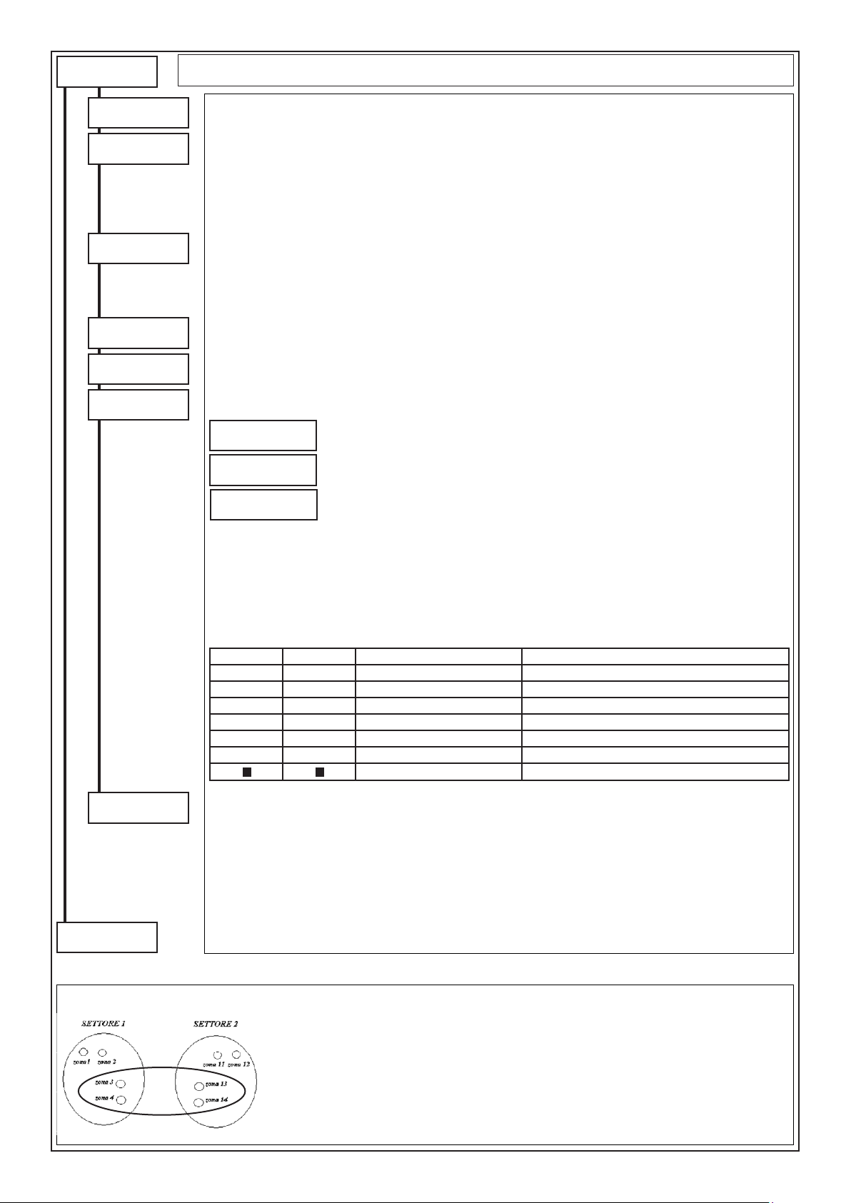
from previus
page
User Codes
Skip part. choose
NO
Patrol tour
NO
Bouble check
NO
Chiave istantan.
NO
Shift # 1
0 (1 .. 15)
Shift # 2
0 (1 .. 15)
Multi-part. vis.
Flat
Skip partition choose: When this option is activated, the user will be able to operate on all his partitions also from
keypads belonging to other partitions (if Master User is in NO).
Patrol Tour: ”YES” enables the code patrol function; the patrol code cannot perform any other operation if not that
of entering its code:
- It cannot perform operations (armings, disarmings, exclusions, OC)
- It cannot access any user menu
Messages: The string “Patrol tour enabled” with the date/time appears when the patrol tour code is entered; the
events “user code xxx” and then “Access Patrol Tour keypad#” are also saved.
At the end of the patrol tour time, the message “deactivate patrol tour” appears and the event is saved in the memory.
Bouble check: “Yes” requires recognition at the keypad of two User Codes congured with this option or the associated
TOYS, within the period of time programmed in the “Partitions” menu.
N.B.: The codes set at “YES” always work with “double consent”.
Chiave istantanea: “Si” abilita i TOY abbinati al codice a lavorare in modalità istantanea indipendentemente dalla
programmazione dei lettori nelle tastiere A500Plus.
Shift 1: This denes in which of the 15 available time bands, programmable using the “Timing Programmer”, the
user code is enabled. With 0 the code is always enabled.
Shift 2: This denes in which of the 15 available time bands, programmable using the “Timing Programmer”, the
user code is enabled. With 0 the code is always enabled.
Multi part. vision: It is possible to vary the displaying of the partitions to which the code is associated, when this is
linked to more partitions.
Partition 1
ko-ap###########
Part.:0203040608
stato:okon
Partition # 03 ok
ofces
--
arpe
Flat: enables the user to display the partitions.
Compact: enables the user to display only the partitions of competence in groups of 5 at a time.
Continous: allows the user to visualise the relative partitions one at a time and the relative
descriptive string.
User label
to following
page
Commands summary:
• [][][][]: to select the partition
• [ENT]: to access the partition
• [CLR]: to directly set the partition number
• [0]: to simultaneously manage all partitions of competence
• [ESC]: to go back by one step
Visualisations
COMPACT FLAT CONTINUA DESCRIZIONE
OK K PARTITION #01 ok system disarmed, zones balanced
- - - PARTITION #01 -- system disarmed, zones open
On O PARTITION #01 On system armed in ON
Ho H PARTITION #01 Ho system armed in HOME
Ar A PARTITION #01 Ar system armed in AREA
Pe P PARTITION #01 Pe system armed in PERIMETER
- Partition not of competence
User label: it is possible to associate a description of 16 alphanumerical digits for every User Code;
Press (CLR) to vary
Writing keys::
(1)abc1 (2)def2 (3)ghi3 (4)jkl4 (5)mno5 (6)pqr6 (7)stu7 (8)vwx8 (9)yz. (0)_’0
Press arrows () and () to position the cursor
Press () or () to move
Press (ENT) to conrm
Press (ESC) to go back
NOTE: After 3 attempts at entering incorrect codes, the control system will be disabled.
NOTE: To guarantee compliance with document T014, the User Code must have 6 gures.
Example: Two Partitions and one PATROL Partition
PARTITION 3
Intends performing patrol that interests zones 3, 4, 13 and 14: the guard can move freely as long as
within the inuence area of these detectors.
To do this, a patrol partition is created, for example number 3, that includes the above-said zones, that
become common. It is now possible to create a patrol user by simply assigning this partition 3 to a user
code and enabling the “PATROL “YES”” step. The moment the patrol user enters the code, the common
zones, associated to partition 3, become inactive, and the surveillance can carry out the inspection. A
timer is also simultaneously activated (different for every available patrol partition), used to automatically
reactivate partition 3 and, eventually, proceed with the communication (and/or alarm) for “patrol not
completed”. At the end of the inspection, the patrol user deactivates the patrol function, and by doing
this, the common zones behave following the arming state relating to the original 1 and 2 partitions.
- 43 -
Page 44

from previus
page
User proles
ENT
User prof. #
1 (1 .. 8)
Memory view
OFF ZONE func.
Buzzer exclusion
Enable User OC
Enable RTC func.
Stop dialler
Code change
Change tel. par.
Immediate disarm
YES
YES
YES
YES
YES
YES
YES
YES
YES
User Proles
User prole: Every User Code can be associated to one of the 32 available proles.
The user proles identify 32 different personalisations to which every user code can refer. The personalisations
consist in the enabling or not of certain keypad functions. The keys that refer to the functions are shown in brackets.
Example: By enabling the “Arms at ON” function, the key (ON) is consequently enabled. If a user code is associated
to this prole, the user will have the possibility of arming at ON.
Memory view - command (MEM): “YES” enables the Code to the possibility of examining the events memory of
the control panel.
OFF ZONE func. - command (ZONES): “YES” enables the Code to the possibility of excluding the zones from
keypad or from RTC with command (0).
Buzzer exclusion: “YES” enables the Code to the possibility of excluding the sound of the buzzer of the keypad.
Enables User OC: “YES” enables the Code to activate the OC outputs from keypad or from RTC using command (6).
Enables RTC fun- (Enables RTC functions) (Remote Telephone Control): “YES” enables the Code to remotely
manage the Control Panel through the PSTN or GSM line.
Stop dialler (interrupts telephone communication): “YES” interrupts the current telephone communications and
those awaiting recognition of the user code (keypad, TOUCH or BIP) and, during a telephone call, pressing key 3
on the phone being called if the user code is associated.
Code change - command (1): “YES” enables the Code to the possibility of varying itself.
Change tel. par. (Changes telephone parameters) - command (1): “YES” enables the Code to the possibility of
varying/checking the telephone parameters:
- Phone numbers with VOCAL or SMS protocol and with user Partitions consistent with those of the phone number
- Check residue credit SIM Card
- Check eld intensity GSM
- Variation SIM Card Expiry Date if the code is Master
Immediate disarm: “YES” enables the Code for the disarming of the control panel, without pressing key (5) from
the keypad (it must, however, be enabled to disarm, see Disarms control panel).
Disarm timer-arm
Timer bypass
Activat. overtime
Date / Time
Zone Walk Test
Test outputs
Enable Install.
Reset re loop
NO
NO
NO
YES
NO
NO
YES
NO
Disarms Timer - arm (disarms with timer active): “YES” enables the Code to the disarming of the control panel,
even if the control panel has been previously armed by the timer. “NO”, the Code does not have the possibility of
disarming the control panel, until the automatic disarming of the timer.
PO inhibition - command 1: By setting “YES” it enables the Code to block the Timer
Activates overtime - command (8): “YES” enables the Code to postpone the arming by one hour, from Timer, for
a maximum of three times (see Timer).
Date/Time - command (1): “YES” enables the Code to the possibility of varying the date and time
Zones walk Test: The zones’ walk test function allows to display the state of all zones for the control panel/keypads/
satellites.
- Key (5), allows to deactivate or activate the memory function. Also, by exiting and entering the MEMO function,
the previous memorisations are deleted.
- Key (CLR), allows exiting from the Zones’ Test function.
- The arrow keys () and () allow selecting the group of zones to be displayed.
- The wording (MEMO) signals that the memorisation modality is active, therefore the unbalancing of one or more
zones, causes the relative memorisation.
Note: for the lines on the keypads the MEMO function is always active and cannot be excluded
Test Outputs: “YES” enables the User Code to carry out a function check of the outputs of the control panel
consisting in their activation for 3 seconds (User Manual).
Enable Installer: Enable the Installer for access to programming through the keyboard, direct connection through
USB port or remote phone connection.
Reset re loop - command (2): “YES” enables the Code to perform the FIRE Alarm Reset (User Manual).
to following
page
Press (CLR) to vary
Press () or () to move
Press (ENT) to conrm
Press (ESC) to go back
- 44 -
Page 45

from previus
page
User Proles
BIP
ENT
Key num. #
1 (1 . . 8)
Operation Type:
Arm. ON Part.
Partition #
1 (1 . . 9 )
Emerg. Key
NO
BEEP: In this menu, it is possible to assign a specic function to each channel of the remote control.
- Key number #: select the number between 1 and 8 of the channel to be programmed
- None: no function associated
- Activates/Deactivates OC?: the key is associated to the activation/deactivation of the O.C. output.
It must be programmed as “Cat. User”.
- Switches OC: varies the state of the O.C. output; activates it if disarmed, deactivates it if armed. It
must be programmed as “Cat. User”.
- Arming ON /HOME /AREA /PERI /Disarming - SECT: ?: the key is associated to the arming/disar-
ming of one or more Partitions; if Partition 65 (sixty-ve) is set, the command works on all Partitions
associated to the user
- Despatch: Panic/Doctor/Fire: the key is associated to the panic/doctor/re signal
- Macro: the key is associated to the arming MACRO function which number is herein programmed
Emergency Channel:
Note: if the emergency option is enabled (YES), the emergency code function will also be activated
simultaneously with the operation associated with the button.
Keys functioning:
Keys from 1 to 4 directly activate the function to which they are associated, the second group of
keys is activated with the simultaneous pressing of key 5 (the middle one) and subsequently of one of
the other keys.
Press (CLR) to vary
Press () or () to move
Enter the key to be set
Press (ENT) to conrm
Label
1 2
5
3 4
PROGRAMMING OF THE CHANNELS ON THE REMOTE CONTROL
Select the Key Function from 1 to 5+4 according to the
Channels
1 • 1
2 • 2
3 • 3
4 • 4
Label: it is possible to associate a description of 16 alphanumerical digits for every User Prole;
Press (CLR) to vary
Writing keys::
(1)abc1 (2)def2 (3)ghi3 (4)jkl4 (5)mno5 (6)pqr6 (7)stu7 (8)vwx8 (9)yz. (0)_’0
Press arrows () and () to position the cursor
Press () or () to move
Press (ENT) to conrm
Press (ESC) to go back
conversion table “Channels - Keys”
Keys to
press
Channels
5 • 5+1
6 • 5+2
7 • 5+3
8 • 5+4
Keys to
press
to following
page
- 45 -
Page 46

from previus
page
Readers
ENT
Arming zones
ENT
Working Mode
Pulse mode
Disarm timer-arm
A500Plus
ENT
Keypad number
1 (1 . . 8)
YES
Readers
Arming Zone
The functioning of the outdoor arming zones is programmed in this Menu for one key electronic board. By accessing
and exiting this menu, all pending armings will be disarmed.
Key functioning mode
• Level mode: when an arming input is balanced with its resistance, the control panel results disarmed; when the
resistance opens or short circuits, the control panel results armed.
Example of armings sum: the arming from keypad and the closing of the arming input cause a sum of the armings,
with the result that, for the control panel to return in disarmed state, the arming clamp must be open and the keypad
disarmed.
ATTENTION: when two armings are summed, the most important one in hierarchical order prevails.
• Pulse mode: the closing and subsequent re-opening of an arming input causes the arming of the control panel in
the relative modality; a new impulse will determine its disarming. With this setting, the control panel can be armed
and disarmed indifferently from keypad or from arming input, without bounds.
Disarms Timer-arm: “With a “YES” the outdoor armings are enabled, for example “Electronic keys”, to disarm the
control panel previously armed from Timer. With a “NO”, to disarm the control panel wait for the automatic disarming
from Timer, or disarm from keypad with a User Code enabled to disarm with Timer active.
CAUTION: using this function voids compliance with EN50131
Reader on A500Plus
Keypad number: selects the keypad A500Plus to be programmed
Command mode
Single
Modo comando:
• Single: when the TOY is brought close to the reader, depending on programming of the associated user code, the
various options - ON, Scenario 1, Scenario 2, and Disarmed - are presented.
- If the keypad is associated to a single Partition, the options presented refer to the single Partition.
- If the keypad is associated to more than one Partition, and there is a “User-TOY” also associated to more than one
Partition, the options presented refer to the total of the Partitions in common between the keypad and the “User-TOY”.
• User code: when the key is neared to the reader, one passes directly to the user menu.
- If the keypad is associated to a Partition, it will directly display the state of the Partition.
- If the keypad is associated to more partitions, it will display the possibility of choosing on which partition to work.
Press (CLR) to vary
Press () or () to move
Press (ENT) to conrm
to following
page
- 46 -
Page 47
from previus
page
Accesses
ENT
TOY on A500P
ENT
TOY #
1 (1 .. 128)
TOY acquisition
ENT
TOY acquisition
........... running
TOY deletion
ENT
TOY deletion
......... executed
All deletion
ENT
Accesses
In this menu it is possible to program the acquisition of the TOYS that will have access to the control panel.
Acquisitions:
The acquisition of the TOYS can be carried out through the A500Plus keypads.
The individual TOYS are memorised in memory locations from 1 to 128. The same is valid for the BIP remote
controls acquired on the radio satellite.
To respect the enablings and the associations of the TOYS/remote controls to the codes, it is fundamental they
are acquired in the two sections, in the same order.
TOY on A500P: Enables to acquire the TOYS using the key block of the A500Plus keypad
TOY: selects the TOY memory locations to be programmed
Acquisition TOY: by accessing this menu the possibility of acquiring the Touch is activated.
Move the TOY towards the RS connector while the display indicates “.... in progress”
Note: if the Touch has already been acquired, the display will show the location where it is memorised.
TOY deletion: by accessing this menu the TOY is deleted.
All deletion: enter this menu to simultaneously cancel all the memorised TOYS
Are you sure...??
CLR=NO ENT=YES
TOY / BIP
ENT
TOY / BIP
1 (0 .. 128)
Assoc. user num.
1 (0 .. 128)
Emerg. code
Key enable
ENT
Keys enable 1
YYYYYYYYYYYYYYYY
Keys en.17..33..49
YYYYYYYYYYYYYYYY
TOY/BIP: Selects the memory location of the TOY/remote control to be programmed
Ass. user num. (associated user number): denes to which user the Touch/BIP must be associated. The key/
remote control acquires the enablings of the prole associated to the user.
Emergency key: with “YES” it denes that the reading of the Touch/BIP will be considered an emergency code.
NO
Enablings: By setting “YES” the Key/remote control is enabled, acquired in a specic memory location (from
1..128), to work.
Press (CLR) to vary
Press () or () to move
Press (ENT) to conrm
to following
page
- 47 -
Page 48

from previus
page
Keypads
ENT
Keypad number
1 (1 .. 8)
Partitions
YYYYYYYY
Buzzer on alarm
Buzzer on exit
Buzzer on entry
Buzzer on chime
Buzzer on door
Beep of keys
Buzz. timer ann.
YES
YES
YES
YES
YES
YES
YES
Keypads
Keypad number: selects the keypad to be programmed
Partitions (controlled Partitions): with (Y) the keypad is associated to the Partition.
The keypad can be associated to work with one or more Partitions.
Buzzer: For every keypad the functioning of the Buzzer can be individually enabled, in case of wanting to hear
the scanning of only the input, of output and of alarm time.
Example:
Keypad 1: Alarm + Output + Return
Keypad 2: Alarm + Return + Timer Warning
Buzzer on alarm: if set at “Yes”, the Buzzer is enabled for the Zone, Tamper, Fire and Anti-mask alarms when
these are enabled in their relative congurations.
Buzzer on exit: if set at “Yes”, during start-up, timed zones are activated, and the Buzzer is activated at a slow
cadence for the duration of the exit time.
Buzzer on entry: if set at “Yes”, and if the activated timed zones are unbalanced, the Buzzer is activated at a fast
cadence for the duration of the entry time.
Buzzer on chime: if set at “Yes”, and if at least one programmed zone like Chime is unbalanced, the Buzzer is
activated and emits a continuous sound.
Buzzer nn door: if set at “Yes”, and if at least one programmed zone like Door is unbalanced, the Buzzer is
activated and emits a continuous sound.
Beep of keys: Enables or not the beep of the keypad upon pressing of the keys;
- If set at NO, the Beep of the keys is always deactivated;
- If set at YES, the enabled user excludes and includes the Beep as it pleases.
Buzzer timer ann.: It is the warning upon automatic inclusion of the timer, which can be enabled or not for every
keypad.
Enable Quick Arm
ENT
Armed ON
Macro A
1 (0 . . 64)
Macro B
2 (0 . . 64)
A500Plus Audio
ENT
A500Plus RTC
Events audio en.
Zones audio en.
OC audio en.
Shift # 1
0 (0 . . 15)
Shift # 2
0 (0 . . 15)
Label
YES
YES
YES
YES
YES
Enable QuickArm: For each keypad it is possible to enable the Quick Arm function for ON, Macro key A and
Macro key B.
Armed ON: Setting to “YES” enables the QuickArm option for ON
Utilizzando questa funzione decade la Conformità alle norme EN50131
Macro A: Select a Macro number to activated in Quick Arm mode with key A.
Uilizzando questa funzione decade la Conformità alle norme EN50131
Macro B: Select a Macro number to activated in Quick Arm mode with key B.
Utilizzando questa funzione decade la Conformità alle norme EN50131
ATTENTION: Activation of the Macros with the Quick Arm function does not turn off the Partition.
A500Plus Audio: the audio of the various events that are communicated can be enabled separately for each keypad.
A500Plus RTC: “YES” enables the Keypad to the possibility of performing the RTC
Events Audio en.: “YES” enables the Keypad to the possibility of activating the communications of the enabled
events
Zones audio en.: “YES” enables the Keypad to the possibility of activating the communications of the inputs
openings
OC Audio en.: “YES” enables the Keypad to the possibility of activating the communications of the activations
/ deactivations of OC outputs
Shift 1: Denes in which of the 15 available shift, that can be programmed by the “Timer”, the A600 keyboard
audio is enabled. If 0 is set, the audio is always enabled.
Shift 1: Denes in which of the 15 available shift, that can be programmed by the “Timer”, the A600 keyboard
audio is enabled. If 0 is set, the audio is always enabled.
Label: it is possible to associate a description of 16 alphanumerical digits for every keypads;
to following
page
Press (CLR) to vary
Writing keys::
(1)abc1 (2)def2 (3)ghi3 (4)jkl4 (5)mno5 (6)pqr6 (7)stu7 (8)vwx8 (9)yz. (0)_’0
Press arrows () and () to position the cursor
Press () or () to move
Press (ENT) to conrm
Press (ESC) to go back
- 48 -
Page 49

from previus
page
A500Plus Audio
ENT
A500Plus Audio
A500Plus Audio: this menu is used to select the events that will be vocally communicated by the A500Plus keyboard.
Partitions
YYYYYYYY
Events to dial
ENT
Watch-Dog
Com. Tamper
Mains fault
Battery
Autotest
Fire Zone
Interference
Sirens failures
ON Arming
HOME Arming
AREA Arming
PERI Arming
Disarmed ON
Disarmed HOME
Disarmed AREA
Disarmed PERI
Zone bypass
Sensor fault
Antimask
Com. codes
Us/Key false
Com. Panic
Com. Medic
Com. Fire
PSTN events
GSM events
to following
page
Partitions (controlled Partitions): (Y) associates the A500Plus audio to the Partition.
The audio can be enabled to work on one or more Partitions.
Events to dial: In this menu the Audio events are associated to the A500Plus:
Watch Dog: Communication of the Watch-Dog
NO
Com. Tamper: Communication of all events of Tamper type
YES
Mancanza rete: Communication of No network voltage after a delay programmable in “Times Programming”.
YES
Battery: Communication of the low level state of the battery
YES
Autotest: Communicates the self-test
NO
FIRE Zone: Communicates the re protection alarm received from the Fire lines
NO
Interference: Communication of radio interference signal.
NO
Sirens failures: Communication of the faults relating to the Buzzers with serial connection
NO
ON Arming: Communication of the Arming in ON modality
YES
HOMEArming: Communication of the Arming in HOME modality
NO
AREA Arming: Communication of the Arming in AREA modality
NO
PERI Arming: Communication of the Arming in PERIMETER modality
NO
Disarmed ON: Communication of the disarming in ON modality
YES
Disarmed HOME: Communication of the disarming in HOME modality
NO
Disarmed AREA: Communication of the disarming in AREA modality
NO
Disarmed PERI: Communication of the disarming in PERIMETER modality.
NO
Zone bypass: Communication of an eventual zone exclusion
NO
Sensor fault: Communication of failure to receive Survival for the radio sensors, Disqualication for the BMHP
NO
barriers and Dirty lenses for the OUTSPIDER sensors.
Antimask: Communication of reporting antimask wireless sensors enabled this feature.
NO
Communicates codes: Communication of the entering of an enabled code
NO
Us. /key false (user/false keys): Communication by a user or reading of a false TOY
NO
Communicates Panic: Communication of the panic message.
NO
Communicates Medic: Communication of the doctor message.
NO
Communicates Fire: Communication of the re message.
NO
PSTN Events: Communicates the no telephone line
NO
GSM Events: Communicates the low SIM Card credit and, if set, also enables the call for GSM self-test
NO
N.B.: if ON/OFF voice communication is enabled, the Partition Sound programming inserts the associated audio
in the voice message of the A500Plus keyboards.
Press (CLR) to vary
Press () or () to move
Press (ENT) to conrm
- 49 -
Page 50

from previus
page
WL/XSATHP satell
ENT
Satellite addr.
1 (1 . . 8)
Sensor modify
ENT
Sens. acquisition
ENT
Sens. acquisition
Sens(n) Sat(n)
signal received
Sensors deletion
ENT
Sensor deletion
1 (max. 32)
All deletion
ENT
Are you sure...??
CLR=NO YES=ENT
Sensors verify
ENT
Sensors list
ENT
Sensors list 1
YYYYYYYYYYYYYYYY
Sensors test
ENT
Sens(n) Sat(n)
signal received
BIP modify
ENT
BIP Acquisition
ENT
Group number
1 (1 . . 4)
Numero gruppo
Sat(n) G(n)TCM(n)
signal received
BIP Deletion
ENT
BIP #
1 (1 . . 64)
All deletion
ENT
Are you sure...??
CLR=NO YES=ENT
BIP verify
ENT
BIP list
ENT
Lista BIP 1
nnnnnnnnnnnnnnnn
BIP test
ENT
Sat(n) G(n) TCM(n)
signal received
Eeprom deletion
ENT
to following
page
WL / XSATHP satellites
WL/XSATHP satellite: By accessing in this menu there is the possibility of programming the sensors via
radio and the sensors addressed performing the acquisition, the deletion and the signal verications for
every acquired sensor.
Note: all references to the detectors are to be considered relating to the address selected on the detector
with the Dip and not to the zone belonging in control panel.
CAUTION: using these peripherals voids compliance with EN50131
Sensor modify: in this menu the acquisition and deletion of the detectors via radio per satellite is programmed.
Satellite addr.(Satellite address): select the satellite on which the acquisition or deletion of the detectors
procedure is to be carried out
Satellite via Radio:
Sens. Acquisition(detectors acquisition): by accessing this menu the acknowledgement procedure of the
various detectors activates for 60 seconds.
Sens(n) Sat(n)(sensor num.; satellite num.): these are the references for understanding which satellite via
radio has received, which detector has transmitted and to which control panel zone it is coupled.
Signal received: the amount of signal received from the sat-radio is highlighted on a bar from 1 to 8.
Sensor deletion (detectors deletion): by accessing this menu there is the possibility of individually deleting
the various acquired detectors.
All deletion: by accessing this menu there is the possibility of simultaneously deleting all acquired detectors.
Once deletion is completed, the display visualises “executed”.
Satellite XSATHP:
Detector memorization : get into this menu to activate for a period of 1 minute the learning process of
sensors connected to the selected satellite. After this period, the keyboard will intermittently the type of
sensor connected to the satellite and its corresponding address.
Sn (n) (detector number) Sat (N) (satellite number) Outspider / BMHP / XSATMINI (sensor type): This is
the way to identify which sensors have been memorized, on which satellite and detector type.
Detector Elimination: not supported function
Total elimination (elimination of all detectors): not supported function
NB: to make the elimination of one or more detectors, disconnect the sensor to remove from its serial port,
and then perform the detector memorization again.
Sensors verify: in this menu there is the possibility of checking which detectors have been effectively
acquired by the satellite via radio and test them.
Sensors list: the acquired detectors are highlighted with a (Y)
Sensors test: checks which satellite via radio has received, which detector has transmitted and to which
control panel zone this is coupled. For XSATHP satellites, such as occurs sensors were acquired, from
which the satellite and the sensor type.
Satellite via Radio: Sens(n) (Sensor num.) Sat(n) (Satellite num.) Signal received (signal quality): see
“Sens. Acquisition”
Note: to include a pad of virtual signal, press (CLR) once. The pad will be active only during the test, not
during the normal functioning of the system. In keypad, as well as the visualisation Sat(n) Dt(n) Zn(n), an
“A” will appear
Note: to activate the memorisation of the radio detectors, press the MEM key in “detectors test” modality.
This function displays a list of detectors received with valid power level.
To exit memorisation, press MEM.
Satellite XSATHP: Sn(n) (Sensor num.) Sat(n) (Satellite num.) Outspider/BMHP/XSATMINI (Sensor
type): see “Sens. Acquisition”
ATTENTION
Programming steps corresponding to the BIP remote control and EEPROM cancellation are active
only for programming the radio satellite. The submenus are also present in the XSATHP satellite
menu but are not programmable.
Remote Controls Acquisition
It is possible to acquire up to sixteen (16) remote controls for every group (max. 4) that must be coded
following the table attached to BIP. It is not possible to acquire more remote controls with the same coding
in the same group and we recommend not acquiring the same remote control on more groups.
To acquire a remote control, transmit from near the receiver, bearing in mind that the ACQUISITION happens
by pressing any key, with the exception of key (5).
Amends Remote Controls: the acquisition and deletion of the remote controls is programmed in this menu.
Satellite add.(Satellite address): select the satellite on which the acquisition or deletion procedure is to
be carried out.
Delete Eeprom: by accessing this menu there is the possibility of simultaneously deleting all acquired
detectors and remote controls. Once deletion is completed, the display visualises “performed”.
Press (CLR) to vary
Write the number to be set
Press () and () to move
Press (ENT) to conrm
- 50 -
Page 51

from previus
page
Sirens
ENT
Siren add.
1 (1 .. 8)
STC command
ENT
O.C. activ. time
Inactive
Partitions
YYYYYYYY
Alarm
Rebalancing
Bypass
Unbalancing
Tamper
AntiMask
Mains Fault
Pwr supply fail
Low Battery
Batt. Unconnected
Battery fail
Tel. line fault
Dialler on-line
OC on Ring
User
User access
Fire
Reset Fire
Timer
Autotest
ON Arming
HOME Arming
AREA Arming
to following
page
Sirens
Siren address: in this menu it is possible to program the parameters of the Buzzers with serial connection.
STC command: in this menu it is possible to personalise operation of the red LED and the sound of the Buzzer
according to the functions associated with this command
TIMES MANAGEMENT Inactive: the output does not activate;
“Times” Note: the set values may be automatically rounded off after conrmation with (ENT)
Partition: Select one or more Partitions to which the STC command of the selected Buzzer is to be associated, and this is
automatically associated to all the zones of the Partitions set at Yes. For the events of a single zone or a set of targeted zones,
it is necessary to leave everything at NO and to associate the O.C. to the single zones of reference.
Alarm: it activates with at least one of the associated zones in alarm state
NO
Rebalancing: it activates with the balancing of all the associated zones
NO
Bypass: it activates with the exclusion of at least one of the associated zones
NO
Unbalancing: it activates with the unbalancing of at least one of the associated zones
NO
Tamper: it activates with the tamper of at least one of the associated zones
NO
Antimask: it activates with the antimasking of at least one of the associated zones
NO
Mains power failure: with “YES”, it activates when the control panel or the supervised power units connected in
NO
series are not powered, after a delay programmable in minutes. (see “Times”)
Power supply failure: with “YES”, it activates when the voltage supplied by the power unit of the control panel
NO
or by that of the supervised power units connected in series is higher than 16 V = or when it is lower than the
voltage generated by the battery or when the output voltage on the various board positives is lower than 10 V =
Low Battery: with “YES”, it activates when the battery of the control panel or of one of the supervised power units
NO
connected in series drops below 10.5 V and there is no charging voltage. It resets when voltage rises above 12.8 V =
Battery Unconnected: with “YES”, it activates when the battery of the control panel or of one of the supervised
NO
power units connected in series, drops below 3 V =
Battery fail: with “YES”, it activates when the battery of the control panel or of one of the supervised power units
NO
connected in series, drops below 9.5 V =
Telephone line fault: with “YES”, it activates when the presence of the telephone line is no longer detected
NO
Dialler on-line: with “YES”, it activates when a telephone communication is in progress
NO
OC on Ring: by setting “YES”, it activates when the control panel receives a GSM call from a phone number
NO
enabled to perform the function.
User: it activates from RTC, from Keypad entering a user code with “User OC Enab.” enabled, from Timer or
NO
from RING.
User access: by setting “YES”, it activates when the associated User Code is entered (see User Proles)
NO
Fire: it activates when there is a FIRE alarm coming from one of the satellites.
NO
Reset Fire: Activated when an enabled user performs a “Reset Fire Line” operation (pressing key 2 in the “User
NO
Menu” ). If the time is set as Bistable, the output is activated for 15 seconds..
Timer: it activates when the Timer reaches the pre-xed day and time; it cannot be controlled by the user.
NO
Autotest: Activated when the central control unit performs the “Autotest” function.
NO
If the time is set as Bistable, the output is activated for 3 seconds.
ON Arming: by setting “YES”, it activates when the Partition is armed in ON
NO
HOME Arming: by setting “YES”, it activates when the Partition is armed in HOME
NO
AREA Arming: by setting “YES”, it activates when the Partition is armed in AREA
NO
Press (CLR) to vary
Press (ENT) to conrm
Press () or () to move
Press (ESC) to go back
Bistable: the output follows the state of the associated function
MM:SS: the output will activate for the set time (MM = Minutes / SS = Seconds)
HH:MM: the output will activate for the set time (HH = Hours / MM = Minutes)
GG:HH: the output will activate for the set time (GG = Days / HH = Hours)
- 51 -
Page 52

from previus
page
PERI Arming
Disarmed
Normally active
Blinking
OC audio en.
O.C. Label
LED Command
ENT
O.C. activ. time
Inactive
Partitions
YYYYYYYY
Alarm
Rebalancing
Bypass
Unbalancing
Tamper
AntiMask
Mains Fault
Pwr supply fail
Low Battery
Batt. Unconnected
Battery fail
Tel. line fault
Dialler on-line
OC on Ring
User
User access
Fire
to following
page
Sirens
PERI Arming: by setting “YES”, it activates when the Partition is armed in PERIMETRO
NO
Disarmed: by setting “Yes”. It is activated when it is DISARMED, or when the PATROL TOUR TIME ELAPSES.
NO
(using the patrol tour function; it signals the failure to enter the patrol tour code within the programmed partition
(“patrol tour time”) reactivation time.
Normally active: set to NO the output supplies a transistorized negative when activated. Set to YES, the output
NO
usually supplies a transistorized negative which is lost when activated.
Blinking: by setting “Yes”, it ashes for the time it is active.
NO
OC audio enabled: by setting “YES” the variation of the state of the O.C. output is vocally communicated
NO
O.C. label: it is possible to associate a description of 16 alphanumerical digits for every open collector;
Press (CLR) to vary
Writing keys::
(1)abc1 (2)def2 (3)ghi3 (4)jkl4 (5)mno5 (6)pqr6 (7)stu7 (8)vwx8 (9)yz. (0)_’0
Press arrows () and () to position the cursor
Press (ENT) to conrm
Press (ESC) to go back
LED Command: in this menu it is possible to personalise operation of the red LED or green LED and the sound
of the Buzzer according to the functions associated with this command
TIMES MANAGEMENT Inactive: the output does not activate;
“Times” Note: the set values may be automatically rounded off after conrmation with (ENT)
Partition: Select one or more Partitions to which the LED command of the selected Buzzer is to be associated, and this is
automatically associated to all the zones of the Partitions set at Yes. For the events of a single zone or a set of targeted zones, it
is necessary to leave everything at NO and to associate the O.C. with the single zones of reference.
Alarm: it activates with at least one of the associated zones in alarm state
NO
Rebalancing: it activates with the balancing of all the associated zones
NO
Bypass: it activates with the exclusion of at least one of the associated zones
NO
Unbalancing: it activates with the unbalancing of at least one of the associated zones
NO
Tamper: it activates with the tamper of at least one of the associated zones
NO
Antimask: it activates with the antimasking of at least one of the associated zones
NO
Mains power failure: with “YES”, it activates when the control panel or the supervised power units connected in
NO
series are not powered, after a delay programmable in minutes. (see “Times”)
Power supply failure: with “YES”, it activates when the voltage supplied by the power unit of the control panel or
NO
by that of the supervised power units connected in series is higher than 16 V = or when it is lower than the voltage
generated by the battery or when the output voltage on the various board positives is lower than 10 V =
Low Battery: with “YES”, it activates when the battery of the control panel or of one of the supervised power units
NO
connected in series drops below 10.5 V and there is no charging voltage. It resets when voltage rises above 12.8 V =
Battery Unconnected: with “YES”, it activates when the battery of the control panel or of one of the supervised
NO
power units connected in series, drops below 3 V =
Battery fail: with “YES”, it activates when the battery of the control panel or of one of the supervised power units
NO
connected in series, drops below 9.5 V =
Telephone line fault: with “YES”, it activates when the presence of the telephone line is no longer detected
NO
Dialler on-line: with “YES”, it activates when a telephone communication is in progress
NO
OC on Ring: by setting “YES”, it activates when the control panel receives a GSM call from a phone number
NO
enabled to perform the function.
User: it activates from RTC, from Keypad entering a user code with “User OC Enab.” enabled, from Timer or from
NO
RING.
User access: by setting “YES”, it activates when the associated User Code is entered (see User Proles)
NO
Fire: it activates when there is a FIRE alarm coming from one of the satellites.
NO
Press (CLR) to vary
Press (ENT) to conrm
Press () or () to move
Press (ESC) to go back
Bistable: the output follows the state of the associated function
MM:SS: the output will activate for the set time (MM = Minutes / SS = Seconds)
HH:MM: the output will activate for the set time (HH = Hours / MM = Minutes)
GG:HH: the output will activate for the set time (GG = Days / HH = Hours)
- 52 -
Page 53
from previus
page
Sirens
Reset Fire
Timer
Autotest
ON Arming
HOME Arming
AREA Arming
PERI Arming
Disarmed
Normally active
Blinking
OC audio en.
O.C. Label
Parameters
ENT
Alarms counter
Max 5 in 24h
Princ. sound tone
1 (1 . . 8)
Alt. sound tone
2 (1 . . 8)
Flash
Follows alm. st.
STC Command
Red Led = STC
Tamper enable
ENT
Antifoam
Temperature
Vibration
LED Command
Green Led = LED
to following
page
NO
NO
NO
NO
NO
NO
NO
NO
NO
NO
NO
Reset Fire: Activated when an enabled user performs a “Reset Fire Line” operation (pressing key 2 in the “User
Menu” ). If the time is set as Bistable, the output is activated for 15 seconds..
Timer: it activates when the Timer reaches the pre-xed day and time; it cannot be controlled by the user.
Autotest: Activated when the central control unit performs the “Autotest” function.
If the time is set as Bistable, the output is activated for 3 seconds.
ON Arming: by setting “YES”, it activates when the Partition is armed in ON
HOME Arming: by setting “YES”, it activates when the Partition is armed in HOME
AREA Arming: by setting “YES”, it activates when the Partition is armed in AREA
PERI Arming: by setting “YES”, it activates when the Partition is armed in PERIMETRO
Disarmed: by setting “YES”, it is activated when it is DISARMED, or when the PATROL TOUR TIME ELAPSES.
(using the patrol tour function; this signals that the patrol code is not entered within the programmed partition
(“patrol tour time”) reactivation time)
Normally active: set to NO the output supplies a transistorized negative when activated. Set to YES, the output
usually supplies a transistorized negative which is lost when activated.
Blinking: by setting “YES”, it ashes for the time it is active
OC audio enabled: by setting “YES” the variation of the state of the O.C. output is vocally communicated
O.C. label: it is possible to associate a description of 16 alphanumerical digits for every open collector;
Press (CLR) to vary
Writing keys::
(1)abc1 (2)def2 (3)ghi3 (4)jkl4 (5)mno5 (6)pqr6 (7)stu7 (8)vwx8 (9)yz. (0)_’0
Press arrows () and () to position the cursor
Press (ENT) to conrm
Press (ESC) to go back
Parameters: in this menu it is possible to personalise the work parameters of the Buzzer
Alarm counter:
Pricipal sound tone: it is possible to select one of 8 tones for the Principal Sound
Alternative sound tone: it is possible to select one of 8 tones for the Alternative Sound
Flash: Follows alarm state: the Flash is restored at the rebalancing of the input that has generated the alarm
STC restore: the Flash is deactivated when the STC input is rebalanced
STC Command:
Tamper enable:
unit with serial connection are enabled.
Antifoam: set at “Yes”, enables control of the Antifoam sensor of the Buzzer, when applicable
NO
Temperature: set at “Yes”, enables control of the Temperature sensor of the Buzzer
YES
Vibration: by setting “Yes”, control of the Vibration sensor of the Buzzer is enabled
YES
LED Command:
Press (CLR) to vary
Press (ENT) to conrm
Press () or () to move
Press (ESC) to go back
Max 5 in 24h: the siren blocks the functioning of the Cone and the Flash in rest status after 5
alarms inwithin 24 hours and unblocks it after 24 hours from the first alarm.
Unlimited: the siren does not perform any blocking
40 min./STC restore: the Flash automatically deactivates after approximately 40 minutes or when the
STC input is rebalanced
Red Led = STC: the RED LED is activated at the unbalancing of the STC input and is
deactivated at the rebalancing of the STC input
St. chg = 1 Beep: a BEEP signals both the unbalancing and the rebalancing of the STC input
St.c. = 1 B.+Red L.: the unbalancing of the STC input activates a BEEP and the RED LED, the
rebalancing of the STC input activates a BEEP and deactivates the RED LED
Beep only-No led: RED LED and BEEP are not activated by the unbalancing of the STC input
In this step, the tampers to activate or otherwise the T T output and signalling to the central control
Green Led = LED: the unbalancing of the LED input activates the GREEN LED, the rebalancing of
the LED input deactivates the GREEN LED
Only alt. sound: the unbalancing of the LED input activates the alarm with the Alternative Sound and
the Flash. The rebalancing deactivates the Sound while the Flash behaves based on its configuration.
Alt.sn. + Gr. Led: simultaneously executes the actions of Value 1 and 2
Unbal. = memo STC: the unbalancing of the LED input activates the visualisation of the STC input
status with the RED LEDs
- 53 -
Page 54

from previus
page
Sirens
Sound level
1 (1 . . 8)
Max time alarm
3 (1 . . 8)
R & G Led pulses
Status
Sound level: there is a choice of 8 tones.
Alternative Sound. 1 is the Maximum and 8 is the Minimum.
Max time alarm (minutes):
R & G Led pulses: The value set is relative to both the functioning of the Red LED and that for the Green LED:
Press (CLR) to vary
Press (ENT) to conrm
Press () or () to move
Press (ESC) to go back
The values are relative to the sound level of both the Main Sound and the Alternative Sound
Status: the LEDs are activated with fixed light at the unbalancing of the relative input and
deactivated at the rebalancing of the relative input
Follows Flash: the LEDs are activated with a cadence similar to that of the FLASH at the
unbalancing of the relative input and deactivated at the rebalancing of the relative input
5 fast pulses: the LEDs emit 5 quick flashes at the unbalancing of the relative input and de-
activated at the rebalancing of the relative input
1 pulse: the LEDs are activated with fixed light for approximately one second at the unbalancing
of the relative input and remain inhibited at the rebalancing of the relative input
Unb = 5fp. Bal = 1p.: the LEDs emit 5 quick flashes at the unbalancing of the relative input
and are activated with a fixed light for approximately one second at the rebalancing of the
relative input
R=blnk+Fl. V=st.:the Red LED emit quick flashes at the unbalancing of the relative input and
slowly at the rebalancing ; the FLASH emit few quick flashes at the unbalancing of STC and
one slowly at the rebalancing; the Green LED is a “STATUS”
The values are relative to the sound level of both the Main Sound and the
to following
page
- 54 -
Page 55

from previus
page
In this menu it is possible to memorise up to 16 telephone numbers. For every telephone number, it is possible to dene the communication
protocol (Vocal, Fast, Sia 1st lev., Sia 2nd lev., Sia_Hayes, Contact-Id), the number of call attempts for every Tel. Num., with which interface
(PSTN/GSM) the calls are forwarded and if the main, the Partition and the additional phone must be communicated (for vocal protocols).
Small programming steps:
- Set existence of the telephone in the installation menu; PSTN ENABLING: YES and/or GSM ENABLING: YES
- Set a communication protocol; ex: VOCAL
- Set a telephone number to call; in “telephone number” - ex: 049 9698 ...
- Set the communication interface: ex PSTN if using the telephone integrated on telephone line, GSM if using module Xgsm.
- Associate a user to the set telephone number to give the number the user features (RTC - Calls block - Number recognition); leave 0
(zero) if no association is wanted.
- Associate the zones that will have to be communicated to the telephone number. - ZONES
- Associate the technical events that will have to be communicated to the telephone number. - ASSOCIATE EVENTS
- Associate the telephone numbers to the active Partitions. - “ASSOCIATE PARTITIONS”
Denition of “interface”: physical mean with which a call is made.
Denition of “protocol”: information distribution modality
Dialler
Dialler
ENT
Teleph. numbers
ENT
Tel. num. #
1 (1 .. 16)
Tel. num. #
Email
Protocol
VOCAL
Telephone numbers
Telephone number: Select the telephone number to be programmed from 1 to 16.
Telephone Number 1: Set the wanted telephone number
The letter P on PSTN interface ensures that the dialler interprets the number before this initial as necessary for
getting an external line from a switchboard (Ex.: 9P049W334312).
The letter W introduces a three seconds pause where it has been included (Ex.: 049W334312).
The listening of the free line tone, if enabled, starts after selection of part of the number before the P code.
If the interface in use is GSM, all digits before the symbols P and W, are omitted from the selection.
Note: The letters P and W, are set by scrolling with the arrows () and () and by conrming the data by pressing
the arrow ()
Email: Set the email address to send the messages to. Requires both the EWEB/EWEB WIFI optional board to be
installed and the WEB interface to be set.
Protocol: denes, for every telephone prole, the modality with which the events must be transmitted.
- VOCAL: it is the protocol that is normally used to communicate the alarm messages in vocal.
- FAST FORMAT: this is a protocol that allows alarm and technical events to be communicated to special receivers
installed at Security Firm headquarters
- SIA1: this is a protocol that allows alarm and technical events to be communicated to special receivers installed
at Security Firms, more advanced compared to the FAST FORMAT.
- SIA2: this is a protocol that allows alarm and technical events to be communicated to special receivers installed
at Security Firms, more advanced compared to the FAST FORMAT.
- SIA-HAYES: it is a more advanced protocol than SIA that allows alarm and technical events to be communicated
to an AVS-certied modem connected to a PC on which the WINREC. reception software is installed.
- CONTACT-ID: this is a protocol that allows alarm and technical events to be communicated to special receivers
installed at Security Firms, more advanced compared to the FAST FORMAT.
- SMS/Email: this is the protocol that allows alarm or technical events to be communicated either via SMS (in this
case it requires both the optional XGSM board to be installed and the GSM interface to be set) or via email (in
this case it requires the optional XWEB/EWEB board to be installed and the WEB interface to be set).
Interface
PSTN
to following
page
Interface: Set the wanted interface towards which the calls are to be forwarded
- PSTN: Select PSTN if wanting to forward calls only on analogical line
- GSM: Select GSM if wanting to forward the call only on GSM channel using the Xgsm.
- PSTN/ backup GSM: Select PSTN/ backup GSM if wanting to forward the call on PSTN line and use the GSM
channel only if the analogical line is absent.
The switching to GSM happens after verication of the absence of line voltage and/or analysis of the Dial tone
(only if “Free line listening at YES” is set).
Note: the call will be repeated in GSM if the same has not had a good result in PSTN.
- PSTN + GSM: Select PSTN + GSM if wanting to forward the call on both analogical line and on GSM channel
- GPRS/IP: Select GPRS/IP if wanting to forward the call on the GSM line to a receiver set to the SIA - IP protocol
(supports protocols SIA1, SIA2 and CONTACT ID)
- WEB: Select WEB to send the call via the IP network to a receiver that is compatible with the SIA - IP protocol
supports SIA1, SIA2 and CONTACT ID protocols) or to communicate events via email.
Press (CLR) to vary
Press (ENT) to conrm
Press () or () to move
Press (ESC) to go back
- 55 -
Page 56

from previus
page
Telephone numbers
Account code
ENT
Partition #
1 (1 .. 8)
Account code
0 0 0 0 0 0
Associate part.
Present. speech
0 (0 .. 415)
Partition speech
0 (0 .. 415)
Says part. number
Attempts number
3 (1 .. 16)
User #
1 (1 .. 128)
Account code: in this menu, the telephone numbers are associated to the active sectors. Each telephone
number can be associated to one or more partitions.
Partition # : select the Partition to program
Account code (Only showed with the DIGITAL protocol): the digital communications must communicate
the Account Code (Client Code). Therefore, every telephone number, for every Partition, can have its own
Account Code.
• In SiA 1, SiA 2 and SiA_HASi the code is made of 6 digits;
• In FAST FORMAT and CONTACT ID the code is made of 4 digits;;
Customizing vocal announcementl to introduce (Only showed with the VOCAL protocol): introducing a value
different from zero (0) in the “WORD” programming menu, it is possible to activate the vocal announcement
of the plant introducing message.
Associate partition: by setting “YES”, by setting “YES”, voice communication of the events relating to the
partition is enabled
NO
Presentation speech: introducing a value different from zero (0) will communicate the associated word (see
word table).
Partition speech: introducing a value different from zero (0) will communicate the associated word (see word
table), linked to the associated partition.
Says PARITION number: choosing “YES” will communicate “Partition number” words.
NO
Attempts number (of telephone number calls): Communication is repeated for the number of times set. It
is clear that if the communication should have positive result, the attempts will not repeat. With regard to the
Vocal protocol, the control identifying the good result of the call is enabled through the “Listen Reply” option, if
the “Listen Reply” option should be disabled the dialler will perform as many calls as the set attempts.
If all call attempts should fail systematically for more times consecutively, a warning message will be displayed
in keypad: “failed calls”
It is possible to interrupt the call to ones’ own telephone number by pressing key “4” on the telephone receiving
the message or it is possible to interrupt the full cycle of calls by pressing key “3” on the telephone receiving the
message, if the telephone number is associated to a User enabled for “interruption of the telephone communication”;
User: It is possible to associate the telephone number to a certain User to give the number the user features.
This association enables the called user to have the enablings dictated by its prole of reference (ex: RTC -
Calls block - Number recognition).
The association of the telephone number to the user also allows, if enabled, to enter in RTC telephone on GSM
channel directly upon recognition of the incoming number without requesting the code.
The calls interruption or input in RTC commands following a call from the control panel, will be subordinate
N.B.: To enter the Account code, use buttons 0 to 9 for the numbers and buttons UP (ON) and
DOWN (HO) for letters A, B, C, D, E, F.
N.B.: The Partition speech programming inserts the associated sound in the voice message of
the A500Plus keyboards if on/off voice communication is enabled
Enable RTC func.
YES
Stop dialler
YES
Zones
YYYYYYYYYYYYYYYY
Events to dial
ENT
Watch-Dog
Com. Tamper
Mains fault
to following
page
YES
YES
YES
Zones: In this menu the alarm zones are associated to the telephone number.
In this way, the individual alarm and/or zone tamper can be communicated to the programmed telephone
number, if this is set at “YES” in the menu: memorise alarm. The zone reset is communicated if the menu:
memorise reset is set at “YES”.
ATTENTION: it is necessary to associate the telephone number to one or more sectors to ensure that the
control panel can call in case of zones alarm. The control panel will communicate to the telephone number
the sector zones associated to the telephone number.
Technical messages: the authorizations are automatic from the “EVENTS ASSOCIATION” submenu by the
phone numbers’ association and by the “SECTOR ASSOCIATION” submenu. From this very submenu, it is
possible to do it for the digital communication thanks to the association of the account code or vocally thanks
to the vocal message customization.
Events to dial: The events to be sent to the telephone number are associated in this menu
Watch Dog: Watch-Dog means a particular control function on the microprocessor; in cases of serious electrical disturbances
(lightning, sudden voltage changes, etc.) this circuit causes a “restart” of the system without loosing any recorded data.
Com. Tamper: Communication of all events of Tamper type, to the associated telephone number; If associated
to a vocal protocol, the following message will be sent: “Tamper Alarm”
N.B.: By setting NO, the unit no longer complies with EN50131.
Mains fault: Communication of the No network voltage to the associated number, after a delay programmable
in “Times Programming”.
Press (CLR) to vary
Press (ENT) to conrm
Press () or () to move
Press (ESC) to go back
- 56 -
Page 57

from previus
page
Telephone numbers
Battery
YES
Autotest
Fire Zone
Interference
ON Arming
YES
HOME Arming
AREA Arming
PERI Arming
Disarmed ON
YES
Disarmed HOME
Disarmed AREA
Disarmed PERI
Zone bypass
Sensor fault
Antimask
Sirens failures
Com. codes
Emerg. codes
Us/Key false
Com. Panic
Com. Medic
Com. Fire
PSTN events
GSM events
Battery: Communication of the low level state of the battery
Autotest: Communicates the self-test
NO
FIRE Zone: Communicates the re protection alarm received from the Fire lines
NO
Interference: Communication of radio interference signal.
NO
ON Arming: Communication of the Arming in ON modality
HOMEArming: Communication of the Arming in HOME modality
NO
AREA Arming: Communication of the Arming in AREA modality
NO
PERI Arming: Communication of the Arming in PERIMETER modality
NO
Disarmed ON: Communication of the disarming in ON modality
Disarmed HOME: Communication of the disarming in HOME modality
NO
Disarmed AREA: Communication of the disarming in AREA modality
NO
Disarmed PERI: Communication of the disarming in PERIMETER modality.
NO
Zone bypass (NO FAST): Communication of an eventual zone exclusion
NO
Sensor fault (NO FAST): Communication of failure to receive Survival for the radio sensors, Disqualication
for the BMHP barriers and Dirty lenses for the OUTSPIDER sensors.
NO
Antimask (NO FAST): Communication of reporting antimask wireless sensors enabled this feature.
NO
Sirens failures (NO FAST): Communication of the faults relating to the Buzzers with serial connection
NO
Communicates codes (NO FAST): Communication of the entering of an enabled code
NO
Emergency code (NO FAST) - No entering of PATROL code: Communication to the associated number
NO
when an enabled Emergency Code has been entered on the keypad Only for the Partitons dened PATROL,
communicates the “No entering of patrol code” if it sets the “manual rearming at YES”, to the associated number.
Us. /key false (user/false keys) (NO FAST): Communication by a user or reading of a false TOY
NO
Communicates Panic (NO FAST): By keeping key (CLR) pressed, followed by (1) in keypad or pressing keys
A/B/C/D followed by (ENT) if suitably programmed, a silent panic emergency call is generated
NO
Communicates Medic (NO FAST): By keeping key (CLR) pressed, followed by (3) in keypad or pressing keys
A/B/C/D followed by (ENT) if suitably programmed, a medic emergency call is generated.
NO
Communicates Fire (NO FAST): By keeping key (CLR) pressed, followed by (2) in keypad or pressing keys
A/B/C/D followed by (ENT) if suitably programmed, a re emergency call is generated.
NO
PSTN Events (NO FAST): Communicates the cutting/resetting of the telephone line
NO
GSM Events (NO FAST): Communicates the low and out SIM Card credit
NO
N.B.: (NO FAST) indicates the events that are not communicated using the FAST protocol.
Label
to following
page
Label: it is possible to associate a description of 16 alphanumerical digits for every telephone number;
Press (CLR) to vary
Press (ENT) to conrm
Press () or () to move
Press (ESC) to go back
- 57 -
Page 58
from previus
page
Dialler
Teleph. options
ENT
Dial tone listen
Answer listening
Autoansw. machine
Dload w/o callb
Attempts pause
60 (0:255 sec)
Vocal repetition
2 (0 .. 16)
Num. rings answer
0 (0 .. 16)
Slow DTMF dial
Stop dig. calls
Enab. RTC by GSM
SMS limiter
0 (0 .. 255)
YES
YES
NO
NO
NO
NO
NO
Telephone options
Dial tone listen: ree line tone detection circuit is present inside the telephone; when the line is engaged, it ensures
that the dialling happens only when this is effectively present. In case the detecting of the line tone should be
difcult, like in cases of extensions from switchboards, by choosing the option “NO” the free line tone listening
circuit is enabled, favouring the dialling.
The disabling of the free line tone listening circuit makes the analysis of the presence, or not, of the telephone
line less reliable and this may jeopardise the switching of the calls on the GSM channel of the control panel.
Answer listening: If this function is enabled, the vocal message starts to be transmitted only after the called
User has answered; in this case, the call is considered as “completed with success”, therefore, it will not be
repeated to the set number if the rst repetitive cycle is at least heard, or the call is voluntarily interrupted by the
user by pressing key “4” or key 3 from the telephone receiving the message.
By not enabling this function, the message will start as soon as the dialler will have stopped dialling the telephone number
and the vocal calls will be repeated for all “number of attempts” programmed for all entered numbers (see “Attempts “)
N.B.: By setting NO, the unit no longer complies with EN50131.
Autoanswer machine: Should an answering machine be included, the overlapping can be activated (see “RTC
Function”).
Download w/o callb: If this function is enabled, the control panel accepts the remote re-programming directly
without recalling towards the PC.
Attempts pause: Should the calls not be completed successfully, the delay programmed here will be interposed
between the second attempt and every subsequent attempt towards the same telephone number.
It must be noted that, according to regulation, a minimum pause of 6 seconds is automatically inserted between successive calls.
Vocal repetition: It denes how many times the eventual vocal message must be repeated when a telephone
communication is activated.
In case of wanting to communicate the message to a xed or mobile answering machine, we recommend setting
a sufcient number of repetitions, such to guarantee the recording of the message on the answering machine.
Num.rings answer: By enabling the Reply Rings function with a number of rings greater than 0, it is possible
to call the system where the control panel is installed to obtain an RTC connection (see “User RTC Functions”).
Slow DTMF dial: By enabling the Slow DTMF numeration function, the slow composition of the tones of the
telephone numbers called is activated.
Stop dig. calls: Enabling the function, after a successful telephone call to a digital number the central control unit
blocks further calls to the other digital numbers memorised with the same protocol.
Enable RTC by GSM: By enabling this function, the system responds in the GSM channel after 3 rings
SMS limiter: Denes maximum number of SMS to be sent in an interval of 1 hour. By entering 0 it is disabled,
otherwise the control panel sends maximum that number of SMS in one hour and then memorises an event of
“STOP SMS LIMIT N.”. Starts sending again after an hour has passed from the sending of the rst SMS of the series.
XGSM
ENT
PIN
0000
SIM credit ctrl.
GPRS
ENT
APN
ENT
APN
Username
Password
to following
page
YES
Press (CLR) to vary
Enter the telephone number
Press () and () to move
Press (ENT) to conrm
XGSM
PIN: Enter the valid PIN code of the SIM card.
If the PIN code has been disabled this parameter is ignored.
SIM Credit ctrl: If this function is enabled, the control panel will check the credit of the SIM Card. Should a
rechargeable card be installed, leave “NO”.
GPRS: The parameters for data connection via XGSM are programmed in this menu
APN (Access Point Name): Name of the access point (server) to which a mobile device will try to connect to
gain access to the Internet to make data transfers.
APN: Access point name. If left blank, the panel will use the default names made available by the network
operator used (valid only for Italy): TIM: ibox.tim.it, VODAFONE: web.omnitel.it, WIND: internet.wind
Username: user name for accessing the APN (if required by the operator)
Password: password for accessing the APN (if required by the operator)
Press (CLR) to vary Writing keys:(1)abc1 (2)def2 (3)ghi3 (4)jkl4 (5)mno5 (6)pqr6 (7)stu7 (8)vwx8 (9)yz. (0)_’0
Press (ENT) to conrm Press arrows () and () to position the cursor
Press (ESC) to go back Press () and () to move
- 58 -
Page 59
from previus
page
Dialler
XGSM
Credit req. pers.
ENT
Credit tel. num.
Use SMS Credit
Credit SMS
XGSM485
ENT
Tamper commun.
Tamper rst. comm.
PSTN on XGSM485
SIM B available
Cont. dialtone
Num. rings answer
0 (0 . . 16)
SIM A
ENT
PIN
0000
SIM credit ctrl.
GPRS
ENT
YES
NO
NO
NO
NO
Credit request personalization: In this menu, it is possible to personalize the credit request method, in the case
of variation by the operator. The control panel is programmed for the request by the following operators:
Vodafone > call number = 404 TIM > SMS = PRE CRE SIN \ SMS calling number = 40916
WIND > SMS = SALDO \ SMS calling number = 4155
DO NOT USE THE FOLLOWING ACTION IF THE REQUEST PROCEDURE MATCHES THE ONE ALREADY PROGRAMMED.
Credit telephone number: Introduce the operator phone number to be used by the control panel for calling/
forwarding the SMS
Use SMS Credit: Activating this function, the control panel send the indicated SMS in “Credit SMS” for the credit
NO
request. Placing NO, the control panel will ring only once at the phone number indicated in “Credit phone number”.
Credit SMS: In this menu, it is possible to personalize the credit SMS message, as required by the GMS operator.
Press (CLR) to vary
Enter the telephone number
Press () and () to move
Press (ENT) to conrm
XGSM485
The XGSM485 can contain two SIM Cards. If both SIM Cards are installed, at the rst power feed, by default the
operation starts with the Main SIM Card (SIM Card A) and there is an automatic changeover to the Secondary
SIM Card (SIM Card B). This is controlled by the following events:
• No credit
• GSM network down
• No GSM eld
• GSM module operating faults
After switching to the Secondary SIM Card, the device sets a 240-minute timer for automatically switching
back to the Main SIM Card. The device may switch back the Main SIM Card earlier, however, if any of the
above occurs to the second one in the meantime.
Communicate Tamper: When this function is enabled and communication with the central control unit in
RS485 is down, the XGSM485 autonomously communicates the Tamper event and any GSM faults to the
rst 8 telephone numbers programmed for communicating these events in GSM.
Communicate Tamper reset: When this function is enabled, the XGSM485 communicates resetting of
communication with the central control unit in RS485 and any GSM anomalies to the rst 8 telephone
numbers programmed for communicating these events in GSM.
PSTN to XGSM485: When this function is enabled, the state of the PSTN telephone line connected to the
XGSM485 is controlled.
SIM B available: When this function is enabled, the presence of a second SIM in the secondary SLOT is
conrmed.
Continuous dialtone: When this function is enabled and the PSTN telephone line is absent, the
XGSM485Plus generates a continuous rather than an alternating line tone.
Number Rings Answer: When the Rings Answer function is enabled and the number of rings is greater
than 0, it is possible to call the central control unit with the SIM active in the XGSM485 to obtain an RTC
connection (see “Functions RTC User”).
SiM A (Main SIM)
PIN: Enter the valid PIN code of the SIM card.
If the PIN code has been disabled this parameter is ignored.
SIM Credit ctrl: If this function is enabled, the control panel will check the credit of the SIM Card. Should
YES
a rechargeable card be installed, leave “NO”.
GPRS: The parameters for data connection via XGSM are programmed in this menu
APN
ENT
to following
page
APN
Username
Password
APN (Access Point Name): Name of the access point (server) to which a mobile device will try to connect
to gain access to the Internet to make data transfers.
APN: Access point name. If left blank, the panel will use the default names made available by the network
operator used (valid only for Italy): TIM: ibox.tim.it, VODAFONE: web.omnitel.it, WIND: internet.wind
Username: user name for accessing the APN (if required by the operator)
Password: password for accessing the APN (if required by the operator)
Press (CLR) to vary Writing keys:(1)abc1 (2)def2 (3)ghi3 (4)jkl4 (5)mno5 (6)pqr6 (7)stu7 (8)vwx8 (9)yz. (0)_’0
Press (ENT) to conrm Press arrows () and () to position the cursor
Press (ESC) to go back Press () and () to move
- 59 -
Page 60
from previus
page
Dialler
XGSM485
SMTP Server
ENT
SMTP Server
Soket port
Username
Password
Credit req. pers.
ENT
Credit tel. num.
Use SMS Credit
Credit SMS
SIM B
ENT
PIN
0000
SIM credit ctrl.
GPRS
ENT
APN
ENT
APN
Username
0
YES
NO
NO
Server SMTP: This menu is used to set the parameters for sending events via email
SMTP Server: SMTP Server name. Parameter supplied by the service manager.
Socket Port: Technical network parameter
Username: This is the Username required to access the SMTP Server
Password: This is the Password required to access the SMTP Server.
Credit request personalization: In this menu, it is possible to personalize the credit request method, in the
case of variation by the operator. The control panel is programmed for the request by the following operators:
Vodafone > call number = 404 TIM > SMS = PRE CRE SIN \ SMS calling number = 40916
WIND > SMS = SALDO \ SMS calling number = 4155
DO NOT USE THE FOLLOWING ACTION IF THE REQUEST PROCEDURE MATCHES THE ONE ALREADY PROGRAMMED.
Credit telephone number: Introduce the operator phone number to be used by the control panel for calling/
forwarding the SMS
Use SMS Credit: Activating this function, the control panel send the indicated SMS in “Credit SMS” for the credit
request. Placing NO, the control panel will ring only once at the phone number indicated in “Credit phone number”.
Credit SMS: In this menu, it is possible to personalize the credit SMS message, as required by the GMS operator.
SiM B (Secondary SIM Card)
PIN: Enter the valid PIN code of the SIM card.
If the PIN code has been disabled this parameter is ignored.
SIM Credit ctrl: If this function is enabled, the control panel will check the credit of the SIM Card. Should
a rechargeable card be installed, leave “NO”.
GPRS: The parameters for data connection via XGSM are programmed in this menu
APN (Access Point Name): Name of the access point (server) to which a mobile device will try to connect
to gain access to the Internet to make data transfers.
APN: Access point name. If left blank, the panel will use the default names made available by the network
operator used (valid only for Italy): TIM: ibox.tim.it, VODAFONE: web.omnitel.it, WIND: internet.wind
Username: user name for accessing the APN (if required by the operator)
SMTP Server
ENT
Credit req. pers.
ENT
Credit tel. num.
Use SMS Credit
Credit SMS
to following
page
Password
SMTP Server
Soket port
Username
Password
NO
NO
Password: password for accessing the APN (if required by the operator)
Server SMTP: This menu is used to set the parameters for sending events via email
SMTP Server: SMTP Server name. Parameter supplied by the service manager.
Socket Port: Technical network parameter
0
Username: This is the Username required to access the SMTP Server
Password: This is the Password required to access the SMTP Server.
Credit request personalization: the steps for programming SIM Card B are the same as those described
for SIM Card A.
Press (CLR) to vary
To access other entries press () or ()
Writing keys::
(1)abc1 (2)def2 (3)ghi3 (4)jkl4 (5)mno5 (6)pqr6 (7)stu7 (8)vwx8 (9)yz. (0)_’0
Press arrows () and () to position the cursor
Press (ENT) to conrm
Press (ESC) to go back
- 60 -
Page 61
from previus
page
Dialler
FAST channels
ENT
FAST arm/disarm
2 (1 . . 8)
FAST tamper
1 (1 . . 8)
FAST re
5 (1 . . 8)
FAST watch-dog
3 (1 . . 8)
FAST mains fault
4 (1 . . 8)
Zone / OC param.
ENT
Zone Nr. :
1 (1 .. 32)
FAST channel
3 (1 . . 8)
SIA Code
2 (1 . . 16)
Says alarm/rest.
Fast Channels
Programming of all Channels to be activated for the signalling in Fast Format that do not relate to the zone events.
Below are all the Menus that allow entering the various parameters:
• Fast Format Channel for control panel Armed/Disarmed signal.
• Fast Format Channel for alarm signal of the Tamper dedicated zone.
• Fast Format Channel for alarm signal of the Fire dedicated zone.
• Fast Format Channel for microprocessor Watch-Dog signal.
• Fast Format Channel for signalling of No mains fault.
Press (CLR) to vary
Enter number to be set
Press (ENT) to conrm
Zones/Open Collector Parameters
In this Menu all codes identifying the type of event to be transmitted for every control panel software zone and for
every telephone protocol are dened.
It is also possible to customise the vocal alarm message of the single zones or state of the O.C. outputs using the
available vocabulary (see telephone table).
Zone number (1..32): Select the zone to be customised and subsequently press (ENT).
ZONES customisation:
FAST channel: The values of the channels to be entered vary from 1 to 8.
Example: by receiving this code, the Fast Format receiving control panel opens, in case of alarm, a channel
corresponding to the programmed code and closes it for resetting of the zone.
SIA coding (also valid for VOCAL protocol): Depending on the code set, the message relating to the type of
zone varies, both in the vocal communications and in those addressed to the Digital receivers (SIA; SIAHAYES;
Contact ID).
(see “Example of telephone programming”)
The assignable SIA codes are:
Voice communication of zone codes (Sia) WinRec 3.2 or above
Code 1 GENE RAL Code 9 IRRIGATION Code 1 “ “ Code 9 SPRINKLER
Code 2 THEFT Code 10 FLOODING Code 2 THEFT Code10 LIQUID LEVEL
Code 3 GAS Code 11 TEMPERATURE Code 3 GAS Code11 COLD
Code 4 FIRE Code 12 TAMPER Code 4 FIRE Code12 TAMPER
Code 5 TEMPERATURE Code13 BURGLARY Code 5 TEMPERATURE Code 13 SILENT
Code 6 DOCTOR Code14 TECHNICAL Code 6 DOCTOR Code 14 TECHNICAL
Code 7 PANIC Code15 MASKING Code 7 PANIC Code15 MASKING
Code 8 EMERGENCY Code 8 EMERGENCY
For every input zone, the control panel is able to recognise and, therefore, automatically send, four different states:
a) ALARM b) RESET c) LINE EXCLUDED d) LINE RE-INCLUDED
YES
Note: By varying this coding the nature of the transmitted vocal messages is varied
Says zone code
Says zone speech
Says zone number
Send string SMS
Vocal word 1
0 (0 .. 415)
Vocal word 2
0 (0 .. 415)
Vocal word 3
0 (0 .. 415)
Vocal word 4
0 (0 .. 415)
to following
page
Zones automatic communications
Says alarm/reset (communicates alarm/reset): By setting “YES” the word ALARM or RESET is communicated
YES
in vocal or included in the SMS
Says zone code (communicates the zone coding): By setting “YES” the wording included in “SIA Coding” is
communicated in vocal or in the SMS
YES
Says zone speech (communicates the telephone zone): By setting “YES” the word ZONE is communicated in
vocal or included in the SMS
Says zone num. (communicates zone number): By setting “YES” the ZONE NUMBER is communicated in vocal
YES
or included in the SMS
Send string SMS (sends zone strip on SMS): By setting “YES” the associated zone strip is included in the
sending of the SMS
YES
Zones customised communications
By entering a value different from zero (0) in the programming steps “Vocal word 1 - 2 - 3 - 4”, it is possible to customise
the vocal alarm communication of the control panel with a maximum of 4 customised words. (See telephone table)
Vocal word 1: By setting a numerical value different from “0”, the control panel will communicate the word associated
to the value (see telephone table)
Vocal word 2: By setting a numerical value different from “0”, the control panel will communicate the word associated
to the value (see telephone table)
Vocal word 3: By setting a numerical value different from “0”, the control panel will communicate the word associated
to the value (see telephone table)
Vocal word 4: By setting a numerical value different from “0”, the control panel will communicate the word associated
to the value (see telephone table)
Press (CLR) to vary
Enter number to be set
Press (ENT) to conrm
- 61 -
Page 62
from previus
page
O.C.#
1 (1 .. 32)
Says output sp.
Says OC number
Vocal word OC
YES
YES
0 (0 .. 415)
Dialler
Zones/Open Collector Parameters
By entering a value different from zero (0) in the programming step “OC vocal word”, it is possible to customise
the vocal communication of the O.C. output state (See telephone table).
Open Collector Number (1..32): Select the O.C. output to be customised and subsequently press (ENT).
Says output speech (communicates the telephone output): By setting “YES” the word OUTPUT is
communicated in vocal
Says O.C. number (communicates number of O.C. output): By setting “YES” the NUMBER OF O.C. is
communicated in vocal
OC vocal word: By setting a numerical value different from “0”, the control panel will communicate the word
associated to the value (see telephone table) enabling to customise the communication.
Press (CLR) to vary
Enter number to be set
Press (ENT) to conrm
Remote handling
ENT
Tel. num. #
*********************
Account code
0 0 0 0 0 0
SIA-IP Receiver
ENT
A
ENT
IP Addr
Socket Port
0
B
ENT
IP Addr
Socket Port
0
User Password
Email
ENT
Remote handling
Tel. num.: this telephone number is dedicated to the re-programming of the control panel.
Account code: client code that will be used for the re-programming and downloading of the events memory.
N.B.: The Account Code must match the Customer Code assigned in the XWIN programme
N.B.: use keys 0 to 9 to enter the Account code
SIA - IP Receiver
GPRS/WEB IP interface
“A” and “B” identify the complementary IP Addresses to which the communications are sent and the relative port.
E.G.: If the control panel does not dialogue via IP Addr “A”, it automatically reroutes communications to IP Addr
“B” and remains connected until a dialogue block occurs with this IP Addr. Only in this case will communications
return to IP Addr “A”.
IP Addr: Technical network parameter
Socket Port: Technical network parameter
User Password: this is the encrypting password, it is identical for both IP addresses and it must match the one
entered in the remote receiver.
Press (CLR) to vary
Enter number to be set
To access other entries press () or ()
Press (ENT) to conrm
Email
SMTP Server
Socket Port
0
Sender
Showed name
Username
Password
Encryption
Authentication
to following
page
NO
NO
Email: this menu is used to set the parameters for sending events via email
SMTP Server: SMTP Server name. Parameter supplied by the service manager.
Socket Port: Technical network parameter
Sender: Enter the e-mail address or the name assigned to the control panel
Showed name: Enter the name of the sender of the e-mail address
Username: By setting Authentication to “YES”, this is the Username required to access the SMTP Server
Password: By setting Authentication to “YES”, this is the Password required to access the SMTP Server.
Encryption: By setting to “YES”, it sends the message encrypted with the SSL protocol
Authentication: By setting to “YES”, it uses access credentials to the SMTP Server (Username and Password)
Press (CLR) to vary
Enter number to be set
To access other entries press () or ()
Press (ENT) to conrm
- 62 -
Page 63
from previus
page
App Manager
ENT
Dialler
App Manager
Enable
A
ENT
IP Addr
dev.myavsalarm.c
Socket Port
27216
B
ENT
IP Addr
dev2.myavsalarm.c
Socket Port
27216
Panel ID
ENT
Panel ID
Date / Time
ENT
Hours
15 (0 .. 23)
Minuts
30 (0 .. 59)
Day
10 (0 .. 31)
Month
5 (0 .. 12)
Year
13 (0 .. 99)
APP Manager: this menu is used to set the parameters for managing the dedicated App “MY AVS ALARM”
NO
Enable: By setting “Yes”, connection of users with the “MY AVS ALARM” App is enabled.
“A” and “B” identify the complementary IP Addresses to which the communications are sent and the relative port.
E.G.: If the control panel does not dialogue via IP Addr “A”, it automatically reroutes communications to IP Addr
“B” and remains connected until a dialogue block occurs with this IP Addr. Only in this case will communications
return to IP Addr “A”.
IP Addr A - dev.myavsalarm.com / IP Addr B - dev2.myavsalarm.com: Parameter set by the service operator
(only to be changed if communicated by AVS Electronics).
Socket Port A - 27216 / Soket Port B - 272016: Parameter set by the service operator (only to be changed if
communicated by AVS Electronics).
Panel ID: the alphanumerical code that identies the central control unit.
Press (CLR) to vary
Enter number to be set
To access other entries press () or ()
Press (ENT) to conrm
Date / Time
Date/Time Programming: the current date and time appearing on the display keypad are set; for the analysis of the
events recorded in the events memory to be reliable, it is important that the date and time be correctly programmed.
Note: following a connection (USB/MODEM) with the Computer, the date and time automatically update with the
time on the PC.
Press (CLR) to vary
Enter the time
Press (ENT) to conrm
To access other entries press () or ()
Enter Minutes/Day/Month/Year
Press (ENT) to conrm
Press (ESC) to go back
Autotest
ENT
I autotest Hour
0 (0 .. 23)
I Autotest Min.
0 (0 .. 59)
Autotest Interv.
0 (0 .. 255)
Autotest on arm
to following
page
Autotest
The Autotest is a dynamic test of the batteries of the control panel and of the intelligent additional supply units (mod.
POWER1Q or POWER4Q); it evaluates the discharging curve of the relative batteries and shows the result if negative.
It can be carried out at the programmed time and can also be intended as “supervision test of the system”, if rogrammed
to send a call to a tele-listening centre.
With the programming of the interval, it is established every how many hours the Self-test function will be carried out.
By entering the value 0 (zero), the Self-test will never be carried out.
Every time access is gained with the installer code to the programming menu, the self-test restarts from the time
and minutes programmed for the rst self-test.
Example: the self-test function is to be activated at 22:30 of every day, both to evaluate the efciency of the batteries
NO
and to communicate the supervision of the same system.
Time 1st Autotest: 22
Min. 1st Autotest: 30
Autotest Interval: 24 (every 24 hours)
Autotest in Arming: NO (if enabled, the self-test is carried out upon arming of any sector of the control panel if this is
at least 5 minutes from the previous).
Note: The arming of the control panel is subject to the good outcome of the self-test procedure.
Press (CLR) to vary
Enter number to be set
To access other entries press () or ()
Press (ENT) to conrm
- 63 -
Page 64

from previus
page
Programm. Timer
ENT
Operations
ENT
Day #
1 (1.. 7)
Operat. #
1 (1 .. 16)
Operation Hours :
Operation Min. :
Operation Type:
Disarm. Part.
Partition #
1 (1 .. 8)
O.C. #
1 (1 .. 8)
Shift #
1 (0 .. 15)
0 (0 .. 23)
0 (0 .. 59)
Timer
The Timer has the possibility of managing the automatic armings of the system and the activations of the OC.
OPERATION TYPE
• NO OPERATION: no operation is carried out.
• ACTIVATES O.C. (from 1 to 32): to select the wanted output, conrm with (ENT) and press the arrow
button downwards, then press (CLR), enter the number of the O.C. and conrm with (ENT).
Attention: the O.C. output in this way associated must be programmed as “O.C. timer” so that it cannot be
controlled by the User Code, or “OC user” so it can be controlled by the User Code, with a programmable time.
• DEACTIVATES O.C. (from 1 to 32): deactivates the O.C., subsequently programmed • Part. arm. ann.:
activates the keypads buzzer in the time programmed in “Warning Duration”.
Example: If having to warn the activation of an O.C. output a few minutes in advance, program the operation
“Inclusion Warning” at the wanted time.
Example: (22:25 - Inclusion Warning) and (22:30 - Activation O.C. 12)
• Arm. ON Part. • Arm. HO Part. • Arm. AR Part. • Arm. PERI Sect.: Arms the selector in ON-HOME-AREA-PERI
• Disarm. Part.: Disarms partition
• Start shift (from 1 to 15): to select the start of the partition for which the User Codes and the Audio of
the A500 Plus keyboards are enabled, conrm with (ENT) and press (CLR), enter the number of the time
band and conrm with (ENT). Press (ESC) to exit.
• End shift (from 1 to 15): to select the end of the partition for which the user codes and the Audio of the
A600 Plus keyboards are enabled.
Extraordinary Activation: While the warning time upon arming is sounding, a Code must be entered
enabled for the inclusion of the extraordinary (see “Prog.User Code/ ... /Activate Extraord.” with a “YES”)
and key (8) must be pressed.
Every time arming is delayed by 1 hour for a maximum of 3 times. According to Standard CEI 79.2, the
arming delay can be maximum of 180 minutes.
Disarms Active Timer: By entering a Code enabled for the disarming of the Active Timer (see “Prog.User
Code/... / Disarms active Timer” with a “YES”), the User Code is allowed to disarm the system, even when
the system should result armed by Timer.
Functioning modality: The Timing Programmer blocks in the case of an event and reports it on the hone
to the numbers programmed (See Telephone /Associate events /Switching off ON).
Functioning modality: With Conform.EN50131 set to YES: if an event is present at switch-on, the Timing
Programmer blocks and reports non-insertion on the phone to the programmed numbers (see Telephone /
Associate events / Switching off ON). With Conform.EN50131 set to NO: If an event is present at switchon, the Timing Programmer performs insertion even with the “Conditioned switch-on” set to YES.
N.B.: the possibility of switching off a switch-on commanded by the Programming Timer from the keypad
or from an external key can be programmed in the User Proles and Activators > Switch-on zone menu.
The week day automatically synchronises with the date set in the system and makes the programming
days correspond as follows:
(1) Mon - (2) Tue - (3) Wed - (4) Thur - (5) Fri - (6) Sat - (7) Sun
In this way, by programming day 3, the operations to be carried out on the Wednesday are programmed.
(ATTENTION IN ENTERING THE DATE CORRECTLY)
Copy from Monday
ENT
Copy from Monday
to following
page
to Friday
or
to Sunday
Press (CLR) to vary
Enter number to be set
To access other entries press () or ()
Press (ENT) to conrm
Copy from Monday
Copy from Monday:
• To Friday: copies all operations programmed for day 1 to day 5.
• To Sunday: copies all operations programmed from day 1 to day 7. To disable the timer, program every
operation for day 1, with the “No Operation” modality, and use the function “copy to Sunday”.
Press (CLR) to vary
Enter number to be set
To access other entries press () or ()
Press (ENT) to conrm
- 64 -
Page 65

from previus
page
Timer
Holidays
ENT
Holiday #
1 (1 .. 10)
Start Day
0 (0 .. 31)
Start Month
0 (0 .. 12)
End Day
0 (0 .. 31)
End Month
0 (0 .. 12)
Summer / Winter
ENT
Automatic DST
Hour + 1: Day
0 (0 .. 31)
Hour + 1: Month
0 (0 .. 12)
Hour - 1: Day
0 (0 .. 31)
Hour - 1: Month
0 (0 .. 12)
NO
Holidays
It is possible to program n. 20 annual holiday periods, during which no programmed function will be carried out.
Example 1: The holiday of only one day, ex. 22/07/97, must be set as follows:
1st - [start day 22] [start month 07] [end day 22] [end month 07]
Example 2: The holiday that starts on 25.04.97 and ends on 26.04.97 must be set:
1st - [start day 25] [start month 04] [end day 26] [end month 04]
Example 3: The holiday that starts on 25/12/96 and ends on 06/01/97 must be set:
1st - [start day 25] [start month 12] [end day 31] [end month 12] and 2nd - [start day 01] [start month 01] [end day 06]
[end month 01]
Example 4: The following holiday is not admitted:
1st - [start day 15] [start month 12] [end day 15] [end month 01]
Note: The order in which the holiday periods are entered is not important.
Press (CLR) to vary
Enter number to be set
To access other entries press () or ()
Press (ENT) to conrm
Summer / Winter
SUMMER - STANDARD:
In this menu the alignment of the time of the control panel with the current time is programmed. It is possible to
activate that this function be automatic, or set the parameters so that the variation dates of the summer time in
standard are customisable.
SS-SS Automatic
By setting at “YES”, the time change is performed in automatic without considering that set in steps Time+1/
Time-1.
By setting at “NO”, the time change is performed following the parameters set in steps Time+1 /Time-1.
Time+1: means the passing to standard time (bring clocks forward by one hour, from 2:00 to 3:00, usually the
last Sunday in March)
Time-1: mmeans the passing to summer time (bring clocks backward by one hour, from 3:00 to 2:00, usually
the last Sunday in October)
Press (CLR) to vary
Enter number to be set
To access other entries press () or ()
Press (ENT) to conrm
to following
page
- 65 -
Page 66

EWEB/EWEB WIFI
from previus
page
ENT
EWEB / EWEB WIFI
The following steps must be congured on the basis of the parameters relating to the network to which
the device is connected:
IP Addr
0.0.0.0
Subnet Mask
0.0.0.0
Gateway
0.0.0.0
DNS1
0.0.0.0
DNS2
0.0.0.0
DHCP
NO
Web Port
80
HTTPS Port
443
Socket Port
2101
Inst. Password
User Password
DDNS Type
0
DDNS Username
0
IP Addr: the IP address that allows access to the XWEB board
Example: To enter the address 192.168.1.5, the numbers must be split as follows
Subnet Mask: Network technical parameter.
Example: To enter the address 255.255.255.0, the numbers must be split as follows
Gateway: Network technical parameter.
Example: To enter the address 192.168.1.1, the numbers must be split as follows
DNS1: Network technical parameter.
Example: To enter the address 192.168.1.1, the numbers must be split as follows
DNS2: Network technical parameter.
Example: To enter the address 192.168.1.10, the numbers must be split as follows
DHCP: NO: DHCP service deactivated
YES: Uses the DHCP service for network parameters
Web Port: Access port through browser; usually congured with a value of 80
HTTPS Port: Secure access port via Browser; 443 is the value that is normally congured.
This parameter can only be used with pre-set peripherals (such as EWEB / EWEB WIFI).
Socket Port: Access port for connection to PC via the proprietary AVS protocol
E.g.: for connection through ELM and XWIN, the value of 2101 is usually congured
Inst. Password: Authentication code for publication of graphic maps
User Password: Master authentication code for registering user access password
DDNS Type: 0 = None; 1 = No IP
The following parameters must be congured only when using a dynamic DNS service:
DDNS Username: Parameter supplied by DDNS service manager
IP Addr
192.168.1.5
Subnet Mask
255.255.255.0
Gateway
192.168.1.1
DNS1
192.168.1.1
DNS2
192.168.1.10
DDNS Password
DDNS WebSite
WI FI
ENT
SSID
KEY
Encryption
Inactive
Firmware update
ENT
Firmware update
. . . running
DDNS Password: Parameter supplied by DDNS service manager
DDNS WebSite: Parameter supplied by DDNS service manager
WI FI: In the case of WIFI connection, the following steps must be congured according to the parameters of the
network to which the device will be connected
SSID: the name that allows the users to identify the WIFI network. Technical parameter of the network.
KEY: Network technical parameter.
Crittograa: Network technical parameter.
Firmware update: NOT USED: internal use only.
Press (CLR) to vary
To access other entries press () or ()
Writing keys::
(1)abc1 (2)def2 (3)ghi3 (4)jkl4 (5)mno5 (6)pqr6 (7)stu7 (8)vwx8 (9)yz. (0)_’0
Press arrows () and () to position the cursor
Press (ENT) to conrm
Press (ESC) to go back
to following
page
- 66 -
Page 67

Copy
from previus
page
ENT
Zones
ENT
From =>
1 (1 ..999)
Copy
This menu enables copying of the features set for one “zone, O.C., User, telephone number” on another “zone,
O.C., User and telephone number”.
Example - Zone
Just select the zone number to be copied
“From => n. zone (1..999)” and the zone number on which all features are to be copied “=> To n. zone (1..999)”.
=> To
1 (1 ..999)
O.C.
ENT
From =>
1 (1 ..999)
=> To
1 (1 ..999)
User
ENT
From =>
1 (1 ..999)
=> To
1 (1 ..999)
Teleph. numbers
ENT
From =>
1 (1 ..999)
=> To
1 (1 ..999)
Events Memory
ENT
Partitio: 1 - 8 (+)
0
1° 09 : 22 15 / 09
Install. code 1
2° 09 : 10 15 / 09
Zone alarm 1
2° 09 : 10 15 / 09
Box
1 8 16
nnssnnnnsssnnnnn
17 24 32
nnssnnnnsssnnnnn
3° 09 : 05 15 / 09
Us.Cod. 1 P 1
2° 09 : 10 15 / 09
Mario
2° 09 : 10 15 / 09
Access iden. 2
1 8 16
nnssnnnnsssnnnnn
17 24 32
nnssnnnnsssnnnnn
!! Attention !!
no elements are copied and in particular for:
Zones:
- the link between “software” zone and physical input
- the zone strip
O.C.:
- the o.c. strip
User:
- the value of the user code
- the user strip
Telephone numbers:
- the value of the telephone number
Note: with regard to the copy of the telephone numbers, all associations of the telephone numbers to the events
are also copied.
Press (CLR) to vary
Enter number to be set
To access other entries press () or ()
Press (ENT) to conrm
Events Memory
All events that have been programmed for recording in the events memory of the control panel can be viewed.
The non-volatile memory contains up to 2000 events and when this limit had been reached, the new event will
“delete the oldest”, which was the rst to occur, so the last 2000 events will also be recorded.
By accessing the Events Memory Menu, there is the possibility of analysing everything that has occurred starting
with the most recent event, to recede in time to the eldest.
When an event generated by a zone or a sector appears, press [CLR] once to display the Associated String;
press again to see whether the Event Signalled by the phone dialler has been communicated to each of the
phone numbers.
When an event generated by a user code appears, press [CLR] once to display the Associated String; press
again to view the access ID assigned to the code; press a third time to see whether the Event Signalled by the
phone dialler has been communicated to each of the phone numbers.
The event results always not signalled if, during programming, it has not been associated to the
telephone number or if in “Telephone options”, “Listen Reply” is set at NO.
Press () () to move
Press (CLR) to view information on the event, like the string and result of telephone calls
Press (CLR) to return to the displayed event
to following
page
- 67 -
Page 68

EEPROM Reset
CLR=NO ENT=YES
from previus
page
ENT
Are you sure..??
CLR=NO ENT=YES
USB link
ENT
USB link
>>>
EEPROM Reset
Conrming RESET EEPROM causes the resetting of the entire control panel conguration bringing it back to default
values, excluding the Events Memory.
Press (ENT) to reset all default parameters
Press (CLR) to go back
USB link
Enter this mode to enable the USB connection to perform interactive programming.
N.B.: In “Real Time” mode, only downloading of the event memory is permitted
Firmware update
ENT
Communic. code
Are you sure..??
DO NOT CARRY OUT THIS PROCEDURE UNLESS IN POSSESSION OF A PC WITH SOFTWARE FOR THE UPGRADING OF
THE FIRMWARE OF THE CONTROL PANEL
Diagnostica
ENT
Centrale
ENT
Assorbimento (A)
0.0
Errori RS485 #1
val. (0 .. 1000)
FuYESb.F3(BUS
#3)
FuYESb.F4(BUS
#2)
FuYESb.F5(BUS
#1)
FuYESb. F6(Linee)
OK
FuYESb. F7(-
VPOT)
FuYESb. F2(V OC)
OK
Chiamate fallite
ENT
NO XTREAM 6B e XTREAM 6
Satelliti
ENT
Satell. ind.
1 (1 . .32)
Assorbimento (A)
0.0
FuYESb.F3 (+ out)
OK
FuYESb.F4 (+ out)
OK
FuYESb.F5 (Linee)
OK
FuYESb. F6
(VPOT)
FuYESb. F1 (V
OC)
to following
page
FIRMWARE update
Conrming the FIRMWARE update causes the deletion of the management software of the control
panel. This operation makes the control panel unusable until the UPGRADE of the FIRMWARE
is carried out using a PC.
It is NOT possible, once the operation is conrmed, to restart the control panel.
This procedure does not delete programming of the control panel parameters; all settings relating to the keypads
number, satellites, zones programming, codes, telephone, etc., remain even after the UP-GRADE procedure.
Enter the communication code
Press (ENT) to delete the FIRMWARE
Diagnostica
Questo passo di programmazione permette di monitorare una serie di parametri per vericare la corretta
installazione.
E’ posYESbile monitorare YESa la centrale che i satelliti di nuova generazione.
Non è posYESbile effettuare la diagnostica dei satelliti (SAT03 -04 - SATWS).
Centrale:
per monitorare i parametri della Centrale
Assorbimento (A):
indica il carico in A complesYESvo collegato della centrale , escluso la ricarica della batteria della centrale
e l’uscita dedicata alle YESrene (VPOT).
Errori RS485 #1 - #2 - #3:
indica il corretto funzionamento del bus seriale RS485;
FuYESbili F3 - F4 - F5 - F6 - F7 - F2:
Indica che lo stato del fuYESbile
N.B. nelle centrali XTREAM 64B - XTREAM 64 - XTREAM 32B - XTREAM32 - XTREAM 6B - XTREAM
6 i valori monitorati sono “Errori RS485” e “Chiamate fallite”.
- I tasti freccia () e () permettono di scorrere tra i vari controlli
Chiamate fallite:
in questo menù è posYESbile vericare le chiamate che non YESano andate a buon ne per più e più volte
consecutivamente.
Premendo ENT YES visualizzano le chiamate.
Se non vi sono YEStuazioni da visualizzare, premendo ENT non YES accede ad altri menù succesYESvi.
Satellite:
per monitorare i parametri dei satelliti
Satellite ind:
selezionare il numero di satellite da monitorare
Assorbimento (mA):
indica il carico in mA complesYESvo collegato al satellite , escluso la ricarica della batteria dell’alimentatore
e l’uscita dedicata alle YESrene (VPOT).
FuYESbili F3 - F4 - F5 - F6 - F1:
Indica che lo stato del fuYESbile
Premere (CLR) per poter variare
Scrivere il numero da impostare
- 68 -
Page 69

Zones Walk Test
from previus
page
Zones Walk Test
ENT
Ctr panel
ENT
I.BA 1
YYYYYYYY
Keypad number
1 (1 .. 8)
KBD 1 MEMO
nn
Satell. add.
1 (1 .. 8)
I.BA 1
nnnnnnnnnn
I.EX 1
nnnnnnnnnn
Menu standby
ENT
Rem. time: (min.)
60
The zones’ test function allows to display the state of all zones for the control panel/keypads/satellites.
- Key (5), allows to deactivate or activate the memory function. Also, by exiting and entering the MEMO function,
the previous memorisations are deleted.
- Key (CLR), allows exiting from the Zones’ Test function.
- The arrow keys () and () allows exiting from the Zones’ Test function.
- The wording (MEMO) signals that the memorisation modality is active, therefore the unbalancing of one or more
zones, causes the relative memorisation.
Note: for the lines on the keypads the MEMO function is always active and cannot be excluded
Menù standby
By accessing this modality, there will be the possibility of blocking all alarm signals for 60 minutes, in order to
comfortably intervene in the installation or maintenance of the system.
The time can be reset at 60 minutes by simply exiting and accessing this menu again or by pressing any key.
EPROM version
ENT
EPROM version
V x.xx
End of programming and return to “Installation” menu
The software of the control panel is displayed in this menu.
The software version of the keypad is displayed by simultaneously pressing keys (CLR) and (ESC).
Eprom version
Reset the Codes - Sectors disconnection
In case of losing the Installer Code, programming of the control panel would be impossible as would the possibility of varying it.
It is possible to Reset the installer code by activating a particular procedure.
• Close the SERVICE jumper on the board of central control unit and keep it closed.
• Turn the board of the central control unit off and then on again.
• the alarm relay activates after a few seconds; as soon as it does, remove the SERVICE jumper on the board of central control unit.
• The alarm relay automatically de-excites after approximately 2 seconds.
• The control panel now disarms the previous armings, and immediately enters the installer menu on the keyboard with address 1, from which
the eventual amendments to programming can be carried out
• The Installer code is reset to default value (000000)
ATTENTION: By setting programming step “R. Def Prg. Codes” to “YES”, the Code Reset sets all programming to default values.
- 69 -
Page 70

MANUFACTURERS DECLARATION OF CONFORMITY R&TTE 99/05/CE
Azienda con S
istema di
g
estione Qualità certificato ISO9001
Costruttore :
(Manufacturer)
Indirizzo :
(Address)
Nome dell'Apparecchiatura :
CAPTURE8
– CAPTURE16
– CAPTURE32
Tipo di Apparecchiatura :
Anno di Costruzione :
X
AVS ELECTRONICS S.p.A.
a Socio Unico
Via Valsugana, 63 – 35010 Curtarolo (PD) It aly
Tel. 049 96 98 411 r.a. Fax 049 96 98 407
PEC: ammin.avs@legalmail.it
www.avselectronics.com - avs@avselectronics.it
Cap. Soc. €. 800.000,00 i.v.
Reg. Imprese PD 00381050285
R.E.A. Padova n. 121975
CF/P.IVA 00381050285
Azienda con sistema di gestione Sicurezza certificato OHSAS 18001
DICHIARAZIONE DI CONFORMITA
(MANUFACTURER DECLARATION OF CONFORMITY)
AVS ELECTRONICS SPA
Via Valsugana, 63 - 35010 Curtarolo (PD) - ITALY
DICHIARA C HE LA SEGUENTE APPARECCHIATURA
(DECLARES THAT THE FOLLOWING EQUIPMENT)
(Equipment Name)
Sistema centrale antifurto
(Type of Equipment)
(Alarm control panel system)
2015
(Year of Manufacture)
RISULTA CONFORME CON QUANTO PREVISTO DALLE SEGUENTI DIRETTIVE COMUNITARIE:
(IS IN ACCORDANCE WITH THE FOLLOWING COMMUNITY DIRECTIVES)
2004/108/EC (EMC) 1999/05/EC (R&RTTE)
2006/95/EC (LVD)
E CHE SONO STATE APPLICATE LE SEGUENTI NORMATIVE
(APPLYING THE FOLLOWING NORMS OR STANDARDS)
EN 60950-1:2006 + A11:2009 + A1:2010 EN 50131-3:2009 (1st Ed)
IEC 60950-1:2005 (2nd Ed); Am 1: 2009 EN 50131-6:2008 (2nd Ed)
EN 50130-4:1995 + A1:1998 + A2:2003
EN 61000-6-3:2007-01
IDENTIFICATORE DI CLASSE DEL DISPOSITIVO (per apparati RF regolamentati dalla direttiva R&TTE)
(Equipment class identifier (RF products falling under the scope of R&TTE))
Not Applicable
Il costruttore dichiara sotto la propria responsabilità che questo prodotto é conforme alla direttiva
93/68/EEC (marcatura) e soddisfa i requisiti essenziali e altre prescrizioni rilevanti della direttiva
1999/5/EC (R&TTE) in base ai risultati dei test condotti usando le normative (non) armonizzate in
accordo con le Direttive sopracitate.
(We declare under our sole responsibility that this product is in conformity with directive 93/68/EEC (Marking)
and/or complies to the essential requirements and all other relevant provisions of the 1999/5/EC (R&TTE)
based on test results using (non)harmonized standards in accordance with the Directives mentioned)
None (class 1 product)
(class 2 product)
Luogo (Place) : Curtarolo
Data (Date): Apr 2015
Firma (Signature)
Nome (Name): F. BARO
General Manager
- 70 -
Page 71

Via Valsugana, 63
35010 (Padova) ITALY
Tel. 049 9698 411 / Fax. 049 9698 407
avs@avselectronics.it
www.avselectronics.com
support@avselectronics.it
- 71 -
 Loading...