

Page 1

- 1 -
IST0638V1/0
MICROWAVE BEAMS
FOR INDOOR AND OUTDOOR USE
BM 60 M
BM 120 M
BM 200 M
BM60M WS
AVS ELECTRONICS
Curtarolo (Padova) Italy
www.avselectronics.com
A COMPANY WITH
CERTIFIED SYSTEM
OF QUALITY
ISO9001
Page 2

- 2 -
The product is in conformity to the CE Directive for electromagnetic compatibility
Supplying must come from a very low security-tension circuit, featuring a limited-power
source protected by fuse.
THE INSTALLATION MUST BE EXECUTED BY QUALIFIED PERSONNEL
Index
Chapter 1: General Description .................................................................................pag. 3
Compatibility with existing models ....................................................................pag. 3
Filter of selection and compensation .................................................................pag. 3
Detection Area ......................................................................................................pag. 3
Chapter 2: Transmitter................................................................................................pag. 3
Chapter 3: receiver of hard-wired systems BM60M, BM120M, BM200M................pag. 4
Chapter 4: Receiver of the wireless system BM60M WS.........................................pag. 5
Chapter 5: Description of working ............................................................................pag. 6
Working.................................................................................................................pag. 6
Chapter 6 : Positioning of the beams........................................................................pag. 7
Chapter 7: Advice for installation ............................................................................pag. 13
Chapter 8: Installation of the transmitter in the hard-wired system.....................pag. 14
Chapter 9: Installation of receiver in the hard-wired system ................................pag. 14
General Warning for the hard-wired system....................................................pag. 14
Chapter 10: Installation of transmitter in the wireless system .............................pag. 14
Chapter 11: Installation of the receiver in the wireless system ............................pag. 14
General Warning for wireless system ..............................................................pag. 14
Chapter 12: Adjustments..........................................................................................pag. 15
Chapter 13: Measurements of the signal by oscilloscope ....................................pag. 16
Chapter 14: Sensitivity Adjustment .........................................................................pag. 17
Chapter 15: Kit TERM (optional) Resistence fo inside heating.............................pag. 18
Chapter 16: Kit AMP (optional) Anti-removal..........................................................pag. 18
Chapter 17: Disqualification (Important Warning) .................................................pag. 19
Chapter 18: Additional supply unit for BM60M WS................................................pag. 19
Chapter 19: BR100 Kit and LCD W (optional) signal remoting-device .................pag. 20
Chapter 20: Optional Brackets.................................................................................pag. 21
Information in conformity to the Directive 1999/5/CEE for model BM_M.............pag. 22
Information in conformity to the Directive 1999/5/CEE for model BM60M WS....pag. 23
Technical Characteristics.........................................................................................pag. 24
Page 3
- 3 -
TAMPER
B A TT
S1
PB1
SW1
LED
LED
OFF
MICROWAVE BEAM
Models BM60M, BM120M, BM200M and BM60M WS are microwave intrusion detection systems,
whose principle of working is the “field-interruption”.Thanks to the microprocessor managing the
signals, they are the ideal instruments for protecting big surfaces, both indoor and outdoor, thus
granting a high security standard.
Chapter 1: General Description
The system is made by a Transmitter and a Receiver which must be installed as a couple,
choosing the same working frequency among the 5 available, in both units (tx and rx) ,
through SW1 (4 dip-switch module) on board.
Compatibility with existing models
In case of replacement, choose the same frequency on the beam to be replaced (F1 by F1, F3 by
F3 etc.). In order to identify the corresponding frequency, use the chart “BEAMS CHANNELS”
Filter of selection and compensation
Any receiver is equipped with a selection filter choosing only the frequency of its channel and
rejecting the others, thus not making possible the elusion of the beam in case of use of a false
transmitter. Special self-adjusting and signal-elaboration circuits have been used in the receiver
for automatic compensation of temperature variations.
Detection Area
The shape of the irradiation area is very well defined and this allows a higher possibility of
detection and a reduction of false alarms risk.
These beams are manufactured exclusively with solid-state components and are tropicalyzed in
order to obtain a very good seal against weather conditions.
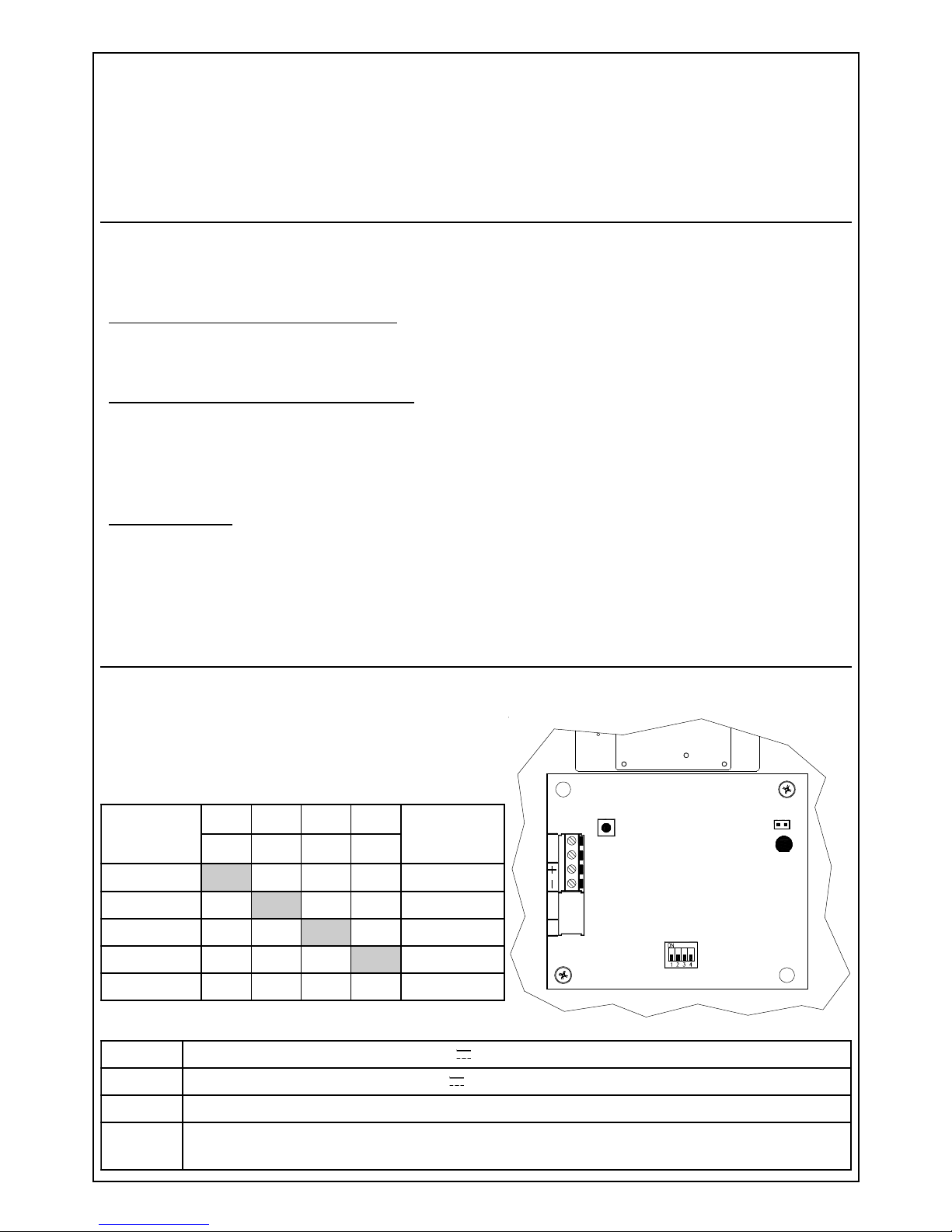
Chapter 2: Transmitter
The transmitter is made of a planar microwave emitting a narrow and directional higly-stable low
power beam.
A 4-dip-switch for setting working frequency is on board.
Check that the transmitter working frequency set is
the same as in the receiver coupled
-
V21evitagengniylppus
+
V21evitisopgniylppus
TT
gnineporotcetedtsiaganoitcetorproftuptuo.c.n
1S
desolc
nepo
delbanedeLgniylppus
delbasiddeLgniylppus
MMB
SLENNAHC
PID PID PID PID
SULPQMB
SLENNAHC
1 2 3 4
1F
NO FFO FFO FFO
DLOG
2F
FFO
NO FFO FFO
EULB
3F
FFO FFO
NO FFO
REVLIS
4F
FFO FFO FFO
NO
WOLLEY
5F
FFO FFO FFO FFO
-
Page 4
- 4 -
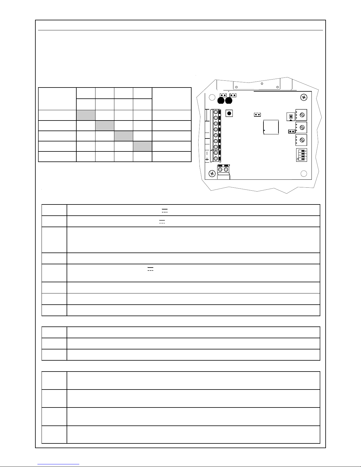
Chapter 3: receiver of hard-wired systems BM60M, BM120M, BM200M
The receiver is made of a high-sensitivity electronic circuit coupled to the antenna; it detects the
signal transmitted in its channel and measures its intensity. Special techniques of signal-elaboration
allow to compensate the variations in the sorroundings and to minimize the effect of possible
perturbations due to small animals or birds.
A 4 dip-switch is on board for setting working frequency
Check that the working frequency of the receiver is
the same as set in the transmitter coupled.
draoBlanimreT
-
V21evitagengniylppus
+
V21evitisopgniylppus
D Am05(evitagendezirotsisnartasevigti;langisnoitacifilauqsiDfotuptuo
rettimsnartehtfolangisehtesacnisliafevitagensihT.noitidnocteiuqgnirud).xam
ces03nihtiwdeviecertonsi
PT
deviecerlangisehtfonoitazilausivroftnioPtseTfotuptuoevitisop
B
mralaeht,lanimretsihtotevitisopagnivig;yb-dnatsrofV21:tupnievitisop
noitidnocteiuqniskcolbyaler
CN/C
yalermralafoegnahcxe..c.n
TT
gnineporotcetedtsniaganoitcetorproftuptuo.c.n
BA
lenapetomerfonoitcennocrofroodlaires
remmirT
LEVEL
deviecerlangisehtgnitsujdarofremmirt
.SNES
esiwkcolcgninrutybsesaercniti;ytivitisnesgnitsujdarofremmirt
.PMOC
esiwkcolc-retnuocgninrutybsesaercniti;noitasnepmocgnitsujdarofremmirt
srepmuJ
1S
desolc
nepo
delbane,evaworcimfoytilauq-langisfodeLneerg
delbasid,evaworcimfoytilauq-langisfodeLneerg
tluafed
2S
desolc
nepo
delbane,gnillangismralafodeLder
delbasid,gnillangismralafodeLder
tluafed
FFO
PMOC
desolc
nepo
dedulcnitiucricnoitasnepmoc
dedulcxetiucricnoitasnepmoc
tluafed
GAC
desolc
desolcniamertsumrepmujsiht
BCA
TPB D
LED
VERDE
TAMPER
T
NC
T
TAMPER
S1 : OFF LED VERDE
LED
ROSSO
S2 : OFF LED ROSSO
CAG
SENS.
OFF COMP.
SW1 COMP.
TEST
CAG
LEVEL
MMB
SLENNAHC
PID PID PID PID
SULPQMB
SLENNAHC
1 2 3 4
1F
NO FFO FFO FFO
DLOG
2F
FFO
NO FFO FFO
EULB
3F
FFO FFO
NO FFO
REVLIS
4F
FFO FFO FFO
NO
WOLLEY
5F
FFO FFO FFO FFO
-
S1: OFF GREEN LED S2: OFF RED LED
GREEN LED
RED LED
Page 5
- 5 -
M_MB
SLENNAHC
PID PID PID PID
SSERDDA
1 2 3 4
1F
NO FFO FFO FFO
1
2F
FFO
NO FFO FFO
2
3F
FFO FFO
NO FFO
3
4F
FFO FFO FFO
NO
4
5F
FFO FFO FFO FFO
5
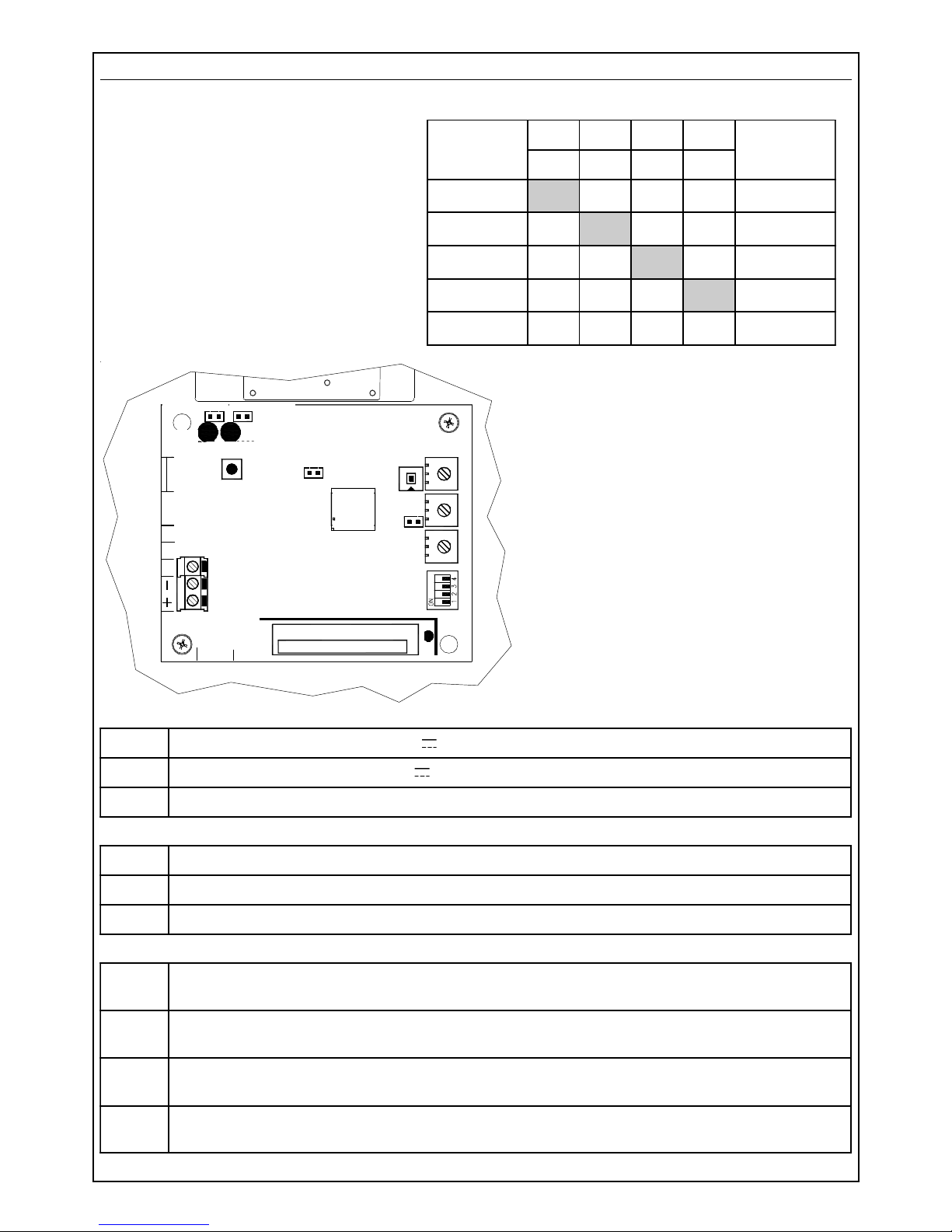
Chapter 4: Receiver of the wireless system BM60M WS
The receiver has the same characteristics as the hard-wired models, with a few differences:
• the 4-ways dip-switch on board
adjusts both working frequency
and the zone address set. If, e.g.,
the beam is addressed on
frequency F2 (dip 1,3,4 in OFF and
dip 2 in ON), it is automatically
acquired as detector 2. It is not
possible to select the working
frequency and the zone address
in the control panel, in a separate way.
•the terminals on board are the supplying
(+ and -) an the signal reading (TP)
•the alarm transmission occurs for both
movement detection inside a pattern and
protracted absence of the signal
received (disqualification): the restore
transmission occurs a few seconds after
the signal is restored in the limits preset.
Check that the working frequency of
the receiver is the same as the
frequency set on the transmitter
coupled.
BCA
TPB D
LED
VERDE
TAMPER
T
NC
T
TAMPER
OFF LED VERDE
LED
ROSSO
OFF LED ROSSO
CAG
SENS.
OFF COMP .
SW1 COMP.
TEST
CAG
LEVEL
LED
TX
S1: OFF LED VERDE
S2: OFF LED ROSSO
S1: OFF GREEN LED S2: OFF RED LED
GREEN LED
RED LED
draoBlanimreT
-
V21evitagengniylppus
+
V21evitisopgniylppus
PT
deviecerlangisehtfonoitazilausivroftnioPtseTfotuptuoevitisop
remmirT
LEVEL
deviecerlangisehtgnitsujdarofremmirt
.SNES
esiwkcolcgninrutybsesaercniti;ytivitisnesgnitsujdarofremmirt
.PMOC
esiwkcolc-retnuocgninrutybsesaercniti;noitasnepmocgnitsujdarofremmirt
srepmuJ
1S
desolc
nepo
delbane,evaworcimfoytilauq-langisfodeLneerg
delbasid,evaworcimfoytilauq-langisfodeLneerg
tluafed
2S
desolc
nepo
delbane,gnillangismralafodeLder
delbasid,gnillangismralafodeLder
tluafed
FFO
PMOC
desolc
nepo
dedulcnitiucricnoitasnepmoc
dedulcxetiucricnoitasnepmoc
tluafed
GAC
desolc
desolcniamertsumrepmujsiht
Page 6
- 6 -
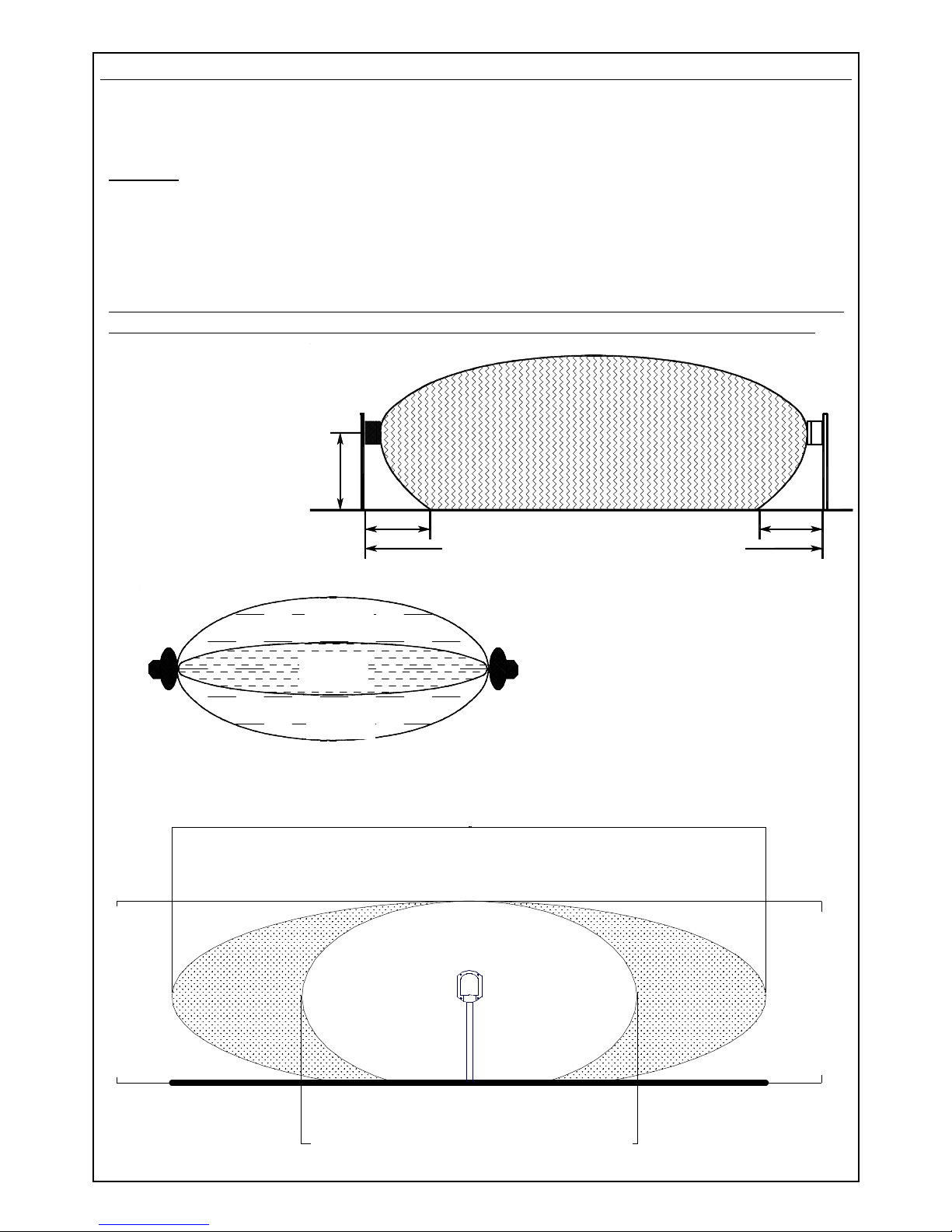
1 - 1,2 mt
BM60M e BM60M WS : max 60 meters
BM120M : max 120 meters
BM200M : max 200 meters
3 meters
3 meters
The sensitive zone shown in the drawings is to
be taken into consideration, as a big target.
Overpassing this area might cause the
same perturbations as a small body
passing the alarm area, that’s to say might
cause false alarms.
BM60M - BM60M WS
6,5 meters
BM120M
10 meters
BM200M
16 meters
BM60M - BM60M WS
2 meters
BM120M - BM200M
3 meters
BM60M - BM60M WS 1,2 meters
BM120M 3 meters
BM200M 4 meters
Alarm zone
Sensitive zone
Sensitive zone
Chapter 5: Description of working
The two units (transmitter: TX and receiver: RX) must be positioned facing each other at the two
ends of the distance to protect. Be aware that the nature of the ground underneath, or special
weather conditions might affect the real range.
Working
The transmitter emits a modulated microwave signal (10,525 GHz), which is received by the
receiver and whose amplitude is compared with the programmed alarm threshold.
When an intruder crosses the microwave area, it causes a signal-intensity decrease under a
minimum level fixed; the receiver shows the alarm condition, lighting up a red Led indicator and
opening the contat of the alarm relay.
If the signal of the transmitter is not received for over 30 seconds, the alarm relay could go back
to quiet condition and the negative to terminal D (disqualification) fails until signal restoring.
For this reason, in the hard-wired system, it is
suggested to make the connection
described in the chapter
concerning disqualification.
The drawings identify the
natural shadow areas
in the immediate
sorroundings of the
two units, which extend
for about 3 meters, in a
typical installation at 1 - 1,2 m
height.
Note: the diagrams of the patterns shown in the drawings are an indication and a guide
during installation. They do not represent the real radiation diagram of the antennas as
they may be subject to variations due to environmental context.
sensitive
zone
sensitive
zone
alarme
zone
Page 7
- 7 -
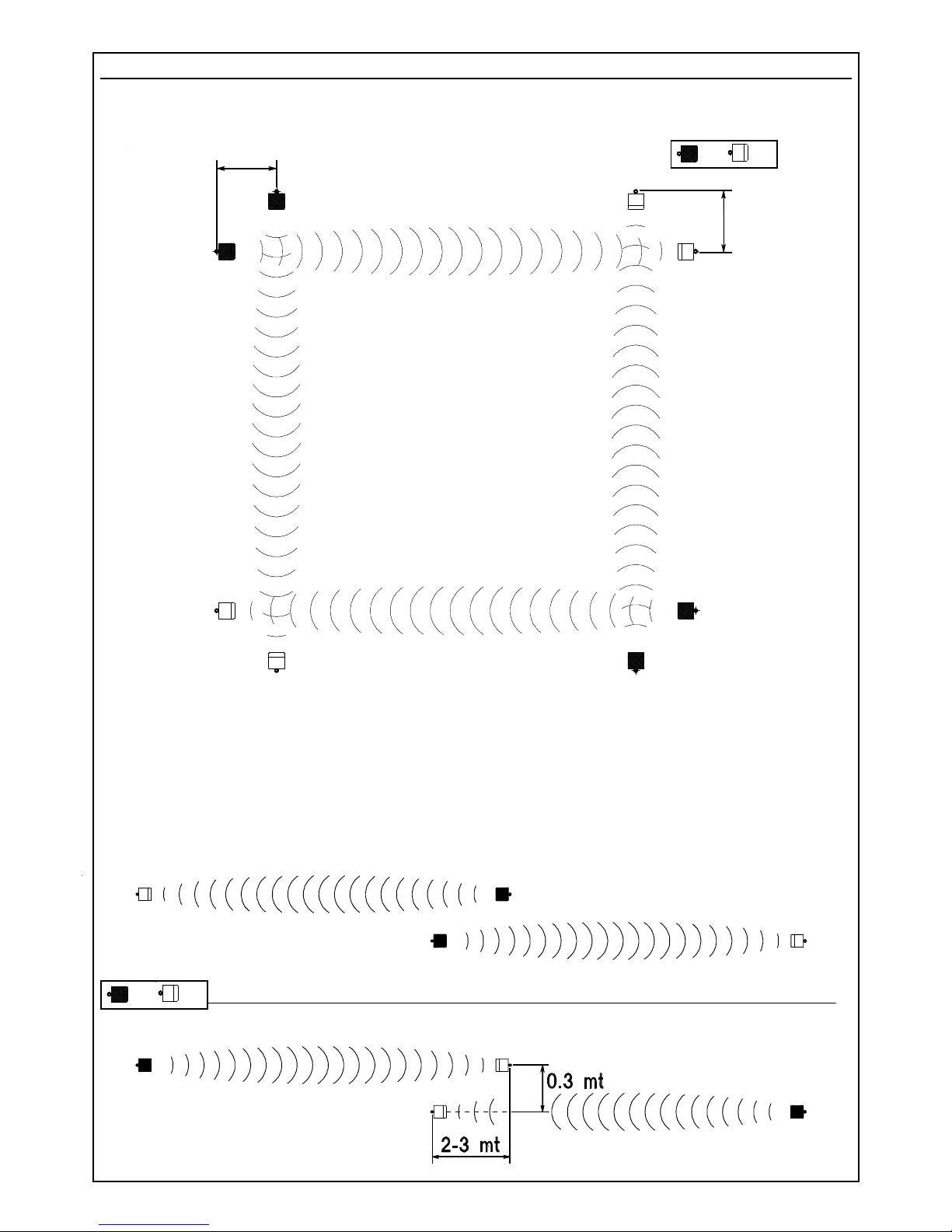
Chapter 6 : Positioning of the beams
For a correct installation of the system, choose carefully the positioning of the two units, according
to following advice:
Drawings identify the correct positioning of transmitters and receivers, in order to eliminate any
possible shadow area.
The drawings here below show how one or more couples of beams have to be positioned for
reaching the distance required.
BE CAREFUL: only elements with different frequencies (F1, F2, F3, F4, F5) and of the
same type (TX/TX or RX/RX) can be installed in proximity one to the other; in order to
avoid interferences between transmitters and receivers belonging to different couples.
The typical installation of
BM M system consists in
sorrounding the area to be
protected by use of more
beams couples in order to
obtain a proper perimetric
fence
3 mt
3 mt
TX RX
TX
RX
Page 8
- 8 -
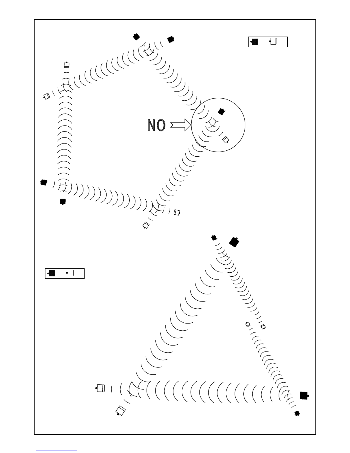
If, in a perimetric installation, the
beams cross the patterns, they
must always be installed in
pair (2, 4, 6 etc.)
It is absolutely
necessary to
avoid installing a
transmitter near a
receiver belonging
to another couple
TX
RX
TX RX
Page 9

- 9 -
In order to extend the height of the protection, two couples of beams
can be installed as shown in the picture. In this case, it is
suggested to use couples of beams having
close working frequency (two couples
with frequency F1 and F2 or F3 and
F4)
BM60M : 1 meter
BM60M WS : 1 meter
BM120M : 10 meters
BM200M : 10 meters
If the fence is made of bushes or metal fences
subject to possible movement, the minimum
distance must be 1 meter for BM60M
and BM60M WS and 10 meters
for BM120M and
BM200M.
Page 10

- 10 -
BM60M : 1 meter
BM60M WS : 1 meter
BM120M : 5 meters
BM200M : 5 meters
If a couple must be installed
near a building or a fix fence, a
minimum distance of 1 meter for
BM60M and BM60M WS and 5 meters for
BM120M and BM200M must be kept.
This is required in order to avoid false alarms
caused by reflection of microwave
beam.
BM60M : 0,6 meters
BM60M WS : 0,6 meters
BM120M : 2 meters
BM200M : 2 meters
A corridor large not less than 0,6 meters for BM60M and
BM60M WS and not less than 2 meters for BM120M
and BM200M, must be left free from obstacles
between transmitter and receiver; a clear
visual must always be granted in this
area
The suggested height for the installation is
between 1 and 1,2 meters.
Page 11

- 11 -
It is possible to install the system BM60M and BM60M WS
also to protect walls. In this case, the system of
installation shown in the drawing can be used,
in order to avoid false alarms caused by
cats or birds. In this case also, the
height from ground must be
between 1 and 1,2 meters.
Because of ground
characteristics, it may
happen to have a very high
sensitivity in the centre of the
protected area and near the ground,
because of special reflection of the ray.
BM60M : 4 meters
BM60M WS : 4 meters
BM120M : 10 meters
BM200M : 10 meters
It is also possible
to install the system
BM M along a transited
street with transit; in this case,
it is necessary to keep a minimum
distance of 4 meters (for BM60M
and BM60M WS) or 10 meters (for
BM120M and BM200M) between the
sight-line of the couple and the area of transit
of the cars.
In case a metal fence is placed between the transit
area and the area to be protected, detectors must be kept
at a minimum distance of 1 meter (for BM60M and BM60M
WS) or 5 meters (or BM120M and BM200M) from the fence.
BM60M : 1 meter
BM60M WS : 1 meter
BM120M : 5 meters
BM200 : 5 meters
Page 12

- 12 -
• Should any pet be present and free in the installation area, it is suggested to carefully adjust
sensitivity, in order to avoid the risk of false alarms due to the passage of these small targets
in the areas which are very sensitive at the ground. To further decrease this risk, the height
of installation of the couple can be increased a little bit.
• Should trees or bushes affect the protection corridor because of the wind, false alarms
might occur. In the same way, if the system is installed near a hedge, this one must be
carefully attended to avoid darkening the protected area.
• High grass ad bushes decrease sensitivity at groud level.
• Any obstacle or important difference of level in the ground in the protected area, create
shadow-areas and very sensitive zones.
The BM M system has a good tolerance against bad weather conditions and temperature
variations; nevertheless it is necessary to care for following situations:
• RAIN: strong rain only causes a decrease of signal power whilst water puddles may increase
sensitivity at ground level
• SNOW: snow fall does not affect beams sensitivity, but the system cannot work if it is entirely
covered by the snow; so take care in areas with frequent and abundant snow
• FOG: a very thick fog can decrease the signal for 1/3. Because of the limits of compensation
of the gain automatic control (C.A.G.) , it is suggested to install the beams couple at a
distance not exceeding 85% of max range,in the regions where a thick fog is frequent.
The temperature working concditions are between - 20°C and + 55°C; if the use is required in
areas where temperature goes lower than 0°C, it is necessary the permanent installation of the
heating kit, which requires an alternate current at 12 V for a consumption of 150 mA for any
element of the beam (see chapter 15 for installation of heating kit).
Page 13

- 13 -
Chapter 7: Advice for installation
• Use special care for the
cables entry, in order to avoid
moisture and rain penetrating
inside the box.
• For cable entry inside the
covers of board protection, use the
cable-loops given within (as shown in the
drawing)
• In the hard-wired system use anti-fire shielded cable (2 x 0,75 mm² + 8 x 0,22 mm²)
In the wireless system, connect the support pole to ground and use an additional
shield for the supplying cable 220 V ~ inside the pole, in order to create a double
isolation.
• Before installing the support poles in a definitve way, it is suggested to make a trail installation
in order to find out the best position of alignement for the best effective detection:
1 Position the beams couple in the centre of a free area, respecting the minimum distances
for beams positioning and the installation height
2 Supply the transmitter and the receiver with two batteries and orientate TX and RX one
towards the other
3 Check the signal on TP and adjust it at 7,3 V .
4 Move the two beams towards RIGHT/LEFT within 30 - 50 cm and Up/Downwards
checking the variations of signal of TP and identifying the signal max point.
5 Once identified the best position, fix the brackets.
• During positioning and adjusting of the Receiver, take care not to have big bodies inside the
sensitive zone, which will then be moved when the system is in use, such as lorries or cars;
the adjustment could be highly affected.
The fixing bracket
is pre-arranged
for the
installation
on a steel
pipe, whose
external
diameter is
40 millimeters
Thanks to the two slides on the sides of
the fixing bracket, it is possible to adjust
the inclination (max 5° upwards
and 5° downwards) in both
transmitter and
receiver.
Two
notches on
the slides indicate the
max inclination
Page 14

- 14 -
Chapter 8: Installation of the transmitter in the hard-wired system
1) Choose the position of the transmitter, fix it at the height desired and orientate it as much
precisely as you can towards the direction where the receiver will be installed
2) Position the 4 dip-switches according to the working frequency chosen
3) Connect the supplying (from 11,5 V to 15 V ) and check the transmitter working by the
lighting-up of the Red Led inside; taking off the jumper S1 (Off Led), it is possible to
disable the Led for reducing consumption
4) Connect the TT terminals of tamper board to tamper line of control panel.
Chapter 9: Installation of receiver in the hard-wired system
1) Install the receiver in the support at the same height of the transmitter
2) Position the 4 dip-switches according to the working frequency chosen
3) Connect the supplying (from 11,5 V to 15 V ) to the positive + and negative - terminals
4) Connect the C and NC alarm outputs and the disqualification output D to the detection
line of the control panel and the TT terminals to anti-tamper line of the control panel
General Warning for the hard-wired system
It is suggested to reach the two units by use of a plastic flexible and waterproof pipe and
to make the connections by use of shielded cables.
The choice of the section of the wires to be used for connections must be made according
to the distance from supplying source, in order to grant a minimum continuous tension of
12 V on both units. Should the supplying tension get lower than this value, bad-functioning
might occur.
Chapter 10: Installation of transmitter in the wireless system
1) Choose the position of the transmitter, fix it at the height desired and orientate it at sight as
much precisely as you can towards the direction where the receiver will be installed.
2) Position the 4 dip-switches according to the working frequency chosen
3) Connect the 230 V ~ supplying to the input of the supply unit given within
4) Connect the support pole to the ground
5) Connect the terminals + and - to the output of the 13,8 V /300 mA supply unit, given within
and check the functioning of the transmitter by the inside red Led (taking off jumper S1 Off
Led it is possible to disable the Led to decrease consumption)
6) Connect the batteries poles to terminals + and - of the supply unit given within
7) In order to have an alarm indication in case of opening of the cover, it is suggested to
connect the TT terminals in series to supplying positive
Chapter 11: Installation of the receiver in the wireless system
1) Install the receiver in the proper support, at the same height of the transmiter
2) Position the 4 dip-switches according to the working frequency chosen
3) Connect the 230V ~ supplying to the input of the supply unit given within
4) Connect the support pole to the ground
5) Connect the terminals + and - to the output of the 13,8 V /300 mA supply unit given within
6) Connect the back-up battery poles to terminals + and - of the supply unit given within
General Warning for wireless system
Create a double isolation for the passing of the mains cable at 220 V ~, inside a
pole, by using an additional shield.
Page 15

- 15 -
LED
VERDE
OFF LED VERDE
PTP1
LED
ROSSO
Chapter 12: Adjustments
1) Orientate at sight the device in the direction of the transmitter and connect a voltmeter
betwen the negative (-) and TP
terminal (Test Point) on board
2) Orientate the device in horizontal
way, looking for the position
giving the max reading; in case
it is over 7,3 Volt tthe signal level
must be reduced by use of
LEVEL trimmer, in such a way
as to bring the signal to the best
point of working, that’s to say 7,3
Volt
• It is possible to have a high value
also with receiver not aligned to
transmitter; in this case it could be a reflection of the beam transmitted, which must most be
taken into consideration.
• In case the signal does not reach 6,8 V having LEVEL trimmer at max, move the device in
vertical way within a limit of 10-20 cm.
• Shouldn’t it be possible to reach the min. value, it will be necessary to decrease the distance
between receiver and transmitter or look for a better alignement position
3) Check the quality of the signal received, keeping in mind that in absence of seeming
movements inside the protected area:
• Green Led on fix: there is no signal noise
• Green Led quick or slow flashing: the signal noise is low but is
anyway detected by the beam
• Green Led slow flashing (off for about 1 second) , the signal
noise is more important and it is near to the intervention
threshold of the beam
In order to have a more precise indication of noise quantity, it is suggested to make
mesurements with an oscilloscope, as specified in chapter 13 (Measurements of the signal
by oscilloscope) on the following page
4) Once reached the best condition of working, make a test through the pushbutton TEST
C.A.G. placed on the receiver board.
Keeping the pushbutton pressed , the red alarm led will light up for about 10 seconds, then
the green led will light up again to show normal working; now the pushbutton can be released
5) At the end of all tests, for a reduced consumption of the receiver, it is possible to take off the
jumpers S1 and S2 (Led OFF) which disable the green led and the red led respectively.
LED
ROSSO
SW1 COMP. SENS. LEVEL
OFF COMP.
TEST
CAG
CAG
TAMPER
LED
VERDE
OFF LED VERDE
OFF LED ROS S O
A
B
TPDB
CNC
TAMPER
T T
LED TX
7,3 Volt
OFF GREEN
LED
GREEN LED RED LED
Page 16

- 16 -
PTP1
PTP2
PTP3
Chapter 13: Measurements of the signal by oscilloscope
In the drawing below, the points where to connect the oscilloscope are shown:
Point B shows the quality of
the signal received
In the graphic here below the wave shapes concerning the signal quality are shown:
1- the beam is in quiet condition and there is no passage of people or any perturbation due to
moving objects, the level is fix . Check that the quiet condition is as described.
2- the beam is disturbed or we are crossing a sensitive area (partial darkening)
3- the beam has been darkened and there is an alarm situation
Point C shows the alarm
threshold (trimmer sens.).
In this case the sensitivity
is adjusted at the half
Point A
(PTP1)
it shows the amplitude
of the signal received
Point C
(PTP3)
it shows the alarm
threshold
Point B
(PTP2)
it shows the quality of
the signal received
C
B
.2 s
0.5 V
.2 s
0.5 V
.2 s
2 .1 V DC
x
10
3 .1 V DC
x
10
0 V
Sensitivity
range
Page 17

- 17 -
Chapter 14: Sensitivity Adjustment
1) Turn trimmer SENS clockwise in the position of minimum sensitivity and make a trial
walking in the central point of the distance covered (point of minimum sensitivity of the
system) and check the behaviour of the green led.
2) If necessary, increase the sensitivity progressively until obtining the answer desired
3) After any sensitivity and orientation adjustment, it is necessary to wait about 20 seconds in
order to have all signals set and make a new trial
Caution: a high sensitivity can cause false alarms in critical conditions (such as strong rain
or snow fall)
4) In the BM M system a special compensation circuit has been included, which can be
adjusted by means of trimmer COMP (turning it clockwise the compensation increases); this
circuit records the perturbations resulting in the microwave area when the target approaches
or moves away crosswise to the pattern and it automatically increases the receiver sensitivity
in order to make easier detection of the target when it crosses the central line of the pattern.
The compensation circuit can be completely excluded taking off the jumper OFF COMP. A
high compensation can cause a false alarm of the beam when there are moving objects
near the pattern.
CAUTION
(BM120M and BM200M ONLY)
Due to larger pattern and to compensation circuit, BM M beams are more sensitive to
perturbations caused by moving objects in the areas near the corridor protected.
Consequently, the security distance to be kept in the installation, especially in respect to
the transit of vehicles, trains, or presence of big trees or bushes, must be increased. In the
special case of a street with vehicles transit, parallel to the protected area, it is suggested
to keep a minimum security distance of 10 meters.
Signal
Signal
Alarm
thresold
ALARM
Extreme Compensation
ALARM
Correct Compensation
Alarm
thresold
Page 18

- 18 -
Chapter 15: Kit TERM (optional) Resistence fo inside heating
• For installation in an indoor or outdoor place
where temperature can go lower than 0°C, it
is necessary to use the heating kit Term
1 in both Receiver ad Transmitter. This has
to be done in order to avoid formation of
condensation which might affect the good
working of the electronic circuit.
• The optional heating kit, is made of a circuit
where an electromechanical thermostat, a
heating resistence and a terminal board
for connection to supplying, are placed.
• Supplying must be given by means of an
external trasnformer with output at alternate 12V ; the consumption of any heating
resistence is 150 mA at the tension of alternate 12 V.
• The thermostate intervention occurs taking
off supplying to the resistence when the temperature of 30° C is reached inside the box.
Chapter 16: Kit AMP (optional) Anti-removal
The anti-removal kit AMP is made of two bulbs, whose
function is sending an alarm in case of tampering or
removal of the beam from its support.
This kit must be positioned in such a way that one of the
bulbs is installed in vertical position compared to the
device and the other one in horizontal position as shown
in the picture.
This system allows a complete protection against any
attempt of :
- removal of the beam from the support
- removal of the supports from fixing points
The horizontal bulb must be positioned in such a way that
the contact opens as soon as there is an attempt of moving
the beam.
Before connecting the tamper line to the control panel,
check that the contact of single bulbs as well as tamper line is closed .
:gniylppuS V21etanretla
:noitpmusnoC xamAm051
:remrofsnarT ~V022:tupni
~V21:tuptuo
rewopW02:smaebfoselpuoc4rof
Example: RX BEAM
CTPB
D
TAMPER
TNCT
Page 19

- 19 -
SUPPLY UNIT
BATTERY
Chapter 17: Disqualification (Important Warning)
In order to prevent and show
disalignements caused by any
obstacle placed in the active
beam of the barriers at system
off, it is necessary to connect
the disqualifiation output
(terminal D) in series to the
exchange of the alarm relay or
alternatively, use it to control an
additional relay, whose
exchange has to be put in series
to the alarm line.
NOTE
The output D gives a
transistorized negative (max. 50
mA) which fails when the signal
level goes under a minimum
level for over 30 seconds.
Chapter 18: Additional supply unit for BM60M WS
In both transmitter and receiver, the supply
unit is fixed inside the cover on the top,
whilst a back-up battery 12V 0,8 Ah is
located in the bottom (to be fixed
with the strip given within), and
not exceeding the following
size: height 65 mm, length 96
mm, depth 25 mm.
Make the supplying
cables pass behind the
supply unit and the
backup battery, in order
not to affect the cover
closing.
Two protection fuses are
available in the supply
unit: F1 for mains
supplying and F2 of
battery input.
F1
F2
-
~ ~
+
+
-
Battery
input
Output
beam
supplying
Mains
supplying
input
1F V052-LAm005
2F V052-LAm005
Balance
Resistence
AVS CONTROL PANEL OTHER CONTROL PANEL
Page 20

- 20 -
A
+
-
B
BR100 is an accessory accepting up to
4 LCD W boards.
Chapter 19: BR100 Kit and LCD W (optional) signal remoting-device
LCD W is a Led and
display module
allowing the
constant
monitoring of
the BM M
signal to
which it is
associated.
This system of remoting the signal levels of the beams, is made of a Led/display module (LCD
W) for any couple of beams, to be contained into the BR100 housing.
Thanks to this system, it is possible to monitor constantly from 1 up to 4 couples of BM M.
On the front of BR100 module, for any couple of beams to monitor, there are:
• the LCD W module for vizualising the signal
quantity received, expressed in Volt (the
display visualizes the units, the Led bar
visualizes the decimals). The value
shown is the same given by the TP
terminal (Test Point) of the receiver to
which it is coupled
• a yellow Led (FAIL) is especially
appointed to the Disqualification
indication
• a red Led (ALARM) indicating the alarm
condition (it follows the condition of the
receiver red Led)
• a green Led (STATUS) visualizing the
signal quality (it follows the condition of the
receiver green Led)
There also is a key-block which must not be
connected (for future uses)
DRAOBLANIMRET
+
V21evitisopgniylppuS
-
evitagengniylppuS
BA
ehtotlaires-eugolaidehtfotupnI
smaebdetaicossa
SCITSIRETCARAHCLACINHCET
noisnetlanimoN V8,31-5,11
noitpmusnoC Am011xam
esuF V052LA5.0F
The supplying of the BR100 panel must be separate from the beams supplying in order to
avoid that a possible short-circuit in the supplying line of the panel can cause the break of
the supplying to the beams. To this purpose, use the fuse-holder with its 500 mA fuse
given within BR100 panel.
Page 21

- 21 -
SB60
GNIKROWNEEWTEBECNEDNOPSERROC
TINUNOITAZILAUSIVDNAYCNEUQERF
MAEB
LENNAHC
PID PID PID PID
TINU
1 2 3 4
1F
NO FFO FFO FFO
1
2F
FFO
NO FFO FFO
2
3F
FFO FFO
NO FFO
3
4F
FFO FFO FFO
NO
4
5F
FFO FFO FFO FFO
1
NOITUAC
1TINUotnosesserddasi5FhtiwtesmaebehT
TEST
CAG
LEVEL
B D TP
PTP2
TT
NC
TAMPER
TAMPER
LED
VERDE
OFF LED VERDE
PTP1
LED
ROSSO
CAG
OFF LED ROSSO
OFF CO M P.
SENS.
LED TX
PTP3
SW1 COMP.
C
B
A
TEST
CAG
LEVEL
B D TP
PTP2
TT
NC
TAMPER
TAMPER
LED
VERDE
OFF LED VERDE
PTP1
LED
ROSSO
CAG
OFF LED ROSSO
OFF CO M P.
SENS.
LED TX
PTP3
SW1 COMP.
C
B
A
TEST
CAG
LEVEL
B D TP
PTP2
TT
NC
TAMPER
TAMPER
LED
VERDE
OFF LED VERDE
PTP1
LED
ROSSO
CAG
OFF LED ROSSO
OFF CO M P.
SENS.
LED TX
PTP3
SW1 COMP.
C
B
A
TEST
CAG
LEVEL
B D TP
PTP2
TT
NC
TAMPER
TAMPER
LED
VERDE
OFF LED VERDE
PTP1
LED
ROSSO
CAG
OFF LED ROSSO
OFF CO M P.
SENS.
LED TX
PTP3
SW1 COMP.
C
B
A
SW1
SW1
SW1
SW1
A
B
RX 1
ABABA
B
RX 2
RX 3
RX 4
+
-
Fuse
Chapter 20: Optional Brackets
SB120
Optional
bracket SB60
can be used
with BM60M
and BM60M WS
only
SB20
The optional
bracket
SB20 and
SB60 can
be used for
installation
to the wall
SB130
Optional brackets SB120 and SB130 can
be used for installation to the floor
Page 22

- 22 -
Information in conformity to the Directive 1999/5/CEE for model BM_M
The product here described is in conformity to the essential prescriptions of the Directive 1999/
5/CEE (R&TTE) on the radio-transmitting devices of low power and on the use of frequencies of
the radioelectrical spectrum, in accordance with CEPT 70-03 recommandation.
kramedarT SCINORTCELESVA
ledoM M002MB-M021MB-M06MB
ycneuqerfgnikroW zhG525,01
gniylppusfoepyT tnerrucsuounitnoc
noisnetlanimoN V21
)XRdnaXT(tnerruclanimoN Am101
ytinummoCnaeporuEehtniesufoseirtnuoC snoitcirtserlacolfonoitpecxeehthtiwreverehW
etaD 6002lirpAht5
DICHIARAZIONE DI CONFORMITA
(MANUFACTURERS DECLARATION OF CONFORMITY)
DICHIARA CHE LA SEGUENTE APPARECCHIATURA
(DECLARES THAT THE FOLLOWING EQUIPMENT)
RISULTA CONFORME CON QUANTO PREVISTO DALLE SEGUENTI DIRETTIVE COMUNITARIE:
(IS IN ACCORDANCE WITH THE FOLLOWING COMMUNITY DIRECTIVES)
E CHE SONO STATE APPLICATE LE SEGUENTI NORMATIVE
(APPLYING THE FOLLOWING NORMS OR STANDARDS)
IDENTIFICATORE DI CLASSE DEL DISPOSITIVO (per apparati RF regolamentati dalla direttiva R&TTE)
(Equipment class identifier (RF products falling under the scope of R&TTE))
Il costruttore dichiara sotto la propria responsabilità che questo prodotto é conforme alla direttiva
93/68/EEC (marcatura) e soddisfa i requisiti essenziali e altre prescrizioni rilevanti della direttiva
1999/5/EC (R&TTE) in base ai risultati dei test condotti usando le normative (non) armonizzate in
accordo con le Direttive sopracitate.
(We declare under our sole responsibility that this product is in conformity with directive 93/68/EEC (Marking)
and/or complies to the essential requirements and all other relevant provisions of the 1999/5/EC (R&TTE)
based on test results using (non)harmonized standards in accordance with the Directives mentioned)
Luogo (Place) : Curtarolo
Data (Date) : April 2006
Firma (Signature)
Nome (Name) : G. BARO
Amministratore
(Managing Director)
erotturtsoC
)rerutcafunaM(
APSSCINORTCELESVA
ozziridnI
)sserddA(
YLATI-)DP(oloratruC01053-36,anaguslaVaiV
:arutaihccerappA’lledemoN
)emaNtnempiuqE(
:
M002MB-M021MB-M06MB
arutaihccerappAidopiT
)tnempiuqEfoepyT(
: ONRETSEREPEDNOORCIMAEREIRRABIROTALEVIR
)METSYSMRALANAPSEVAWORCIMROODTUO(
olledoM
)ledoM(
:
enoizurtsoCidonnA
)erutcafunaMforaeY(
:
6002
)CME(CE/633/98
)ETTR&R(CE/50/99
)DVL(CE/32/37
044003NE
3-984103NE
4-03105NE
05906NE
elbacilppAtoN )tcudorp1ssalc(enoN
X
)tcudorp2ssalc(
Page 23

- 23 -
Information in conformity to the Directive 1999/5/CEE for model BM60M WS
The product here described is in conformity to the essential prescriptions of the Directive 1999/
5/CEE (R&TTE) on the radio-transmitting devices of low power and on the use of frequencies of
the radioelectrical spectrum, in accordance with CEPT 70-03 recommandation.
DICHIARAZIONE DI CONFORMITA
(MANUFACTURERS DECLARATION OF CONFORMITY)
DICHIARA CHE LA SEGUENTE APPARECCHIATURA
(DECLARES THAT THE FOLLOWING EQUIPMENT)
RISULTA CONFORME CON QUANTO PREVISTO DALLE SEGUENTI DIRETTIVE COMUNITARIE:
(IS IN ACCORDANCE WITH THE FOLLOWING COMMUNITY DIRECTIVES)
E CHE SONO STATE APPLICATE LE SEGUENTI NORMATIVE
(APPLYING THE FOLLOWING NORMS OR STANDARDS)
IDENTIFICATORE DI CLASSE DEL DISPOSITIVO (per apparati RF regolamentati dalla direttiva R&TTE)
(Equipment class identifier (RF products falling under the scope of R&TTE))
Il costruttore dichiara sotto la propria responsabilità che questo prodotto é conforme alla direttiva
93/68/EEC (marcatura) e soddisfa i requisiti essenziali e altre prescrizioni rilevanti della direttiva
1999/5/EC (R&TTE) in base ai risultati dei test condotti usando le normative (non) armonizzate in
accordo con le Direttive sopracitate.
(We declare under our sole responsibility that this product is in conformity with directive 93/68/EEC (Marking)
and/or complies to the essential requirements and all other relevant provisions of the 1999/5/EC (R&TTE)
based on test results using (non)harmonized standards in accordance with the Directives mentioned)
Luogo (Place) : Curtarolo
Data (Date) : April 2006
Firma (Signature)
Nome (Name) : G. BARO
Amministratore
(Managing Director)
erotturtsoC
)rerutcafunaM(
APSSCINORTCELESVA
ozziridnI
)sserddA(
YLATI-)DP(oloratruC01053-36,anaguslaVaiV
:arutaihccerappA’lledemoN
)emaNtnempiuqE(
:
SWM06MB
arutaihccerappAidopiT
)tnempiuqEfoepyT(
: ONRETSEREPEDNOORCIMAAREIRRABEROTALEVIR
)METSYSMRALANAPSEVAWORCIMROODTUO(
olledoM
)ledoM(
:
enoizurtsoCidonnA
)erutcafunaMforaeY(
:
6002
)CME(CE/633/98
)ETTR&R(CE/50/99
)DVL(CE/32/37
044003NE
3-022003NE
3-984103NE
4-03105NE
05906NE
elbacilppAtoN )tcudorp1ssalc(enoN
X
)tcudorp2ssalc(
kramedarT SCINORTCELESVA
ledoM SWM06MB
ycneuqerfgnikroW )ycneuqerfgnikrowevaworciM(zhG525,01
)ycneuqerfnoissimsnarT(zHM053,868
gniylppusfoepyT yrettabpu-kcabV21+tnerrucetanretla
noisnetlanimoN Am003~V032
)XRdnaXT(tnerruclanimoN noitidnocteiuqniAm101
noissimsnartgnirudAm131
ytinummoCnaeporuEehtniesufoseirtnuoC snoitcirtserlacolfonoitpecxeehthtiwreverehW
etaD 6002lirpAht5
Page 24

- 24 -
Technical
Characteristics
AVS ELECTRONICS S.p.A.
Via Valsugana, 63
35010 (Padova) ITALY
Tel. 049 9698 411 / Fax. 049 9698 407
avs@avselectronics.com
www.avselectronics.com
Assistenza Tecnica: 049 9698 444
support@avselectronics.com
AVS ELECTRONICS S.p.A. reserves the right to modify the technical and esthetical characteristic of the products at any time.
M06MB M021MB M002MB SWM06MB
egnarxaM sretem06 sretem021 sretem002 sretem06
noisnetlanimoN V21 V21 V21 V21
noisnetniM V5.11 V5.11 V5.11 V5.11
noisnetxaM V51 V51 V51 V51
nihtiwnevigtinu-ylppuS
- - -
~V032:.snettupnI
Am003:tnerruC
AV6:rewoP
V8.31:.snettuO
etacolotyrettaB
- - -
hA8,0-V21
21-8,0PN.doM
teiuqgnirudnoitpmusnoC Am13:XT
Am07:XR
Am13:XT
Am07:XR
Am13:XT
Am07:XR
Am13:XT
Am07:XR
mralagnirudnoitpmusnoC Am13:XT
Am07:XR
Am13:XT
Am07:XR
Am13:XT
Am07:XR
Am13:XT
Am001:XR
)HxLxP(:eziS 591x501x051 522x522x631 522x522x631 522x522x631
ycneuqerfnoissimsnarT - zHM868MF
noitacidnilavivruS on sey
yalerrotcetedfokcolB Blanimretdetnioppayb -
tuptuomralA V21taegnarAm005htiwegnahcxe.c.n -
tuptuorepmaT hctiws-orcim -
)PMA(lavomer-itnaroftiklanoitpO on sey sey on
lairesroftuptuO lenapetomerfonoitcennocrofroodlaires -
QMIenoizatserP QMIolleviLII
tiKnocM002MBeM021MBrepQMIolleviLIII
enoizomiritnA
-
tuptuonoitacifilauqsiD noitpecerdooglangisfognikcehcroftuptuodezirotsisnart
tuptuotnioPtseT deviecerlangisfognikcehcrof
ycneuqerfgnikrowevaworiM )zHM02-/+(zHG525,01
noitaludoM hctiws-pidhguorhtnoitceles,slennahctnereffid5ni
rewopFRfonoitaidarrI mBd52:kaep
snoitidnocerutarepmeT C°55+otC°02-morf
.detseggussi)2mreT(tikgnitaehlanoitpoehtfoesueht,roodtuonoitallatsniroF
noitcetorPPI 43PI
nihtiwneviG ebutmm04nonoitaxifroftekcarB
 Loading...