

Page 1
AA
A
AA
BF100 ABF100 A
BF100 A
BF100 ABF100 A
VS ELECTRVS ELECTR
VS ELECTR
VS ELECTRVS ELECTR
CurCur
tartar
Cur
CurCur
wwwwww
www
wwwwww
olo (Polo (P
tar
olo (P
tartar
olo (Polo (P
.a.a
vselectrvselectr
.a
vselectr
.a.a
vselectrvselectr
adoado
ado
adoado
onicsonics
onics
onicsonics
vv
a) Itala) Ital
v
a) Ital
vv
a) Itala) Ital
ONICSONICS
ONICS
ONICSONICS
yy
y
yy
.com.com
.com
.com.com
SmokSmok
Smok
SmokSmok
detectiondetection
detection
detectiondetection
beambeam
beam
beambeam
ee
e
ee
In conformity to EN54 norms
CERTIFIED
QUALITY SYSTEM
ISO9001
IST0649V1/0
- 1 -
IST0649V1/0
Page 2

GENERAL FEATURES
6
ALLARME
S7
NO
NC
LD3
LD4
LD2
S3S2
321
ON
3
2
1
4
5
B
S8
NO
GUASTO
+F
CNCC
OUT
+
- A
S4
S9
S6
S5
4
8
7
S2
321
ON
+
-
S6
S5
4
-
+
LED
ROSSO
RX
TX
- Smoke detection beam made of a Transmitter and a Receiver, capable to detect and
determine the quantity of smoke which is present in the protected area.
- The board is equipped with a view-finder, placed on one side, allowing a rough alignement
with the reflector given within.
- The beam is equipped with a device (Led/display module) to use for calibration and check of
signal received.
- At first supplying, the board makes a self-calibration which will be repeated every 2 hours in
order to compensate masking caused by dust on lenses and reflector.
- Adjustable sensitivity to get a better intervention threshold according to distance.
- The beam has alarm outputs as well as fault condition and consumption-alarm outputs,
which allow connection to standard fire control units.
- The beam has a serial interface in order to connect up to 4 units to the remote panel (BR100)
showing the same indications as shown by led/display module and leds.
- 2 -
IST0649V1/0
Page 3
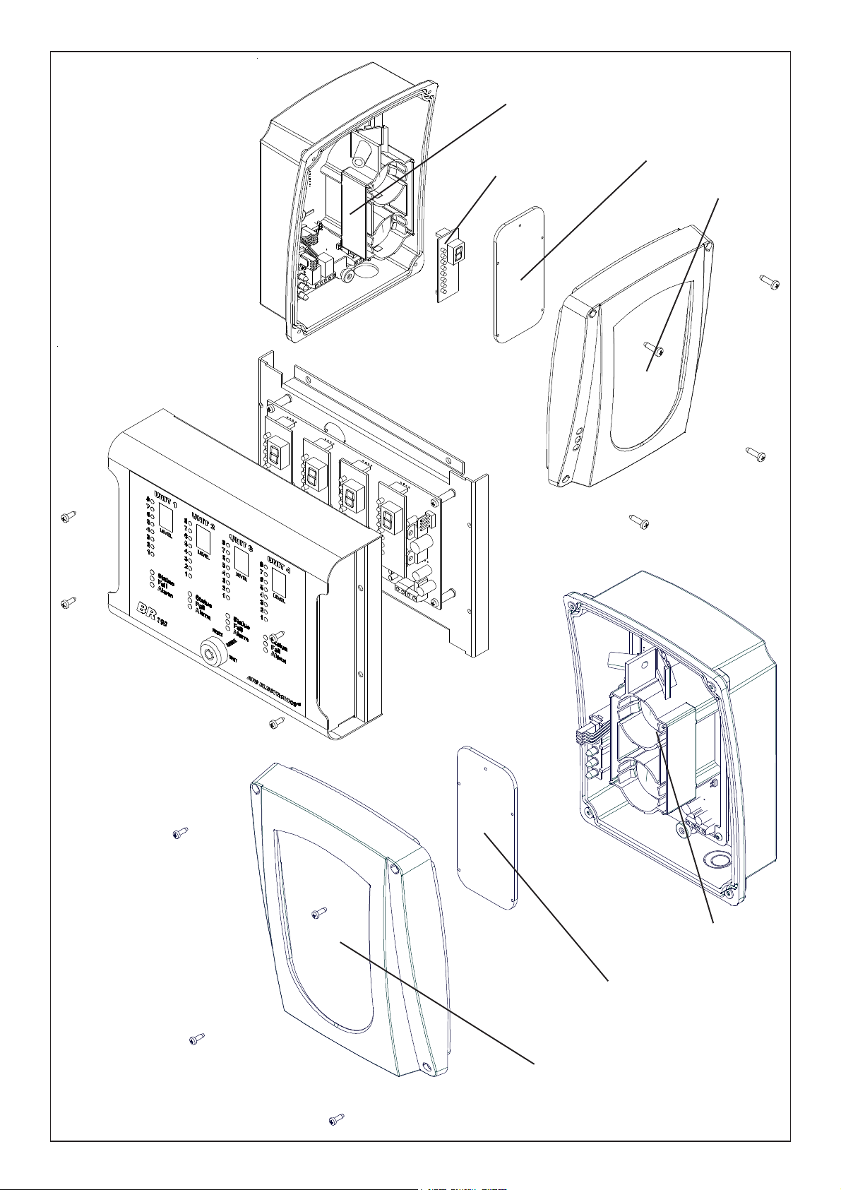
RECEIVER
LED/DISPLAY
MODULE
BF TEST
(NOT GIVEN WITHIN)
COVER
BR100 (OPTIONAL)
TRASMITTER
BF TEST
(NOT GIVEN WITHIN)
COVER
- 3 -
IST0649V1/0
Page 4
RECEIVER
A- B
C
GUASTOALLARME
S7
NC
C
NO
NC
NO
S8
OUT
+F
+
S6
ON/CN
MRALA
.yalerMRALAfoegnahcxE
.detcetedneebsahekomsretfasdnoces04tuobaevitcasitI
.ON/CroCN/Cegnahcxeehttesotredroni7SrepmujnotcA
ON/CN
TLUAF
-OITIDNOC
N
.yalerTLUAFfoegnahcxE
neddusadetcetedsahmaebehtretfaetunim1tuobaevitcas'tI
.levelmuminimehtrednulangisehtfoesaerced
.ON/CroCN/Cegnahcxeehttesot8SrepmujnotcA
C
F+TUO
fonoitcennoctceridehtswollatuptuosihT.yalermralaehtsasetavitcatI
ehtmralagniruD.tinulortnoceriflanoitnevnocfoenilenootmaebeht
.mho086siegrahcecnetsiser
+ )V8,72xam/V5,11.nim(V42roV21evitisopgniylppuS
- evitagengniylppuS
A
001RBeludomlanoitpootnoitcennocrofroodlaireS
B
EDOMNOITARBILAC
DER
2DL
FFO
NEERG
3DL
detcetedtonsirettimsnarTehtfolangisehtfi:FFO
detcetedsilangisrevieceRehtfi:NO
WOLLEY
4DL
FFO
EDOMLAMRON
DER
2DL
FFO
NO
noitidnoclamroN
mralA
NEERG
3DL
gnihsalfwolS
gnihsalfkciuQ
)sdnoces2yreve(noitidnoclamroN
dlohserhtmralaehtgnideecxeekomshtiW
WOLLEY
4DL
FFO
gnihsalfkciuQ
NO
noitidnoclamroN
mrala-erpnoitidnoctluaf(muminimrednulevellangiS )
noitavitcayalertluaffoemitemasehttA
S7 S8
1 2 3 4
S2 S3 S4
ON
S1
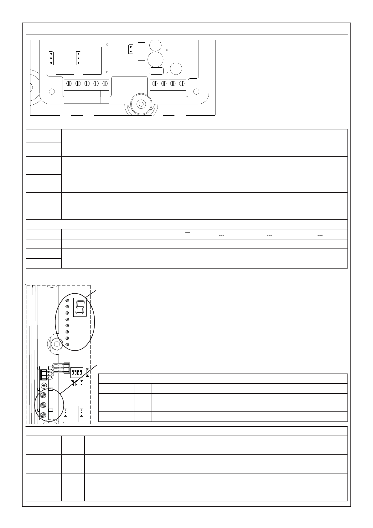
The terminal board is made of
two separate groups: the one
on the left concerns alarm
and fault-condition output
whilst the one on the right
concerns supplying input and
serial door.
Signalling Led
8
7
6
5
4
3
2
1
LD2
LD3
LD4
Module to visualize the signal:
– during normal working, the display will visualize the unit values while
the Led bar will visualize the decimanl values of the signal received.
– during alarm condition the letter A is visualized.
– during fault condition the letter F is visualized.
- during calibration the display visualizes the unit values whilst the Leds
bar visualizes the decimal values of signal received.
Module for visualization of detector condition:
IST0649V1/0
- 4 -
Page 5
Jumper
1S
)repmuj-eriW(
ylnoesuyrotcaf,tuctonoD
2S 001RBeludometomerhtiweugolaidrofnoitcelessserddA
3S 001RBeludometomerhtiweugolaidrofnoitcelessserddA
4S 001RBeludometomerhtiweugolaidrofnoitcelessserddA
5S
rotaunettA
)repmuj-eriW(
desolC
nepO
rotcelferdnamaebneewteb.tm001ot53morfecnatsidroF
rotcelferdnamaebneewteb.tm53ot5morfecnatsidroF
6S
gniylppuS
)repmuj-eriW(
desolC
nepO
gniylppusV21
gniylppusV42
7S
yalerMRALA
tcatnocCN:2-1noitisopnI
tcatnocON:3-2noitisopnI
8S
yalerTLUAF
tcatnocCN:2-1noitisopnI
tcatnocON:3-2noitisopnI
9S
MRALA
TESER
desolC
nepO
lortnoceriflanoitnevnocafoenilehtotdetcennocF+tuptuofiylnO
gnillangismralarofdesusitinu
sedomnoitcennocrehtollanI
1
levelytivitisnesfognitteS
2 levelytivitisnesfognitteS
3
FFO
NO
gnikrowlamronfoedoM
gnikrownoitarbilacfoedoM
4 desutoN
S7 S8
S2 S3S9S4
S6
S5
ON
1 2 3S14
Dip switch
ON
1 2 3 4
S1
- 5 -
IST0649V1/0
Page 6

TRANSMITTER
2S
desolC
nepO
)ffodeLdeR(noitarbilaC
)nodeLdeR(gnikrowlamroN
5S
ecnatsiD
noitceleS
)repmuJ(
desolC
nepO
53neewtebdedulcnireviecerdnarettimsnartneewtebecnatsidroF
.sretem001dna
5neewtebdedulcnireviecerdnarettimsnartneewtebecnatsidroF
sretem53dna
6S
gniylppuS
desolC
nepO
gniylppuSV21
gniylppuSV42
+
-
1PID 2PID 3PID 4PID
EGNAR
)5Snepohtiw(
EGNAR
)5Sdesolchtiw(
0 0 0 0 5 tm83
1 0 0 0 51 tm55
0 1 0 0 02 tm86
1 1 0 0 32 tm87
0
0 1 0 72 tm78
1 0 1 0 03 tm69
0 1 1 0 33 tm501
1 1 1 0 73 tm311
-
+
S2
321
ON
S6
S5
4
LED
ROSSO
+ )V8,72xam/V5,11.nim(V42roV21evitisoPgniylppuS
- evitageNgniylppuS
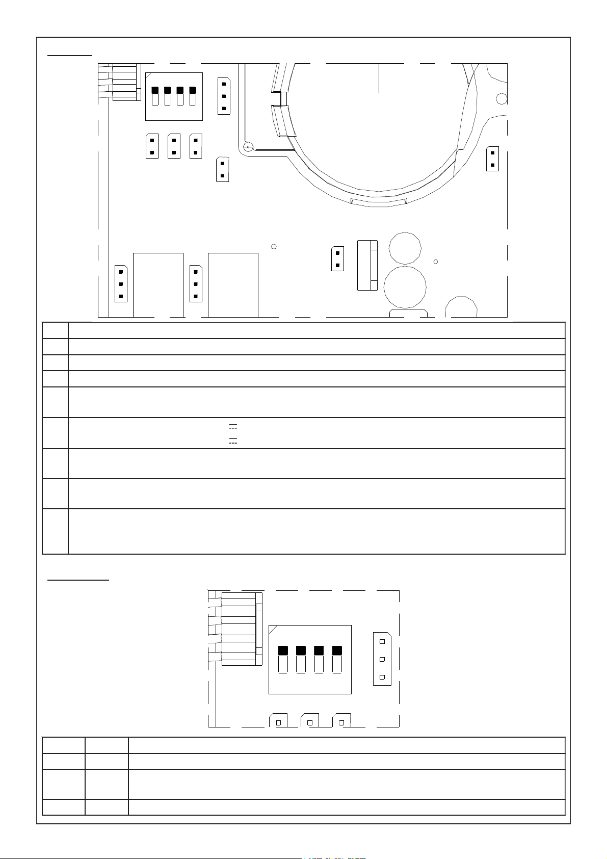
Terminal board
Jumper e Dip Switch
It shows the presence of the supplyng
RED
LED
Trimmer
RV1
- 6 -
For a correct
adjustment of the
beam signal it is also
necessary to set the
distance between
receiver and
transmitter by use of
dip-switch.
Trimmer RV1 for trimming the
emitted signal.
It increases clockwise.
IST0649V1/0
Page 7

INSTALLATION RULES
The beam and the reflector must be installed on plane wall, not subject to vibrations or deformation.
Please keep in mind these basic rules:
- In order to obtain total coverage,
the distance (D) between more
TX/RX couples must not
exceed 15 meters.
- distance from the walls
must be about the half
of the distance between
two beams (1/2 D).
- distance from the ceiling (H)
must be between min. 40 cm.
and max 1 meter.
- check the possibility of installing
reflectors in axis with beams.
H
1/2 D
TX/RX TX/RX
D
1 mt
D
TX/RX
In case of sloping roofs, install the first beam at H
distance from the highest side of the roof.
Install other beams maintaining distance D
between them and distance H from the ceiling.
Check to have the max distance of 1/2D
between the beam and the wall from the
lowest side of the roof.
Check that Receiver and
Transmitters can be installed on
the same axis.
In case of inclination of the roof, install the first beam at about 1
meter from the highest wall and at H distance from the
ceiling.
D
TX/RX
TX/RX
TX/RX TX/RX
Install other beams maintaining distance D
1/2 D
between them and distance H from the
ceiling.
Check to have max 1/2 D
distance between the beam
and the lowest side of the
wall from the ceiling.
Check that Receiver and
Transmitters can be
installed on the same axis.
H
TX/RX
1/2 D 1/2 DD D
- 7 -
IST0649V1/0
Page 8

INSTALLATION
For installation onto the wall either reflector and beam need flat cylindrical-head
screws.
Install the Receiver in the chosen point and keep it in axis
to the Transmitter as much as possible
Alignment hole
Fixing holes
Insert the calibration accessory BF TEST
(necessary for a correct calibration) in the proper
openings, as shown on the drawing on the side,
keeping the alignment hole on the top.
MIN 5 MT
MAX 100 MT
Check not to have reflecting bodies, such as glasses, mirrors etc. possibly affecting
the signal, in the area nearby.
Install the Transmitter in the chosen point and keep it in axis to
the Receiver as much as possible
Alignment hole
Fixing holes
Insert the calibration accessory BF
TEST (necessary for a correct calibration)
in the proper openings, as shown on the
drawing on the side, keeping the alignment hole
on the top.
- 8 -
IST0649V1/0
Page 9

WORKING MODE “CALIBRATION”
leveL foegatnecreP
gniksam
dnamaebneewtebecnatsiD
rotcelfer
1PID 2PID
1 %02 sretem53ot5morF NO NO
2
%52 sretem05ot01morF FFO NO
3 %03
sretem07ot02morF NO FFO
4
%53 sretem001ot03morF FFO FFO
- In order to make a first rough alignement, use optical
view-finder, visualizing the centre of the concerned
reflector in the centre of the framed area. In order to
move orientation towards right, rotate the horizontal
adjuster clockwise, in order to move orientation
towards left, rotate the horizontal adjuster
counter-clockwise.
- To move orientation upwards rotate the
vertical adjuster counter-clockwise, to move
it downwards rotate the adjuster
clockwise.
- Make the same with the Transmitter
- Before supplying the beam check
jumper S6 condition:
• keep it closed for 12V supplying
• cut it for 24 V supplying
DX
UP
SX
REFLECTOR
- Before supplying the beam units, check S6
jumper in both Receiver and Transmitter:
• cut jumper for distance from 5 to 35 meters.
• keep jumper closed for distance from 35 to 100 meters.
- Set properly dip switch 1 - 2 - 3 in the Transmitter according to the distance from Receiver as
shown in chart on page 6
- At firs supplying, the beam is blocked for about 30 seconds. Wait before following step.
- At power up, the beam units remain inhibited for about 30 seconds. Wait for this delay before
proceeding to following step.
- Close S2 jumper in the Transmitter in order to get the beam units to Calibration mode.
• the green Led in the Receiver will remain on if the signal is received from Transmitter
• the display/Led module will visualize the recived signal
- During calibration process avoid the visualized value exceeding 7,1V (7 display - 1 led).
Should this occur, act on the trimmer RV1 to decrease the signal under the threshold.
- Adjust both Receiver and Transmitter until obtaining the max signal value on the display/Led
module in the Receiver.
- Act on Transmitter RV1 Trimmer until obtaining the value of 6,5 V on the display/led module
(6 display and 5 Leds on) of the Receiver.
VERTICAL
ADJUSTER
HORIZONTAL
ADJUSTER
- Considering that the longer is the range, the longer is the beam, it is necessary to set the
sensitivity level in the Receiver according to the distance between Receiver and Transmitter,
following the rules below:
At the end of calibration, open jumper S2 in the Transmitter and take away the BF Test small
glasses before inserting the covers.
The 4 fixing screws of the covers can be “hidden” by using the screw-covers given within, just for
esthaetical reasons.
- 9 -
IST0649V1/0
Page 10

WORKING MODE “NORMAL”
1
3
2
5
4
7
6
8
1
3
2
5
4
7
6
8
1
3
2
5
4
7
6
8
Here are the indications given by the three Leds on the left:
– during normal working: green Led flashes about every 2 seconds, red Led is off, yellow
Led is off.
– during alarm: as soon as the beam detects presence of smoke, green Led will flash quickly,
red Led and yellow Led will be off. After about 40 seconds if the event causing the alarm
continues, green Led will keep on flashing quickly, red Led will be on and alarm relay will be
activated, yellow Led will be off.
When the event causing the alarm is over, green Led will start again flashing every 2 seconds,
red Led will remain on and alarm relay will remain activated.
The alarm signalling is reset:
– if the output +F connected to a conventional fire control unit (Jumper S9 closed)
has been used for the alarm signalling, the reset will be automatic resetting the
control unit.
– For all other connection modes (Jumper S9 opened), the reset is made taking off
supplying from barrier for few seconds.
– In any case, if the module BR100 is used, reset can also be made by use of the
mechanical key on board.
– In case of fault condition: as soon as the beam detects a sudden drop of signal, green Led
will flash quickly, red Led will be off, yellow Led will flash quickly. After about 1 minute, if the
the event causing it persists, green Led will keep on flashing quickly, yellow Led will be fix on
and concerned relay is activated.
– Fault signalling is automatically reset as soon as the event stops. The beam is automatically
back in condition of “normal working”.
You can use the display/Led module both keeping it in its position inside the Transmitter or
inserting it inside the remote panel BR100. In any case you can have to following additional
indications:
During normal working:
DISPLAY
- it shows the value of 6 corresponding to the signal received
LED BAR
- N° led on: 5 (or value shown during adjustment)
In case of alarm:
DISPLAY
- shows letter “A”
LED BAR
- not relevant (depending on signal received)
In case of faulty unit:
DISPLAY
- shows letter “F”
LED BAR
- not relevant (depending on signal received)
- 10 -
IST0649V1/0
Page 11

LD3
LD4
LD2
4321
ON
S1
S8
+F
OUT
NO
ALLARMENOGUASTO
CNCC
NC
S4S3S6S2
S7
+
- BA
S5
LD3
LD4
LD2
4321
ON
S1
S8
+F
OUT
NO
ALLARMENOGUASTO
CNCC
NC
S4S3S6S2
S7
+
- BA
S5
LD3
LD4
LD2
4321
ON
S1
S8
+F
OUT
NO
ALLARMENOGUASTO
CNCC
NC
S4S3S6S2
S7
+
- BA
S5
LD3
LD4
LD2
4321
ON
S1
S8
+F
OUT
NO
ALLARMENOGUASTO
CNCC
NC
S4S3S6S2
S7
+
- BA
S5
BR100
REIRRAB 1 2 3 4
2S
DESOLC NEPO NEPO NEPO
3S
NEPO DESOLC NEPO NEPO
4S
NEPO NEPO DESOLC NEPO
noisnetlanimoN V8,72-5,11
noitpmusnoC Am011xam
esuF V052LA5.0F
1S
:nepO
:desolC
gniylppusV42
gniylppusV21
In order to obtain signal visualizatioin in real time, it is possible to remote the display/led module
of any single beam, locating it in remote panel BR100.
Any BR100 remote panel can locate
up to 4 display/Led modules.
RESET: it makes a reset of alarm
condition.
NORMAL: during normal working of
beams.
TEST: not used
BR100 Connection
Dialogue between the remote panel and the beam occurs
thanks to a serial connection as shown on side drawing.
Connect A and B terminals of beam to concerned A and
B terminals on BR100 remote panel.
Single beams connected to BR100 must be addressed using
Jumpers S2, S3 and S4 on board (see chapter JUMPER), in
the following way:
BR100 supplying must be separate from beams
supplying as a possible short-circuit in remote panel
supplying may cause a cut in beams supplying
(EN54-12 norm). To this purpose use 500 mA fuse
together with its fuse-holder given within BR100 panel.
- 11 -
Fuse
-
A
B +
-
+
Supplying
TECHNICAL FEATURES
IST0649V1/0
Page 12

ALLARME
NO
NC
+FGUASTO
C
NO
NC
C
OUT
+
- BA
CONNECTIONS TO CONTROL UNITS
ALLARME
NO
NC
+F
GUASTO
C
NO
NC
C
OUT
BF100R beam is equipped with:
- OUT + F for direct connection to
AVS conventional fire control units
(charge of 680 ohm during alarm).
In order to reset the beam from
alarm condition, simply make a
reset operation on control unit
(Jumper S9 closed).
Side-drawing shows an example
of connection using these
contacts: R1 is the end-line
resistance usually given with
control unit. FAULT contact is set
on C/NC.
R1
- Relay ALARM output.
Contacts of this output can be C/NC or C/
NO according to setting of jumper S7 (see
chapter JUMPER).
In order to reset the beam from alarm
condition, it is necessary to take off supplying
from the beam for a few seconds (Jumper
S9 open).
An example of connection using these contacts is
shown on side-drawing where ALARM contact is
set on C/NO and FAULT relay is set on C/NC.
R1 is the end-line resistence which is usually given
within control unit.
R2 is the alarm resistence (for AVS control units
the value of this resistence is 680/1000 ohm –
3W) (not included).
R2
R1
In both cases, if module BR100 is used, reset can be done through mechanical key on board.
- 12 -
IST0649V1/0
Page 13

- 13 -
IST0649V1/0
Page 14

- 14 -
IST0649V1/0
Page 15

Indice
GENERAL FEA TURES.................................................................................................pag. 2
RECEIVER....................................................................................................................pag. 4
Signalling Led.......................................................................................................pag. 4
Jumper ..................................................................................................................pag. 5
Dip switch .............................................................................................................pag. 5
TRANSMITTER ............................................................................................................pag. 6
Terminal board......................................................................................................pag. 6
Jumper e Dip Switch ............................................................................................pag. 6
Trimmer.................................................................................................................pag. 6
INSTALLATION RULES ...............................................................................................p ag. 7
INSTALLATION ............................................................................................................pag. 8
WORKING MODE “CALIBRA TION”............................................................................pag. 9
WORKING MODE “NORMAL” ..................................................................................pag. 10
BR100 Connection ....................................................................................................pag. 11
BR100.........................................................................................................................pag. 11
CONNECTIONS TO CONTROL UNITS .....................................................................pag. 12
TECHNICAL FEATURES...........................................................................................p ag. 16
- 15 -
IST0649V1/0
Page 16

:rotcetedfoepyT rotcetedekomsmaeb-derarfnideslupdnadetaludom
egnaR sretem5.nim
sretem001.xam
egarevoC xamsretem.qs000.1
noitarbilaC rabdeL/yalpsidfoesuyb
tiklanoitpO 001RB rabdel/yalpsidrofgnisuohetomer:
TSETFB noitarbilacrofrorrimllams:
gniylppuS tloV8,72ot5,11morf
noitpmusnoCXT eludomhtiwV21htiw- Am32
eludomhtiwV42htiw- Am6,32
noitpmusnoCXR eludomV21htiwnoitidnocteiuq- Am94
eludomV21htiwnoitidnocmrala- Am96
eludomV42htiwnoitidnocteiuq- Am35
eludomV42htiwnoitidnocmrala- Am87
rabdeL/eludomyalpsid- Am51
:stuptuO yalermrala- V21taAm005
yalertluaf- V21taAm005
stinulortnoceriflanoitnevnocotnoitcennoctcerid-
lenapetomerotnoitcennocrofroodlaires-
:erutarepmeT C°04+/C°5+
:eziS .mm112x951x69
:noitcudorP smron45NEINUotgnidrocca
eergedPI 46PI
TECHNICAL FEATURES
The product is in conformity to CE directives for electro-magnetic compatibility.
Power to this device must come from a SELV type power supply having characteristics of
current limitation and fuse protected output. (ref. EN 60950)
INSTALLATION MUST BE PERFORMED BY QUALIFIED PERSONNEL
AVS ELECTRONICS S.p.A. reserves the right to modify the technical and esthetical characteristic of the products at any time.
VS ELECTRVS ELECTR
AA
VS ELECTR
A
VS ELECTRVS ELECTR
AA
Tel. 049 9698 411 / Fax. 049 9698 407Tel. 049 9698 411 / Fax. 049 9698 407
Tel. 049 9698 411 / Fax. 049 9698 407
Tel. 049 9698 411 / Fax. 049 9698 407Tel. 049 9698 411 / Fax. 049 9698 407
Assistenza Tecnica: 049 9698 444Assistenza Tecnica: 049 9698 444
Assistenza Tecnica: 049 9698 444
Assistenza Tecnica: 049 9698 444Assistenza Tecnica: 049 9698 444
support@avselectronics.comsupport@avselectronics.com
support@avselectronics.com
support@avselectronics.comsupport@avselectronics.com
ONICS SONICS S
ONICS S
ONICS SONICS S
Via Valsugana, 63Via Valsugana, 63
Via Valsugana, 63
Via Valsugana, 63Via Valsugana, 63
35010 (Padova) ITALY35010 (Padova) ITALY
35010 (Padova) ITALY
35010 (Padova) ITALY35010 (Padova) ITALY
avs@avselectronics.comavs@avselectronics.com
avs@avselectronics.com
avs@avselectronics.comavs@avselectronics.com
www.avselectronics.comwww.avselectronics.com
www.avselectronics.com
www.avselectronics.comwww.avselectronics.com
- 16 -
.p.p
.p
.p.p
.A..A.
.A.
.A..A.
IST0649V1/0
 Loading...