

Page 1
DT-AVR
ATMEGA328 CPU Module
DT-AVR ATMEGA328 CPU Module is an
AVR® ATmega328(P) based microcontroller module. It
features an In-System Programming (ISP). This module can
be connect to the DT-COMBO BASE BOARD Series and
used for various applications.
Specif ications
1. ATmega328(P) based (32 KB Flash Memory, 1 KB
EEPROM, & 2 KB Internal SRAM).
2. Up to 22 Input/Output pins, including 2 8bits
timers/counters, 1 16bits timer/counter, 6 PWM
canals, 8 10bits ADC canals, serial USART, watchdog
timer, and analog comparator.
3. 8 MHz crystal oscillator.
4. A port for ISP programming
5. Programming LED indicator.
6. 2.7 – 5.5 Volts DC power supply (VCC).
7. Compatible with the DT-COMBO BASE BOARD Series.
Layout
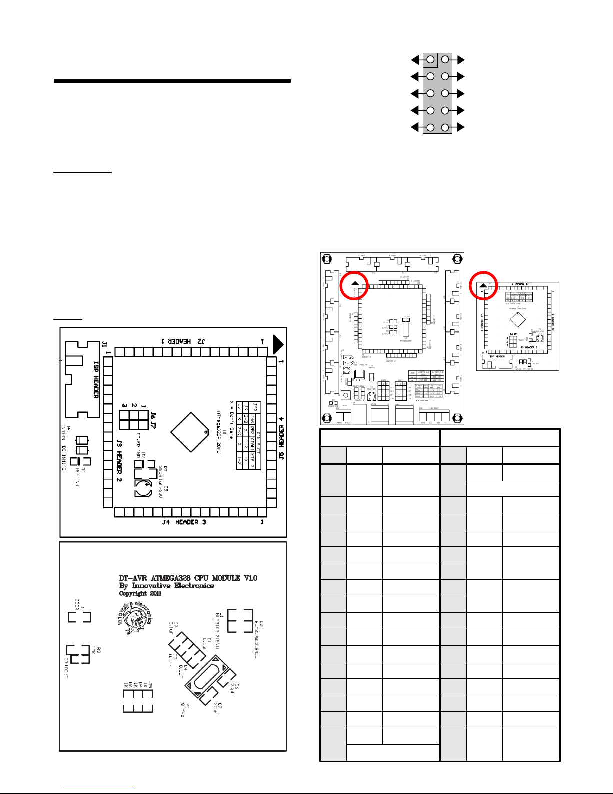
ISP HEADER (J1) is a connector for ISP programming.
HEADER 1 (J2), HEADER 2 (J3), HEADER 3 (J4), and
HEADER 4 (J5) connectors are power supply and
input/output lines that can be connected to SOCKET 1 SOCKET 8 on the DT-COMBO BASE BOARD Series. Use
the triangle marks on both modules as reference. Both
marks should be in the same position and direction. Also
pay attention to the position of the CPU MODULE
connectors so that the installation is precisely aligned
between pins (not shifted).
HEADER 1 HEADER 2
No. Name Function No. Name Function
1 - Not connect 1
PB.7 Port B bit 7
depends on jumper J7
2 PD.0 Port D bit 0 2 - Not connect
3 PD.1 Port D bit 1 3 - Not connect
4 PD.2 Port D bit 2 4 RST Reset
5 PD.3 Port D bit 3 5
VCC
Power
supply input
6 PD.4 Port D bit 4 6
7 PD.5 Port D bit 5 7
PGND Ground
8 PD.6 Port D bit 6 8
9 PD.7 Port D bit 7 9 PC.5 Port C bit 5
10 PB.0 Port B bit 0 10 PC.4 Port C bit 4
11 PB.1 Port B bit 1 11 PD.0 Port D bit 0
12 PB.2 Port B bit 2 12 PD.1 Port D bit 1
13 PB.3 Port B bit 3 13 - Not connect
14 PB.4 Port B bit 4 14 - Not connect
15 PB.5 Port B bit 5 15 - Not connect
16
PB.6 Port B bit 6
16 - Not connect
depends on jumper J6
VCC
GND
GND
GND
GND
MOSI
LED
RESET
SCK
MISO
1 2
Page 2
HEADER 3 HEADER 4
No. Name Function No. Name Function
1 - Not connect 1 AVCC
ADC power
supply input
2 - Not connect 2 AGND Ground
3 - Not connect 3 AREF AREF
4 - Not connect 4 PC.0 Port C bit 0
5 - Not connect 5 PC.1 Port C bit 1
6 - Not connect 6 PC.2 Port C bit 2
7 ADC7 ADC ch. 7 7 PC.3 Port C bit 3
8 ADC6 ADC ch. 6 8 PC.4 Port C bit 4
9 PC.5 Port C bit 5 9 PC.5 Port C bit 5
10 PC.4 Port C bit 4 10 ADC6 ADC ch. 6
11 PC.3 Port C bit 3 11 ADC7 ADC ch. 7
12 PC.2 Port C bit 2 12 PGND Ground
13 PC.1 Port C bit 1 13 VCC
Power
supply input
14 PC.0 Port C bit 0 14 - Not connect
15 - Not connect 15 - Not connect
16 - Not connect 16 - Not connect
Important!
• AVCC and VCC are connected by an inductor.
• PGND and AGND are connected by lines on the
PCB.
• Port D on the IC will appear as PORT E on the DT-
COMBO BASIC BASE BOARD.
• When using Port C as ADC, PORT F on the DT-
COMBO BASIC BASE BOARD can also be used.
• Pay attention PORT C and PORT F pin 9 and 10
are ADC pins and not digital I/O pins on DTCOMBO BASIC BASE BOARD.
• Pay attention to the pin order at the DT-AVR
ATMEGA328 CPU MODULE when connecting it
with another module.
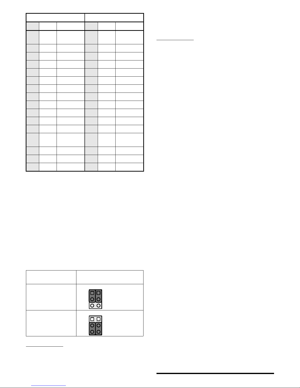
Jumper J6 and J7 are used to select function and line of
PB.6 (J6) and PB.7 (J7).
PB.6 and PB.7
Functions
J6 and J7 Positions
PB.6 and PB.7 on IC
are connected to the
crystal oscillator
(J6 = 1 - 2)
(J7 = 1 - 2)
PB.6 and PB.7 on IC
are connected to
HEADER 1 and HEADER
2
(J6 = 2 - 3)
(J7 = 2 - 3)
CD /DVD Contents
1. CodeVisionAVR© evaluation.
2. Testing program for ATmega328P in CodeVisionAVR
©
C language.
3. Datasheet.
4. DT-AVR ATmega328 CPU Module Manual.
5. DT-AVR ATmega328 CPU Module Schematic.
6. Innovative Electronics Website.
T esting Procedure
1. This test uses the DT-COMBO BASIC BASE BOARD.
Connect DT-AVR ATMEGA328 CPU MODULE to it.
2. On the DT-COMBO BASIC BASE BOARD perform
these following steps:
• Release jumper J31 and arrange jumper J34 and
J35 to point 2-3.
• Arrange jumper J22, J23, J24, J25, J26, J27,
J28, and J29 to point 2-3.
• Connect PORT B, PORT C, AND PORT E with DT-
I/O LED LOGIC TESTER or a series of active low
LED.
• Connect J1 (UART0) or J2 (UART1) DT-COMBO
BASIC BASE BOARD with the computer serial port
using a serial cable.
3. Arrange jumper J6 and J7 to position 1-2 and
connect ISP HEADER on the DT-AVR ATMEGA328
CPU MODULE with DT-HiQ AVR In System
Programmer or other compatible programming tools.
4. Connect a 6,5-12 Volt DC power supply to the DTCOMBO BASIC BASE BOARD DC port. The power LED
on the DT-AVR ATMEGA328 CPU MODULE and DTCOMBO BASIC BASE BOARD will light up. If one or
both LEDs do not light up, recheck the connections
between the modules and the power supply.
5. Program the ATMEGA328 TEST FILE.HEX using DTHiQ AVR In System Programmer or other compatible
programming tools. During the download process, the
programming indicator LED will light up.
6. If the download process succeeded, the LEDs
connected to Port A, Port B, Port C, and Port D (on
Port E) will light up alternately representing the
binary numbers of 0-255. The LEDs at Port D bit 0
and 1 will not light up because they are used as
UART0 serial communication lines. While the LEDs on
Port B and C will only light up from bit 0 to bit 5.
7. Run the terminal program on the computer to see the
serial data sent by the module to the computer. This
serial communication uses the following configuration:
• Baud rate : 9600 bps
• Data bit : 8
• Parity : none
• Stop bit : 1
• Flow control : none
8. When using a HEX view (not ASCII), monitor screen
will show hex numbers from 00H up to FFH sent
repeatedly.
Trademark & Copyright
AVR is registered trademark of Atmel Corporation.
CodeVisionAVR is copyright by Pavel Haiduc, HP InfoTech s.r.l.
♦ Thank you for your confidence in using our products, if there
are difficulties, questions, or suggestions regarding this
product please contact our technical support:
1
2
3
J6 J7
1
2
3
J6 J7
 Loading...