

Page 1
AC-EX40-444-KIT
AC-EX40-444-KIT
Ultra Slim 40m (70m HD) 4K60 4:4:4, HDR
HDBaseT Extender Audio Extraction, EDID
Management, Scaling
3518 N Casco Avenue ~ Sioux Falls, SD 57104
1-877-886-5112 ~ 605-274-6055
s
AVProConnect ~ 3518 N Casco Ave. Sioux Falls, SD 57104~ 1.877.886.5112 ~ +1.605.274.6055 ~ [email protected]
AVProConnect
pg. 1
Page 2

AC-EX40-444-KIT
AVProConnect presents its first 18Gbps over CAT extender. Using ICT (Invisible Compression
Technology) we have achieved what was thought to be impossible. The AC-Ex40-444
delivers a virtually lossless, high bandwidth, 4K HDR signal with support for any signals up to
18Gbps.
Key benefits of using AC-EX40-444:
Invisible Compression Technology:
This proprietary technology can compress high bandwidth HDMI signals into a
manageable size in order to fit through a CAT Cable "pipe". The ICT algorithm can
manage all flavors of HDR including 4:4:4, 4:2:2, and 4:2:0 as well as signals up to
18Gbps and 4K 60Hz 4:4:4. The architecture of ICT allows it to be compatible with all
chroma subsampling types, color spaces and HDMI Deep Color up to 12-Bit. Our
technology is unique because it is truly invisible. It is not only invisible to the human eye,
it is invisible to HDMI test gear and other sink devices. With the AC-EX40-444 what
comes in is what goes out. What makes ICT special is the ability to preserve HDR
Metadata, color information and depth in its full, original, integrity. Other compression
technologies sacrifice color information and depth to save space. This will cause very
visible banding, color shifting and motion artifacts in the image.
Down Scaling:
scaler can scale down 4K (and HDR) --> 1080P. This extender can be used to scale down
where you need to without reducing the entire system. For example, there may be a
system with 4K distribution, but there may be one or two displays that are older. You
don't have to compromise signal with the ability to downscale!. The AC-EX40-444 does
the heavy lifting, eliminating the need to add additional boxes. This is an ideal choice for
extension on projects requiring an 18Gbps matrix like the AC-MX1616-AUHD.
Total EDID Management:
management allows control of the input device and the ability to request specific video
resolutions and/or audio codecs.
On Board Troubleshooting:
in order to identify external problems (source, repeater, displays, etc...). Be sure that
your wiring is correct and get to the bottom of problems quickly should they arise,
without having to worry if the source or sink is working properly. A test pattern may be
generated from the TX or the RX so the total system infrastructure can be verified.
The AC-EX40-444 has a scaling circuit built into the transmitter. The
The AC-EX40-444 has robust EDID control. EDID
This unit allows generation of a 1080P or 4K test pattern
ICT is a revolution in HDMI extension technology.
Cascade:
for a “daisy chain” of AC-EX40-444 extenders for extremely long distance transmission.
With our unique bi-directional power, there is no need for a power source where the Rx
and Tx meet up in a daisy chain, simply power the first Tx and the second Rx. Power will
be provided to the middle remotely.
IR & RS232 Management:
from the sinks or vice versa.
AVProConnect ~ 3518 N Casco Ave. Sioux Falls, SD 57104~ 1.877.886.5112 ~ +1.605.274.6055 ~ [email protected]
AC-EX40-444 features HDMI signal equalization and amplification. This allows
IR & RS-232 are bi-directional and can control the sources
pg. 2
Page 3

AC-EX40-444-KIT
Long Range Extender w/ Ethernet, EDID & Control
■ Product Overview
■ Model Numbers:
• AC-EX40-444-T ~ HDBaseT Transmitter w/ Audio Extraction, IR,
RS-232, EDID, Bi-Directional PoE and Scaler
• AC-EX40-444-R ~ HDBaseT Receiver w/ IR, RS-232, Bi-Directional
PoE
■ Features
• HDMI 2.0(a/b)
• 18Gbps Bandwidth Support (Using ICT)
• Ultra Slim (.47 inch/12mm)
• Up to 4K60 4:4:4 Support
• Full HDR Support (HDR 10 & 12 Bit)
• HDR, HDR10+ and HLG Support
• 4K --> 1080P Down-scaling for mixed systems
• EDID Management and EDID emulate
• 4K & HD Test Patterns built-in to Tx and Rx for troubleshooting
• L/R Audio Extraction on Tx and Rx
• HDCP 2.2 (and all earlier versions supported)
• CEC Pass Through
• 3D Support
• 70M (230ft) on 1080P (Cat6a)
• Up to 40m (131ft) on 4K (up to 4K60 4:4:4, HDR) (Cat6a)
• Bi-directional 48v PoH (Power Over HDBaseT, only one Power
Supply Needed)
• I-Pass feature for control system "pass-through"
• 3-20v protection circuit built-in for safe IR transport
• Bi-Directional RS-232 transport
• LED Status, Link, Power indication lights
• Use single UTP/STP LAN cable (CAT-5E/6A) with substitute
HDMI cable to achieve long distance transmission.
• Supports uncompressed PCM 2- Ch., LPCM 5.1 & 7.1, Dolby
Digital, DTS, Dolby TrueHD, DTS HD-Master Audio, Atmos
• ESD protection circuitry (Inputs & Outputs) to 7KV
• Ability to cascade
AVProConnect ~ 3518 N Casco Ave. Sioux Falls, SD 57104~ 1.877.886.5112 ~ +1.605.274.6055 ~ [email protected]
pg. 3
Page 4
6. Clean this device with
a dry cloth only.
the unit’s ventilation openings
with newspapers, tablecloths,
curtains, and similar items.
4. Do not install near any heat
sources such as radiators, heat
registers, stoves, or other
apparatus (including amplifiers)
that produce heat.
5. Do not place sources of naked
flames, such as lighted candles,
on the unit.
7. Unplug this device
during lightning storms or
when unused for long
periods of time.
8. Protect the power cord
from being walked on or
pinched particularly at
plugs.
9. Only use attachments /
accessories specified by
the manufacturer.
10. Refer all servicing to
qualified service
personnel.
AC-EX40-444-KIT
Notice
AVProConnect reserves all rights to make changes in the hardware,
packaging and any accompanying documentation without prior written notice.
Warning
To reduce the risk of fire, electric shock or product damage:
Basic
1. Do not expose this device to
rain, moisture, dripping or
splashing and ensure that
objects filled with liquids are
not placed on or near the devices.
2. Do not install or place this unit
in a bookcase, built-in cabinet or
in another confined space.
Ensure the unit is well ventilated.
3. To prevent risk of electric
shock or fire hazard due to
overheating, do not obstruct
AVProConnect ~ 3518 N Casco Ave. Sioux Falls, SD 57104~ 1.877.886.5112 ~ +1.605.274.6055 ~ [email protected]
pg. 4
Page 5

AC-EX40-444-KIT
■ What's Included
Whats in the box?
• AC-EX40-444-T (Transmitter)
• AC-EX40-444-R (Receiver)
• 48V Power Supply (One supplied)
• 1x IR Tx Unit
• 1x IR Rx Unit
• 4x 3 Pin Terminal blocks for Audio and RS232 Ports
• Mounting Ears
• Operating Instructions
*Optional 3Pin to Stereo Audio Cables available for purchase
AVProConnect ~ 3518 N Casco Ave. Sioux
Falls, SD 57104~ 1.877.886.5112 ~ +1.605.274.6055 ~
pg. 5
Page 6
AC-EX40-444-KIT
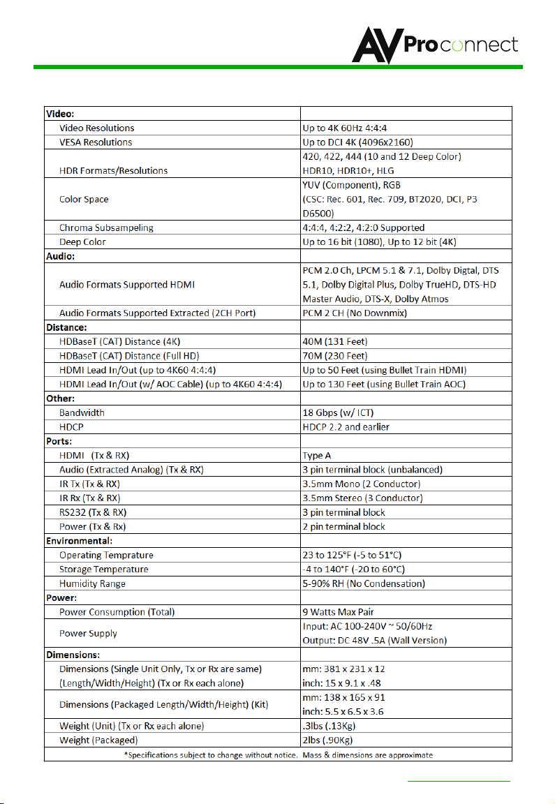
■ Specifications
AVProConnect ~ 3518 N Casco Ave. Sioux Falls, SD 57104~ 1.877.886.5112 ~ +1.605.274.6055 ~ [email protected]
pg. 6
Page 7
AC-EX40-444-KIT
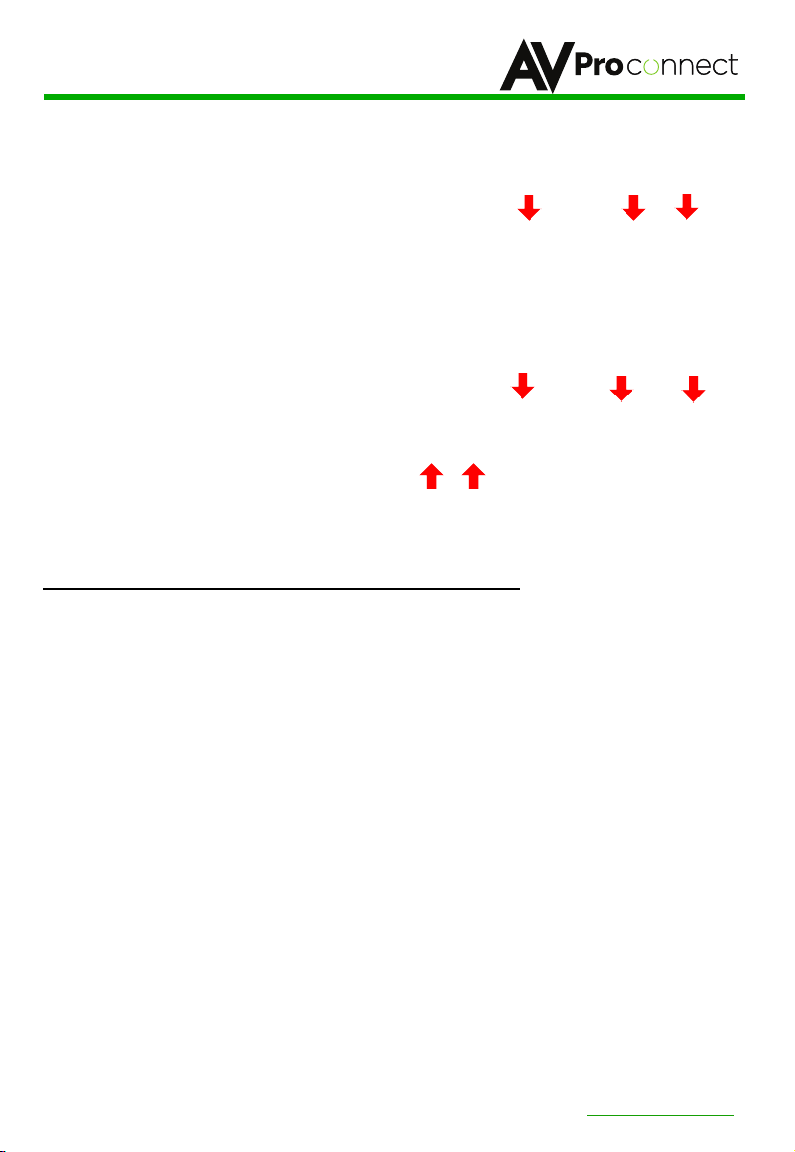
■ The Transmitter
Back
HDBaseT
RS232
IR Mode
Micro USB
(Firmware)
Front
IR Out
L/R Out (PCM Only)
IR In
HDMI In
Indicator Troubleshooting Lights on the Transmitter:
POWER - On the back by power supply input: (Red) This is an indicator that the power is connected. There
are only two states for light:
• Light Is On = Power supply is connected and functioning.
• Light Is Off = Power supply is not connected or there is no power present. (In order to have power: check
the power supply, USP, Outlet, etc...)
*LED also flashes when using the settings button described below.
STATUS - On front by HDMI Port: (Blue) This indicator shows that the HDMI source is connected. The
states are:
• Light Is On (Solid) = Sync w/ HDMI source is correct and solid.
• Light Is Flashing = The light flashes during the sync process. If it is flashing continuously, a picture may
not be present.
If the BLUE HDMI STATUS LIGHT is flashing, check the following:
1. The source. Plug it directly into the display to be sure it's functioning properly.
2. Try a longer HDMI cable. Some HDMI cables do not sync well at shorter lengths.
3. Set the EDID to state #1 (See below).
4. If these suggestions do not work, enable the "Test Pattern" (See Below). If you see the pattern, the
problem is between the source and the Transmitter, please try a different source.
5. Contact AVProConnect if these suggestions do not work.
AVProConnect ~ 3518 N Casco Ave. Sioux Falls, SD 57104~ 1.877.886.5112 ~ +1.605.274.6055 ~ [email protected]
pg. 7
Page 8

AC-EX40-444-KIT
Indicator Troubleshooting Lights on the Transmitter cont.:
LINK - Above RJ45 (HDBT) Port: (Green) This indicator shows that the AV HDBT link between the Tx and
Rx is in tact. This light should ALWAYS be solid. If this light is flashing or not present attempt following:
1. Check the length. The maximum distances are 40m (131ft) on 4K and 70m (230ft) on 1080P.
2. Remove any coils of cable and make sure that there is not excess cabling.
3. Bypass all patch panels and punch-down blocks.
4. Re-terminate connectors. Sometimes, even if a cable tester indicates the run is valid, something may be
slightly off.
5. Contact AVProConnect if these suggestions do not work.
STATUS- Above RJ45 (HDBT) Port: (Amber) This is an indicator showing that the power is present
between the Transmitter and Receiver. This light ALWAYS BLINKS steadily indicating everything is OK. If you
do not see this light, attempt the following:
1. Check the length. The maximum distances are 40m (131ft) on 4K and 70m (230ft) on 1080P.
2. Remove any coils of cable and make sure that there is not excess cabling.
3. Bypass all patch panels and punch-down blocks.
4. Re-terminate connectors. Sometimes, even if a cable tester indicates the run is valid, something may be
just slightly off.
5. Try powering from the Receiver instead of the Transmitter (See Receiver page for more about PoE
direction).
6. Contact AVProConnect if these steps do not work.
AVProConnect ~ 3518 N Casco Ave. Sioux Falls, SD 57104~ 1.877.886.5112 ~ +1.605.274.6055 ~ [email protected]
pg. 8
Page 9

AC-EX40-444-KIT
Functions & Setup of the Transmitter:
IR Mode Slide Switch:
IR-EYE - The IR Input will be configured to operate with an IR Receiver Eye.
I-PASS - The IR Input will be configured to safely operate with a direct connection from a control system
using a mono or stereo 3.5mm cable. This is protected from 3v-20v. Default mode is IR-EYE.
Using the Setting Button:
what is needed. The status light on the front will flash based on the selection. The selections are in series,
meaning, for example, if you are on selection 5 (listed below), you can come back later and press it again to
move you to 6, 7, 8, 1, 2, etc... An ink pen is best to press the button.
The POWER LED is the indicator LED.
EDID Management:
Quick press to select EDID
1. EDID BYPASS --- LED Flashes
2. 1
080P_2CH
3. 1080P_8CH --- LED Flashes 3 Times
4. 4K60HzY420_3D_2CH ---
5. 4K60HzY420_3D_8CH
6. 4K60Hz_3D_2CH_HDR---
7. 4K60Hz_3D_8CH_HDR --- LED Flashes 7 Times
8. USER EDID --- LED Flashes 8 Times
While in the USER EDID state (8), press and hold the setting button (for 4 seconds) in order to copy the EDID
from the connected display or downstream device to the user EDID and it will apply automatically.
Why do this?
This is commonly used when there is a need for a specific, known EDID that the installer may prefer. It can
also be used if you want to bypass an EDID of an AVR or another connected device. (IE, Plug the extender kit
directly into a display and COPY the EDID. Plug it back into an AVR that may not have a current/good EDID).
Scaler Setting:
While in ANY state besides the USER EDID state, press and hold the setting button (for 4 seconds) to toggle
the scaler mode. The options are:
(On Back) This is used to select a preferred IR Mode:
(On Back) The setting button can be pressed in different combinations based on
---
LED Flashes
1 Time (Default, from downstream device)
2 Times
LED Flashes
LED Flashes
--LED Flashes 6 Times
4 Times
5 Time
s
1. Normal Mode(ICT Mode) --- LED Flashes 1 Time
2. Down Scaler Mode (4K->2K) --- LED Flashes 2 Times
AVProConnect ~ 3518 N Casco Ave. Sioux Falls, SD 57104~ 1.877.886.5112 ~ +1.605.274.6055 ~ [email protected]
pg. 9
Page 10

AC-EX40-444-KIT
Functions & Setup of the Transmitter Cont.:
Test Pattern Generator:
Press and hold the setting button (for 4 seconds) while powering up the transmitter. You should see the
color bar pattern to the right on screen. When in this mode, you can quick press to toggle the resolution.
Quick press the setting button---Select the test pattern timing
• 1080P --- LED Flashes 1 Time (3 sets of color bars)
• 4K --- LED Flashes 2 Times (5 sets of color bars)
This can be useful for checking your cabling and for
troubleshooting. You can also ensure you have sufficient distance
based on the resolution as well.
AVProConnect ~ 3518 N Casco Ave. Sioux Falls, SD 57104~ 1.877.886.5112 ~ +1.605.274.6055 ~ [email protected]
pg. 10
Page 11
AC-EX40-444-KIT
■ The Receiver
HDBaseT
RS232
PoE Setting
Back
L/R Out (PCM Only)
HDMI
Front
IR Out
IR In
Indicator Troubleshooting Lights on the Receiver:
POWER - On the back by the power supply input: (Red) This indicator shows that the power is connected.
There are only two states for light:
• Light Is On = Power supply is connected and functioning
• Light Is Off = Power supply is not connected or no power present. - (In order to have power try checking
the power supply, USP, Outlet, etc...).
*LED flashes when using the settings button described below.
Out
Micro USB
(Firmware)
STATUS - On the front by HDMI port: (Blue) This indicator shows that the HDMI Display, Projector or
sink is connected. The states are:
• Light Is On (Solid) = Sync w/ HDMI source is valid and solid.
• Light Is Flashing = The light flashes during the sync process. If it is flashing continuously, you may still
have a picture, but it is indicating that the Rx is correcting a BE (Bit Error) to make the picture show on
the display.
Things to check if BLUE HDMI STATUS LIGHT is flashing AND you have no picture:
1. The display to make sure it is working properly (plug source or generator into display directly).
2. Try a different HDMI Input - Some have different functions/capabilities per display.
3. Try a longer HDMI cable. Some HDMI cables do not sync well at shorter lengths.
4. If these suggestions do not work, enable the "Test Pattern" (See Below). If you see the pattern, the
problem is before the Rx, please try a different source or EDID on the Tx. You can also try to scale the TX
to 1080P (see transmitter functions above).
5. Contact AVProConnect if these steps do not work.
AVProConnect ~ 3518 N Casco Ave. Sioux Falls, SD 57104~ 1.877.886.5112 ~ +1.605.274.6055 ~ [email protected]
pg. 11
Page 12

AC-EX40-444-KIT
Indicator Troubleshooting Lights on the Receiver cont.:
LINK - Above RJ45 (HDBT) Port: (Green) This indicator shows that the AV HDBT link between the
Transmitter and Receiver is in tact. This light will ALWAYS be solid. If this light is flashing or not present do the
following:
1. Check the length. The maximum distances are 40m (131ft) on 4K and 70m (230ft) on 1080P.
2. Remove any coils of cable and make sure that there is not excess cabling.
3. Bypass all patch panels and punch-down blocks.
4. Re-terminate connectors. Sometimes, even if a cable tester indicates the run is valid, something may be
slightly off.
5. Contact AVProConnect if these suggestions do not work.
STATUS- Above RJ45 (HDBT) Port: (Amber) This indicator shows that the power is present between the
Transmitter and Receiver. This light ALWAYS BLINKS steadily indicating everything is correct. If you do not see
this light, try the following:
1. Check the length. The maximum distances are 40m (131ft) on 4K and 70m (230ft) on 1080P.
2. Remove any coils of cable and make sure that there is not excess cabling.
3. Bypass all patch panels and punch-down blocks.
4. Re-terminate connectors. Sometimes, even if a cable tester indicates the run is valid, something may be
slightly off.
5. Try Powering from the Receiver instead of the Transmitter (See Receiver page for more about PoE
direction).
6. Contact AVProConnect if these suggestions do not work.
AVProConnect ~ 3518 N Casco Ave. Sioux Falls, SD 57104~ 1.877.886.5112 ~ +1.605.274.6055 ~ [email protected]
pg. 12
Page 13

AC-EX40-444-KIT
Functions & Setup of the Receiver:
PoE Mode Slide Switch:
There are two options (you are choosing where the power is ORIGINATING from):
• TX = You will need to power the TRANSMITTER, the receiver will be powered over the CAT Cable (Default).
• RX = You will need to power the RECEIVER, the transmitter will be powered over the CAT Cable (This is called
"Reverse Power").
Using the Setting Button:
on what you want to do. The status light on the front will flash based on your selection.
The POWER LED is the indicator LED.
Cascade Mode
This mode forces hot plug, which is useful when "daisy-chaining" extenders. It is also helpful for
troubleshooting if there are sync problems with devices.
To set this mode press and hold the setting button (for 4 seconds):
• Disable --- Power LED Flashes 1 Time
• Enable --- Power LED Flashes 2 Times
Test Pattern Generator:
Press and hold the setting button (for 4 seconds) while powering up the transmitter. The color bar pattern,
as seen to the right will appear. When in this mode, you can short press to toggle the resolution.
Quick press---Select the test pattern timing
• 1080P --- LED Flashes 1 Time
• 4K --- LED Flashes 2 Time
This is useful for checking cabling and for troubleshooting. It will check the
link between the Rx and the display/sink.
(On the back) This is used to select how you want to PoE is to be directed.
(On the back) The setting button can be pressed in different combinations based
AVProConnect ~ 3518 N Casco Ave. Sioux Falls, SD 57104~ 1.877.886.5112 ~ +1.605.274.6055 ~ [email protected]
pg. 13
Page 14
AC-EX40-444-KIT
■ RS-232 Configuration
RS2-32 can be used to pass control signals bi-directionally to & from any
RS-232 compatible device. This is commonly used to route control signals
in the following way:
1. Control System --> Display/Projector (ie, Power On/Off)
2. Display/Projector --> Control System (ie, Display Status, Volume
Status etc...)
3. When ultra long-range serial communication is needed at (think
concerts, live events). Use the extender.
The unit comes with 3 pin
connectors to allow for any wire an
integrator would like. The pin out
configuration Left=TX,
Center=Ground, Right=RX and
looks like this:
This is how the cable should look.
If using the AC-CABLE-3.5-DB9F
(Female) or AC-CABLE-3.5-DB9M
(Male), the colors will be the same.
With any other cable, please follow
Tx, G, Rx as shown above. A
RS-232 cable preparation diagram
is on the next page.
AVProConnect ~ 3518 N Casco Ave. Sioux Falls, SD 57104~ 1.877.886.5112 ~ +1.605.274.6055 ~ [email protected]
pg. 14
Page 15

AC-EX40-444-KIT
■ RS-232 Cable Prep
■ RS-232 Sample Application
AVProConnect ~ 3518 N Casco Ave. Sioux Falls, SD 57104~ 1.877.886.5112 ~ +1.605.274.6055 ~ [email protected]
pg. 15
Page 16

AC-EX40-444-KIT
■ IR Configuration
IR can be used in three ways:
1. From Rack (Control System Direct): Plug a MONO 3.5mm cable into
an emitter port of any control system directly into the "IR IN" port on the
AC-EX40-444 Transmitter to pass IR signals directly to the remote end.
NOTE - Be sure the IR MODE Slide Switch is set to "I-PASS" on the
Transmitter
2. From Rack (Using IR-EYE): Plug an IR-Receiver Eye into the "IR IN" of
the AC-EX40-444 Transmitter in order to pass infrared signals generated
from a device or IR Remote. NOTE - Be sure the IR MODE Slide Switch is
set to "IR-EYE" on the Transmitter.
3. From Remote End: Use an IR-Receiver Eye on the AC-EX40-444
Receiver (IR In Port) in order to send IR signals BACK to the rack and out
of the TRANSMITTER IR Out Port with an emitter.
AVProConnect ~ 3518 N Casco Ave. Sioux Falls, SD 57104~ 1.877.886.5112 ~ +1.605.274.6055 ~ [email protected]
pg. 16
Page 17

AC-EX40-444-KIT
■ IR Connections to AC-EX40-444-T (Transmitter)
■ IR Connections to AC-EX40-444-R (Receivers)
AVProConnect ~ 3518 N Casco Ave. Sioux Falls, SD 57104~ 1.877.886.5112 ~ +1.605.274.6055 ~ [email protected]
pg. 17
Page 18

AC-EX40-444-KIT
■ Audio Extraction on AC-EX40-444
A feature that is always active on the AC-EX40-444 (Tx and Rx) is
Audio Extraction. This feature extracts PCM Audio (2ch) from the
source device in order to be run to a separate amplifier or AVR. BOTH
of the audio ports are always active (on Tx & Rx). NOTE - These
ports ONLY work if the source is 2ch. If downmixing is needed, check
out AC-ADM-AUHD or AC-ADM-COTO.
To use the ports:
1. Simply plug a 3 pin terminal block into the port on the Tx or Rx
(both are always active) and make your own cable assembly.
2. There is an option to buy pre-made unbalanced 3-pin to RCA Female
cables from www.avprostore.com
NOTE: The source device needs to output PCM audio in order for the
feature to work. This can be done by using the on-board EDID
management or setting the source as such.
■ Audio Extraction Routing Diagram
AVProConnect ~ 3518 N Casco Ave. Sioux Falls, SD 57104~ 1.877.886.5112 ~ +1.605.274.6055 ~ [email protected]
pg. 18
Page 19

AC-EX40-444-KIT
■ Stereo Cable Preparation
NOTE: Pre-made audio cables can be purchased from
www.avprostore.com. The part number is: AC-CABLE-3PIN-2CH.
AVProConnect ~ 3518 N Casco Ave. Sioux Falls, SD 57104~ 1.877.886.5112 ~ +1.605.274.6055 ~ [email protected]
pg. 19
Page 20

AC-EX40-444-KIT
■ Maintenance
Clean this unit with a soft, dry cloth. Never use alcohol, paint thinner or
benzene to clean this unit.
Damage Requiring Service: The unit should be serviced by qualified
service personnel if:
The DC power supply cord or AC adaptor has been damaged;
Objects or liquids have gotten into the unit;
The unit has been exposed to rain;
The unit does not operate normally or exhibits a marked change in
performance;
The unit has been dropped or the housing has been damaged.
● Warranty
If this product does not work properly because of a defect in materials or
workmanship, AVProConnect (referred to as “the warrantor”) will, for the
length of the period indicated as below, (Parts/Labor (10)
Years)which starts with the date of original purchase (“Limited Warranty
period”), at its option either (a) repair your product with new or
refurbished parts, or (b) replace it with a new or a refurbished product. The
decision to repair or replace will be made by the warrantor.
During the “Labor” Limited Warranty period there will be no charge for labor.
During the “Parts” warranty period, there will be no charge for parts. You must
mail-in your product during the warranty period. This Limited Warranty is
extended only to the original purchaser and only covers product purchased as
new. A purchase receipt or proof of original purchase date is required for
Limited Warranty service.
AVProConnect ~ 3518 N Casco Ave. Sioux Falls, SD 57104~ 1.877.886.5112 ~ +1.605.274.6055 ~ [email protected]
pg. 20
Page 21

AC-EX40-444-KIT
● Warranty Limits and Exclusions
1) This Limited Warranty ONLY COVERS failures due to defects in
materials or workmanship, and DOES NOT COVER normal wear
and tear or cosmetic damage. The Limited Warranty ALSO DOES NOT
COVER damages which occurred during shipment, failures which are
caused by products not supplied by the warrantor, failures which result
from accidents, misuse, abuse, neglect, mishandling, misapplication,
alteration, faulty installation, set-up adjustments, misadjustment of
consumer controls, improper maintenance, power line surge, lightning
damage, modification, service by anyone other than a Factory Service
Center or other Authorized Service, or damage that is attributable to Acts
of God.
2) There are no express warranties except as listed under “limited
warranty coverage”. The warrantor is not liable for incidental or
consequential damages resulting from the use of this product, or
arising out of any breach of this warranty. (This excludes
damages for lost time, cost of having someone remove or re-install
an installed unit if applicable, travel to and from the service location,
loss of or damage to media or images, data or other recorded content.
The items listed are not exclusive, but are for illustration only.)
3) Parts and service, which are not covered by this limited warranty,
are the user's responsibility.
Adress:
3518 N Casco Ave , Sioux Falls, SD 57104
Tel: 877-886-5112 605-274-6055
AVProConnect ~ 3518 N Casco Ave. Sioux Falls, SD 57104~ 1.877.886.5112 ~ +1.605.274.6055 ~ [email protected]
pg. 21
Page 22
AC-EX40-444-KIT
Thank you for choosing AVProConnect!
Please contact us with any questions. We are happy
to be of service!
3518 N Casco Avenue ~ Sioux Falls, SD 57104
1-877-886-5112 ~ 605-274-6055
AVProConnect ~ 3518 N Casco Ave. Sioux Falls, SD 57104~ 1.877.886.5112 ~ +1.605.274.6055 ~ [email protected]
AVProConnect
pg. 22
 Loading...