

1
D
E
F
1 2
A
B
C
D
E
20.43
8
.
5
0
4
5
6
REV: DATE: CHANGE:
STATUS:
CUSTOMER:
SCALE @
DRAWN BY:
DRAWING NO:
TITLE:
A0
6
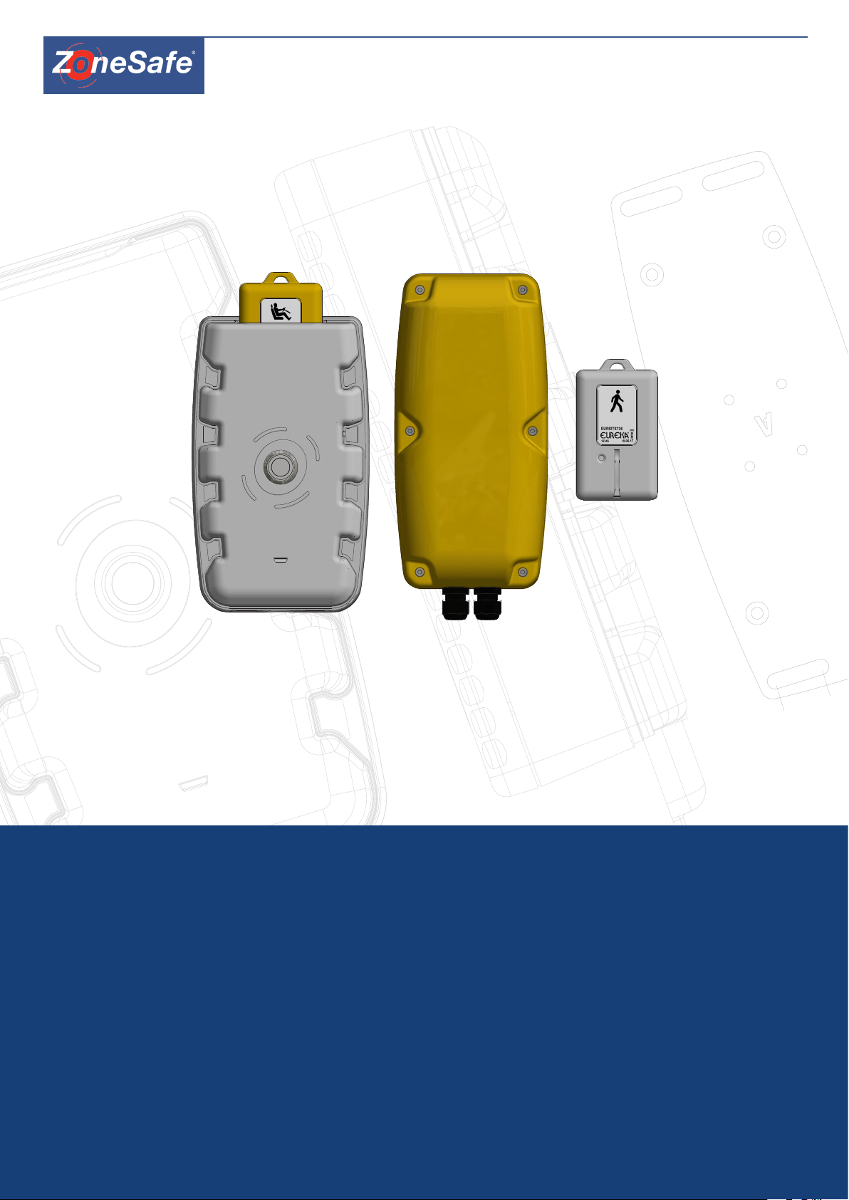
PROXIMITY WARNING & ALERT SYSTEMS
The ZoneSafe System
User Manual
www.zonesafe.net
sales@zonesafe.net

Document Name
ZoneSafe™ User Manual
Document Number
14/6784
Original Issue Date
17-07-2017
Issue No. Date of Issue Details of Changes
1 17/07/2017 Original Version
2
3
4
5
12/10/2017 updated images
12/10/2017 updated info
16/01/2018 DoC and FCC info added
23/01/2018 Added TufTag & Wireless Charger Information
Information in this document is subject to change without notice.
You do not have permission to reproduce, publish or share any part of this document either electronically or printed in part or
full without prior written consent from Avonwood Developments Ltd.
Contents
1 Introduction 4
2 What’s in the Box 4
3 How the System Works 4
4 System Components 5
4.1 Control Unit 5
4.3 Tags 6
4.4 Driver Tag 6
4.5 Wireless Tag Charger 6
4.5.1 Wireless Charger Charging Instructions 7
4.6 TufTags 7
4.6.1 TufTag Installation 7
4.7 Plus Tag Tester 7
4.8 Fixing 8
4.8.1 AMPS 8
4.8.2 Adapter plates 8
5 System Operation 9
5.3 Conguration 9
5.3.1 Connection 9
5.3.2 Summary 9
5.1 On Sequence 9
5.2 O Sequence 9
5.3.3 Conguration of Wi-Fi Proles 10
5.3.4 Conguration of Event Upload Settings 10
6 Hardware Installation 10
6.1 Requirements 10
6.2 Installation Considerations 10
6.2.1 Antenna Mounting 10
6.2.2 Distance between Antennas 11
6.2.3 Optimum Tag Position 12
6.3 Control Unit 12
6.4 Antenna Unit 13
6.5 Tags 13
7 Example Installation 13
8 Connections 14
8.1 Control Unit 14
8.2 Antenna Unit 15
8.2.1 Antenna Connections 15
8.2.2 Antenna Switches 15
8.3 Hardware Setup & Test 15
8.3.1 Installation of Units 15
8.3.2 Conrm Antenna Range 16
8.3.3 System Monitoring 16
9 System Specication 16
9.1 Control Unit 16
9.2 Antenna Unit 16
9.3 Tags 17
9.4 Tag Tester 17
10 Troubleshooting 17
11 WEEE Directive 17
12 Disclaimer 17
13 Approvals 18
14 FCC Compliance Information 18
14.1 Applicable FCC IDs: 18
15. Declarations of Conformity 19
15.1 Control Unit 19
15.2 Antenna Unit 20
15.3 Standard Tag 21
15.4 VibraTag 22
15.5 Plus Tag Tester 23
2 3
1 Introduction
ZoneSafe is a proximity warning and alert system for minimising collision risks to workers and assets in a working
environment.
The system uses Active RFID tags worn by workers or tted to assets. These are detected when in close proximity and activate
an audible visual alarm to indicate a risk to equipment operators.
Antenna units installed on the equipment produce a 360° detection zone. This is user congurable and can be set to detect
tags from a range of 3m to 9m distance. Using antenna units either single, multiple or overlapping detection zones can be set
up and congured depending on vehicle type and detection requirements.
Driver tags are placed into a tag holder located on the top of the control unit when the machine is operational. This enables
the drivers tag to be logged and prevent it from being detected. If a driver tag is not inserted in the holder, an audible alarm
will sound.
The system is typically installed on to materials handling equipment, industrial lift equipment, support equipment and heavy
plant.
Disclaimer:
As supplied the ZoneSafe system oers an indication to risk via audible and visual warnings only. ZoneSafe is not to be
used as a protective device, initiate or perform safety related functions or take over control to prevent accidents.
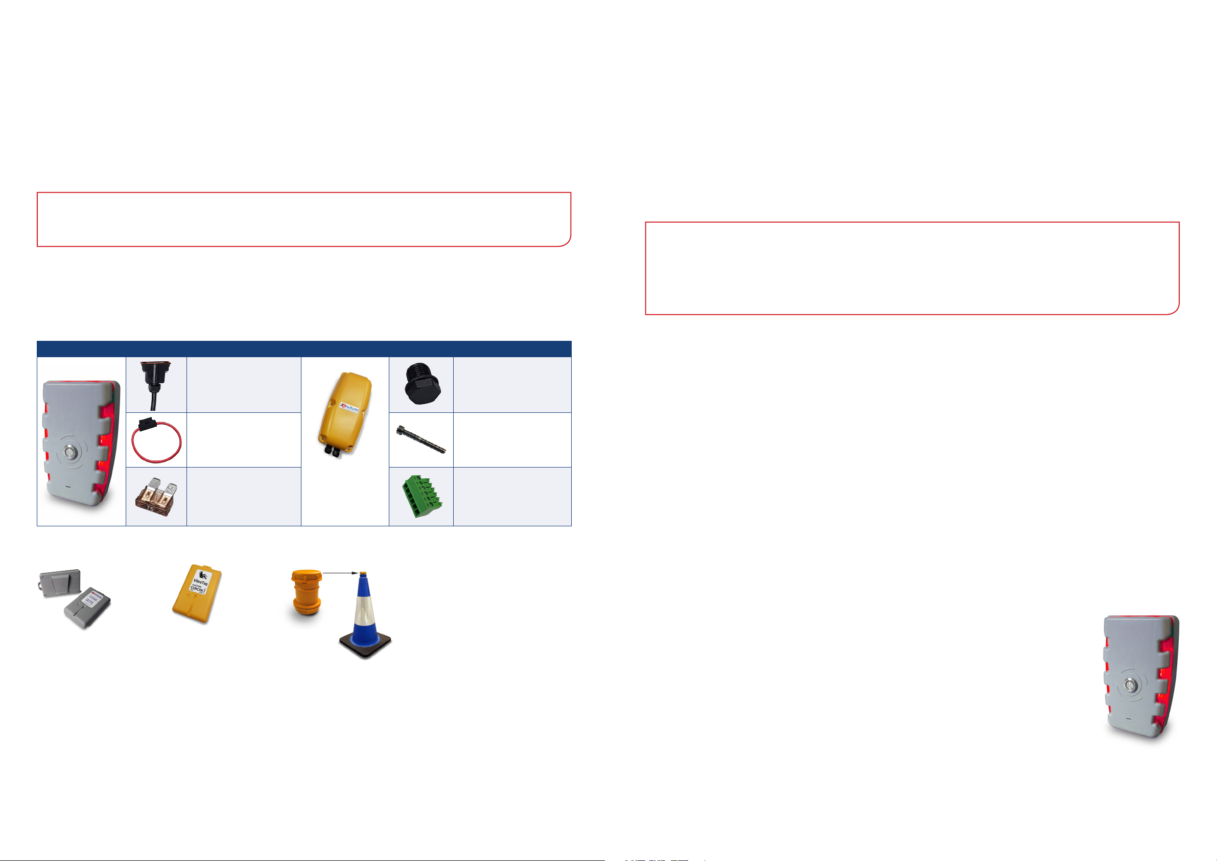
2 What’s in the Box
A standard system consists of:
Controller & Parts Antenna & Parts
Cable Loom & Connector
for Controller
Inline Fuse Holder
x2 per unit
7.5 Amp Blade Fuse
x2 per unit
Please note - tags are required for each ZoneSafe system to work. These are purchased seperately.
M16 Blanking Plug
(Note - part comes with controller)
M4 x 35mm Hex Screw
x6 per unit
6 Way Screw Terminal
x2 per unit
When a pedestrian tag or asset tag enters the 3m to 9m detection zone, an audible and visual alarm is activated from the incab control unit indicating to the equipment operator that a tagged person or asset is in close proximity to the vehicle.
The system maintains an event log and stores up to 4000 individual events. Events can be viewed either using an internet
browser connected to the control unit via Wi-Fi direct or by automatic upload via a Wi-Fi access point at my.zonesafe.net.
NOTE:
ZoneSafe must be tted and commissioned by an approved installer. No responsibility will be accepted for damage to
systems caused by incorrect installation or misuse.
Detection accuracy will depend on environmental and installation factors.
4 System Components
The ZoneSafe system comprises of the following standard components and accessories:
(for a more comprehensive range of our products please contact our sales team)
Standard Components
1. Control Unit
2. Antenna Unit
3. Standard Driver Tag - sold seperately
4. Standard Pedestrian Tag - sold seperately
Accessories (including but not limited to)
1. Plus Tag Tester (Tag battery level testing)
2. TufTag (Cone mounted tag for tagging assets)
3. VibraTag (Vibrating tag)
4. Fixing Plates (Installation)
5. Cloud Software (Identify, monitor and improve areas of risk such as near miss occurences throughout your work site)
4.1 Control Unit
Pedestrian Tag*
3 How the System Works
ZoneSafe is a tag based system using active radio frequency identication (RFID) technology. The system comprises of an
in-cab control unit with either single or multiple antenna units installed onto equipment, and active tags worn by workers or
tted to assets.
Three groups of active RFID tags are available, Driver Tags, Pedestrian Tags and Tuf Tags. A number of tag options are available
within these groups.
4 5
Driver Tag
TufTag
The Control unit provides the overall functionality of the system and acts as the user interface. The
unit contains a battery backed real-time clock for precisely logging tag detect events, internal memory
to store event data and a Wi-Fi interface for communication. A relay is available for additional external
sounders or beacons.
The Control unit is mounted in the driver cab next to the operator so it can be clearly visible at all
times. Audible alerts are emitted from a sounder located on the front, a light panel and button create
visual alerts and indicate various alarm states. The button can be congured to acknowledge the
detection of one or more tags.
The table of alarms indicates the types of alarms that the control unit will highlight. The alarm state demonstrates each alarm
colour sequence (note- black indicates the light is o).
Priority State Alarm Colour Alarm State Sounder Button Colour
1
2
3 4 5 6
REV: DATE: CHANGE:
STATUS:
CUSTOMER:
SCALE @
DRAWN BY:
REV:
DRAWING NO:
TITLE:
SHEET
A1
AS INDICATED IN ISO 2768-1
TOLERANCE CLASS
LINEAR = f
ANGULA
R = f
BROKEN EDGES = f
1 / 1
LOCATION OF CHARGING
COIL IN OUR TAG. NEEDS
TO BE CENTRAL TO THE
CHARGER TO PAIR.
INPUT 5V - 2A
CHARGER PULSES BLUE
WHEN CHARGING. IF NO
LIGHT COMES ON THEN
TAG IS ALREADY CHARGED.
INPUT 5V - 2A
CHARGER PULSES BLUE
WHEN CHARGING. IF NO
LIGHT COMES ON THEN
TAG IS ALREADY CHARGED.
1
2
3 4 5 6
2
3 4 5 6
3 4 5 6
1 2+ Pedestrian Red (Flash) Two Tone Fast Red
2 1 Pedestrian Red (Flash) Two Tone Slow Red
3 Reserved x x x x
4 System Error Pink (Flash) System Beep Red
5 No Ignition Red (Pulse) One Tone Red
6 No Driver Tag Red (Pulse) One Tone Red
7 WiFi Connected Blue (Pulse) x Green
8 Ok x x x Green
4.2 Antenna Unit
The Antenna Unit creates a detection zone around the vehicle or asset. Antennas should be tted
at appropriate locations to provide the optimum detection zone required (see 6.2.1 Antenna
Mounting).
Antenna units are linked (in series) to the system Control Unit. The number of antennas
required depends on the size of the vehicle and detection zone around it. Each antenna detection
zone can be adjusted between 3 - 9 metres (see 8.2.2 Antenna Switches).
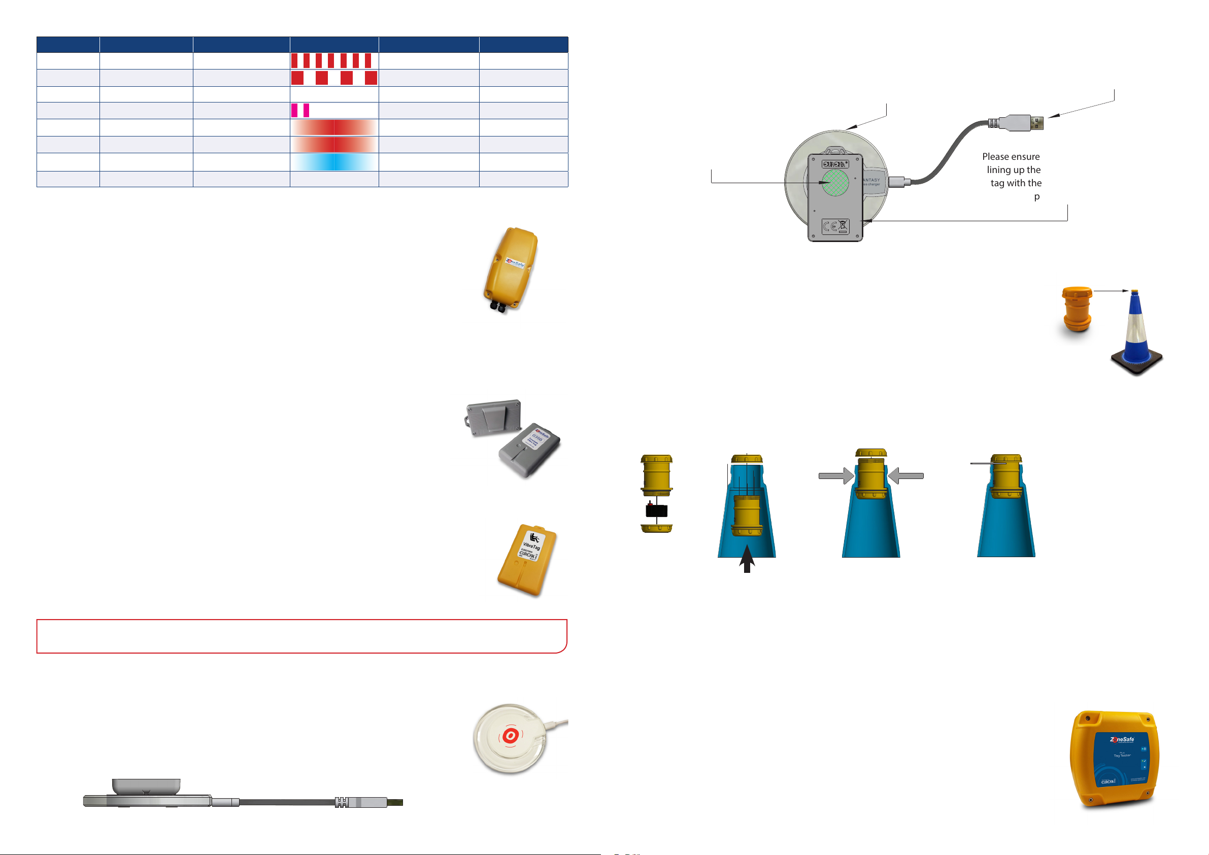
4.5.1 Wireless Charger Charging Instructions
Charger pulses blue when charging. If the light
doesn’t come on, the tag is fully charged.
Location of charging coil
in our tag. This needs to
be central to the charger
to pair.
Please ensure correct placement of tag
lining up the charging coil inside the
tag with the centre of the charging
4.6 TufTags
TufTag is our cone mounted active tag and integrates seamlessly with our ZoneSafe proximity
warning systems. Designed to protect static assets, the TufTag can be used in any situation
where a vehicle operator needs to be alerted to a potential hazard.
Input 5V - 2A
pad as shown.
4.3 Tags
Tags are worn by all personnel. When a tag enters the detection zone around a vehicle or asset, a
visual and audible alarm is provided from the in cab control unit to warn the machine operator.
Each tag is factory congured with a unique ID and can be used on any ZoneSafe enabled job site.
Tags within the proximity of a detection zone will be logged by the control unit. The data logged
from the tag includes its unique ID, date/time and battery status.
4.4 Driver Tag
A Driver Tag is required for the driver of the vehicle and for the system to work. The tag is placed into
the Control Unit (see 5.1 On Sequence), which not only arms the system but also masks itself from the
antenna. If the vehicle is started, and there is no tag present, the control unit will automatically alarm
emiting the no tag alarm tone.The driver must take the tag with them when they exit the vehicle.
NOTE: It is essential that all personnel on the work site wear a tag.
4.6.1 TufTag Installation
1. 2. 3. 4.
1 2 3 4
Section view of a cone
1. Connect and t the battery and tighten the cap.
2. Take o the top cap and t the tag through the neck of the cone from the inside. Hold the cone horizontally and extend
your arm to help push it through the neck or place on top of another cone to push the tag through.
3. Squeeze the neck of the cone and screw the top cap on.
4. Tighten the top cap with the card spanner tool.
4.5 Wireless Tag Charger
The wireless tag charger is used to charge any style of ZoneSafe rechargable tag such as the VibraTag
by simply connecting the charger via the mini USB cable to a power source and placing the tag on
top of the charging pad. For further information, please see the following section.
6 7
4.7 Plus Tag Tester
The Plus Tag Tester provides an easy way to test the status of any ZoneSafe / Eureka tag. We
recommend personnel check their tag battery status daily before entering the job site. The unit
reads a tag and displays the status of the battery using indicator LEDs. Daily use of the tag test
unit ensures tag batteries are always in a serviceable condition.

VIEW D-D
SCALE 1 :3
5
6
0.00
200mm
200.00
SECTION C-C
SCALE 2:1
5
FIXTURE
DETAIL A
SCALE 1 : 1
A
REV: DATE: CHANGE:
STATUS:
CUSTOMER:
SCALE @
DRAWN BY:
REV:
DRAWING NO:
TITLE:
A1
THIS DRAWING IS THE PROPERTY OF AND MA Y EMBODY PROPRIETARY INFORMATION
OWNED BY AVONWOOD DEVELOPMENTS LTD. IT IS PRO VIDED UNDER A CONFIDENTIAL
RELATIONSHIP FOR A SPECIFIC PURPOSE. THE REC IPIENT AGREES TO USE IT ONLY FOR
AS INDICATED IN ISO 27 68-1
UNLESS OTHERWISE STA TED
30.00
3
8
.
0
0
0.00
200mm
5
6
5
6
Indicator LED’s include:
• Blue Flash - Indicates The Plus Reader is turned on
• Quick Blue Flash - Indicates the reader has identied the tag
• Green Light - Indicates tag battery is good
• Red Light - Indicates low tag battery
4.8 Fixing
For xing of the Controller and the Antenna, use the AMPS conguration xings on the back of the devices or use one of the
adapter plates.
4.8.1 AMPS
Both the in-cab control unit and antenna have M5 threaded inserts in the AMPS conguration on the rear. Engagement depth
of machine screw must not exceed 8mm.
30.00
30.00
5 System Operation
5.1 On Sequence
• Place the driver tag into the slot
• Turn the vehicle ignition ON
to initialise the system
• If the Push Button LED = GREEN
then the system is operational
(for any other indication
see the alarm table)
• Detection Zone is now ACTIVE
5.2 O Sequence
• Turn the vehicle ignition OFF
• Remove the driver tag from the holder
• Button LED turns o
• Detection Zone is now INACTIVE
M5 PLAIN
M5 PLAIN
M5 INT TOOTH SHAKEPROOF
M5 INT TOOTH SHAKEPROOF
M5 X 0.8mm PITCH
0
0
.
8
3
38.00
You can use the hole conguration to attach a 1.5” Ball RAM Mount base and any conguration of RAM mount xtures. Holes
can be made directly on the vehicle and xing can be done from the back through the vehicle body and into the xings.
Thread lock and shake-proof washers are recommended - always fasten securely but do not over-tighten.
M5 X 0.8mm PITCH
THREAD LOCK
4.8.2 Adapter plates
An adapter plate is available for the Control unit and the Antenna. This xes to each unit via four countersunk M5 screws with
thread lock.
The adapter plates provide four legacy holes for customers who want to use the existing holes they made following a previous
ZoneSafe system installation. The plates also provide slots top and bottom which are large enough for M8 xings.
The method for attaching the Control unit will vary from vehicle to vehicle, if the adapter plate is to be used then the slots
allow for front xing or as an example a U bolt clamp can be fastened to them.
NOTE: If the ignition remains on and no driver tag
is in detected in the holder for a period of time,
the “No Driver Tag” alarm will be raised. This is
intended to prevent the vehicle being operated by
an un-authorised driver.
NOTE: If the ignition is o and the driver tag
remains left in the holder for a period of time, the
“No Ignition” alarm will be raised. This is intended
to remind the driver to take the tag when leaving
the vehicle.
5.3 Conguration
The ZoneSafe Wi-Fi Controller can automatically connect to Wi-Fi infrastructure networks and upload ZoneSafe event data to
the ZoneSafe Insight website. The Wi-Fi connection also permits a direct connection to allow conguration and monitoring of
the device via its integral Web Server.
5.3.1 Connection
The ZoneSafe Wi-Fi Controller broadcasts a SSID of ZoneSafe_XXXXXX where
XXXXXX is the device’s serial number, as printed on the product label. From
your device, view available Wi-Fi connections and select this network and click
Connect. Enter the default security key “ZONESAFE” and click OK
admin
When the connection has been established open a web browser and enter URL
http://192.168.0.1/ This is the address of the ZoneSafe Wi-Fi Controller. When
prompted for credentials, enter the default user name “admin” and password
“PASSWORD”.
PASSWORD
5.3.2 Summary
‘D’ Adapter Plate
tted to Controller Unit
8 9
‘A’ Adapter Plate
tted to Antenna
Exhaust ‘U’ Bolt Clamp
tted to Controller Unit
The Summary page displays the Control Unit and a separate box for each of the congured antennas. Click the Settings button
on the respective unit to open the conguration page for this unit.

5.3.3 Conguration of Wi-Fi Proles
5
6
5
6
DETAIL A
SCALE 1 : 1
VIEW D-D
SCALE 1 :3
REV: DATE: CHANGE:
STATUS:
CUSTOMER:
SCALE @
DRAWN BY:
REV:
DRAWING NO:
TITLE:
UNCONTROLLED
SHEET
A1
THIS DRAWING IS THE PROPERTY OF AND MAY EMBODY PROPRIETARY INFORMATION
OWNED BY AVONWOOD DEVELOPMENTS LTD. IT IS PROVIDED UNDER A CONFIDENTIAL
RELATIONSHIP FOR A SPECIFIC PURPOSE. THE RECIPIENT AGREES TO USE IT ONLY FOR
SUCH PURPOSE.
AS INDICATED IN ISO 2768-1
TOLERANCE CLASS
LINEAR = f
ANGULA
R = f
BROKEN EDGES = f
1 / 1
UNLESS OTHERWISE STATED
30.00
3
8
.
0
0
0.00
200mm
200.00
5
6
VIEW D-D
SCALE 1 :3
5
6
REV: DATE: CHANGE:
STATUS:
CUSTOMER:
SCALE @
DRAWN BY:
TITLE:
A1
200.00
ZoneSafe2™ User Manual
1.1.1 Distance between Antennas
Choose the size of the detection zone prior to fitting the system to the machine/object. The distance
between antennas should equal the detection zone minus 20%.
It is highly recommended to add at least one Wi-Fi network prole to your ZoneSafe device to allow automatic event
uploading and remote monitoring. The ZoneSafe Wi-Fi Controller can store up to 4 Wi-Fi network proles that it will
automatically connect to.
Click WI-FI from the menu. The device will perform a scan of Wi-Fi networks and display the list of networks found in order of
signal strength. Click the Add button on the row for the network you wish to add and enter the network passphrase when
prompted. Click Delete to remove the prole from the device.
5.3.4 Conguration of Event Upload Settings
Click Admin – Upload Settings from the menu.
The Upload Interval is specied in seconds. Set this value to zero to disable event uploading. After entering the required value,
click the Save button to apply the changes.
The other settings should only be changed under instruction from Avonwood Developments.
• No metal should be within 200mm of the top, bottom and sides of the antenna.
• No metal should be in front of the wakeup antenna, for example a grille.
200mm
0.00
200mm
6 Hardware Installation
Before installation please read the following guide lines to ensure that the system is correctly installed and provides optimum
performance.
NOTE: We recommend the installation of ZoneSafe™ is carried out by a fully authorised ZoneSafe™ installatio engineer.
The ZoneSafe Control Unit must be installed to be at least 20cm away from any person when in normal use.
6.1 Requirements
• 12V or 24V DC battery supply (protected by a 7.5A anti-surge fuse)
• 0V Earth location
• 12V or 24V DC ignition supply (protected by a 7.5A anti-surge fuse)
• Cable & tools
6.2 Installation Considerations
6.2.1 Antenna Mounting
• Antennas can be mounted vertically (best) or horizontally. For vertically mounted antennas in high positions, angle unit
downwards
6.2.2 Distance between Antennas
Choose the size of the detection zone prior to tting the system to the machine/object. The distance between antennas
should equal the detection zone minus 20%. Use the table to help set up an optimum detection zone. This setup will help
reduce lobe eects and provide an optimum detection zone.
Antenna Seperation vs Detection Zone
10
9
8
7
6
5
4
Detection Zone (M)
3
2
1
0
3.2 4 4.8 5.6 6.4 7.2
Max Antenna Seperation (M)
10 11

6.2.3 Optimum Tag Position
5
6
5
6
6.4 Antenna Unit
The optimum detection range of the tag can be achieved when the tag and wakeup antenna are level to each other. Changing
the angle of the antenna can overcome high mounting issues, but may reduce the eective read range.
Detection Zone
Antenna
Optimum Tag
Position Level to
Centre of Antenna
Tag
Detection Zone
Changing the Angle
of the Antenna can
Overcome High
Mounting Issues
Tag
Identify suitable locations for the Antenna Units and install the wiring loom from the Control Unit to the rst Antenna Unit
location. Then install the wiring from the rst antenna location to the second antenna location, then the second location to
third location etc.
The incoming power and data cable from the Control Unit enters via one cable gland and leaves via the other cable gland to
the next Antenna Unit in series.
6.5 Tags
Tags should be worn or attached vertically if possible to ensure best detection range. Tags can be worn using a lanyard, a
belt clip add on, an armband or integrated into PPE such as a high visibility vest. All personnel on the job site must wear an
working tag in order to be picked up by our system.
7 Example Installation
Depending on the size and shape of the vehicle, more than one antenna may need to be tted to provide a well dened
detection zone. Below illustrates a range of dierent vehicle types with at least one antenna tted to each vehicle. The larger
the vehicle, the more antennas will need to be tted to create an adequate detection zone around the vehicle. Antennas can
also be tted to moving parts such as the boom or dipper arm of a vehicle to create a moving detection zone.
One Antenna System
Fitted to Forklift Truck
Two Antenna System
Fitted to Bulldozer
6.3 Control Unit
The Control Unit should be located within the machine operator’s view and reach, but must not restrict the operator’s view of
the working area or any operational controls. The Control Unit must not be located within 75cm of an Antenna Unit. The unit
should preferably be installed in a vertical position or in clockwise tilt to allow water to freely drain.
Should you need to remove the tamper cover located at the bottom of the control unit covering the cable loom and
connection, please follow the instructions below.
Four Antenna System
Fitted to Shovel Loader
Gently insert
two small at
head drivers.
Angle screwdrivers
to release the clips
and lever cover out.
Detection
Zone
Five Antenna System Fitted to Excavator
with Antenna Fitted to Digger Arm
Detection
Zone
Antenna Location (Approx)
12 13

8 Connections
REV: DATE: CHANGE:
STATUS:
CUSTOMER:
SCALE @
DRAWN BY:
REV:
DRAWING NO:
TITLE:
SHEET
A0
THIS DRAWING IS THE PROPERTY OF AND MAY EMBODY PROPRIETARY INFORMATION
OWNED BY AVONWOOD DEVELOPMENTS LTD. IT IS PROVIDED UNDER A CONFIDENTIAL
RELATIONSHIP FOR A SPECIFIC PURPOSE. THE RECIPIENT AGREES TO USE IT ONLY FOR
SUCH PURPOSE.
AS INDICATED IN ISO 2768-1
TOLERANCE CLASS
LINEAR = f
ANGULA
R = f
BROKEN EDGES = f
1 / 1
UNLESS OTHERWISE STATED
REV: DATE: CHANGE:
STATUS:
CUSTOMER:
SCALE @
DRAWN BY:
DRAWING NO:
TITLE:
A0
REV: DATE: CHANGE:
STATUS:
CUSTOMER:
SCALE @
DRAWN BY:
DRAWING NO:
TITLE:
A0
NOTE: For 12V systems with long cable runs, a separate supply may be required to the Control Unit and each Antenna
Unit.
IMPORTANT: Ensure power is isolated & vehicle ignition is OFF before making connections.
8.2 Antenna Unit
Antenna Units are linked together using the IN and OUT 6 way headers, CONN2
and CONN3.
• Cable: 3 pair individually screened, Core: 7/0.2 (i.e. Belden 8777, Alpha
6010C, Cable Hub/ FS cables 2203PIFRD)
CONN2 CONN3
345
1
6
2
12345
6
8.1 Control Unit
Recommended ALPHA Wire 6010C
Mandatory Wiring:
Description Colour To
VBAT_IN Red Vehicle battery +ve
0V_IN Black Vehicle battery 0V
VIGN_IN White Vehicle ignition +ve
0V_OUT Red/Brown Wakeup CONN2/1
VIGN_OUT Red/Black Wakeup CONN2/2
SYNC_B Violet Wakeup CONN2/3
SYNC_A Yellow/Red Wakeup CONN2/4
RS485_B Yellow Wakeup CONN2/5
RS485_A Green/Red Wakeup CONN2/6
8.2.1 Antenna Connections
Pin numbering and descriptions for CONN2 and CONN3 are identical. CONN2 can be used for the outgoing cable and CONN3
for the incoming cable or vice-versa.
Wiring:
1
CONN2/3 Pin Number Description Colour*
1 0V_IN Black/Red
6
5
2
4
3
2 VIGN_IN Red
3 SYNC_B Black/White
4 SYNC_A White
5 RS485_B Black/Green
6 RS485_A Green
*Wiring Colours Based on Alpha Wire 6010C
3 Pair Foil Screened
(7/0.2,22AWG,.35mm²)
+
Antenna 1
SW2 = 1
Antenna 2
SW2 = 2
-
Blanking Plug or Connection
to 2nd, 3rd, 4th Antenna etc
8.2.2 Antenna Switches
Locate SW1, SW2 & SW3 inside antenna unit.
Using a trim tool or a small at bladed screw driver, turn SW1 clockwise to increase power or anticlockwise to decrease power.
Set SW1 to give the desired tag detection range.
SW2 – ADDRESS (1=rst antenna unit: must be numbered sequentially to the last)
SW3 – SYNC (OFF=external (driven from controller) ON=internal)
SW2
MIN. POWER
AUTO / WIFI
SW1
ADDRESS 1
Optional Wiring:
MAX. POWER
Description Colour
IN2+ Pink
IN1+ Blue
8.3 Hardware Setup & Test
IN2- Green
RL_NC Orange
RL_NO Brown
14 15
IN3+ Turquoise
IN3- Grey
IN1- Red/Blue
RL_COM White/Red
8.3.1 Installation of Units
Connect Control Unit and Antenna Unit cables before connecting to vehicle systems. Make sure switches SW1 to SW3 are set
on the Antenna Units as described in the previous section.

8.3.2 Conrm Antenna Range
9.3 Tags
Using an LED Test Tag (supplied separately), walk around the detection zone that has been set. An LED on the test tag will
illuminate when it is in the detection zone providing a visual illustration of the zone. The LED on the test tag may pulse
but should not be o for more than 1 second. As necessary, adjust TX power on each Antenna Unit to alter the size of the
detection zone. If one or more Antenna Units are installed incorrectly they can oppose each other and detection free zones
may exist.
8.3.3 System Monitoring
The system continuously monitors data communication & status from each Antenna Unit while in operation.
9 System Specication
9.1 Control Unit
ZoneSafe Control Unit
Electrical Voltage
Current Consumption
Memory
Mechanical Dimensions (incl. glands)
Material
Weight
Connectors
Relay (for additional
sounders / beacons)
Digital Input
Communications Wi-Fi IEEE 802.11b/g/n (2.4GHz)
Environment Ingress Protection
Temperature
12V - 24V DC nom (11-32V max)
1A max
4000 Events
180mm x 102mm x 58mm
ABS
0.5kg
IP D-type
N/O N/C
0.5A @125VAC, 2A@ 30VDC
3 x Opto-Isolated inputs
IP65
-10OC to +50OC
Contact our sales team for a more comprehensive guide to our range of tags. All our tags are hermetically sealed to withstand
the harshest environments.
9.4 Tag Tester
See Plus Tag Tester Manual 14/6667 for more information
10 Troubleshooting
Description Diagnosis Solution
Alarm does not mute. More than one tag in detection zone. Check detection zone for all tags.
With driver tag and ignition on, there is
a constant tone.
With no tag in the zone, the alarm still
pulses.
Alarm goes o in certain locations. Tag detection.
All vehicles in the area alarm at the
same time.
Why is the alarm a constant tone when
leaving the vehicle?
If a fault cannot be identied in the above table, or the solution does not resolve your fault, please contact your Zonesafe
qualied installation engineer.
It is the responsibility of the end user to keep a record of unique vehicle wake up ID if altered from the manufacture supplied
ID.
Wiring fault on ignition.
Driver tag is being detected.
Vehicle ID (wakeup address) is the
same.
Driver tag left in holder. Remove driver tag.
Check ignition and power is connected
correctly.
Contact a qualied installation
engineer, check driver search time and
masking eld.
Is there a tag behind a wall, on the
second oor or behind an obstacle?
Using Zonesafe software change
wakeup address.
11 WEEE Directive
9.2 Antenna Unit
ZoneSafe Antenna Unit
Electrical Voltage
Current Consumption
Mechanical Dimensions (incl. glands)
Material
Weight
Connectors
Mounting
Communications Wired RS485
Environment Ingress Protection
Temperature
Radio TX Frequency
RX Frequency
Range
16 17
12V - 24V DC nom (11-32V max)
2A max
245mm x 105mm x 90mm
ABS / PC
1.4kg
Nylon Glands
AMPS Conguration
IP67
-10OC to +50OC
125kHz
868.3MHz
TX: adjustable 3-9m approx
RX: 50m typ
The Waste Electrical and Electronic Equipment Directive (WEEE Directive) was introduced into UK law in
January 2007 by the Waste Electronic and Electrical Equipment Regulations 2006.
This product shall not be treated as household waste. It must be treated in accordance with the Waste
Electronic and Electrical Equipment Regulations 2006.
Avonwood Developments Limited is a WEEE registered producer WEE/EFO483SX.
12 Disclaimer
The ZoneSafe™ proximity warning systems manufactured by Avonwood Developments Limited are supplied as an audible
and/or visual alert system only. The ZoneSafe™ proximity warning system is not a protective device, it does not initiate or
perform safety related functions and it does not provide control to reduce risk.
ZoneSafe™ should not be used to replace proper job site organisation, safeguards, operator training and the application of

Reference & Date
Title
EN 300 220-2 V3.1.1 (2017-02)
Short Range Devices (SRD) operating in the frequency range 25
MHz to 1 000 MHz
EN 300 330 V2.1.1 (2017-02)
Short Range Devices (SRD); Radio equipment in the frequency
range 9 kHz to 30 MHz
Draft EN 301 489-1 V2.2.0 (2017-03)
ElectroMagnetic Compatibility (EMC) standard for radio equipment
and services
Draft EN 301 489-3 V2.2.1 (2017-03)
ElectroMagnetic Compatibility (EMC) standard for radio equipment
and services
Draft EN 301 489-17 V3.2.0 (2017-03)
ElectroMagnetic Compatibility (EMC) standard for radio equipment
and services
relevant vision standards that addresses safety and the safety of people on job sites.
15. Declarations of Conformity
Due to the nature of radio frequency, wireless communications and possible interference, data can never be guaranteed. Data
can be corrupted, have errors or be totally lost. Avonwood Developments Limited ZoneSafe™ systems should not be used in
situations where failure to transmit or receive data could result in damage of any kind to the user or any other party, including
but not limited to personal injury, death or loss of property. Avonwood Developments Limited accepts no responsibility for
damages of any kind resulting from errors in data transmitted or received using Avonwood’s ZoneSafe™ systems, or for the
failure of the Avonwood’s ZoneSafe™ systems to transmit or receive such data.
Avonwood Developments Limited accepts no liability for any and all direct, indirect, special, general, incidental, consequential,
punitive or exemplary damages including, but not limited to, loss of prots or revenue or anticipated prots or revenue arising
out of the use or inability to use any Avonwood Developments Limited products.
Information in this document is subject to change without notice.
13 Approvals
(a) For a Class A digital device or peripheral, the instructions furnished the user shall include the following or similar statement,
placed in a prominent location in the text of the manual:
NOTE: This equipment has been tested and found to comply with the limits for a Class A digital device, pursuant to part 15 of
the FCC Rules. These limits are designed to provide reasonable protection against harmful interference when the equipment
is operated in a commercial environment. This equipment generates, uses, and can radiate radio frequency energy and, if
not installed and used in accordance with the instruction manual, may cause harmful interference to radio communications.
Operation of this equipment in a residential area is likely to cause harmful interference in which case the user will be required
to correct the interference at his own expense.
Over the following pages you will nd Declarations of Conformity for each piece of equipment in The ZoneSafe Manual.
15.1 Control Unit
EU Declaration of Conformity (DoC)
We,
Company Name: Avonwood Developments Ltd
Address: Knoll Technology Centre, Stapehill Road,
Wimborne, Dorset. BH21 7ND
Declare that the DoC is issued under our sole responsibility and belongs to the following
product:
Product: ZoneSafe Standard Control Unit
Part Number: ZSR6783-EU
This device complies with part 15 of the FCC Rules. Operation is subject to the following two conditions: (1) This device may
not cause harmful interference, and (2) this device must accept any interference received, including interference that may
cause undesired operation.
14 FCC Compliance Information
Note: This equipment has been tested and found to comply with the limits for a Class A digital device, pursuant to part 15 of
the FCC Rules. These limits are designed to provide reasonable protection against harmful interference when the equipment
is operated in a commercial environment. This equipment generates, uses, and can radiate radio frequency energy and, if
not installed and used in accordance with the instruction manual, may cause harmful interference to radio communications.
Operation of this equipment in a residential area is likely to cause harmful interference in which case the user will be required
to correct the interference at his own expense.
Changes or modications to ZoneSafe™ systems not expressly approved by Avonwood Developments
Limited may void the user’s authority to operate the equipment.
The ZoneSafe Control Unit must be installed to be at least 20cm away from any person when in normal use.
14.1 Applicable FCC IDs:
The object of the declaration described above is in conformity with the relevant Union
harmonisation legislation:
Radio Equipment Directive 2014/53/EU
The following harmonised standards and technical specifications have been applied:
range 9 kHz to 25 MHz and inductive loop systems in the frequency
Signed for and on behalf of: Avonwood Developments Ltd
Place of issue: Knoll Technology Centre
th
Date of issue: 16
January 2018
ZoneSafe Control Unit 2ACWNZSR6783
ZoneSafe Antenna Unit 2ACWNZSA6782
VibraTag 2ACWNZST6687
Standard Tag 2ACWNZS6277
18 19
Name: Adrian Nash
Position: Engineering Manager
Signature:

Reference & Date
Title
EN 300 220-2 V3.1.1 (2017-02)
Short Range Devices (SRD) operating in the frequency range 25
MHz to 1 000 MHz
EN 300 330 V2.1.1 (2017-02)
Short Range Devices (SRD); Radio equipment in the frequency
range 9 kHz to 30 MHz
Draft EN 301 489-1 V2.2.0 (2017-03)
ElectroMagnetic Compatibility (EMC) standard for radio equipment
and services
Draft EN 301 489-3 V2.2.1 (2017-03)
ElectroMagnetic Compatibility (EMC) standard for radio equipment
and services
Draft EN 301 489-17 V3.2.0 (2017-03)
ElectroMagnetic Compatibility (EMC) standard for radio equipment
and services
15.2 Antenna Unit
Reference & Date
Title
EN 300 220-2 V3.1.1 (2017-02)
Short Range Devices (SRD) operating in the frequency range 25
MHz to 1 000 MHz
EN 300 330 V2.1.1 (2017-02)
Short Range Devices (SRD); Radio equipment in the frequency
range 9 kHz to 30 MHz
Draft EN 301 489-1 V2.2.0 (2017-03)
ElectroMagnetic Compatibility (EMC) standard for radio equipment
and services
Draft EN 301 489-3 V2.2.1 (2017-03)
ElectroMagnetic Compatibility (EMC) standard for radio equipment
and services
Draft EN 301 489-17 V3.2.0 (2017-03)
ElectroMagnetic Compatibility (EMC) standard for radio equipment
and services
15.3 Standard Tag
EU Declaration of Conformity (DoC)
We,
Company Name: Avonwood Developments Ltd
Address: Knoll Technology Centre, Stapehill Road,
Wimborne, Dorset. BH21 7ND
Declare that the DoC is issued under our sole responsibility and belongs to the following
product:
Product: ZoneSafe Antenna Unit
Part Number: ZSA6782-EU
The object of the declaration described above is in conformity with the relevant Union
harmonisation legislation:
Radio Equipment Directive 2014/53/EU
The following harmonised standards and technical specifications have been applied:
EU Declaration of Conformity (DoC)
We,
Company Name: Avonwood Developments Ltd
Address: Knoll Technology Centre, Stapehill Road,
Wimborne, Dorset. BH21 7ND
Declare that the DoC is issued under our sole responsibility and belongs to the following
product:
Product: Standard Tag
Part Number: ZST6735-EU
The object of the declaration described above is in conformity with the relevant Union
harmonisation legislation:
Radio Equipment Directive 2014/53/EU
The following harmonised standards and technical specifications have been applied:
range 9 kHz to 25 MHz and inductive loop systems in the frequency
Signed for and on behalf of: Avonwood Developments Ltd
Place of issue: Knoll Technology Centre
th
Date of issue: 16
January 2018
Name: Adrian Nash
Position: Engineering Manager
Signature:
range 9 kHz to 25 MHz and inductive loop systems in the frequency
Signed for and on behalf of: Avonwood Developments Ltd
Place of issue: Knoll Technology Centre
th
Date of issue: 16
January 2018
Name: Adrian Nash
Position: Engineering Manager
Signature:
20 21

Reference & Date
Title
EN 300 220-2 V3.1.1 (2017-02)
Short Range Devices (SRD) operating in the frequency range 25
MHz to 1 000 MHz
EN 300 330 V2.1.1 (2017-02)
Short Range Devices (SRD); Radio equipment in the frequency
range 9 kHz to 30 MHz
Draft EN 301 489-1 V2.2.0 (2017-03)
ElectroMagnetic Compatibility (EMC) standard for radio equipment
and services
Draft EN 301 489-3 V2.2.1 (2017-03)
ElectroMagnetic Compatibility (EMC) standard for radio equipment
and services
Draft EN 301 489-17 V3.2.0 (2017-03)
ElectroMagnetic Compatibility (EMC) standard for radio equipment
and services
15.4 VibraTag
Reference & Date
Title
EN 300 220-2 V3.1.1 (2017-02)
Short Range Devices (SRD) operating in the frequency range 25
MHz to 1 000 MHz
EN 300 330 V2.1.1 (2017-02)
Short Range Devices (SRD); Radio equipment in the frequency
range 9 kHz to 30 MHz
Draft EN 301 489-1 V2.2.0 (2017-03)
ElectroMagnetic Compatibility (EMC) standard for radio equipment
and services
Draft EN 301 489-3 V2.2.1 (2017-03)
ElectroMagnetic Compatibility (EMC) standard for radio equipment
and services
Draft EN 301 489-17 V3.2.0 (2017-03)
ElectroMagnetic Compatibility (EMC) standard for radio equipment
and services
15.5 Plus Tag Tester
EU Declaration of Conformity (DoC)
We,
Company Name: Avonwood Developments Ltd
Address: Knoll Technology Centre, Stapehill Road,
Wimborne, Dorset. BH21 7ND
Declare that the DoC is issued under our sole responsibility and belongs to the following
product:
Product: VibraTag Series
Type Designations: ZST6687-EU-P VibraTag – Pedestrian (EU)
ZST6687-EU-D VibraTag – Driver (EU)
ZST6687-EU-RP Rechargeable Tag – Pedestrian (EU)
ZST6687-EU-RD Rechargeable Tag – Driver (EU)
The object of the declaration described above is in conformity with the relevant Union
harmonisation legislation:
Radio Equipment Directive 2014/53/EU
The following harmonised standards and technical specifications have been applied:
EU Declaration of Conformity (DoC)
We,
Company Name: Avonwood Developments Ltd
Address: Knoll Technology Centre, Stapehill Road,
Wimborne, Dorset. BH21 7ND
Declare that the DoC is issued under our sole responsibility and belongs to the following
product:
Product Range: Plus Reader Series
Type Designations: ZSR6663-EU Plus Reader
ZSR6663-EU-T Plus Tag Tester
The object of the declaration described above is in conformity with the relevant Union
harmonisation legislation:
Radio Equipment Directive 2014/53/EU
The following harmonised standards and technical specifications have been applied:
range 9 kHz to 25 MHz and inductive loop systems in the frequency
Signed for and on behalf of: Avonwood Developments Ltd
Place of issue: Knoll Technology Centre
Date of issue: 16
th
January 2018
Name: Adrian Nash
Position: Engineering Manager
Signature:
range 9 kHz to 25 MHz and inductive loop systems in the frequency
Signed for and on behalf of: Avonwood Developments Ltd
Place of issue: Knoll Technology Centre
th
Date of issue: 16
January 2018
Name: Adrian Nash
Position: Engineering Manager
Signature:
22 23

1
D
E
F
1 2
A
B
C
D
E
20.43
8
.
5
0
4
5
6
REV: DATE: CHANGE:
STATUS:
CUSTOMER:
SCALE @
DRAWN BY:
DRAWING NO:
TITLE:
A0
6
ZoneSafe is a registered trademark of Avonwood Developments Ltd.
24
14 6784E
Avonwood Developments Ltd
Knoll Technology Centre,
Stapehill Road,
Wimborne,
Dorset, United Kingdom,
BH21 7ND
www.avonwood.co.uk
sales@avonwood.co.uk
+44 (0) 1202 868000
 Loading...