

PROXIMITY WARNING & ALERT SYSTEMS
Plus Reader / Tag Tester
User Manual
1

Contents
1. Introduction 4
2. System Components 4
3. How Does The System Work? 4
4. Installation 5
4.1. Location Consideration 5
4.2. Wiring Connection 6
4.3. PCB LED Indicators 7
4.4. Adjusting The Range 8
4.5. Fixing The Plus Reader To The Wall 8
4.6. Ball Mounting Option 8
4.7. PoE Daughter Board Kit 10
5. Using The Plus Reader / Tag Tester 11
Document Name
Discovery Plus User Manual
Document Number
14-6667
Original Issue Date
05/06/2017
Record of Changes
Issue No. Date of Issue Detail of Change
Draft 05/06/17
2 16/01/2018
6. Tags (see Tag User Manual) 12
7. Plus Reader Conguration 12
7.1. Network Connection 12
7.1.2. Internal Web Page 13
7.1.3. Network 13
7.1.4. Serial Port 14
7.1.5. Connection 14
7.2. General 15
7.3. Alarms 15
7.4. Cong File 16
7.5. Date & Time 16
7.6. Relays 17
7.7. Inputs 17
7.8. Admin 18
7.9. Web Server 18
8. Access Control 19
9. Specication 19
10. FCC Compliance Information 20
11. Declaration of Conformity 21
Information in this document is subject to change without notice.
You do not have permission to reproduce, publish or share any part of this document either electronically or
printed in part or full without prior written consent from Avonwood Developments Ltd.
2 3
1. Introduction
4. Installation
The Plus Reader is a cost eective solution for active RFID tagging applications using our Eureka RFID technology.
Designed for both internal or external applications the reader is housed in a rugged weatherproof enclosure.
Applications include personnel and asset tracking, access control and asset identication.
Each reader can be connected to a network enabling tag data to be logged and the device managed via local or
online services.
The unit is powered by a 24V DC supply or option for power over Ethernet (PoE) enabling easy installation where
multiple readers are set up on the same network.
Two onboard relays are available to operate auxiliary systems or an alarm on detection of a tag.
2. System Components
The Plus Reader is part of a complete RFID system comprising of the following standard components and accessories:
Standard Components
1. Plus Reader(s)
2. Tags (supplied seperately)
Before installation please read the following guidelines to ensure that the system is correctly installed and provides
optimum performance.
Minimum Requirements
• 24VDC (±5%) 10W supply protected by a 1A anti-surge fuse
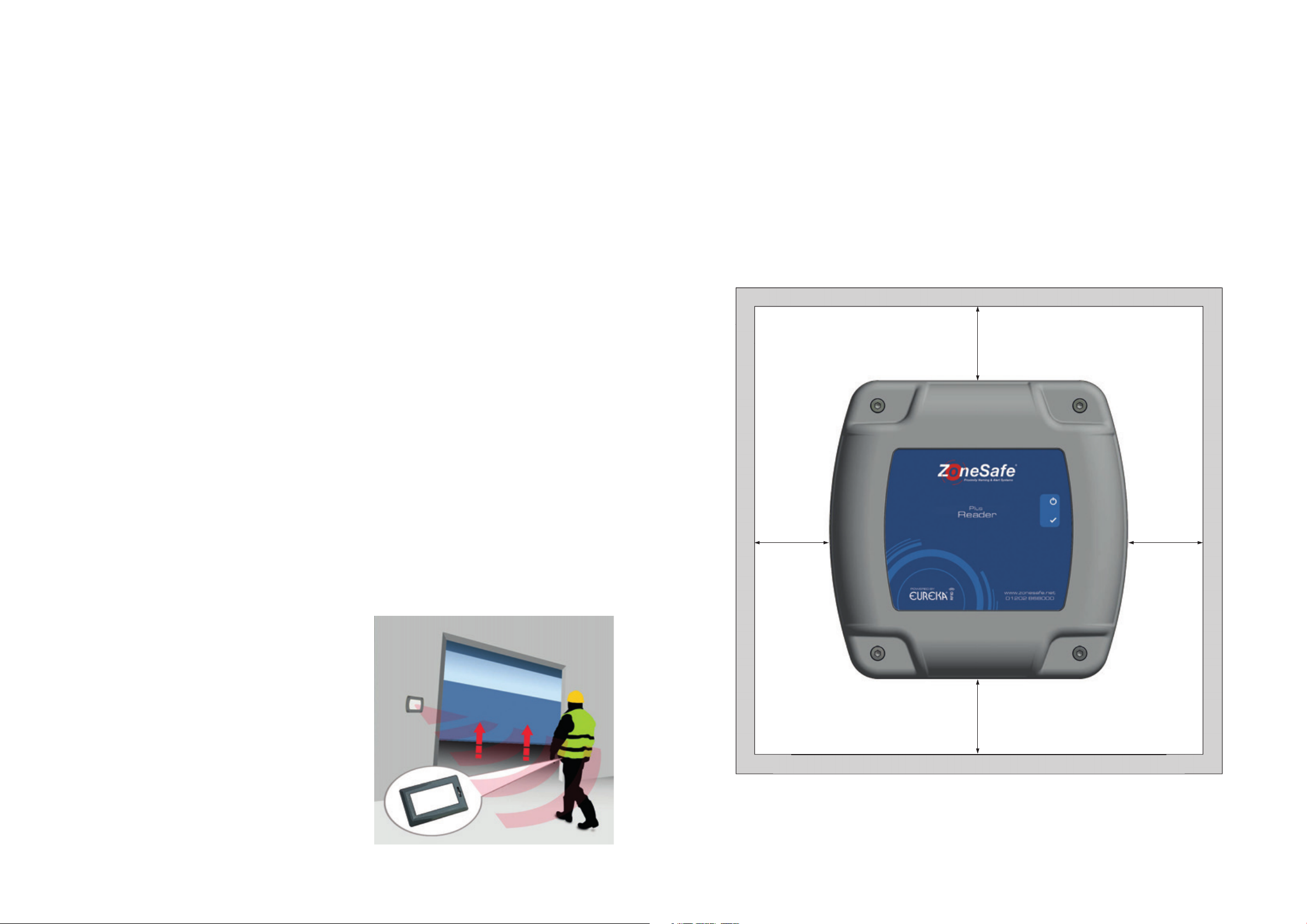
4.1. Location Consideration
Figure 1
200mm
Accessories
1. Power over Ethernet module
2. +24VDC Installation Power Supply
3. External Antenna
3. How Does The System Work?
The Plus Reader produces a user congurable detection zone between 1m to 4m (or upto 8m with external antenna)
which interacts with tags worn by personnel.
1. The Plus Reader creates a detection zone (1 - 4 metres)
around the unit.
2. The Plus Reader identies any tags entering the detection
zone.
3. When the tag is identied, the reader will carry out the
required function:
• Access Control - open door, barrier, gate or turnstile
• Alarm on tag detection
• Identify a particular asset
200mm 200mm
200mm
The example on the right illustrates a pedestrian worker walking
towards a Plus Reader. When the worker who is wearing a tag
enters the detection zone, the door automatically opens oering
a hands free access solution. This helps trac ow especially
when people are carrying equipment or pushing trolleys.
Installation Considerations
• No metal should be within 200mm of the top, bottom and sides of the reader (Figure 1)
• No metal should be in front of the antenna, for example a grille
4 5
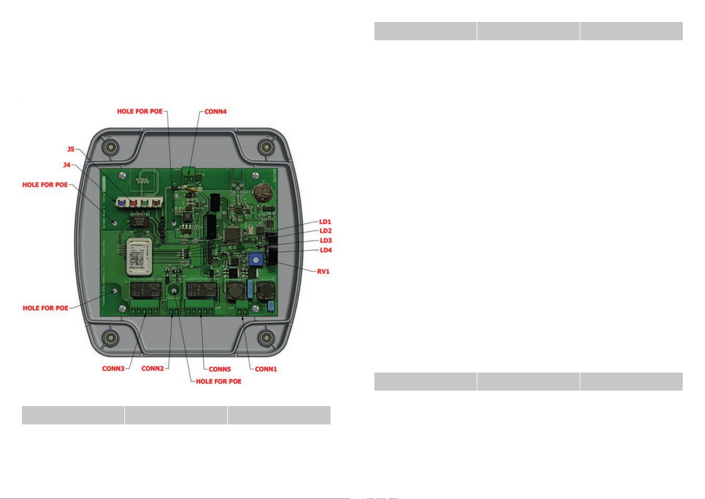
4.2. Wiring Connection
Connection Name Pin Number Description
The Plus Reader unit can be opened using an allen key and unscrewing the screw in each corner of the box revealing
the circuit board.
Below is a diagram (Figure 2) showing the location of each wiring connection.
Figure 2
CONN2: INPUT
CONN3: RELAY1 (5way) 1 0V
CONN4: POWER (2way) 1 +24V IN
CONN5: RELAY2 (5way) 1 0V
J4: ETHERNET (8way) 1 BLUE/WHITE
(2way for vault free contacts) 1 0V
2 Input +
2 Normally Open
3 Normally Closed
4 Common
5 +24v OUT (100mA max)
2 0V IN
2 Normally Open
3 Normally Closed
4 Common
5 +24V OUT (100mA max)
J5: HEADER FOR POE
4.3. PCB LED Indicators
Connection Name Description Function
LD1 Ethernet Link
2 BLUE
3 ORANGE/WHITE
4 ORANGE
5 GREEN/WHITE
6 GREEN
7 BROWN/WHITE
8 BROWN
LED is ON when Ethernet
port has a valid link
Connection Name Pin Number Description
LD2 Ethernet Speed
CONN1: ANT (2way for Antenna) 1 Antenna -
2 Antenna +
LD3 Ethernet Activity
LD4 Ethernet Duplex
6 7
LED is ON when Ethernet
is in 100Mbps mode
LED blinks when there is activity on
the Ethernet port
LED is ON when Ethernet
is in half duplex mode

4.4. Adjusting The Range
The range on the Plus Reader can be adjusted to detect tags between 1 and 4 metres away. The adjuster is marked
as RV1 in Figure 2 on the previous page. Using a at bladed screwdriver, turn the adjuster to change the size of the
detection zone.
• Turn the adjuster clockwise to increase the size of the detection zone
• Turn the adjuster anti-clockwise to decrease the size of the detection zone
Please note - Maximum and minimum range can be aected by the mounting location of the unit and power
supply ratings.
Figure 3
Top View
4.5. Fixing The Plus Reader To The Wall
The xing of the reader can be done from inside the unit through 4 holes drilled by the user as indicated in gure 3
on the opposite page.
Please note there is the option for mounting the reader using Ball mount xings via the four central threaded inserts
on the back as indicated in gure 3 on the opposite page.
To drill the xing holes:
• Place the back section of the reader so the drill point marks in the plastic are facing up. Make sure you have
something underneath where you are drilling so that in the event the drill bit goes too far through the plastic
you protect whatever is underneath from being damaged.
• Drill using a 4.2 to 4.5 mm spur point drill bit so that you have four holes which can take a 4mm diameter wood
screw or similar.
• Use a manual screwdriver when tightening the xing screws. Do not overtighten so as to reduce accidental
damage to the enclosure.
Cable glands can be installed either through the top or bottom at side of the enclosure rear section. Carefully drill
and enlarge holes to suit the glands as required.
Back View
Gland Size Drill Point Hole Size
M16 A 16mm
Bottom View
M20 B 20mm
4.6. Ball Mounting Option
The enclosure can be mounted via a ball mounting kit. Various
xing options are available and kits can be supplied by Avonwood.
For all mounting styles available you will need a ball mount base
kit, for this product we oer one kit for the ball mount.
EURIDM0000 – Ball Mount Base Kit
(Supplied with Fixings)
8 9

4.7. PoE Daughter Board Kit
5. Using The Plus Reader / Tag Tester
The PoE (Power Over Ethernet) Daughter Board is tted to the Reader PCB as shown in Figure 4 below.
Figure 4
Once the Plus Reader is installed and set up with the desired detection zone, the reader is ready to use. In order
for the reader to work as part of a system, everyone has to wear a tag. When the person wearing a tag enters the
detection zone, the reader will identify the tag and automatically carry out the required function - e.g. the door will
open.
Figure 6
The Plus Reader requires a 24VDC (±5%) 10W supply.
Dual N/O or N/C relay contacts are available for the
addition of external sounders, beacons or electromechanical locks. One digital input is provided
which can be used for monitoring a door sensor.
The reader retains time and date information, stores
event data, and provides Ethernet communications.
POWER INDICATOR LED
TAG READ INDICATOR LED
The Plus Reader oers visual and audible indicators
for both tag detection & reader status:
Please ensure that the plastic spacers are inserted correctly as per Figure 5 below. For further information about
ethernet wiring, please see page 7.
Figure 5
Figure 7
• Power LED (Blue ashes 1sec on/o = normal
operation)
• Tag Detect LED (Blue ashes 50ms On = tag
detected)
The Plus Tag Tester provides an additional way to
test the status of each tag worn by all personnel
before entering the job site. The unit reads a tag and
displays the status of the battery, using red or green
indicator LEDs and optional audible indicators. Daily
use of the tag test unit ensures tag batteries are
always in a serviceable condition.
POWER INDICATOR LED
TAG BATTERY LEVEL IS GOOD
TAG BATTERY LEVEL IS BAD
• Power LED (Blue ashes 1sec on/o = normal
operation)
• Battery OK LED (Green 3sec on = tag battery OK)
• Battery Low LED (Red 3sec on = tag battery Low)
10 11

6. Tags (see Tag User Manual)
7.1.2. Internal Web Page
Tags are worn by all relevant personnel. When a tag enters a detection zone a visual and audible indication is
provided. Each tag is factory congured with a unique identication number, when detected will be logged by the
reader. The data logged from the tag includes its unique number, date/time and any low battery warnings.
7. Plus Reader Conguration
The Plus Reader has an internal web page for conguration of device parameters and enabling additional features,
such as sending data to the My ZoneSafe website and managing Access Control. The internal web page can be
accessed via web browser using the IP address of the device.
7.1. Network Connection
All Plus Readers are shipped with DHCP enabled and a DHCP name using the Serial Number of the device. The Serial
Number can be identied from a label inside or on the back of the Plus Reader.
When the device is connected to a network port it will be assigned an IP address from your network’s DHCP server
if available. To discover the IP address assigned to a particular device you will need to use the Lantronix Device
Installer software, which can be downloaded from http://www.lantronix.com.
The webpage initially shows the status of various settings of the Plus Reader.
7.1.3. Network
1. Run the “Lantronix Device Installer” software from a PC on the same network as The Plus Reader. It
will automatically start searching for devices on the network.
2. Device Installer will show all devices located on your network. To identify the correct device from
its Serial Number, double-click a device with the name “xPico”. This will show a Device Info tab. Use
the DHCP Device Name property value to determine if this is the correct device.
The Network page allows conguration of the TCP/IP settings of the Plus Reader. You can use this page to congure
the appropriate settings for the Plus Reader on your network.
If any of these settings are changed, you must click the Save button and then the “Apply Settings” menu option,
then wait for the device to reboot. It may be necessary to use The Device Installer again to discover the updated IP
address of the device.
Having determined the correct device, note the IP Address assigned to it and open a web browser
to that address, for example http://10.0.0.121. When prompted for a username and password, leave
both elds blank and click OK.
12 13

7.1.3. Serial Port
7.2. General
The Serial Port page allows conguration of internal serial port settings of the device.
These settings should not be modied unless instructed by Avonwood Developments. Changing these
settings could make your Plus Reader inoperable.
The General Settings page contains the primary user congurable parameters of the device.
A tooltip is displayed when hovering the cursor over each setting explaining its purpose. Click the Save button for
changes to take eect.
7.1.4. Connection
The Connection Settings page allows conguration of the TCP settings used for sending event data and tag read
data to the My ZoneSafe website. The local port can be changed if necessary to be compatible with your network
rewall conguration.
The remote IP is used with the web server settings to send event data and tag read data to the My ZoneSafe website.
These settings should not be modied unless instructed by Avonwood Developments.
7.3. Alarms
The Alarms page contains the alarm settings for the device.
A tooltip is displayed when hovering the cursor over each setting explaining its purpose. Click the Save button for
changes to take eect.
14 15

7.4. Cong File
7.6. Relays
The Cong File page contains the ability to export the conguration of the device or import a new conguration. Click
“Save Cong” to obtain an XML conguration le of the current parameter settings of your device. Use the “Import
Cong” button to load a selected XML conguration le into the device. Normally this should only be required when
advised by Avonwood Developments.
The Relays page contains the relay settings for the device.
A tooltip is displayed when hovering the cursor over each setting explaining its purpose. Click the Save button for
changes to take eect.
7.5. Date & Time
The Date & Time settings allow you to check and set the current date/time on the device. This value will be used to
record the time of events and tag reads. Click the Save button for changes to take eect.
7.7. Inputs
The Inputs page contains the input settings for the device.
A tooltip is displayed when hovering the cursor over each setting explaining its purpose. Click the Save button for
changes to take eect.
16 17

7.8. Admin
8. Access Control
The Admin web page allows advanced conguration of the Plus device to be undertaken. This feature should not be
used unless instructed by Avonwood Developments.
The Access Control web page displays a list of RFID tag numbers that are permitted if the Access Control Mode is
enabled in the General settings (See section 11). Tag numbers can be manually added or removed using this page.
The Clear All Tags button will remove the complete list of permitted tags from the device.
If the “Get Access List Enable” option is enabled, the software will periodically request a list of permitted tag numbers
for this device from the My ZoneSafe website.
7.9. Web Server
The Web Server page allows conguration of the HTTP settings for sending event data and tag read data to the My
ZoneSafe website and retrieval of Access Control settings. A tooltip is displayed when hovering the cursor over each
setting explaining its purpose. Click the Save button for changes to take eect.
9. Specication
Specication Type Description
Electrical
Mechanical
Voltage
Power
Dimensions
Connectors
Relay
24V DC Input (±5%)
<10W
155mm x 155mm x 60mm
IP68
2x Rated Current 1A @ 30V
O
-10
C to +55OC
1 x
IP67
Input
Communication Ethernet 10-BaseT or 100-BaseTx
Ingress Protection
Environment
Temperature
18 19

10. FCC Compliance Information 11. Declaration of Conformity
Reference & Date
Title
EN 300 220-2 V3.1.1 (2017-02)
Short Range Devices (SRD) operating in the frequency range 25
MHz to 1 000 MHz
EN 300 330 V2.1.1 (2017-02)
Short Range Devices (SRD); Radio equipment in the frequency
range 9 kHz to 30 MHz
Draft EN 301 489-1 V2.2.0 (2017-03)
ElectroMagnetic Compatibility (EMC) standard for radio equipment
and services
Draft EN 301 489-3 V2.2.1 (2017-03)
ElectroMagnetic Compatibility (EMC) standard for radio equipment
and services
Draft EN 301 489-17 V3.2.0 (2017-03)
ElectroMagnetic Compatibility (EMC) standard for radio equipment
and services
Note: This equipment has been tested and found to comply with the limits for a Class A digital device, pursuant to
part 15 of the FCC Rules. These limits are designed to provide reasonable protection against harmful interference
when the equipment is operated in a commercial environment. This equipment generates, uses, and can radiate
radio frequency energy and, if not installed and used in accordance with the instruction manual, may cause harmful
interference to radio communications. Operation of this equipment in a residential area is likely to cause harmful
interference in which case the user will be required to correct the interference at his own expense.
We,
EU Declaration of Conformity (DoC)
Changes or modications to ZoneSafe™ systems not expressly approved by Avonwood Developments
Limited may void the user’s authority to operate the equipment.
FCC ID: 2ACWNZSR6663
Company Name: Avonwood Developments Ltd
Address: Knoll Technology Centre, Stapehill Road,
Wimborne, Dorset. BH21 7ND
Declare that the DoC is issued under our sole responsibility and belongs to the following
product:
Product Range: Plus Reader Series
Type Designations: ZSR6663-EU Plus Reader
ZSR6663-EU-T Plus Tag Tester
The object of the declaration described above is in conformity with the relevant Union
harmonisation legislation:
Radio Equipment Directive 2014/53/EU
The following harmonised standards and technical specifications have been applied:
range 9 kHz to 25 MHz and inductive loop systems in the frequency
Signed for and on behalf of: Avonwood Developments Ltd
Place of issue: Knoll Technology Centre
th
Date of issue: 16
January 2018
Name: Adrian Nash
Position: Engineering Manager
20 21
Signature:

Notes / Useful information
22 23

POWERED BY
24
Avonwood Developments Ltd
Knoll Technology Centre,
Stapehill Road,
Wimborne,
Dorset, United Kingdom,
BH21 7ND
14 6667B
www.avonwood.co.uk
sales@avonwood.co.uk
+44 (0) 1202 868000
 Loading...