

Page 1
Wireless Sender
Full HD Full HD Full HD Full HD Full HD
Full HD
REV. C. 1.0
English
User’s manual
(COMPOSITE Model)
www.AVL21c.com
Page 2
Contents
Caution for Safety
Caution for Safety 4.....................................
Introduction
Product Introduction
Major Feature
Package Contents
Package Contents 7.....................................
Operation Control & Function
Transmitter Front
Transmitter Rear
Receiver Front
Receiver Rear
Remote Control
Installation
WiFi Transmitter / Receiver installation order & how to install
PLC Transmitter / Receiver installation order & how to install
Operation checklist from LED status
Device with HDMI : Connect through HDMI port
How to install IR-Flasher
LAN Transmitter / Receiver installation order & how to install
...................................
........................................
.....................................
......................................
.......................................
........................................
......................................
........
........
.........................
................
.................................
........
English
6
6
8
8
9
9
10
11
12
13
14
15
16
Product Specication
Specication
Supported port
Video Format Supported
Audio Format Supported
Change WiFi Frequency
Factory Reset
Software upgrade
........................................
.......................................
................................
................................
.................................
........................................
.....................................
Q & A
Q & A 22.............................................
17
18
19
20
20
20
21
3
Page 3
Caution for Safety
Please read this user’s manual carefully before using the product.
English
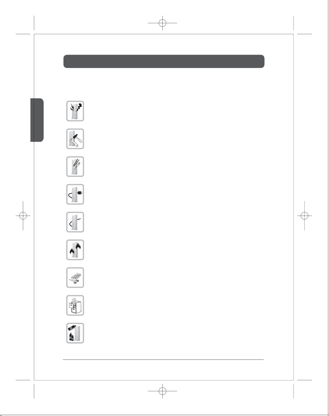
If there is any strange sound, smoke or odor, pull the cable o immediately.
(It may cause re or electric shock)
Do not disassemble.
(It may cause re or electric shock.)
Do not put any sharpen object into the venting hole of the product.
(It may cause re or electric shock.)
Ensure to plug the product rmly.
(It may cause overheating or re if it plugs unstably.)
Ensure not to use the damaged cable.
( It may cause re or electric shock.)
Keep the product away from heaters or stoves.
(It may cause a re.)
Keep the battery of remote control out of reach of children.
Do not place the production on a bed, sofa or inside a closet that is not good for
ventilation.
(It may cause overheating or re.)
Do not use the product in close distance from the inammatory substance or combustible
spray.
(It may cause re.)
4
Page 4
Caution for Safety
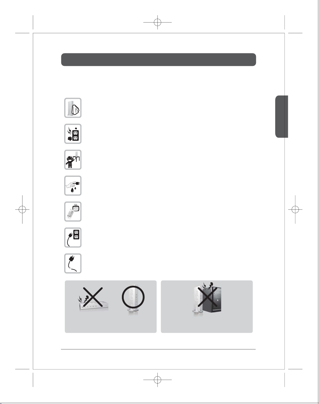
Always wipe the product o with soft fabric, not water mop.
(Water may come inside the product through the venting hole, and it may cause
electric shock.)
Keep clean the power plug and the outlet.
(Dirt may cause a short circuit and re.)
Keep the product out of reach of children.
Don’t unplug the power cord with a wet hand.
(It may cause electric shock.)
The heat and humidity may cause the damage to the remote control.
Unplug the power cord if you don’t use the product for a long time.
(Dirt may cause heat, re or electric shock.)
Ensure not to be damaged to the power cord.
(Damaged power cord may cause re or electric shock.)
English
Please use the devices in a stand position with stand cradle.
When you use the devices in laid down, it may cause the malfunction
of the devices because of the raise temperature of internal.
Don't place the devices near the heating product.
It may cause the malfunction of the devices because of the raise
Place the product 5cm apart from the wall for ventilation of heat.
temperature of internal.
5
Page 5
English
Introduction
■
Product Introduction
itrio, using WiFi wireless solution, is the device for sending 1920x1080 Full HD video sources to other
location in your house. Once you connect Full HD video sources such as Set top box, Blu-ray player,
Multi media player, DVD player or PC to the transmitter and connect the display device to the receiver,
you can enjoy wirelessly Full HD video anywhere in your house.
itrio uses IEEE802.11n draft 2.0 standard WiFi technology for wireless connection. In case the wireless
connection is interfered, you can use PLC (power line communication) modem without additional
cable installation. You can also enjoy itrio through a LAN cable connection via LAN port.
■
Major Feature
●
1080p60 Full HD encoding/decoding with H.264 Baseline Prole (Level 4.2)
●
Low latency
- Latency of encoding-decoding in 1080p60 HD: Within 30ms
●
Supports both digital(HDMI) and analog(RGB, Component, D-Sub) video/audio
●
Supports Wireless or Wireline
- IEEE 802.11n 5 GHz WiFi
- Power line communication (PLC) modem
- LAN connection
●
Internal Antenna (Supporting MIMO)
●
HDMI-v1.3 (HDCP-v1.1) compliant.
●
Supports both DTV & VESA standards
- DTV : 1920x1080i60/p60, 1280x720p60, 720x480i60/p60
- VESA : WSXGA+(1680x1050), SXGA(1280x1024), WXGA(1280x800), XGA(1024x768),
SVGA(800x600), VGA(640x480)
6
Page 6
Package Contents
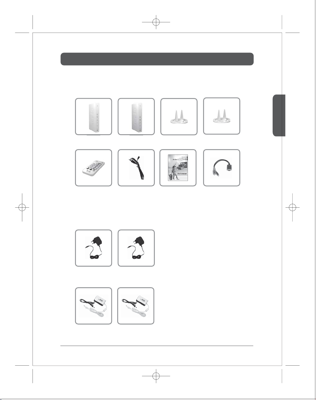
Before you use the product, check the following components are all present.
※
■
Components
Transmitter Receiver Stand1 Stand2
English
Remote Control
■
Adapter by model
- HD-W100 / HD-L100
Adapter1 Adapter2
- HD-P100
PLC1 PLC2
IR-Flasher
User’s Manual Component adaptor
7
Page 7
Operation Control & Function
■
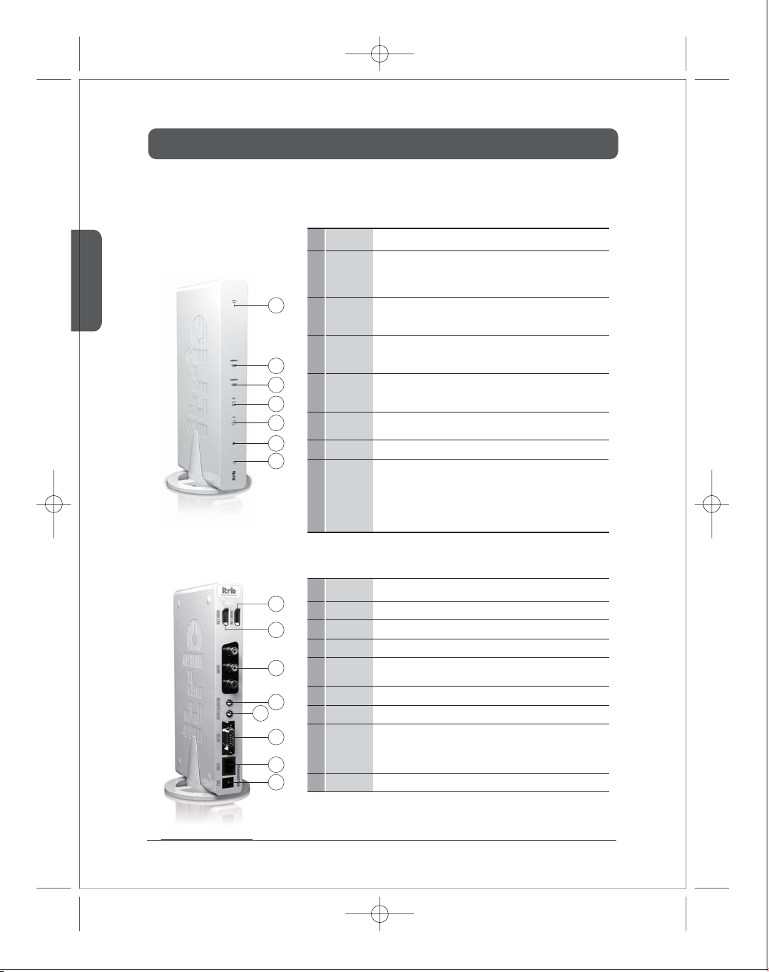
Transmitter Front
English
■
Transmitter Rear
Description
○
Blink : System booting or establishing link between the transmitter and the receiver.
○
1
Power/Link LED
1
2
HDMI1
3
2
3
4
5
6
7
HDMI2
4
PC
5
AV
6
IR window
Power and
7
Source Button
Quick Blink : Software upgrading or wireless/LAN mode switching.
○
On : Finish of link establishment is completed between the transmitter and the
receiver.
It will be on when the HDMI1 port is selected for the video input.
If the cable is not connected or video signal is not fed into properly, LED will blink.
It will be on when the HDMI2 port is selected for the video input.
If the cable is not connected or video signal is not fed into properly, LED will blink.
It will be on when the PC-IN port is selected for the video input.
If the cable is not connected or video signal is not fed into properly, LED will blink.
It will be on when the AV-IN port (Composite or Scart) is selected for the video
input.
IR receiving window from remote control.
○
Press it shortly to turn the power on.
○
When power on,
--Press shortly : Press to select the video input source. Each press the power
button will cycle through the available video input "HDMI1→ MHMI2→ PC
AV →HDMI1" in sequence.
→
Press longer : Press and hold more than 3 seconds to turn the power o.
Description
1
2
3
4
5
HDMI1-IN
1
HDMI2-IN
2
3
AV-IN
4
IR-OUT
5
PC AUDIO-IN
PC-IN
6
6
LAN
7
7
8
8
DC
HDMI 1 input port (correspond to ‘HDMI1’ on the remote control)
HDMI 2 input port (correspond to ‘HDMI2’ on the remote control)
Composite or SCART input port (correspond to ‘AV’ on remote control)
Connect IR Flasher to control external devices which are connected to the
transmitter.
Stereo Audio input port
Support component input through component gender.
It will be used for the following feature
○
Connection to PLC modem
○
Direct connection to LAN cable
○
Connection to PC for the system conguration setting
Power input port
Function
Function
8
Page 8
Operation Control & Function
■
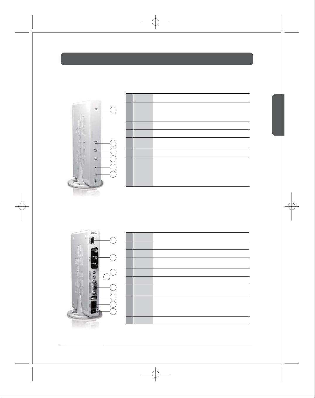
Receiver Front
■
Receiver Rear
Description
○
Blink : System booting or establishing link between the transmitter and the receiver.
○
1
1
Power/Link LED
HDMI
3
COMPO
4
2
3
AV
IR window2IR receiving window from remote control.
5
4
5
6
1
2
3
4
5
Power and
6
Source Button
Description
HDMI-OUT
1
2
AV-OUT
3
IR-IN
AUDIO-OUT
4
COMPONENT-OUT
5
6
USB
6
7
LAN
7
8
8
DC
Quick Blink : Software upgrading or wireless/LAN mode switching.
○
On : Finish of link establishment is completed between the transmitter and the
receiver.
It will be on when the HDMI-OUT port is selected for the video output.
It will be on when the COMPONENT-OUT port is selected for the video output.
It will be on when the AV-OUT port (composite or SCART) is selected for the video
output.
○
Press it shortly to turn the power on.
○
When power on,
--Press shortly : Press to select the video input source. Each press the power
button will cycle through the available video input "HDMI → COMPO →AV
HDMI " in sequence.
→
Press longer : Press and hold more than 3 seconds to turn the power o.
HDMI output port
Composite or Scart output port
Connect additional IR Extender in order to extend receiving the
remote control.(purchase separately)
Stereo Audio output port
Component output port
This USB port is for software upgrade.
(For more information, please refer to Software upgrade on page 17. )
LAN cable will be used for the following feature
○
Connection to PLC modem
○
Direct connection to LAN cable
○
Connection to PC for the system conguration setting
Power input port
Function
English
Function
9
Page 9
Operation Control & Function
■
Remote control
English
Description
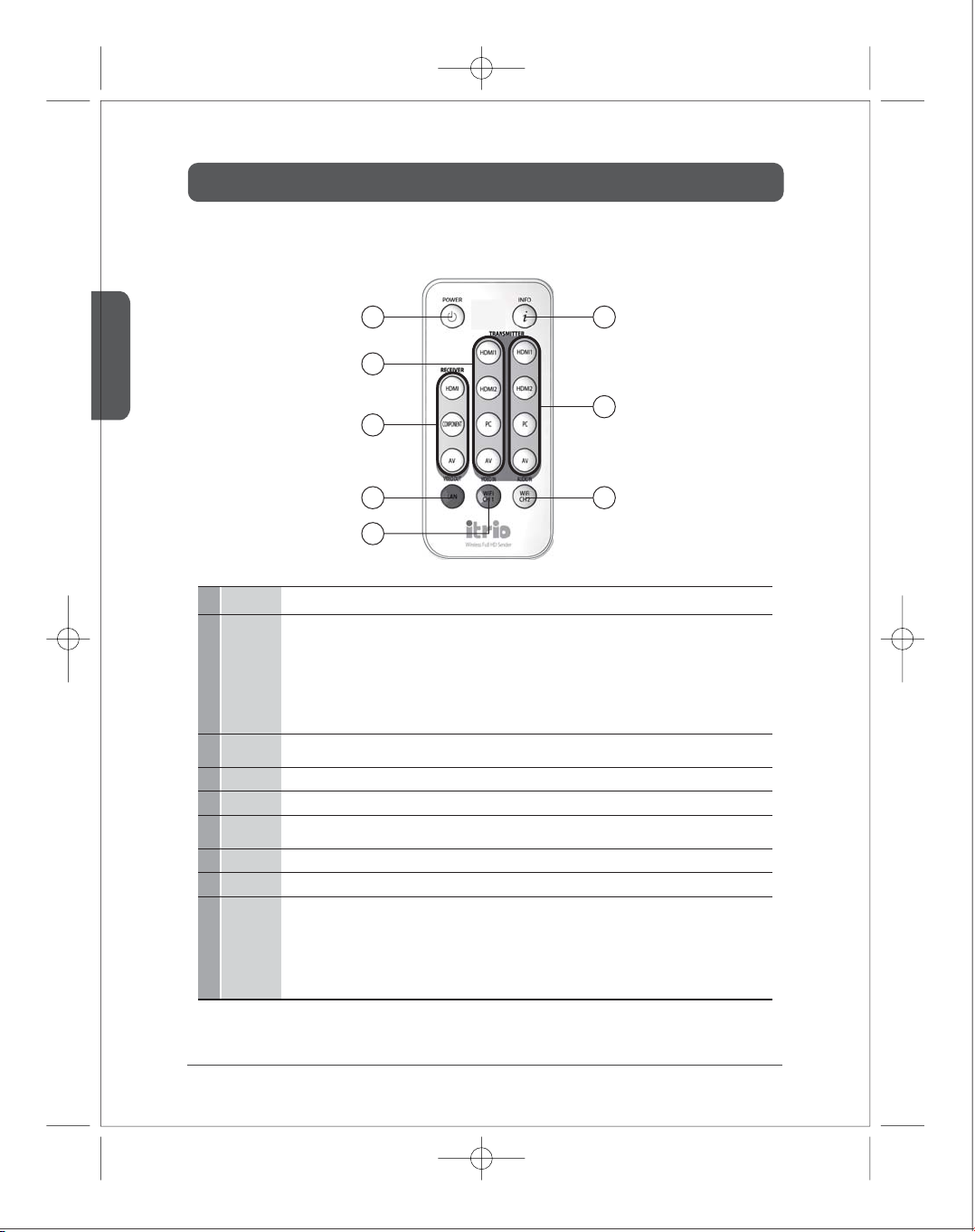
To turn on/o the power of transmitter and receiver.
○
Power on :
- If you turn on TX or RX when power/Link LED is on , both devices will be power-on simultaneously within 10 seconds.
POWER
1
INFO
2
VIDEO OUT
3
VIDEO IN
4
AUDIO IN
5
LAN(Red)
6
WiFi Ch1(Green)
7
WiFi Ch2(Yellow)
8
* TX : Transmitter, RX : Receiver
- You have to turn on each of TX and RX separately when power/Link LED is o, it may takes around 1 min 30 seconds for booting up.
○
Power o (press shortly) : When you turn o TX or RX, both devices will be power-o simultaneously and only power LED will be on.
○
Power o (press more than 4 sec) : When you turn o TX or RX, both devices will be power-o simultaneously, and LED will be o.
Power will be completely turned o.
Note1. If the power is o abnormally, the user's conguration may not be saved.
Display the current resolution, input / output ports, channel, WiFi reception (1/5~5/5). (5/5 strongest, 1/5 weakest)
It appears when you press and disappears automatically after around 20 seconds.
Select VIDEO output port of the receiver (HDMI, COMPO , AV)
Select VIDEO input port on the transmitter (HDMI1, HDMI2, PC, AV)
Select AUDIO input port on the transmitter (HDMI1, HDMI2, PC, AV)
Audio port is selected same with video port as a default. But you can select particular audio port using this button.
Select LAN (Cable) mode.
Select WiFi (Wireless) mode, Ch1.
Select WiFi (Wireless) mode, Ch2.
Note 1.
⑥~⑧
Note 2.
⑥~⑧
will be changed simultaneously.
Otherwise you should change on TX and RX separately. (Info screen appears on the display for 3 seconds if it changes appropriately.
Note 3.
It will be rebooting when you change for ⑥~⑧ . Power/Link LED will blink in a short time and reboot.
Note 4.
Link may be interfered caused by wrong setting or malfunction of ⑥~⑧ button. In this case, please select desired communication mode
(LAN/WiFi) or channel to each transmitter and receiver using remote control.
12
4
5
3
68
7
Function
are functioned HD-W100 model only.
are applied only when you press the button more than 5 seconds. On the normal link stage, if you change either TX or RX both device
10
Page 10
Installation
■
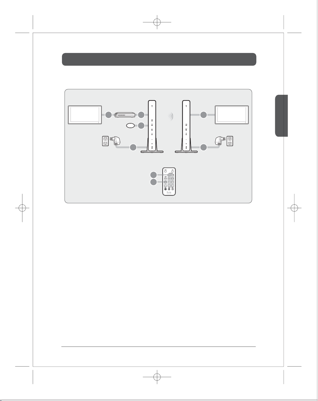
WiFi product
External Device
1 24
TV1 TV2
Adapter Adapter
IR Flasher
3
56
Transmitter Receiver
7
8
1)
Connect external devices to TV.
2)
Connect external devices to the transmitter through HDMI/COMPONENT/COMPOSITE port.
3)
Attach the IR Flasher in front of IR window of external devices.
4)
Connect the receiver to TV through HDMI/COMPONENT/COMPOSITE port.
5)
Connect the power adapter of the transmitter.
6)
Connect the power adapter of the receiver.
7)
It would takes around 1 min30sec to be turned on.
Select the input port of the transmitter using either remote controller or button on the front of the device after
the system is on.
English
8)
Select the output port of the receiver using either remote controller or button on the front of the device.
11
Page 11
Installation
■
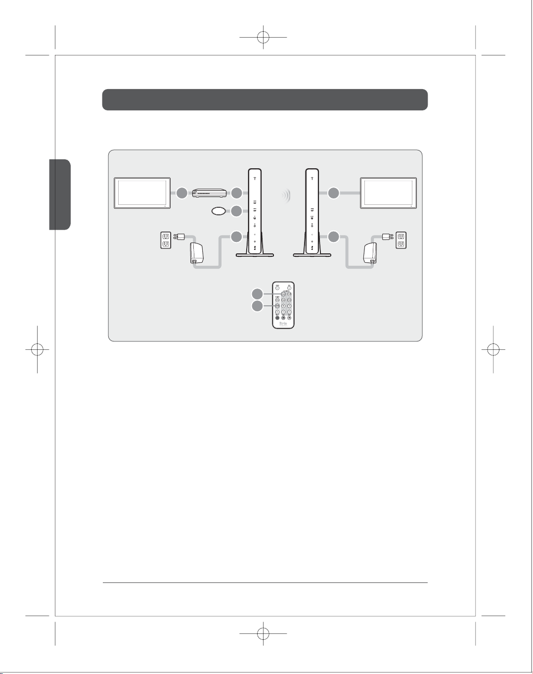
PLC product
English
External Device
12 4
TV1 TV2
PLC
IR Flasher
3
5
Transmitter Receiver
6
PLC
7
8
1)
Connect external devices to TV.
2)
Connect external devices to the transmitter through HDMI/COMPONENT/COMPOSITE port.
3)
Attach the IR Flasher in front of IR window of external devices.
4)
Connect the receiver to TV through HDMI/COMPONENT/COMPOSITE port.
5)
Connect the PLC adapter of the transmitter rst. Then, connect the power.
6)
Connect the PLC adapter of the receiver rst. Then, connect the power.
7)
It would takes around 1 min30sec to be turned on.
Select the input port of the transmitter using either remote controller or button on the front of the device after
the system is on.
12
8)
Select the output port of the receiver using either remote controller or button on the front of the device.
Page 12
Installation
■
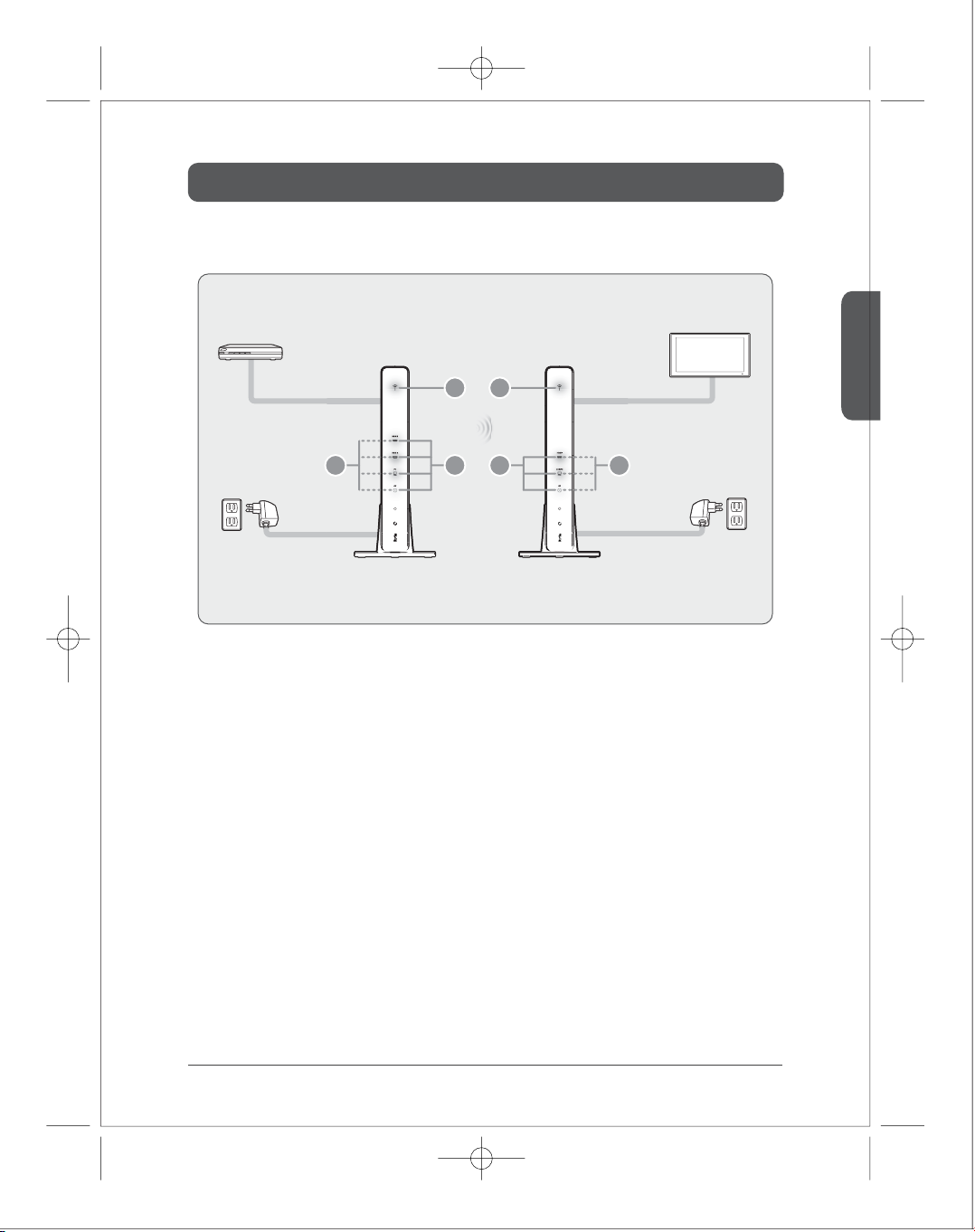
Trouble shoot
External Device
1
4
35
Adapter
Transmitter Receiver
1)
Transmitter power/ LED o -> Please check the power connection
2)
All LEDs of transmitter blink -> It would take around 1min 30sec for booting. Please unplug the power
adapter and connect again when it keeps blinking.
3)
Input source LED of transmitter blink -> When there is no input source signal or input unsupported signal.
It needs to connect input source cable or change video resolution.
4)
Power LED of receiver blinks -> When there is disconnection from the transmitter, because the distance
between transmitter and receiver is too far or malfunction of the PLC modem. Please locate transmitter and
receiver in near place and check the PLC operation.
5)
All LED of receiver blink -> It would take around 1min 30sec for booting. Please unplug the power adapter
and connect again when it keeps blinking.
2
6
Adapter
TV2
English
6)
Output source LED of receiver blink -> Because of the dierentiation between output resolution and
resolution of output monitor, output is only supported with low resolution. It needs to be connected with
high resolution monitor.
13
Page 13
English
Installation
■
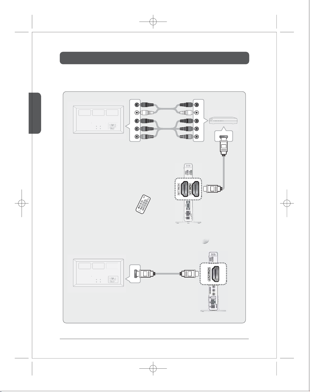
Device with HDMI : Connect through HDMI port
COMPONENT(YPbPr)Audio
External Device
TV1
(Use the the remote controller or the front button on devices)
TV2
COMPONENT(YPbPr) Audio
Select HDMI1 or HDMI2
HDMI
HDMI
Transmitter
14
Receiver
Page 14
Installation
■
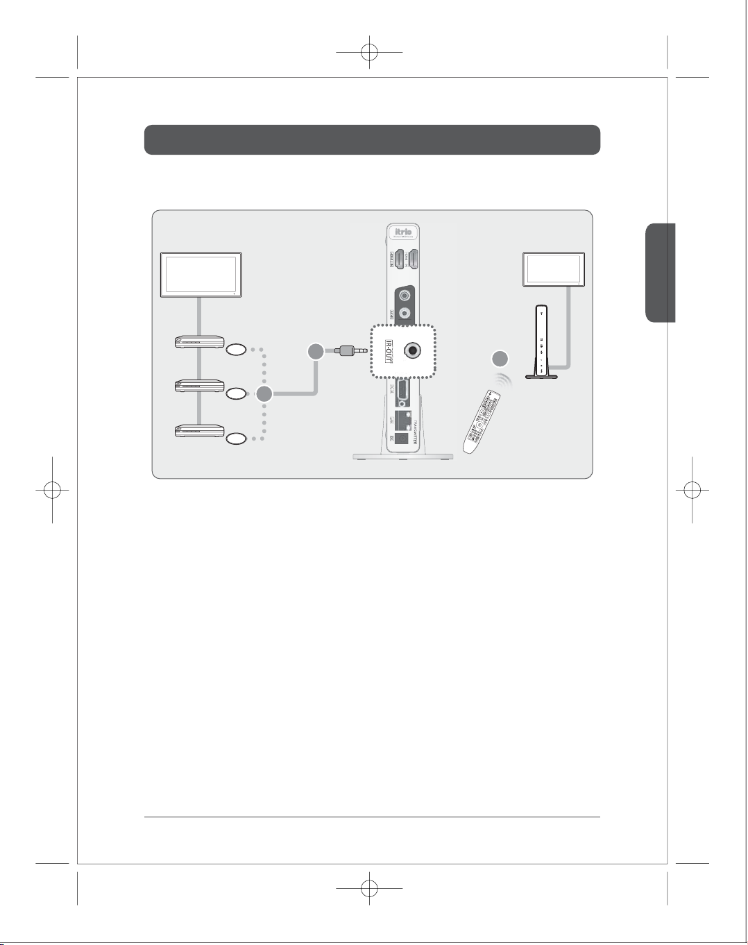
How to install IR-Flasher
English
TV1
External Device1
External Device2
External Device3
IR Flasher
IR Flasher
IR Flasher
2
You can connect up to
3 devices
1
Transmitter
3
Receiver
Use remote controller of
external device
TV2
From the receiver, you can remotely control the multimedia player which is connected to the transmitter.
Connect IR Flasher to IR-OUT of the transmitter.
1)
Place the end point of IR Flasher to near IR window of multimedia players.
2)
Control multimedia player remotely by pointing remote control of multimedia player to IR window
3)
of the receiver.
15
Page 15
Installation
■
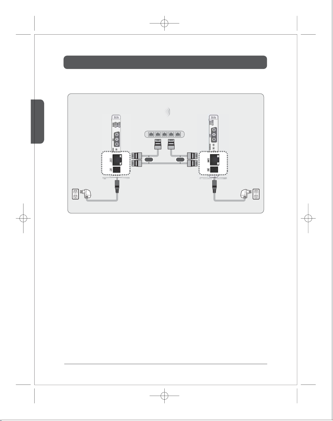
LAN model
English
Transmitter
LAN Hub
or or
LAN Cable
Adapter
Connect LAN cable directly between the transmitter and the receiver, or to the IP router/LAN hub.
1)
When you connect the transmitter and the receiver directly by UTP LAN cable, input the both end of
2)
Receiver
Adapter
LAN cable to the each LAN port of the product. Then, turn the power on.
When you connect to the IP router/L2 switching hub, please follow the process below.
3)
a.
Please check the IP address of the device.
b.
As a default conguration, transmitter’s IP address is 192.168.0.151, and receiver’s is 192.168.0.152.
The product has simple built-in web server inside. So, you can check and change the conguration. You can
connect the product to the PC via LAN cable and enter the IP address of the device on the web browser. At any
time, you can change the IP conguration as a default by factory set. (please refer to the Factory Reset on Page 16.)
16
When the default IP address of the transmitter/receiver are not used in your current network, just connect the
c.
LAN cable to the IP router or LAN hub and turn the power on.
When the default IP address of the transmitter/receiver are already being used, you have to set the available IP
d.
address to the transmitter and the receiver separately.
Connect the product to the PC via LAN cable, and enter new IP address of the transmitter/receiver respectively.
After setting new IP address, please follow the process.
For more information, please refer to the instruction at website (www.i-trio.com)
Page 16
Product Specication
■
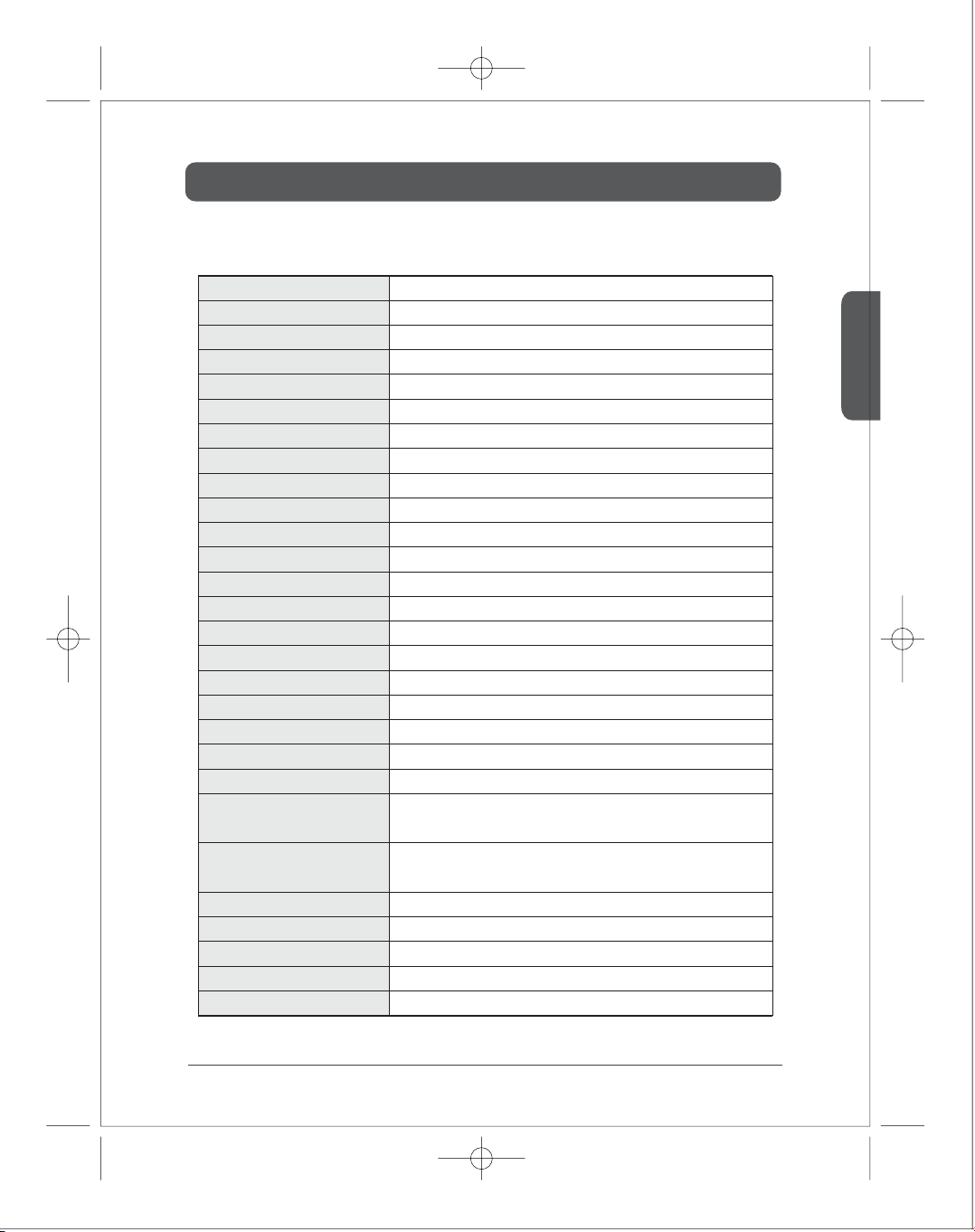
Specication
Video Compression
System Latency
Digital Video IN/OUT Interface
Analog Video Input Interface
Analog Video Output Interface
Input Video Ports
Output Video Ports
Video Resolutions (partial list)
Digital Audio IN/OUT Interface
Analog Audio IN/OUT Interface
Analog Audio Transmission
Input Audio Ports
Output Audio Ports
Radio Power
Modulation
Frequencies Supported
Bandwidth
Antenna
Security
WPS
Ethernet LAN
IR in Transmitter
H.264 Baseline Prole Level 4.2
Less than 30 ms delay between Transmitter and Receiver
HDMI-v1.3 compliant, Up to 24 bit RGB or YUV (4:2:2)
RGB Video with D-Sub, Component Video Input, Composite Video Broadcast Signals (CVBS)
YPbPr Component, Composite Video Broadcast Signals (CVBS)
2 x HDMI, 1 x RGB Analog with D-Sub, 1 x CVBS with COMPOSITE
1 x HDMI, 1 x YPbPr RCA, 1 x CVBS with COMPOSITE
480i/p, 720p, 1080i and 1080p (24fps/30fps/60fps)
2 Ch Linear PCM, DTS 5.1 Ch., AC3 5.1 Ch.
Mini stereo headphone jacks
48 kHz sampling with 16bits resolution
2 x HDMI, 1 x Mini Stereo Headphone jack
1 x HDMI, 1 x Mini Stereo Headphone jack x CVBS with COMPOSITE
63mW (+18dBm)
IEEE 802.11n: OFDM
5.15 ~ 5.25 GHz
40 MHz
2T x 2R, 2 internal antenna
802.1x, 802.11i, WPA2, WPA and WEP 64/128 TKIP AES
Wireless Protected Setup for easy set up and security conguration
10/100 BASE-TX
IR Receiver (front side) for itrio's IR Remote Controller
IR Flasher (rear side) for others' IR Remote Controller Blasting
English
IR in Receiver
Power Supply
Dimensions (mm)
Weight (g)
Color
Operating Temperature
IR Receiver (front side) for itrio's IR Remote Controller and
optional IR Extensive Receiver (rear side)
12V/2.0A DC (US/EU standards, CE/FCC/UL certied)
28(W) x 195(H) x 103(D)
Transmitter : 270g , Receiver : 270g
White/Black
Operating from 0°C ~ 40°C
17
Page 17
Product Specication
■
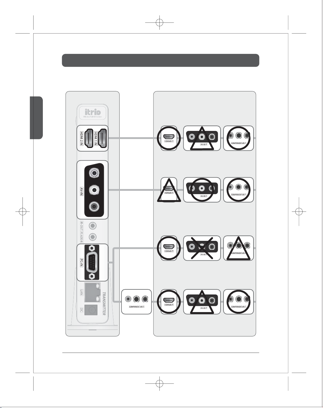
Supported port : How to make link between the transmitter and the receiver.
English
Transmitter
Receiver
HDMI1/HDMI2 input & Appropriate output port
* COMPOSITE(AV) output only supports 1080i/576i/480i input.
Composite(AV) input & Appropriate output port
* HDMI output is only available for the monitor supported 480i.
PC(D-Sub) input & Appropriate output port
* COMPONENT output only supports some of resolution.
Please refer to video format supported of this user's manual (page19).
18
Component
(Multimedia Device)
Component(D-Sub) input & Appropriate output port
* COMPOSITE(AV) output only supports 1080i/576i/480i input.
Page 18
Product Specication
■
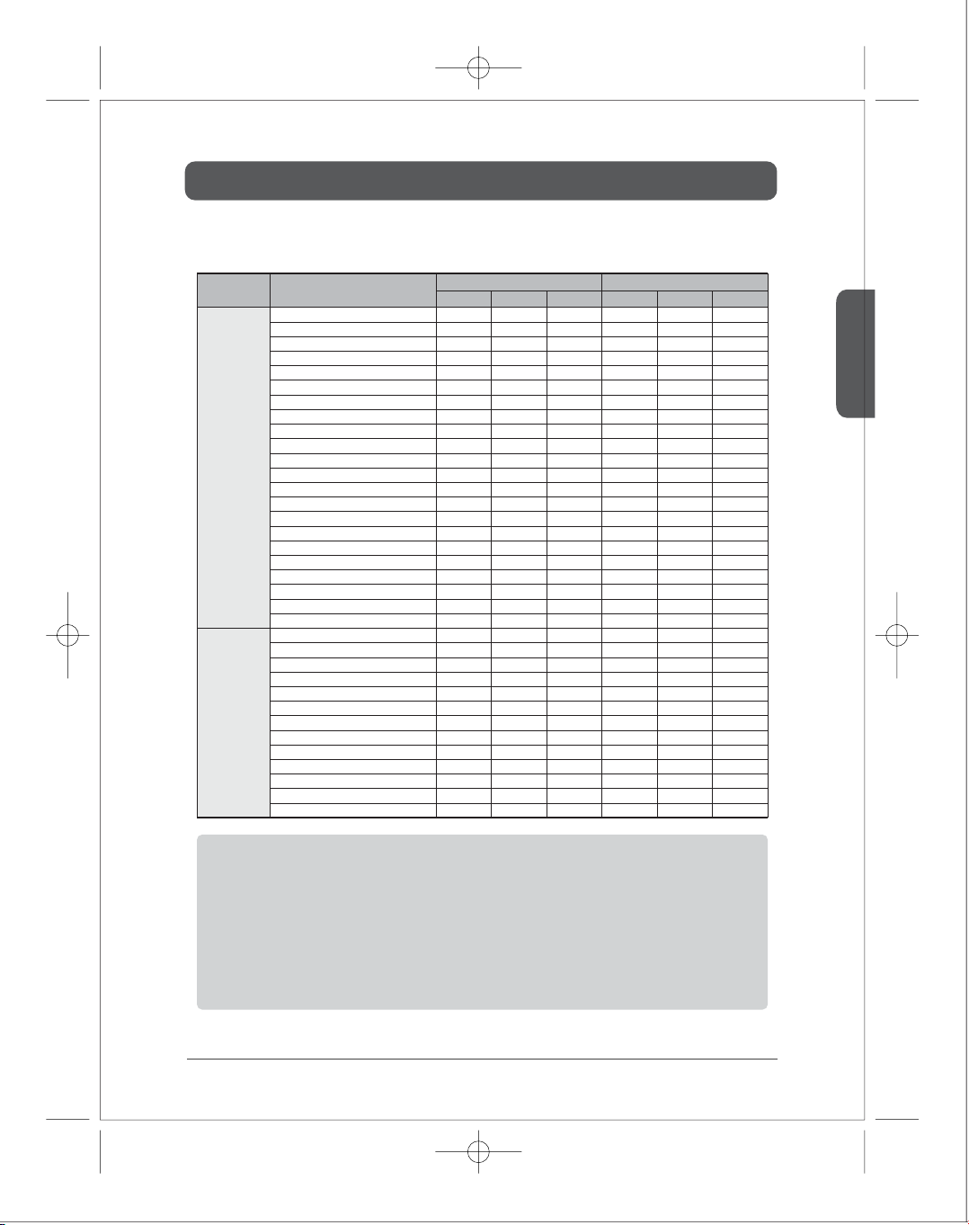
Video Format Supported
Video
Standard
VESA
Format
(PC standard)
DTV
Format
(TV standard)
Resolutions
640 x 480p60
640 x 480p70
640 x 480p85
800 x 600p60
800 x 600p70
800 x 600p85
1024 x 768p60
1024 x 768p70
1024 x 768p85
1152 x 864p60
1152 x 864p70
1152 x 864p85
1280 x 800p60
1280 x 960p60
1280 x 960p70
1280 x 960p85
1280 x 1024p60
1360 x 768p60
1440 x 900p60
1600 x 1200Rp60
1600 x 900p60
1680 x 1050p60
720 x 480I60(NTSC)
720 x 576I50(PAL)
720 x 480p60
720 x 576p50
1280 x 720p50
1280 x 720p60
1920 x 1080i50
1920 x 1080i60
1920 x 1080p24
1920 x 1080p25
1920 x 1080p30
1920 x 1080p50
1920 x 1080p60
1)
itrio Transmitter itrio Receiver
D-SUB HDMI COMP
HDMI
O
O
O
O
O
O
O
O
O
O
O
O
O
O
O
O
O
O
O
O
O
O
O
O
O
O
O
O
O
O
O
O
O
O
O
AV(CVBS) AV(CVBS)
O
O
O
O
O
O
O
O
O
O
O
O
O
O
O
O
O
O
X
O
X
O
O
O
O
O
O
O
O
O
O
X
X
O
O
X
O
X
O
X
O
X
O
X
O
X
O
X
O
X
O
X
O
X
O
X
O
X
O
X
O
X
O
X
O
X
O
X
O
X
O
X
O
X
O
X
O
X
O
O
X
O
X
X
O
X
O
X
O
X
O
X
O
X
O
X
O
X
O
X
O
X
O
X
O
X
X
X
X
X
X
△
X
X
△
X
X
X
△
X
X
△
X
X
△
X
X
O
O
O
O
O
O
O
O
X
X
X
X
X
X
X
X
X
X
X
X
X
X
X
X
X
X
X
X
X
X
X
X
X
X
X
O
O
X
X
X
X
O
O
X
X
X
X
X
English
Note 1.
1600 x 1200p60 reduced format
Note 2.
itrio just relays the input format of the video from the transmitter to the receiver. itrio does not change the
video format. If you want to change output format, you should change input format on the external device
which is connected to the transmitter.
Note 3.
HDMI output of the receiver doesn't support AV(NTSC:480i or PAL:576i) input signal from the transmitter.
Please use component output terminal of receiver.
Note 4.
Among HDMI input signal, only 1080i/480i/576i input video signal support AV output. Other HDMI input
signal doesn't support AV output of the transmitter. Please use HDMI or Component output terminal of the
transmitter.
Note 5.
PC that is connected with D-Sub of the transmitter support only HDMI output of the receiver.
19
Page 19
English
Product Specication
■
Audio Format Supported
1)
Digital Audio
-
Digital compressed audio : AC-3 Dolby Digital, DTS ( Pass Through)
2)
Analog audio
-
16bit 2-channel linear PCM (44.1kHz & 48kHz)
■
Change WiFi Frequency
If there are the devices that use same WiFi frequency, the receiver’s output video may be
1)
distorted because of frequency interference. In this case, you can change WiFi frequency in
order to avoid interference.
If you press the button (WiFi Ch1 / WiFi Ch2) of the remote control over 5 seconds, WiFi
2)
frequency will be changed and system will be rebooted.
If the transmitter and the receiver are linked appropriately, it is ne to change WiFi frequency
3)
on the one device. However, if the transmitter and the receiver are not linked, WiFi frequency
should be changed on each of transmitter and receiver respectively.
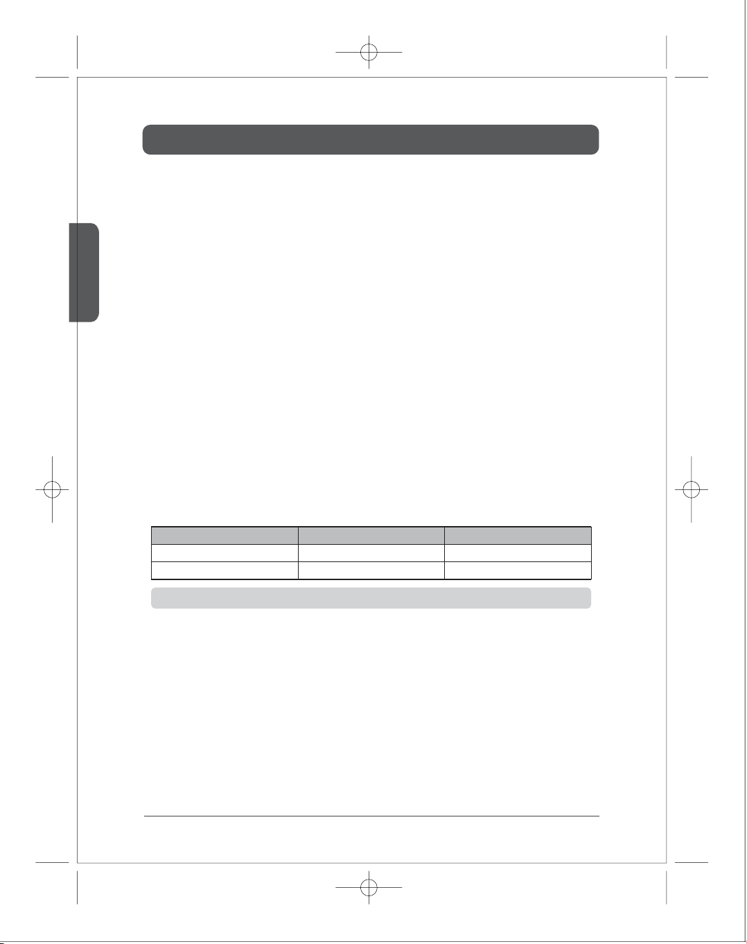
WiFi Channel Frequency Use Remote Control Button
Ch 1
Ch 2
5.19 GHz(WiFi Ch38)
5.23 GHz(WiFi Ch46)
WiFi Ch1 (Green)
WiFi Ch2 (Yellow)
■
1)
2)
20
This Function is applied to only wireless model(w).Note1.
Factory Reset
With pressing the power button of the transmitter or the receiver, connect the power.
Once you press the power button for 3 seconds, all the LED will blink and the system setting is set
to be factory mode.
Page 20
Product Specication
■
Software upgrade
1)
Download up-to-dated software (itrio.img) at web page (www.i-trio.com)
2)
Store this S/W in "root directory" of USB memory.
3)
Plug USB memory into the USB port of the receiver.
4)
With LEDs blinking, the receiver and the transmitter will be upgraded in sequence.
(It takes around 5 minutes)
When the refreshing is completed, the product will be rebooted.
5)
Important Notice)
a.
Update is available only when the transmitter and the receiver operate normally.
b.
NEVER remove the power during update.
(If the power is o during upgrading, the product will not work again.)
c.
During the update, screen does not display the video.
d.
When the product reboots again, you can remove the USB Memory.
English
21
Page 21
English
Q & A
■
Q & A
1)
Q :
A :
2)
Q :
A :
3)
Q :
A :
Power/Link LED keeps blinking and the transmitter and receiver are not linked
appropriately.
Communication method (LAN/WiFi) or channel may not be set appropriately. Please
set the desired communication method and channel by referring 4-5). ⑥~⑧.
Especially, when the system is wireless mode, make the transmitter and the receiver
closer, please check if the link is completed pressing Ch1 and ch2 for over 5 seconds
and, then, make them locate near TV. If link is established appropriately when they
are close but LED is blinking when they are apart, it means wireless signal is weakened
by some reason or it may be interfered by a wireless device which use the same
frequency in the near place.
When itrio is turned on rst time, TV screen doesn’t show clearly and after a while turn
into clear picture. Is it broken?
It is not a broken product. When the receiver receives the video data, there is noise on
screen if the receiver couldn’t receive the essential information. The screen will be
shown clearly soon.
Is it possible to use video output from HDMI splitter?
Yes, it is. However, low quality HDMI splitter may convey the video signal information
inappropriately or the electric feature of HDMI video signal form the HDMI splitter may
not satisfy the standard. Please use it carefully.
22
For the further information, please refer to our web page 'www.i-trio.com'
Page 22
www.AVL21c.com
 Loading...