

Page 1

MERGEPOINT® 53XX SP MANAGER
Installer/User Guide
Page 2

USA Notification
Warning: Changes or modifications to this unit not expressly approved by the party responsible for compliance could void the user’s authority to operate the equipment.
Note: This equipment has been tested and found to comply with the limits for a Class A digital device,
pursuant to Part 15 of the FCC Rules. These limits are designed to provide reasonable protection against
harmful interference when the equipment is operated in a commercial environment. This equipment generates, uses and can radiate radio frequency energy and, if not installed and used in accordance with the
instruction manual, may cause harmful interference to radio communications. Operation of this equipment
in a residential area is likely to cause harmful interference in which case the user will be required to correct the interference at his own expense.
Canadian Notification
This class A digital apparatus complies with Canadian ICES-003.
Cet appareil numérique de la classe A est conforme à la norme NMB-003 du Canada.
Safety and EMC Approvals and Markings for the MergePoint 5200 SP Manager
FCC Class B, EN 55022 Class B, EN 61000-3-2/-3-3, CISPR 22 Class B, EN 55024/CISPR 24,
(EN 61000-4-2, EN 61000-4-3, EN 61000-4-4, EN 61000-4-5, EN 61000-4-6, EN 61000-4-8, EN
61000-4-11), EN 60950/IEC 60950-Compliant, UL Listed (USA), CUL Listed (Canada), TUV Certified
(Germany), CE Marking (Europe)
Safety and EMC Approvals and Markings for the MergePoint 5224/5240 SPManager
FCC Class A; EN55022 Class A/CISPR 22 Class A; EN55024/CISPR 24 (EN61000-4-2,
EN61000-4-3, EN61000-4-4, EN61000-4-5, EN 61000-4-6, EN 61000-4-11); EN60950/IEC60950-
Compliant; CSA Listed (USA and Canada); CE Marking (Europe)
Page 3

MergePoint® Service
Processor Manager
SP5300/SP5324/SP5340
Inst al ler/ User Guide
Avocent, the Avocent logo, The Power of Being There, MergePoint and
DSView are registered trademarks of Avocent Corporation or its
affili ates in th e U. S. an d ot her cou ntr ie s. All ot he r mar ks are th e pr oper ty
of their respective owne rs.
© 2008 Avocent Corporation. 590-839-501D
Page 4
Instructions
This symbol is intended to alert the user to the presence of important operating and mainten ance (servicing)
instructions in the literature accompanying the appliance.
Dangerous Voltage
This symbol is intended to ale rt th e user to th e pre se nc e of uninsulated dangerous vo lta ge w ithin the product’ s
enclosure that may be of sufficient magnitude to constitute a risk of electric shock to persons.
Power On
This symbol indicates the principal on/off switch is in the on position.
Power Off
This symbol indicates the principal on/off switch is in the off position.
Protective Grounding Terminal
This symbol indicates a terminal which must be connected to earth ground prior t o making any other
connections to the equipment.
Page 5

TABLE OF CONTENTS
Table of Contents
List of Figures .................................................................................................................ix
List of Tables................................................................................................................... xi
Chapter 1: Product Overview....... ....... ...... ....... ...... ....... ...... ...... ....... ............................... 1
Features and Benefits ........................................................................................................................1
Supported Target Devices..................................................................................................................2
MergePoint SP5300 Appliance Configuration ..................................................................................3
LEDs on the MergePoint SP5300 appliance..............................................................................3
MergePoint SP5324/SP5340 Appliance Configuration ....................................................................4
Safety Precautions .............................................................................................................................5
Rack mount safety considerations ..............................................................................................6
Cabling installation, maintenance and sa fety tips......................................................................6
iii
Chapter 2: Installation and Setup................................................................................... 9
Configuring Power for the MergePoint SP manager ........................................................................9
Connecting to the Network ..............................................................................................................10
Configuring the MergePoint SP Manager Basic Settings ...............................................................11
Activating the MergePoint SP5300 Appliance License Keys ..........................................................12
Adding the MergePoint SP Manager to a DSView 3 Software Installation ....................................13
Configuring the MergePoint SP Manager Network Settings...........................................................13
Ethernet ports on the MergePoint SP5300 appliance..............................................................13
Ethernet ports on the MergePoint SP5324/SP5340 appliance.................................................14
Configuring MergePoint SP5300 appliance network settings.................................................15
Configuring MergePoint SP5324/SP5340 appliance network settings....................................16
Private Subnets on the MergePoint SP5324/SP5340 Appliance.....................................................17
Firewall/Packet Filtering ............................................................................ ...... ...... ..... ...................18
Chains.......................................................................................................................................18
Rules .........................................................................................................................................18
BMC Provisioning (IPMI Targets Only)......................................................................................... 19
Starting or stopping the BMC provisioning service (Admin users only).................................. 20
Configuring PXE parameters for IPMI BMC provisioning (Admin users only)......................20
BMC log..................................................................................... ...... ..... ....................................21
Page 6

iv MergePoint Service Processor Manager SP53XX Installer/User Guide
Users................................................................................................................................................21
Managing MergePoint SP manager user accounts..................................................................21
DHCP on the MergePoint SP Manager ..........................................................................................24
Discovering and Adding Target Devices (Admin us ers only)...................... ...... ...... ........................25
Discovering target devices .......................................................................................................25
Manually Adding a Single Target Device........................................................................................26
Managing Target Device Lists (Admin users only).........................................................................28
Managing Target Device Groups (Admin users only).....................................................................30
Managing SP Profiles (Admin users only) ......................................................................................31
Managing Default Users (Admin users only)..................................................................................33
Managing user accounts on target devices..............................................................................34
Configuring the MergePoint SP Manager Sys tem...........................................................................35
System settings (Admin users only)...........................................................................................35
PCMCIA for the MergePoint SP5324/SP5340 Appliance...............................................................37
Completing the MergePoint SP Manager Installation....................................................................37
Chapter 3: Operations ............................... ....... ...... ....... ...... ...... ....... ...... ....... ...... ....... ... 39
Using the MergePoint SP Manager.................................................................................................39
MergePoint SP manager web interface....................................................................................39
Power Management.........................................................................................................................41
Remote power and chassis management ..................................................................................41
Performing Target Device Group Operations.................................................................................42
Monitoring and Management..........................................................................................................44
Viewing sensor status ...............................................................................................................44
Viewing SEL events...................................................................................................................45
Viewing the accounting log ......................................................................................................45
Import/export data....................................................................................................................45
Accessing FRU information......................................................................................................46
Using the Alerts Viewer............................................................................................................46
Syslog........................................................................................................................................48
Configuring PET alerts ............................................................................................................49
Schedules .........................................................................................................................................50
Schedule a task (Admin users only)..........................................................................................50
Target Operations ............................................................................................................................51
Viewing target device information............................................................................................51
Page 7

Table of Contents v
Synchronizing blades for a blade chassis.................................................................................51
Changing the SoL port number ................................................................................................52
Changing the access account of a target device.......................................................................52
Changing target device parameters..........................................................................................52
Accessing system information................................................................................................... 53
Recovering provisioning...........................................................................................................54
Changing LAN parameters.......................................................................................................54
SNMP........................................................................................................................................54
Host table..................................................................................................................................57
Static routes....................................... ...... ...... ........................................................ ...... .............58
Using Serial over Lan (SOL)...........................................................................................................59
Device console and service processor console.........................................................................59
Configuring SoL parameters....................................................................................................61
NFS...........................................................................................................................................61
Remote Control................... ........................................................ ...... ...... .........................................62
Diagnostics ......................................................................................................................................62
Appliance Operations........................................... ..... ......................................................... .............63
MergePoint SP manager sessions ............................................................................................63
Upgrade.................................................................................................................................... 63
Boot configuration for the MergePoint SP5324/SP5340 appliance.........................................64
Unbinding the MergePoint SP manager from the DSView 3 server ........................................65
Chapter 4: Configuring External Authentication Services......................................... 67
Configuring a Kerberos authentication server.........................................................................68
Configuring an LDAP authentication server............................................................................69
Configuring an NIS authentication server................................................................................70
Configuring a RADIUS authentication server..........................................................................70
Configuring an SMB authentication server..............................................................................71
Configuring a TACACS+ authentication s erver ......................................................................71
Configuring an authentication method for the MergePoint SP manager.................................72
Chapter 5: Accessing Target Devices Using DirectCommand or Native IP ............. 73
DirectCommand...............................................................................................................................75
Native IP ..........................................................................................................................................77
Native IP operations using the web interface...........................................................................78
Native IP operations using SSH Commands............................................................................80
Page 8

vi MergePoint Service Processor Manager SP53XX Installer/User Guide
Chapter 6: Administration Tasks Not Performed in the Web Interface..................... 83
Using MindTerm to Create an SSH Tunnel.....................................................................................83
Using SSH with the MergePoint SP Manager.................................................................................84
The SSH command line format.................................................................................................84
User shell..................................................................................................................................85
MgpShell...................................................................................................................................86
SSH Passthrough .............................................................................................................................86
SSH Passthrough commands.................................................................................................... 86
Telnet ........................................................................................................................................88
Configuring the Users’ Console Login Menu..................................................................................88
Configuring Routes With CLI..........................................................................................................90
Backing Up Configuration Files......................................................................................................91
Restoring backed up configuration files...................................................................................91
Restoring factory default configuration files............................................................................91
Configuring Groups for Use with Authentication Servers...............................................................91
Configuring group authorization for LDAP authentication.....................................................92
Configuring group authorizations on an AD server.................................................................92
Defining groups on an LDAP server running OpenLDAP.......................................................93
Configuring group authorization f or RADIUS authentication................................................. 95
Configuring group authorization for TACACS+ authentication..............................................97
Switching the Port Speed in the MergePoint SP5324/SP5340 Appliance....................................... 99
Chapter 7: Using the CLI Utility .................................................................................. 101
CLI Utility Overview......................................................................................................................101
Execution Modes............................................................................................................................101
Command line mode...............................................................................................................101
Interactive mode ................................................. ...... ...... ........................................................ 102
Batch mode .............................................................................................................................102
CLI Options....................................................................................................................................102
CLI Parameters and Arguments....................................................................................................103
Entering a command in interactive mode...............................................................................103
Entering a command in command code..................................................................................104
Entering a command in batch mode.......................................................................................104
Autocompletion..............................................................................................................................105
CLI Commands..............................................................................................................................106
Page 9

Table of Contents vii
add ..........................................................................................................................................106
cd.............................................................................................................................................110
commit ....................................................................................................................................111
delete.......................................................................................................................................111
get | show ........................................................................................ ..... ...... ............................112
list ...........................................................................................................................................113
quit | exit ....................................................... ..... ....................................................................113
quit! ........................................................................................................................................114
rename ...................................................................................................................................114
revert.......................................................................................................................................114
set............................................................................................................................................115
shell ........................................................................................................................................115
version.....................................................................................................................................116
Summary of How to Configure the Top Level Parameters............................................................116
Chapter 8: Using SMASH Command Line Management .......................................... 125
SMASH CLP Overview..................................................................................................................126
SMASH CLP implementation .................................................................................................126
Supported profiles...................................................................................................................127
Terms ......................................................................................................................................128
General command syntax .......................................................................................................129
Targets....................................................................................................................................130
Using Commands...........................................................................................................................131
Viewing targets, properties and commands for a target ........................................................131
Setting properties on a target.................................................................................................131
Associations............................................................................................................................132
Managing MergePoint SP manager.......................................................................................132
Managing servers...................................................................................................................139
Chapter 9: Using WS-Management ............................................................................ 147
WS-MAN Commands for the MergePoint SP Manager.................................................................147
Automatic discovery service command...................................................................................147
Automatic discovery command...............................................................................................149
AvctMP_DiscoveryServiceAccessBySAP Associations commands........................................150
Power management service command....................................................................................150
Power management command................................................................................................151
Page 10

viii MergePoint Service Processor Manager SP53XX Installer/User Guide
Power management service association command ................................................................152
SSH service and Telnet service commands.............................................................................152
Examples........................................................................................................................................155
Viewing the instances of the class AvctMP_DiscoverySAP ...................................................155
Appendices................................................................................................................... 163
Appendix A: Troubleshooting........................................................................................................163
Service processor troubleshooting.................................................................................................164
Appendix B: Technical Specifications...........................................................................................165
Appendix C: Access Privileges......................................................................................................167
Appendix D: Configuring the BIOS Settings for SoL ....................................................................170
Appendix E: Configuring a Virtual Serial Por t.............................................................................171
Appendix F: Profile Configuration................................................................................................172
Appendix G: Glossary and Acronyms............................................................................................182
Appendix H: Technical Support.....................................................................................................184
License Information..................................................................................................... 185
Page 11

LIST OF FIGURES
List of Figures
Figure 1.1: MergePoint SP5300 Appliance Configuration...............................................................3
Figure 1.2: MergePoint SP5324/SP5340 Appliance Configuration ................. ................................4
Figure 2.1: DC Power Connection Terminal Block........................................................................10
Figure 3.1: MergePoint SP Manager Web Interface ......................................................................40
Figure 5.1: MergePoint SP5324/SP5340 SP Manager Native IP Configuration...........................74
Figure 6.1: MindTerm Basic Tunnels Setup Dialog Box.................................................................84
ix
Page 12

x MergePoint Service Processor Manager SP53XX Installer/User Guide
Page 13

LIST OF TABLES
List of Tables
Table 1.1: Descriptions for MergePoint SP5300 Appl iance Configuration .....................................3
Table 1.2: Descriptions for MergePoint SP5324/SP53 40 Applian ce Configu ratio n........................4
Table 2.1: DC Power Connection Details.......................................................................................10
Table 2.2: Reserved Words..............................................................................................................22
Table 2.3: Target Device Types Displayed in the Managed/Unmanaged Targets Lists .................28
Table 2.4: Default Service Processor Usernames and Passwords..................................................33
Table 3.1: MergePoint SP Manager Web Interface Descriptions................................................... 40
Table 4.1: Supported Authentication Methods ................................................................................ 67
Table 5.1: Descriptions for MergePoint SP5324/SP5340 SP Manager Native IP Configuration..74
Table 6.1: Supported Service Processor Commands.......................................................................87
xi
Table 7.1: CLI Utility Options.......................................................................................................102
Table 7.2: Parameters that Work with the CLI add Command.....................................................108
Table 7.3: Setting Top Level CLI Parameters...............................................................................116
Table 8.1: Actions Supported for Each Server Type .....................................................................126
Table 8.2: Terms Used in Commands............................................................................................129
Table 8.3: Map of Targets and Descriptions.................................................................................130
Table B.1: MergePoint SP5300 Appliance Technical Specifications............................................165
Table B.2: MergePoint SP5324/SP5340 Appliance Specifications...............................................166
Table F.1: Default Family Names and Corresponding Expect Script Names...............................173
Table F.2: Expect Script Exit Codes..............................................................................................174
Table F.3: Default Command Templates.......................................................................................177
Page 14

xii MergePoint Service Processor Manager SP53XX Installer/User Guide
Page 15

CHAPTER
1
The MergePoint service processor (SP) manager is a secure, centralized enterprise management
solution for target devices equipped with IPMI, HP
service processors. You can remotely perform server management tasks, including power control
and console access, on managed target devices.
The MergePoint SP manager provides a standardized interface independent of the management
protocols used to manage each target device. Management operations can be performed using the
following three methods:
Product Over view
®
1
, Dell®, IBM®, Sun® and Fujitsu-Siemens
•The DSView® 3 management software interface.
• The MergePoint SP manager web interface from a standard web browser.
• Commands or scripts over a Telnet, command line interface (CLI) utility, Systems
Management Architec ture for Se rver Hardwa re Command Line Protocol (SMASH CLP) or
Secure Shell (SSH) session.
SMASH CLP is a standards-based user and scripting interface defined by the Distributed
Management Task Force (DMTF). This interface provides a single command line interface to
manage servers from multiple manufacturers, simplifying management and streamli ning
interoperability while providing scripting and automation capabilities.
NOTE: MergePoint SP manager refers to the SP5300/SP5324/SP5340 models. For features supported only by
specific models, the supported model is noted.
Features and Benefits
The MergePoint SP53XX appliance provides secure Serial ov er LAN (SoL) con so le access, po wer
control and server hardware monitoring. With easy-to-use IPMI provisioning capabilities and an
auto discovery mechanism for server management technologies within the network, the
MergePoint appliance is ideal for enterprise data cen ters as well as for hi gh performan ce computing
(HPC) and other clustering
The MergePoint appliance allows enterprise-class authentication, authorization and auditing
(AAA) security and encryption, and extends this functionality to all servers. Other standard
features include data logging, event detection and notification, SNMP proxy, graphing and alarm
environments.
Page 16

2 MergePoint Service Processor Manager SP53XX Installer/User Guide
events for sensors and shared access to management ports. Also, simultaneous power control of
multiple servers boosts the already existing power management capabilities of service processors,
including graceful shutdown support for IPMI.
With multiple Ethernet ports, the MergePoint SP5324/SP534 0 appli a nces connect point-to-point
with Ethernet-based service processors. By isolating and protecting the connected service
processors from the external production network, the MergePoint SP5324/SP5340 appliances
provide secure and efficient rack- level management with seamless integration into the management
infrastructure.
Supported Target Devices
The MergePoint SP ma nager su pports target d evices with a variety of ser vice processors, includ ing:
• IPMI (Intelligent Platform Management Interface) 1.5 and 2.0
NOTE: The IPMI service processor is also referred to as a baseboard management controller (BMC).
• Dell DRAC (Dell Remote Access Card) 3, 4 and 5
• Dell 10G
• Dell DRAC/MC (Remote Access Controller/Modular Chassis)
• Hewlett Packard (HP) iLO (Integrated Lights-Out) and iLO 2
•HP IPMI
• HP BladeSystem c-Class
• IBM BladeCenter E Chassis
• IBM BladeCenter H Chassis
• IBM RSA (Remote Supervisor Adapter) II
• Sun ILOM (Integrated Lights Out Management)
• Sun ALOM (Advanced Lights Out Management)
• FSC iRMC (Fujitsu-Siemens Corp integr ated R emote Management Card)
Additionally, administrators can configure new target devices or modify existing target device
types for service processors not included in the previous list. For a complete list of supported
service processors, see the MergePoint SP manager release notes.
Page 17
MergePoint SP5300 Appliance Configuration
1
2
3
4
5
6
7
8
9
Chapter 1: Product Overview 3
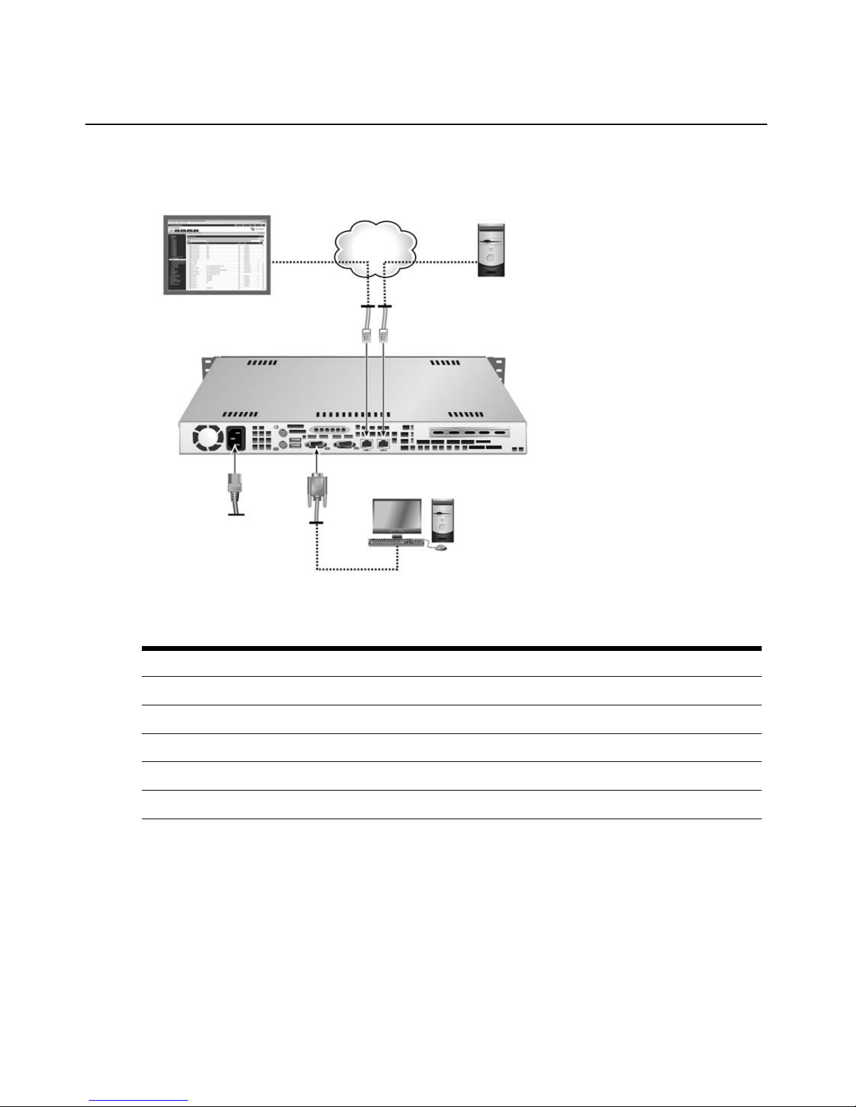
Figure 1.1: MergePoint SP5300 Appliance Configuration
Tab le 1.1: Descriptions for MergePoint SP5300 Appliance Configuration
Number Description Number
1 Remote User Web Interface 6 RJ-45 Ethernet Ports
2 LAN 7 Power
3 Target Device 8 Connection to the Serial Port
4 CAT 5 Cables 9 Terminal or Workstation (for Configuration)
5 MergePoint SP5300 Appliance
LEDs on the MergePoint SP5300 appliance
On the front of the MergePoint SP5300 appliance, the LAN LED provides information about the
LAN activity; the LED blinks to indicate activity. The power LED is green if the MergePoint
SP5300 appliance is turned on.
Page 18

4 MergePoint Service Processor Manager SP53XX Installer/User Guide
MergePoint SP53XX Appliance (SP5340 Shown)
6
8
7
LAN
MergePoint SP5324/SP5340 Appliance Configuration
1
Figure 1.2: MergePoint SP5324/SP5340 Appliance Configuration
Table 1.2: Descriptions for MergePo int SP53 24/SP5340 Appliance Configuration
2
3
4
5
Number Description Number Description
1 Private ethernet ports (24 or 40) 5 10/100 secondary public Ethernet port -
2 10/100/GE (Gigabit Ethernet) primary
public Ethernet
3 Auxiliary (AUX) port (disabled) 7 Remote user web interface
4 Console port - For connecting either a
terminal or a computer running a terminal
emulation program
port
(Optional) For connection to a second
network connection or for failover
connection to the primary
6 Blade or service processor
8 Console user
network
Page 19

Safety Precautions
To avoid potentially fatal shock hazard and possible damage to equipment, please observe the
following precautions:
• Do not use a 2-wire power cord in any Avocent product configuration.
• Test AC outlets at the target device and monitor for proper polarity and grounding.
• Use only with grounded outlets.
NOTE: The AC inlet is the main power disconnect.
Failure to observe the precautions in this section may result in personal injury or damage
to
equipment.
Observe the following general safety precautions when setting up and using Avocent equipment.
• Follow all cautions and instructions marked on the equipment.
• Follow all cautions and instructions in the installatio n documentation or on any cautionary
cards shipped with the product.
• Do not push objects through the openings in the equipment. Dangerous voltages may be
present. Objects with conductive properties can cause fire, electric shock or damage to
the
equipment.
• Do not make mechanical or electrical modificat ions to the equipment.
• Do not block or cover openings on the equipment.
• Choose a location that avoids excessive heat, direct sunlight, dust or chemical exposure, all of
which can cause the product to fail. For example, do not place an Avocent product near a
radiator or heat register, which can cause overheating.
• Connect products that have dual power supplies to two separate power sources, for example,
one commercial circuit and one uninterruptible power supply (UPS). The power sources must
be independent of each other and must be controlled by separate circuit breakers.
• For products that have AC power sup pli es, ensu re th at the vol tage a nd freq uency of the power
source match the voltage and frequency on the label on the equipment.
• Products with AC power supplies have grounding-type three-wire power cords. Make sure the
power cords are plugged into single
• Do not use household extension po wer cords with Avocent equipment because household
extension cords are not designed for use with computer systems and do not have
overload
• Make sure to connect DC power supplies to a grounded return.
• Ensure that air flow is sufficient to prevent extreme operating temperatures. Provide a
minimum space of 6 inches (15 cm) in front and back for adequate airflow.
• Keep power and interface cables clea r of foot traf fic. Route cables inside walls, under the f loor ,
through the ceiling or in protective channels or raceways.
protection.
Chapter 1: Product Overview 5
-phase power systems that have a neutral ground.
Page 20

6 MergePoint Service Processor Manager SP53XX Installer/User Guide
• Route interface cables away from motors and other sources of magnetic or radio
frequency
interference.
• Stay within specified cable length limitations.
• Leave enough space in front and back of the equipment to allow access for servicing.
When installing Avocent equipment in a rack or cabinet, observe the following precautions:
• Ensure that the floor’s surface is level.
• Load equipment starting at the bottom first and fill the rack or cabinet from the bottom to
the
top.
• Exercise caution to ensure that the rack or cabinet does not tip during installation and use an
anti
-tilt bar.
When using a desk or table, observe the following precautions:
• Choose a desk or table sturdy enough to hold the equipment.
• Place the equipment so that at least 50% of the equipment is inside the table or desk’s leg
support area to avoid tipping of the table or desk.
Rack mount safety considerations
• Elevated Ambient Temperature: If installed in a closed rack assembly, the operating
temperature of the rack environment may be greater than room ambient. Use care no t to exceed
the rated maximum ambient temperature of the switch.
• Reduced Air Flow: Installation of the equipment in a rack should be such that the amount of
airflow required for safe operation of the equipment is not compromised.
• Mechanical Loading: Mounting of the equipment in the rack should be such that a hazardous
condition is not achieved due to uneven mechanical loading.
• Circuit Overloading: Consideration should be given to the connection of the equipmen t to the
supply circuit and the effect that overloading of circuits might have on overcurrent protection
and supply wiring. Consider equipment nameplate ratings for maximum current.
• Reliable Earthing: Reliable earthing of rack mounted equipment should be maintained. Pay
particular attention to supply connections other than direct connections to the branch circuit
(for example, use of power strips).
Cabling installation, maintenance and safety tips
The following is a list of important safety considerations that should be reviewed prior to installing
or maintaining your cables:
• Keep all CAT 5 runs to a maximum of 10 meters each.
• Maintain the twists of the pairs all the way to the point of termination, or no more than one half
inch untwisted. Do not skin off more than one inch of jacket while terminating.
• If bending the cable is necessary, make it gradual with no bend sharper than a one inch radius.
Allowing the cable to be sharply bent or kinked can permanently damage the cable’s interior.
Page 21

Chapter 1: Product Overview 7
• Dress the cables neatly with cable ties, using low to moderate pressure. Do not overtighten ties.
• Cross-connect cables where necessary, using rated punch blocks, patch panels and
components. Do not splice or bridge cable at any point.
• Keep CAT 5 cable as far away as possible from potential sources of EMI, such as electrical
cables, transformers and light fixtures. Do not tie cables to electrical conduits or lay cables on
electrical fixtures.
• Always test every installed segment with a cable tester. “Toning” alone is not an
acceptable
test.
• Always install jacks so as to prevent dust and other contaminants from settling on the contacts.
The contacts of the jack should face up on the flush mounted plates, or left/right/down on
surface mount boxes.
• Always leave extra slack on the cables, neatly coiled in the ceiling or nearest concealed
location. Leave at least five feet at the work outlet side and 10 feet at the patch panel side.
• Choose either 568 A or 568B w iring standard befor e beg inning . Wire all jacks and patch panels
for the same wiring scheme. Don’t mix 568A and 568B wiring in the same installation.
• Always obey all local and national fire and building codes. Be sure to firestop all cables that
penetrate a firewall. Use plenum rated cable where it is required.
CAUTION: This MergePoint SP manager contains an internal battery that is used for the real time clock. This
battery is not a field replaceable item, and replacement should not be attem pt ed by a user. If real time clock
errors occur and the battery is suspected, visit http://www.avocent.com/support or contact the Avocent Technical
Support location nearest you.
WARNING: For Service Personnel Only - There is a risk of explosion if the battery is replaced with an incorrect
type. Dispose of used batteries according to the manufacturer’s instructions.
Page 22

8 MergePoint Service Processor Manager SP53XX Installer/User Guide
Page 23

CHAPTER
Installation and Setup
2
Configuring Power for the MergePoint SP manager
The MergePoint SP manager is supplied with single or dual AC or DC power supplies.
To configure AC power:
1. Make sure that the power switch on the MergePoint SP manager is turned off.
2. Plug the power cable into the MergePoint SP manager and in to a power source.
3. Turn on the MergePoint SP manager.
9
To configure DC power:
DC power is connected to DC-powered MergePoint S P manager s by way of three wires: Return
(RTN), Ground (GND) and -48VDC.
WARNING: It is critical that the power source supports the DC power requirements of your appliance. Make sure
that your power source is the correct type and that your DC power cables are in good condition before
proceeding. Failure to do so could result in damage to the equipment or in personal injury .
The following diagram shows the connector configuratio n for connecting DC power. You may use
either a flat-blade or Phillips screwdriver for this procedure.
Page 24

10 MergePoint Service Processor Manager SP53XX Installer/User Guide
1 2 3 4
Figure 2.1: DC Power Connection Terminal Block
Table 2.1: DC Power Connection Details
Number Description
1 Power switch
2 RTN (Return)
3 GND (Ground)
4 -48VDC
1. Make sure that the power switch on the console server is turned off.
2. Make sure that DC power cables are not connected to a power source.
3. Remove the protective cover from the DC power block by sliding it to the l eft or right.
4. Loosen all three DC power connection terminal screws.
5. Connect your return lead to the RTN terminal and tighten the screw.
6. Connect your ground lead to the GND terminal and tighten the screw.
7. Connect your -48VDC lead to the -48VDC terminal and tighten the screw.
8. Slide the protective cover back into place over the DC terminal block.
9. If your MergePoint SP manager has dual-input DC terminals, repeat steps 3 - 8 for the second
terminal.
10. Connect the DC power cables to the DC power source and turn on the DC power source.
11. Turn on the Me rgePoint SP manager.
Connecting to the Network
To connect the MergePoint SP manager and service processors to the network:
1. Rack mount or place the MergePoint SP manager at the top of your server rack.
Page 25

Chapter 2: Installation and Setup 11
2. For a MergePoint SP5300 appl iance: Using Eth ernet cables, co nnect the LAN1 (eth0) network
port on the back of the appliance to the external network, and connect the LAN2 (eth1) port to
the internal network. In a typical installation, the LAN1 port provides access to the web
interface, and the LAN2 port provides access to the service processors.
-or-
For a MergePoint SP5324/SP5340 appliance: Connect an Ethernet cable from the primary
Ethernet 10/100/GE (Gigabit Ethernet) port to the network. If desired, connect an Ethernet
cable to the secondary Ethernet 10/100 port and configure the port for failover (see
Configuring MergePoint SP5324/SP5340 appliance network settings on page 16).
Connect an Ethernet cable from any private Ethernet port on the MergePoint SP5324/SP5340
appliance to dedicated Ethernet ports on a service processor or a dedicated Ethernet port on a
blade server that manages multiple blade service processors.
3. Turn on the power switches of the connected devices.
NOTE: Service processors should be configured according to their manufacturer’s instructions.
Configuring the MergePoint SP Manager Basic Settings
Before a MergePoint appliance can be added to you r network, it must have an IP address to identify
it. By default, it is DHCP enabled and can obtain an IP address from an available DHCP server.
For installations where a DHCP server is unavailable or not desired, the IP ad dress can be assigned
through a serial connection.
To configure the MergePoint SP manager IP address through a serial connection:
1. Connect a terminal or a workstation that is running a terminal emulation program to the
serial
port.
2. Start a session with the port settings of serial speed as 9600 bps, data length as 8 data bits,
parity as none, stop bits as 1, flow control as none and emulation as ANSI.
Once a connection is established, a prompt appears.
3. For the MergePoint SP5300 appliance:
a. Type 2 (Network Config).
b. Type 1 (Setup eth) to configure any of the listed network settings specific to your network.
-or-
For a MergePoint SP5324/SP5340 appliance:
a. Log into the console port as root with the default password avocent.
b. Enter the passwd command, and enter and confirm a new password for the root user.
c. Type cli to load the CLI utility.
Page 26

12 MergePoint Service Processor Manager SP53XX Installer/User Guide
d. Configure the primary Ethernet interface (eth0) by setting the method to static and
assigning a static IP address, a gateway and a netmask:
cli> set network interface eth0 method static address
<SPmanager_IPaddress> gateway <gateway_IP_address> netmask
<netmask>
e. Specify a hostname, a domain, a DNS server IP addres s, and an optional secondary DNS
server IP address:
cli> set network hostname <appliance_name> resolv domain
<domain_name> dns0 <DNS_server_IPaddress> dns1
<secondary_DNS_server_IPaddress>
f. Confirm the configuration for the interface:
cli> get network interface eth0
g. Confirm the name server configuration:
cli> get network resolv
h. Save the changes:
cli> commit
i. Exit from the CLI utility:
cli> quit
NOTE: To restore default configuration parameters, type restorefactory. To restart the MergePoint SP manager
using a previous firmware version, type roll_back.sh.
NOTE: For more information on configuring IP address, see Summary of How to Configure the Top Level
Parameters on page 116.
Activating the MergePoint SP5300 Appliance License Keys
You must register your MergePoint SP5300 appliance online at www.avocent.com to obtain a
master license key. The master key must be configured before you can discover and manage any
target devices. The license included with your MergePoint SP5300 appliance allows you to
discover and manage up to 64 target devices.
NOTE: Registration is not required for the MergePoint SP5324/SP5340 appliance.
A license key is made up of a master key and a slave key(s). The mast er key is used to activate the
MergePoint SP5300 appliance and i ts slave keys speci fy the number of managed target devices that
are supported by the
You may purchase upgrade licens es to add support for additional target devices up to a maximum
of 256. If you purchase one or more upgrade licenses, perform the following procedures to
license.
Page 27

Chapter 2: Installation and Setup 13
configure the MergePoint SP5300 appliance with the master key and slave key(s) for the new
license key(s).
To activate the MergePoint SP5300 appliance license:
1. Follow the instructions on the registration card included with the MergePoint SP5300
appliance to activate the appliance serial number. Once completed, you will receive a master
license key.
2. Open a web browser and enter the IP address (http://<appliance IP address>) of
appliance.
the
3. The MergePoint SP5300 appliance web interface window appears. Type the master key in the
fields provided and click Add.
4. The User Login window appears. Type admin as the username and type admin as the
password. To change the admin password, see
on page 22.
To view license information (Admin users only):
5. Click System – Licenses for a license summary and list of license keys and descriptions.
To add a master or slave key:
To add an appliance user (Admin users only):
1. Clic k t he System tab.
2. In the top navigation bar, click Licenses. The License window appears.
3. Click Add Master Key or Add Slave Key and type the master key.
4. Click Apply.
Adding the MergePoint SP Manager to a DSView 3
Software
Installation
If you will be u sin g t h e Merg ePo i nt S P man ager w ith in a D SView 3 software installation, you may
now use the DSView 3 software Add Appliance wizard to add the MergePoint SP manager and
finish configuration. For detailed instructions, refer to the DSView 3 software installer/user guide.
Configuring the MergePoint SP Manager Network Settings
Ethernet ports on the MergePoint SP5300 appliance
The MergePoint SP5300 appliance has two public Ethern et po rts (eth0 and eth1) , which ar e label ed
LAN1 and LAN2. The eth0 port is
connecting to service processors on the internal network.
NOTE: Connecting service processors to eth0 is not recommended because some services, like BMC
provisioning or DHCP servers, only listen to eth1.
for connecting to the external network and eth1 is for
Page 28

14 MergePoint Service Processor Manager SP53XX Installer/User Guide
Ethernet ports on the MergePoint SP5324/SP5340 appliance
The MergePoint SP5324/SP5340 ap plia nce has two pub lic Ethernet por ts (eth0 and eth1 ) and 24 or
40 Ethernet private ports. The public ports are used for connecting to the public (or management)
network and the private ports are used for connecting to service processors on the private network.
Therefore, the managed private side of th e MergePoi nt SP manager is isolated from the public side
to ensure security. Access to all connected service processor servers is consolidated through the one
publicly known IP
Private Ethernet ports
The MergePoint SP5324/SP5340 appliance is aware of only a single interface to the private
network, priv0, for communicat ing with the target devices. Packets are sent and received by priv0
through the private Ethernet ports.
Each private Ethernet port may be connected to o ne or to multiple service processor s. For example,
an Ethernet port may be connected to a blade manager with multiple service processors, and in
those cases a single private Ethernet port may require multiple IP addresses.
All communication among private Ethernet ports is blocked unless priv0 is the sending or
receiving
port.
address.
Public Ethernet ports
On the public side of the MergePoint SP5324/SP5340 appliance, the primary and secondary
Ethernet ports are referred to as eth0 and eth1.
Failover
Failover is important for high-availability environments where constant accessibility is required to
support mission-critical applications. The secondary Ethernet port on the MergePoint SP5324/
SP5340 appliance can option ally be conf igur ed for failover. Failover automatically redir ects traffic
from the primary Ethernet port to the secondary Ethernet port should the primary interface fail.
The primary Ethernet po rt co ntinues t o be monito red, and when it starts functioning again, traf fic is
then automatically redirected back through the primary Ethernet port. All connection sessions
continue without interruption.
With failover, both the primary and secondary Ethernet ports are assigned a single IP and single
MAC [Ethernet] address. After failover is enabled, the bonded Eth ernet inte rfaces are refer red to as
bond0.
Bridge mode
Bridge mode bridges the pri vate Ethernet po rts with the pu blic Ethern et ports, allowi ng traffic to go
through the MergePoi nt SP 5324/SP5 340 applia nce fro m a host on the external n etwork to a service
processor on the internal network and vice-versa, with no interference from the MergePoint SP
manager itself.
Page 29

Chapter 2: Installation and Setup 15
After Bridge mode is enabled, the bridged Ethernet interfaces are referred to as br0; the eth0, eth1
and priv0 are not accessible at the same time.
NOTE: If Bridge mode is enabled, security settings are no longer managed by the MergePoint SP manager.
Instead, the user must configure any required security settings from the service processor attached to the
MergePoint SP manager.
Configuring MergePoint SP5300 appliance network settings
In the Appliance Network Setting window, you can set IP addresses for the Ethernet ports and
configure a DNS server.
A primary and a secondary DNS server may be configured to allow the use of target device names
instead of IP addresses.
You can also set VLAN for each Ethernet interface.
To configure network settings for the MergePoint SP5300 appliance (Admin users
only):
1. Clic k t he Network tab.
2. In the top navigation bar, click Network.
3. Select Eth0 or Eth1 as the def ault gateway and clic k Apply.
4. Configure the following fields for the Domain Name System (DNS) server:
a. In the Primary server field, type the IP address of the primary server.
b. In the Secondary server field, type the IP addres s of the secondary server.
c. In the Domain name field, type the domain name.
d. Click Apply.
5. Click a device li nk. Confi gure IPv4 and/or IPv6 addresses by entering the following
information in the respective areas.
a. In the MTU field, accept or change the existing value.
b. For the DHCP method, select DHCP.
-orFor the Static method, select Static and enter the address, subnet mask, gateway in the
fields provided. For IPv4 only, also enter the broadcast in the field provided.
c. Click Apply.
To enable VLAN for the MergePoint SP5300 appliance (Admin users only):
1. Clic k t he Network tab.
2. Click a device li nk. Confi gure VLAN for the device:
a. In the ID field, type the ID for the VLAN.
Page 30

16 MergePoint Service Processor Manager SP53XX Installer/User Guide
b. In the Status drop-down menu, select Yes to enable VLAN.
c. Click Apply.
Configuring MergePoint SP5324/SP5340 appliance network settings
When configuring Ethernet ports, be aware of the following conditions:
• In Normal mode, when each Ethernet port is active and assigned a different IP address, both
ports are reachable through either IP address even if the cable is disconnected from one of the
interfaces.
• In Failover mode, the secondary Ethernet interface becomes bonded to the primary Ethernet
interface and both are referred to as a single bond0 interface. As a result, the same set o f values
applies to the single bond0 interface.
• In Bridge mode, both the primary and secondary Ethernet interface become disabled. In
addition, security settings are no longer managed by the MergePoint SP manager. Instead, the
user must configure any required security settings from the service processor attached to the
MergePoint SP manager.
To configure network settings for the MergePoint SP5324/SP5340 appliance
(Admin users only):
1. Clic k t he Network tab.
2. In the top navigation bar, click Network. The Appliance Network Setting window appears.
3. In the mode drop-down menu, select the mode and click Apply.
4. Select eth0 or eth1 as th e default ga teway and click Apply.
5. Configure the following fields for the Domain Name System (DNS) server:
a. In the Primary server field, type the IP address of the primary server.
b. In the Secondary server field, type the IP addres s of the secondary server.
c. In the Domain name field, type the domain name.
d. Click Apply.
6. Click a device li nk. Confi gure IPv4 and/or IPv6 addresses by entering the following
information in the respective areas.
a. In the MTU field, accept or change the existing value.
b. For the DHCP method, select DHCP.
-orFor the Static method, select Static and enter the address, subnet mask, gateway in the
fields provided. For IPv4 only, also enter the broadcast in the field provided.
c. Click Apply.
NOTE: For Normal mode, you may configure either eth0 or eth1, or both. For Failover mode, you only need to
configure Ethernet port bond0. For Bridge mode, you only need to configure Ethernet port br0.
Page 31

Chapter 2: Installation and Setup 17
NOTE: Network settings may also be changed using the CLI utility. See related CLI commands on page 118.
Private Subnets on the MergePoint SP5324/SP5340 Appliance
Target devices connecting to the p rivate subnet s on a MergePoi nt SP5324/SP 5340 applia nce can be
isolated on a management network that is separate from the production and public networks. To
enable communications between the target dev ices an d th e Merg ePoint SP5324 /SP5340 appliance,
an Admin user must configur e at least one privat e subnet. The Admin user then assigns each pr ivate
subnet the following:
•A name
• An address within the private subnet’s address range to be used by the target device when
communicating with the MergePoint SP manager
Any number of private subnets ma y be config ured. Multiple private subnets may be needed if IP
addresses for target devices are not in the same range.
NOTE: If changing or deleting a private subnet, reassign all affected devices to another private subnet to avoid
making them unavailable.
To add a private subnet:
1. Click Network - Private subnet.
2. Click Add.
3. Enter a name in the Private subnet name field.
4. In the Appliance side IP address fi eld, ent er an IP address for t he Mer gePoi nt SP 5 324 /SP 5340
appliance within the pri vate subnet’s network address range.
5. In the Subnet Mask field, enter a netmask for the private subnet.
6. Click Apply.
To edit a private subnet:
1. Click Network - Private subnet.
2. Click the name link of the private subnet you want to edit.
3. Modify the fields as needed.
4. Click Apply.
To delete a private subnet:
1. Click Network - Private subnet.
2. Check the private subnet you want to delete and click Delete.
Page 32

18 MergePoint Service Processor Manager SP53XX Installer/User Guide
Firewall/Packet Filtering
Packet filtering on the MergePoint SP manager is controlled by chains and rules that are configured
in iptables. By default, the MergePoint SP manager does not forward any traffic between private
and public networks. Rules can be added to allow limited communications between specific target
devices on the private network and the public network.
NOTE: It is possible for an Admin user to create rules that circumvent the access controls on a target device.
Chains
A chain is a type of named profile that defines rules for sorting packets.
The MergePoint SP manager has a number of built-in chains with hidden rules that are
preconfigured to control communications between target devices connected to the private Ethernet
ports and devices on the public side of the MergePoint SP manager.
The default chains are defined in filter and NAT (network address translation) iptab les. The mangle
table is not used. The built-in chains are named acco rding to the type of packets they handle. The
first three chains, INPUT, OUTPUT and FORWARD are in the iptables filter table.
Rules
PREROUTING, POSTROUTING and OUTPUT are in the NAT table and implement NAT. This
includes redirecting packets addressed to a virtual IP to the target device's real IP address and then
hiding the target device's real IP address when the target device sends packets to a user.
Each chain can have one or more rules that define the following:
• The packet characteristics being filtered. The packet is checked for characteristics defined in
the rule, for example, a specific IP header, input and output interfaces and protocol.
• What action is performed when the packet characteristics match the rule. The packet is handled
according to the specified action (called a Rule Target, Target Action or Policy).
Rules are listed in order of priority. You can change the rule order by clicking the arrow on the rule
line. The arrow appears when there are at least two rules in a list.
When a packet is filtered, its characteristics are compared against each rule in the list until a match
is found. Once a match is found, the packet is processed and no attempt is made to match lower
priority rules.
To add a new packet filtering (firewall) rule:
1. Click Network - Firewall.
2. Click Add for the chain to which you wish to add a rule.
3. Configure one or more of the following filtering options, as desired.
a. In the Protocol drop-down menu, select a protocol.
Page 33

Chapter 2: Installation and Setup 19
b. In the Source IP/mask field, type a source IP and subnet mask in the form: hostIPaddress
or networkIPaddress/NN.
c. In the Destination IP/mask field, type a destination IP and subnet mask in the fo rm:
hostIPaddress or networkIPaddress/NN.
d. In the Input interface or Output interface drop-down menu, select an input or output
interface depending on which chain you select.
e. In the Fragments drop-down menu, choose the type of packets to be filtered.
f. In the Rule target drop-down menu, select a target.
4. Click Apply.
To edit a packet filtering (firewall) rule:
1. Click Network - Firewall.
2. Select the rule you want to change.
3. Modify the fields as needed.
4. Click Apply.
To delete a packet filtering (firewall) rule:
1. Click Network - Firewall.
2. Select the rule you want to delete and click the corresponding Delete button.
NOTE: Rules may also be changed using the CLI utility. See related CLI commands on page 118.
BMC Provisioning (IPMI Targets Only)
The default status of the BMC on a t arget device is disabled and shoul d be provision ed before it can
be discovered by the MergePoint SP manager.
The MergePoint SP ma nager pr ovides a PXE (Preboot Executio n Environ ment) based solution for
provisioning the BMC and can be confi gur ed to automatically provision the IPMI BMC of a target
device.
There are two modes of provisioning available: dynamic and static. For static provisioning, when
the SP manager receives a PXE request from a target device, it can obtain its MAC address from
the request and use it for comparison with the MAC address and IP address pairs in the static
provisioning table. If a MAC address in the table meets this request, the MergePoint SP manager
will assign the corresponding IP address to the target device.
Dynamic provisioning occurs when no match is found and the MergePoint SP manager selects an
IP address from a specified range for the target device.
Once you have provisioned the BMC success fully, the target device is automatically initialized
with the specified provisioning param eters and a dded to the Managed Targets list and side
navigation bar where it can then be accessed with the Merg ePoint SP manager.
Page 34

20 MergePoint Service Processor Manager SP53XX Installer/User Guide
NOTE: Automatic provisioning is an optional feature that is only available for target devices that have
IPMI BMCs.
Starting or stopping the BMC provis ioning service (Admin users only)
You may start or stop the BMC provisioning service through the Provisioning window. If the Stop
button is clicked, the BMC provisioning service stops and the MergePoint SP manager will no
longer accept PXE boot requests from target devices on the LAN. However , previously pr ovisioned
target devices that have IPMI BMCs can still be discovered.
To stop or start the BMC provisioning service:
1. Click Targets - Provisioning.
2. In the Provisioning window, click Stop or Start as appropriate.
Configuring PXE parameters for IPMI BMC provisioning (Admin users only)
You must configure provisioning parameters for a BMC that will be initialized and managed by the
MergePoint SP manager.
To set basic provisioning parameters in the MergePoint SP5300 appliance:
1. Click Targets - Provisioning.
2. Enter the username and gateway address in the fields provi ded.
3. In both the Password and Confirm Password fields, enter the password.
4. Check the VLAN Enable field if you need to use VLAN on BMC, and specify the following
VLAN parameters:
a. In the VLAN ID field, type the VLAN ID.
b. In the VLAN Priority field, type the VLAN priority.
5. Click Apply.
NOTE: For the MergePoint SP5300 appliance, it is strongly recommended that the VLAN ID on the BMC and the
MergePoint SP5300 appliance are the same; otherwise, the BMC cannot communicate with the MergePoint
appliance in the VLAN mode.
To set basic provisioning parameters in the MergePoint SP5324/SP5340 appliance:
1. Click Targets - Provisioning.
2. In the Subnet drop-down menu, select a subnet.
3. Enter the username and gateway address in the fields provi ded.
4. In both the Password and Confirm Password field, enter the password.
5. Select VLAN Enable to use VLAN on the BMC, and specify the following parameters:
a. In the VLAN ID field, type the VLAN ID.
b. In the VLAN Priority field, type the VLAN priority.
Page 35

6. Click Apply.
To set dynamic provisioning parameters:
1. Click Targets - Provisioning.
2. In the Dynamic Provisioning area, enter the Start and End IP addresses of a range of optional
3. Click Apply.
To set static provisioning parameters:
1. Click Targets - Provisioning.
2. In the Static Provisioning area, click Add and specify the requested PXE parameters.
3. Click Apply.
NOTE: To modify the static IP address, click the name link and follow the on-screen instructions. To delete a
static IP address, select the name link and click Delete.
BMC log
Once BMC provisioning starts, an activity log is displayed in the Provisioning window listing all IP
addresses which have been assigned to target devices. A status of Confirmed or Unconfirmed is
displayed for each target device in the specified IP address range. A status of Confirmed in the
State column indicates that the BMC provisioning for that target device is complete and the target
device can now be managed by the MergePoint SP manager.
BMC IP
Chapter 2: Installation and Setup 21
addresses.
To delete th e provisi o ning log (Ad m in user s on l y ) :
1. Click Targets- Provisioning.
2. In the Provisioning Log area, select the desired line(s) and click Delete.
Users
Managing MergePoint SP manager user accounts
The default user account username and password are both admin. Each MergePoint SP manager
should have at least one Admin user. An Admin user account cannot be deleted if it is the only
Admin user account configured.
You may specify a privilege of Admin, Operator, User or customized roles for each user account.
The Admin privilege gives the user full control over all settings and the ability to perform any
MergePoint SP manager operations, as well as manage all of the target devices in the MergePoint
SP manager. The Operator privilege allows the user to perform basic operations, modify a limited
number of settings and manage assigned target devices. A User privilege allows the user to view
and query information of assigned target devices but prevents performing most operations and
modifying most settings. Customized roles are created under the User Role tab. Customized role
Page 36

22 MergePoint Service Processor Manager SP53XX Installer/User Guide
privilege is defined by users when they are created and provide the ability to access selected target
devices and perform designated operations on those devices.
User accounts can also be managed in groups. After a user is added to a group, that user can
manage all target devices assigned to it individually, as well as all the target devices assigned to
any groups to which the user belongs.
Reserved words (do not use as usernames)
Reserved words are predefined words that have special meaning to the MergePoint SP manager. Do
not use the following reserved words when configuring usernames.
Tab le 2.2: Reserved Words
adm daemon gnats news src utmp
admin dialout ip nobody sshd video
apache disk irc operator sudo voice
audio dip kmem postgres sync wheel
backup fax lisy proxy tape wwwdata
bin floppy mail root tty
cdrom games man shadow uucp
To add an appli ance user (Ad mi n user s only) :
1. Click Users - User Roles.
2. Click Add.
3. Specify the following information for the new user:
a. In the User Name field, type the username.
b. In the Password field, type the password.
c. From the Privilege drop-down menu, select the privileges you w ish to as sign to the user:
Admin, Operator, User or customized roles.
d. For Operator, User or customized role privilege users, select the target devices which can
be managed by the user. For Admin privilege users, skip this step.
4. Click Apply.
To edit an applian ce user (Adm i n user s only):
1. Click Users - Users.
2. Click the usern ame link for the user you wish to edit.
3. To change the password, select Change P assword. Type the new password in th e New
Password and Confirm Password fields.
Page 37

Chapter 2: Installation and Setup 23
4. To change the privileges assigned to the user, select the desired privilege from the Privilege
drop-down menu: Admin, Operator, User or customized roles.
5. For Operator, User or customized role privilege users, select the target devices which can be
managed by the user. For Admin privilege users, skip this step.
6. Click Apply.
To delete an appliance user (Admin users only):
1. Click Users - Users.
2. Click the username link for the user you wish to delete and click Delete.
To custom iz e a new role (Admin us ers only):
1. Click Users - User Roles.
2. Click Add.
3. In the Role Name field, type the name of the user role you want to create.
4. Check the operation(s) which you want this user role to access.
5. Click Apply.
To change the password for the user account (for Operator and User users only):
1. Click Users - Users.
2. Type the new password in the New Password and Confirm Password fields and click Apply.
To create a new user group (Admin users only):
1. Click Users - Groups.
2. Click Add.
a. Specify the following information for the new user:
b. In the User Group Name field, type the group name.
c. In the Users area, select the users for t he group.
d. In the Targets area, select the target devices for the group.
3. Click Apply.
To edit a user group (Admin users only):
1. Click Users - Groups.
2. Click the link of the group name you want to edit.
To delete a user group (Admin users only):
1. Click Users - Groups.
2. Selec t the user group you want to delete and clic k Delete.
Page 38

24 MergePoint Service Processor Manager SP53XX Installer/User Guide
DHCP on the MergePoint SP Manager
The MergePoint SP manager has a Dynamic Host Configuration Protocol (DHCP) server to
quickly and efficiently configure new devices on the Ethernet. It supports Dynamic and Static
DHCP; static DHCP is performed before dynamic DHCP.
DHCP-assigned target devices can be added to a m anaged target device list automatically if the
username and password of the device match the default username and password. Otherwise, the
assigned target devices will be added into an unmanaged target device list.
DHCP on the MergePoint SP manager supports DHCP relay. The DHCP relay is a Boot strap
Protocol (BOOTP) relay agent that sends DHCP messages bet ween DHCP clients and DHCP
servers on different IP networks. After enabling DHCP relay, you must configure a DHCP relay
server in another physical network.
Once DHCP starts, an activity log is displayed in the DHCP window listing all IP addresses which
have been assigned to target devices.
To set the DHCP parameters in the MergePoint SP5300 appliance:
1. Click Targets - DHCP.
2. For dynamic DHCP, specify the Start and End IP range of addresses in the dynamic
DHCP
-orFor static DHCP, click Add in the Static IP area and specify the request ed parameters.
3. Click Apply.
area.
To set the DHCP parameters in the MergePoint SP5324/SP5340 appliance:
1. Click Targets - DHCP.
2. In the Subnet drop-down menu, select a subnet.
3. For dynamic DHCP, specify the Start and End IP range of addresses in the dynamic
DHCP
area.
-orFor static DHCP, click Add in the Static IP area and specify the requested parameters.
4. Click Apply.
NOTE: To modify a static IP address, click on the name of the IP address and follow the on-screen instructions.
To delete a static IP address, select the check box next to the name and click Delete.
To stop or start the DHCP service :
1. Click Targets - DHCP.
2. Click Stop or Start as appropriate.
Page 39

Chapter 2: Installation and Setup 25
To configure the DHCP relay server:
1. Click Targets - DHCP.
2. In the Status area, select Enable to activate DHCP relay.
3. In the Sever field, enter the IP address or the name of the DHCP relay server.
4. Click Apply.
NOTE: DHCP settings may also be changed using the CLI utility. See the related CLI commands on page 117.
Discovering and Adding Target Devices (Admin users only)
You can configure the MergePoint S P manager web interface to discover target devices that reside
on the same LAN as the appliance by s pecifying on e or mo re IP addr ess ranges either for au tomatic
or manual discovery. Discovered target devices are displayed in the Unmana ged Targets list, where
you can select them for additions to the Managed Targets list. You can also manually add a target
device if you know i ts IP address.
You may designate up to two IP address ranges for disco very. The fi rst time you access the Targ ets
window the IP address ranges are blank and may be modified by clicking Edit.
NOTE: For most of the target device types, you can view the target device types from the Type column in the
Unmanaged T arget s list. In a few cases, the target device types cannot be recognized until the target devices are
managed and verified. For more details, see
Targets Lists on page 28.
NOTE: Set RSA II devices to broadcast mode to avoid MergePoint SP manager discovery errors.
Discovering target devices
To discover target devices:
1. Clic k t he Targets tab, then click Targets in the top navigation bar.
2. Select Discovery Setting, then click Edit next to the IP address range you wish to modify.
3. In the Subnet Edit window, define the range of IP addresses that will be searched
during
discovery.
4. Select either of the following start modes:
For the MergePoint SP manager to automatically search for target devices in the specified IP
address range at the specified time interval, select Automatic. If you wis h to repeat the
discovery sooner, click the Start link next to the IP address range.
NOTE: To set the time interval, see To set discovery time interval : on page 26.
- or -
Target Device Types Displayed in the Managed/Unmanaged
Page 40

26 MergePoint Service Processor Manager SP53XX Installer/User Guide
If you want the MergePoint SP manager to search for target devices in the specified IP address
range one time, select Manual.
5. Click Apply.
NOTE: Discovery results from either start mode will be displayed in the Unmanaged Targets list in the
Targets window.
To set discovery time interval:
1. Clic k t he Targets tab, then click Targets in the top navigation bar.
2. Select Discovery Setting.
3. In the Time Interval field, type the value of minutes for the time interval.
4. Click Apply.
NOTE: The time interval is only used for the automatic discovery. The value of the time interval may be between
5 and 65535 minutes. The preset value is 30 minutes.
Manually Adding a Single Target Device
If you already know the IP address of a target device, you may add it manu ally. In addit ion, you can
require verification of a specified username and password when a user connects to the target
device. The verified target devices and unverified target devices are distinguished using different
icons in the explorer tree in the side navigation bar. An icon with a key indicates a verified target
device.
Added target devices are displayed in the Managed Targets list. A green checkmark indicates a
verified target device, while a red X indicates an unverified target device.
To manually add a target device:
1. Clic k t he Targets tab, then click Targets in the top navigation bar. The Targets window
appears.
2. Click Manually Add Target. The Input Target Information window appears.
3. In the IP field, type the service processor IP address of the new target device.
4. In the Alias field, type the alias for the new target device.
5. If you want to require a us ername and password when connecting to the target device, select
Verify username and password.
a. To use the preset credentials configured by the manufacturer, select Use default username
and password.
- or To use a new username and password, select Do not use default username and password
and enter the username and password in the corresponding fields.
b. Select or deselect Data Buffering as desired. (To set SoL data buffering size, s ee To set the
session time interval and SoL history size: on page 35).
Page 41

Chapter 2: Installation and Setup 27
-orIf you do not want to require a username and password when connecting to the target device,
select Don’t verify username and password. You may specify the username and password in
the corresponding fields for accessing other functions.
NOTE: If Verify username and password is selected, the username and password are checked when adding a
target device and the Serial over LAN (SoL) session starts automatically. If Verify username and password is
deselected, the username and password are not checked when adding a target device and the SoL session is
not started.
NOTE: From the SP Profile drop-down menu, select the SP profile of the new target device.
NOTE: There are two types of SP profiles: default SP profiles and user SP profiles. If you choose a user SP
profile, then you have to define a type for it.
6. (Optional) From the Type drop-down me nu, select the type of th e new target de vice.
NOTE: The Type drop-down menu only appears when you select a user SP profile from the SP Profile dropdown menu. The selected type must match the selected SP profile.
7. (Optional) In the KG field, type th e BMC key.
NOTE: The KG field only appears when you select IPMI from the SP Profile drop-down menu. A BMC key is
required by IPMI 2.0 and RMCP+ (Remote Mail Checking Protocol).
8. (Optional) From the Group Name drop-down menu, select a group for the new target device.
The target device will be listed in the group folder in the side navigation bar.
9. From the SoL access type drop-down menu, select the SoL access type for the new
target
device.
NOTE: The SoL access type drop-down menu only appears when you select iLO from the SP Profile drop-
down menu.
10. Click Apply. Discovery r esults are displayed in the Managed Targets list in the
Targets
window.
Added target devices are displ ayed in t he Mana ged Tar gets list. When adding a BladeCenter target
device with a verified username and password, all blades are added at once. Otherwise, its blades
are not added and are not available under the corresponding chassis in the main Unit Overview
window. If you want to add blades now, you must change the verification status and then click the
Resync button.
The settings of a target device can be modified on the Properties page of the target device. For more
information, see
NOTE: When a target device with a directcommnd-only SP profile is added to the MergePoint SP manager, a
username and password is not required. In this case, you are not permitted to edit username and password
related settings or require target device verification.
Changing target device parameters on page 52.
Page 42

28 MergePoint Service Processor Manager SP53XX Installer/User Guide
Managing Target Device Lists (Admin users only)
Discovered target devices are displayed in the Unmanaged Targets list, while manually added
target devices are displayed in the Managed Targets list. You may add a target device to the
Managed Targets list at any time. When you manag e a target device, you can require veri fication of
a specified username and password when a user connects to the target device.
If the managed target is part of a group or group s, it is displayed i n the side navigatio n bar as part of
the group folder(s).
NOTE: Users that do not have Administrator access will only see devices to which they have access.
For most of the target device types, you can view the target device types from the Type column in
the Managed/Unmanaged Targets list. In a few cases, the target device types cannot be recognized
until the target devices are managed and verified. See the following table for details.
Table 2.3: Target Device Types Displayed in the Managed/Unmanaged Targets Lists
Display Type -
Target Device Type
IBM RSAII IBM RSAII IBM RSAII_withoutSol IBM RSAII
IBM RSAII_withoutSol IBM RSAII IBM RSAII_withoutSol IBM RSAII_withoutSol
DELL DRAC III Dell DRAC Dell DRAC IV Dell DRAC III
DELL DRAC 4 Dell DRAC Dell DRAC IV Dell DRAC IV
DELL 10G IPMI2.0 IPMI 2.0 Dell 10G
FSC iRMC IPMI2.0 IPMI 2.0 FSC iRMC 2.0
HP IPMI IPMI2.0 IPMI 2.0 IPMI(HP) 2.0
Sun ILOM IPMI2.0 IPMI 2.0 Sun ILOM
Unmanaged
Display Type -
Managed (Unverified)
Display Type –
Managed (Verified)
To add a target device to the Managed Targets list:
1. Clic k t he Targets tab, then click Targets in the top navigation bar. The Targets window
appears.
2. In the Unmanaged Targets list, select the target device you wish to add and click Manage. The
Input Target Information window appears.
3. If you want to require a us ername and password when connecting to the target device, select
Verify username and password.
a. To use the preset credentials configured by the manufacturer, select Use default username
and password.
- or -
Page 43

Chapter 2: Installation and Setup 29
To use a new username and password, select Do not use default username and password
and enter the username and password in the corresponding fields.
b. Select or deselect Data Buffering as desired. (To set SoL data buffering size, s ee To set the
session time interval and SoL history size: on page 35).
-orIf you do not want to require a username and password when connecting to the target device,
select Don’t verify username and password. You may specify the username and password in
the corresponding fields for accessing other functions.
NOTE: If Verify username and password is selected, the username and password are checked when adding a
target device and the Serial over LAN (SoL) session starts automatically. If Verify username and password is
deselected, the username and password are not checked when adding a target device and the SoL session is
not started.
4. (Optional) Select Group Name. From the Group N ame drop -down menu , se lect a group fo r the
new target device. The target device appears in the group folder in the side navigation bar .
5. Click Apply.
Added target devices are displ ayed in t he Mana ged Tar gets list. When adding a BladeCenter target
device with a verified username and password, all blades are added at once. Otherwise, its blades
are not added and are not available under the corresponding chassis in the main Unit Overview
window. If you want to add blades now, you must change the verification status and then click the
Resync button.
NOTE: Target device settings can be modified on the Properties page. For more information, see Changing
target device parameters on page 52.
To delete a target device from the Managed/Unmanaged Targets list:
1. Clic k t he Targets tab, then click Targets in the top navigation bar. The Targets window
appears.
2. In the appropriate targets list, select the target device you wish to delete and click Delete.
To remove a target device from the side navigation bar:
1. In the side navigation bar, click a target device name.
2. Clic k t he Properties tab.
3. In the top navigation bar, click Target. A window displaying target device
information
appears.
4. Click Remove. When prompted, confirm the remove action. The selected target device is
removed from the side navigation bar.
To add a target device to a group:
1. In the side navigation bar, click a target device name.
Page 44

30 MergePoint Service Processor Manager SP53XX Installer/User Guide
2. Clic k t he Properties tab.
3. In the top navigation bar, click Target. A window displaying target device
information
4. To add the target device to a group, click Copy To. From the Group drop-down menu, select a
group. The target device is added to the new group and remains in the current group.
-orTo move the target device to a new group, click Move To. From the Group drop-down menu,
select a group. The target device is added to the new group and removed from the
current
5. Click Apply.
appears.
group.
Managing Target Device Groups (Admin users only)
You may create groups for manag e d target devices so you can perform operations on all devi ces in
a group at the same time. You may create an unlimited number of groups, and the same target
device may be a part of mul tiple groups.
A default target device group with the same name as the MergePoint SP manager alias is
automatically created for you. In the side navigation bar, the appliance, target devices and target
devices group are displayed in the explorer tree according to hierarchy. Group folders and target
devices that are part of the appliance alias group are displayed one level below the MergePoint SP
manager. Target devices that are members of groups are displayed one level below the
corresponding group
folder.
To add a new target device group:
1. Clic k t he Targets tab, then click Groups in the top navigation bar.
2. Click Add.
3. In the Group Name field, type a name for the group, then click Apply.
To modify a target device group name:
1. Clic k t he Targets tab, then click Groups in the top navigation bar.
2. In the Group list, click t he name link you wish to modify.
- or Click a group name from the explorer tree in the s ide navigation bar, cl ick Configuration in the
top navigation bar, then click Modify Name.
3. In the Group Name field, type a name for the group, then click Apply.
To delete a device group:
1. Clic k t he Targets tab, then click Groups in the top navigation bar.
2. In the Group list, select the group you wish to delete, then click Delete.
Page 45

Chapter 2: Installation and Setup 31
- or Click a group name from the explorer tree in the s ide navigation bar, cl ick Configuration in the
top navigation bar, then click Delete.
To add a managed target device to a device group:
1. Clic k t he Targets tab, then click Targets in the top navigation bar.
2. In the Managed Targets list, select the target device you wish to add to a group, then click Add
Targets to Group.
3. From the Group Name drop-down menu, select the group to which you wish to add the
target
device, then click Apply.
To configure device group actions:
1. Click System - Se tting.
2. Enter the number of target devices to power on simultaneously in a group.
3. Enter the time interval in seconds to elapse between power on each target device in a series of
grouped target devices.
4. Enter the number of target devices to power off simultaneously in a group.
5. Enter a command delay to power off units in a series (seconds).
6. Click Apply.
Managing SP Profiles (Admin users only)
The MergePoint SP manager supports two types of SP profiles: default and user. Default SP
profiles define 18 default types of target devices, while user SP profiles define new target device
types. The Admin user can view the settings of the default SP profiles and create, modify or delete
a user SP profile. You may need to create a new SP profile if a target device does not work properly
with any of the default SP profiles.
The SP profile provides parameters, values or functions of target devices, such as:
• Protocol: used for communications between the MergePoint SP manager and target devices.
• Family: contains a list of pre-defined SP profiles and customX (X=1, 2, 3) SP profiles.
NOTE: The customX family needs a new Expect script which has been created using the name
talk_customX.exp. (For more on creating new Expect scripts, see Profile Configuration on page 172.)
• Command Template: contains a list of templates for SP profiles. Yo u may create a new
template by clicking SP Templates Configuration. A MindTerm session will activate the
sptemplate utility. See
new template is added to lists of command templates and becomes available for using when
configuring target devices. The fol lowing target device types do not need a template:
• IPMI type devices.
To use the sptemplate utility to create a new template: on page 176. The
Page 46

32 MergePoint Service Processor Manager SP53XX Installer/User Guide
• Target devices being configured only for Native IP access.
• Target devices being configured only for DirectCommand access.
• DirectCommand Options: contains values to be used when DirectCommand is launched.
The DirectCommand feature allows transparent access to native TCP services on a target
device, such as a Virtual Media interface or a native KVM implementation. You may
configure up to 20 TCP service ports to set up port forwarding for DirectCommand.
When adding a new target device, an Admin user should follow the procedure under To find out if
an existing command template works with a new target device: on page 175 to see if one of the
default command templates works with the new target device. If not, an Admin user can use the
MergePoint SP manager to either modify an existing user SP profile or create a new one.
To configure a new SP profile:
1. Click Targets - SP Profiles.
2. In the User SP Profiles area, click Add.
3. In the SP Profile window, specify the name, protocol, family and SP template for the new SP
profile.
NOTE: SP profile names may only contain letters and numbers. Special characters, such as a space or slash,
are not permitted.
NOTE: The SP template for the profile must be the same template used for the family you chose. New SP
templates that you create will appear here. For more information, see
new template: on page 176.
To use the sptemplate utility to create a
4. Configure the DirectCommand parameters for the accessing the web interface of the SP profile
by selecti ng a web scheme of http or https, entering a web port and entering the web address.
5. Configure TCP parameters for accessing TCP servi ce on the new SP profile:
a. In the TCP Port field, type the TCP service port you want to access.
b. In the Description field, type the description of the service you are configuring.
c. In the Warning drop-down menu, select Yes or No.
NOTE: You may configure up to 20 TCP ports.
6. Click Apply. The new SP profile will b e displayed in the User SP Profiles list.
To view the settings of the default SP profiles:
1. Click Targets - SP Profiles.
2. Select the desired SP profile in the Default SP Profiles area.
To delete user SP profiles:
1. Click Targets - SP Profiles.
2. In the User SP Profiles list, select the SP profile you wish to delete and click Delete.
Page 47

To modify a user SP profile:
1. Click Targets - SP Profiles.
2. In the User SP Profiles list, click the name link for th e SP profile you wish to modify and enter
the new information.
3. Click Apply.
Managing Default Users (Admin users only)
To perform management operations through a MergePoint SP manager, a username and password
are required to access the target device. To simplify the authentication process, you may configure
a default username and password for specific target devices. When a management operation is
requested, the MergePoint SP manager searches the entire list of default usernames to see if there is
an appropriate one for accessing the target device. You may create multi ple entries of the same
username with a different password for each. One preset username and password for each type of
target device is created by default.
Table 2.4: Default Service Processor Usernames and Password s
Type Username Password
Chapter 2: Installation and Setup 33
IPMI 1.5 admin admin
IPMI 2.0 admin admin
IBM RSA II USERID PASSW0RD
IBM BladeCenter USERID PASSW0RD
DELL DRAC 3 root calvin
DELL DRAC 4 root calvin
DELL DRAC 5 root calvin
DELL 10G root calvin
HP IPMI admin admin
HP iLo1 admin opensource
HP iLo2 Administrator opensource
SUN iLom root changeme
SUN Alom admin admin
Fujitsu Siemens iRMC admin admin
DELL DRAC MC root calvin
HP BladeCenter Administrator admin
Page 48

34 MergePoint Service Processor Manager SP53XX Installer/User Guide
NOTE: This feature is not supported on target devices equipped with iLO.
NOTE: The maximum number of default target users is five.
NOTE: Do not use reserved words for usernames. Reserved words that have special meaning for the
MergePoint SP manager are listed in Reserved words (do not use as usernames) on page 22.
To add a default user:
1. Click Targets - Default Target User - Add.
2. Specify the information for the default target device user and click Apply.
To delete a default user:
1. Click Targets - Default Target User.
2. Select the user you wish to delete and click Delete.
To edit a default user:
1. Click Targets - Default Target User.
2. Click the username you want to modify.
Managing user accounts on target devices
The Users window lists all user accounts for the selected target device. MergePoint SP manager
users with Admin privileges may change user account information on target devices.
NOTE: This feature is available for target devices that have user management functions. Different types of
devices have different user management systems. For example, while some may allow adding, editing and
deleting user accounts, others may only allow editing user accounts.
To edit a user account:
1. In the side navigation bar, click a target device name.
2. Clic k t he Configuration tab.
3. In the top navigation bar, click Users.
4. Click the name of the user you want to modify or the Edit link next to the user.
5. Enter the desired changes, then click Apply.
To create a new user account:
NOTE: Some target devices support limited users. In this case, you are not able to add a new line of user
information. However, you may create a new user account by defining a username, password and user privilege
to a user that does not have a username.
1. In the side navigation bar, click a target device name.
2. Clic k t he Configuration tab.
Page 49

Chapter 2: Installation and Setup 35
3. In the top navigation bar, click Users.
4. Click Add or click Edit next to a user without a username.
5. Enter the desired changes, then click Apply.
To remove a user account:
1. In the side navigation bar, click a target device name.
2. Clic k t he Configuration tab.
3. In the top navigation bar, click Users. The Users window appears.
4. Select the user to be deleted and click Delete.
-orClick Remove User next to the user you wish to remove.
NOTE: The line of the removed user will not disappear from the user list. Instead, it will become a user without a
username that has Guest user privilege (no matter which user privilege it had before).
Configuring the MergePoint SP Manager System
System settings (Admin users only)
To change the MergePoint SP manager alias:
1. Click System - Setting.
2. In the Alias field, type the new name for the MergePoint SP manager and click Apply.
To set target BMC time (for IPMI target devices only):
1. In the side navigation bar, click a target device name.
2. Clic k t he Configuration tab.
3. In the top navigation bar, select Time. The Set Time window appears.
4. To s ynchronize the BMC time with the appliance time clock, select Sync with Appliance.
-orTo synchronize the BMC time with the console time clock, select Sync with Client PC .
-orTo specify the BMC time, select Other and select the time from the pop-up calendar.
5. Click Apply.
To set the session time interval and SoL history size:
1. Click System - Advanced Setting.
2. Input the desired settings in the fields provided and click Apply.
To set the MergePoint appliance time:
1. Click System - Advanced Setting.
Page 50

36 MergePoint Service Processor Manager SP53XX Installer/User Guide
2. Select Synchronize with Client PC to synchronize the MergePoint appliance time with the
client PC.
- or Select Other and specify the MergePoint appliance time from the pop-up calendar.
3. Click Apply.
To set the Internet time server:
1. Click System - Advanced Setting.
2. In the Internet time server field, enter the Internet time server address.
3. (Optional) Click Update Now to immediately synchronize the MergeP oint appliance with the
Internet time server.
4. (Optional) Select Automatically synchronize with an Internet time server to synchronize the
MergePoint appliance with the Internet time server every 36 hours.
5. Click Apply.
To set MergePoint SP manager time zone:
1. Click System - Advanced Setting.
2. Select a time zone other than Custom from the Appliance Time Zone drop-down menu.
3. Click Apply.
NOTE: The Appliance Current Time field displays the current appliance time in the local time zone, based on the
time zone location settings on your client PC. If you change the MergePoint appliance time zone, but do not
change any other time settings such as the appliance time or client PC time zone, the Appliance Current Time is
not affected and the value in the field does not change.
To configure the MergePoint SP manager for a customized time zone:
1. Click System - Advanced Setting.
2. Select Custom from the Appliance Time Zone drop-down menu.
3. Click Edit Custom.
4. In the Timezone name field, type the name of the time zone.
5. In the Standard Time Acronym field, type a standard acronym for the time zone.
6. In the GMT off drop-down menu, select the GMT offset.
7. (Optional) Select Enable daylight saving time if you would like to configure the MergePoint
SP manager with DST.
a. In the DST Acronym field, type the daylight saving time (DST) acronym of your choice.
b. In the Saving time drop-dow n menu, selec t the number of hours and minutes in the
HH:MM format. The clock will be reset at the beginning of the daylight saving time
period.
Page 51

Chapter 2: Installation and Setup 37
c. In the DST start fields, select the start dates of daylight saving time from the pop-up
calendar.
d. In the DST end fields, select the end dates of daylight saving time from the pop-up
calendar.
8. Click Apply.
To enable or disable the Telnet or SSH protocol:
1. Click System - Setting.
2. Select or deselect Telnet or SSH to enable/disable the respective protocol.
3. Click Apply.
NOTE: (For the MergePoint SP5324/SP5340 appliance ONLY) In some cases, such as soon after an upgrade,
enabling the SSH protocol may be delayed while the service processor initiates.
PCMCIA for the MergePoint SP5324/SP5340 Appliance
The front panel of the MergePoint SP5324/SP5340 appliance has two PCMCIA card slots
supporting compact Flash PC cards.
Two PC cards of the same type must be installed with the card in slot 1 configured first, followed
by the card in slot 2. Two PCMCIA cards of different types can be installed in any order.
To install a PCMCIA card:
1. Insert a PCMCIA card into a front slot and slide the card in all the way.
2. Click System - PCMCIA.
3. Select the slot you inserted the card into and click Insert.
NOTE: Always use the Eject button in the MergePoint SP manager to eject the PCMCIA card.
To eject a PCMCIA card :
1. Click System - PCMCIA.
2. Select the slot for the card you are removing and click Eject. Then physically remove the card
from the PCMCIA slot.
Completing the MergePoint SP Manager Installation
Whatever method is used to enable access to the web interface, the r oot user sho uld always log into
the MergePoint SP manager console and change the password from the default. The admin user
cannot change the root user password, and the root user cannot log into the web interface to change
the root password. The following options are available:
• Until an IP address is available for the MergePoint SP manager, the root user can only change
the root user password by logging in locally through the console port.
Page 52

38 MergePoint Service Processor Manager SP53XX Installer/User Guide
• After an IP address is available for the MergePoint SP manager, the remote root user can use
SSH to connect to the console and log in from a remote location and change the
password.
Page 53

CHAPTER
3
The operations in this chapter are performed using the MergePoint SP manager web interface. For
instructions on using the MergePoin t SP manag er with DSView 3 software, please see the DSView
3 Software Installer/User Guide.
When the MergePoint SP manag er i s sel ected i n the s i de n avigat i on bar, a li n e of ta bs and sub-tabs
appears in the tab bar. They vary according to the us er access lev el. For users without admin istrator
access, only the Targets, Users and Alerts tabs are available.
• Targets: Used to display and manage discovered target devices.
• System: Used to define or change MergePoint SP manager settings.
• Network: Used to configure MergePoint SP manager network settings.
• Users: Used to manage MergePoint SP manager user accounts.
• Alerts: Used to view, query and activate system alerts.
• Accounting Log: Used to view all MergePoint S P manager operations.
• Diagnostic: Used to collect all network packets between a target device and a MergePoint SP
manager for troubleshooting and problem resolutio n.
39
Operations
Using the MergePoint SP Manager
The operations described in this chapter are performed through the MergePoint SP manager web
interface. For installations involving multiple MergePoint SP managers, the same functions can be
accessed through the DSView 3 software. For information on using the DSView 3 software with
the MergePoint SP manager, please see the DSView 3 software installer/user guide and the online
help for the MergePoint SP manager plug-in.
MergePoint SP manager web interface
You can connect to the MergePoint SP manager web interface using any of the following web
browsers or their later releases: Internet Explorer 6.0, Firefox 1.0 or Mozilla 1.4.
To access the MergePoint SP manager web interface:
1. Open a web browser and enter the IP address of the MergePoint SP manager.
2. Enter your username and password and click Login.
Page 54

40 MergePoint Service Processor Manager SP53XX Installer/User Guide
1
1
2
3
4
5
NOTE: When following any of the MergePoint SP manager configuration procedures in this document, start by
clicking the name of the MergePoint SP manager in the side navigation bar. Click Apply to save changes. To
cancel changes, click Back to return to the previous screen or click another navigation element, such as the
name of a tab, window or target.
Figure 3.1: MergePoint SP Manager Web Interface
Tabl e 3.1: MergePoi nt SP Manager Web Interface Descriptions
Number Window Area Description
1 Top Option Bar Use the top option bar to log out or access online help. If any alerts
occur, a yellow icon is displayed. The name of the logged in user
appears on the left side of the top option bar.
2 Side Navigation Bar Use the side navigation bar to select the appliance or target devices and
access or edit corresponding information in the content area.
3 Tab Bar Use the tab bar to display and manage the MergePoint SP manager,
managed groups and target devices.
4 Top Navigation Bar The selections in the top navigation bar vary, depending on the active
tab in the tab bar.
Page 55

Tabl e 3.1: MergePoi nt SP Manag er Web Interface Descriptions (Continued)
Number Window Area Description
5 Content Area The content area displays information relative to your selections and
allows you to make changes to the MergePoint SP manager, managed
groups or target devices.
Power Management
Remote power and chassis management
Using the MergePoint SP manager, you may view the power status and the status of the chassis
indicator LED (if available) o n managed tar get devices, manage power and tur n the LED on and of f
remotely. You may also initiate cold reset and self test operations on certain types of target devices.
The effects of Power Off and Power Cycle comm ands d iffer among service processor vendors. For
a hard power command, power i s turned off immediately, while a soft command shuts down the
operating system before powering down. If a service processor provides more than one of the
options, the MergePoint SP manager performs the hard power option by default.
Chapter 3: Operations 41
The options for the reset command also differ, and are defined as warm reset and cold boot. For a
warm reset, only the operating system is restarted while a cold boot issues a power cycle command.
In cases where both options are available, the MergePoint SP manager will use cold boot.
NOTE: In addition, for Dell 10G target devices, you can view power tracking statistics and peak statistics by
clicking Power Monitoring.
To view and control the power status:
1. In the side navigation bar, click a target device name.
2. Clic k t he System tab.
3. In the top navigation bar, click Power. The Power Information window appears and displays
the current power status of the target device.
4. Following the instructions on th e page, s e lect th e desi re d pow er action : Power On , Power Off,
Graceful Shutdown, Power Reset, Power Cycle and Soft Reset.
To monitor power for target device Dell 10G:
1. In the side navigation bar, click a target device name.
2. Clic k t he System tab.
3. In the top navigation bar, click Power Monitoring.
NOTE: Make sure the correct SP profile is selected for the Dell 10G target device; otherwise, the Power
Monitoring tab is not visible. To modify the target device SP profile, see
page 52.
To change target device parameters: on
Page 56

42 MergePoint Service Processor Manager SP53XX Installer/User Guide
To turn on, turn off or reset all selected target devices:
1. Clic k t he Targets tab, then click Targets in the top navigation bar. The Targets window
appears.
2. In the Managed Targets list, s elect the target device(s) you wish to manage and click the
desired power operation.
To view and control the chassis status (LED):
1. In the side navigation bar, click a target device name.
2. Clic k t he System tab.
3. In the top navigation bar, click Chassis. The Chassis Information window appears and the
current chassis status of the target device is displayed.
4. To modify how often the LE D flashes, enter the number of seconds in the Indicator ON
Seconds field.
5. To chan ge th e chas sis ind icator status of the target device, complete any of the following steps:
To turn the LED on and leave the LED flashing for a specified number of seconds, click
Indicator On Seconds. The LED flashes for the time specified in the Indicator On seconds
field.
- or To turn the LED on and leave the LED flas hing permanently, click Indictor On.
- or To turn the LED off, click Indicator Off.
6. Click Apply.
To perform a cold reset on a target device:
1. In the side navigation bar, click a target device name.
2. Clic k t he System tab.
3. In the top navigation bar, click Advanced Tools. The Setting window appears.
4. Click Cold Reset to perform a cold reset on the selected target device. A message will appear
to indicate the success status of the cold reset.
To reboot the MergePoint SP manager:
Click System – Setting - Apply Reboot.
Performing Target Device Group Operations
Admin users may perform the following for all target devices in a group at the same time: turn on,
turn off or reset the devices, turn the target device LED indicators on or off, and configure time,
Platform Event Trap (PET) alert settings, usernames a nd passwords.
Page 57

Chapter 3: Operations 43
You can also move or copy target devices from one group to another, and remove target devices
from a group.
NOTE: A group must contain at least one target device before you can perform a group operation.
To turn on, turn off or reset all target devices in a group:
1. Click Targets - Group.
2. Select the group(s) you wish to modify and click the desired power operation.
- or Click a group name from the explorer tree in the side navigation bar, click Action in the top
navigation bar, then click the desired power operation.
To turn LED indicators on or off for all target devices in a group:
1. Click Targets - Group.
2. Select the group(s) you wish to modify and click the desired indicator state.
- or Click a group name from the explorer tree in the side navigation bar, click Action in the top
navigation bar, then click the desired indicator state.
To set the time for all target devices in a group:
1. Click Targets - Group.
2. Select the group(s) you wish to modify and click Set Time.
- or Click a group name from the explorer tree in the side navigation bar, click Action in the top
navigation bar, then click Set Time.
3. To s ynchronize the target devices with the MergePoint SP manager time clock, select
Synchronize with Appliance.
-orTo synchronize the target devices with the client PC time clock, select Synchr onize w ith Cli ent
PC.
-orTo specify the time, select Other and select the time from the pop-up calendar.
4. Click Apply.
To change the PET alert settings for all target devices in a group:
1. Click Targets - Group.
Page 58

44 MergePoint Service Processor Manager SP53XX Installer/User Guide
2. In the Group list, select the group(s) you wish to modify and click PET Setting.
- or Click a group name from the explorer tree in the side navigation bar, click Action in the top
navigation bar, then click PET Setting.
3. Perform any of the following steps:
a. Enable or disable Send Alerts. Enabling this function allows the BMC to send alerts when
events occur.
b. In the Community String field, type the value that will be displayed in the PET trap
community string field.
c. Type up to four IP addresses in the Alert Destination IP Address fields.
NOTE: To allow the MergePoint SP manager to receive alerts from the target device, one field should contain t he
IP address of the MergePoint SP manager.
4. Click Apply.
To set a user and password for all target devices in a group:
1. Click Targets - Group.
2. In the Group list, select the group(s) you wish to modify and click Set User and Password.
- or Click a group name from the explorer tree in the side navigation bar, click Action in the top
navigation bar, then click Set User and Password.
3. Enter the requested information and click Apply.
To manage target device groups:
1. Click a group name from the explorer tree in the side navigation bar.
2. Select the desired target device(s) you wish to copy/move to the group, or remove from the
group.
3. Click the corresponding button and follow the on-screen instructions.
Monitoring and Management
Viewing sensor status
The MergePoint SP manager can detect the status of fan, temperature and voltage sensors on
managed target devices. By clicking the Sensor t ab, you may view a detailed report of a device ’s
sensors that includes the sensor name, type, current reading and status.
NOTE: For some types of target devices, you can change a temperature scale to view sensor information.
Page 59

To view sensor status:
1. In the side navigation bar, click a target device name.
2. Clic k t he Sensor tab.
3. In the top navigation bar, click Sensor. The Sensor window and a detailed list of sensors and
corresponding information appears.
Viewing SEL events
You may use the MergePoint SP manager to view the SEL (System Event Log) on a managed
target device.
To view SEL events:
1. In the side navigation bar, click a target device name.
2. Clic k t he SEL tab.
3. In the top navigation bar, click SEL. The SEL window and a detailed SEL event list appears.
To clear the SEL events:
1. In the side navigation bar, click a target device name.
2. Clic k t he SEL tab.
3. In the top navigation bar, click SEL. The SEL window appears.
4. Click Clear All SEL. All currently listed events are removed from the list.
Chapter 3: Operations 45
Viewing the accounting log
The accounting log records and displays all MergePoint SP manager operations. The WEB
accounting log displays operations performed using the MergePoint SP manager web interface.
Mgpshell accounting log displays operations performed using Mgpshell. Detailed in formation
including operation time, login username, operation type, target device and console IP are
displayed in the accounting log.
To view the accounting log (Admin users only):
1. Clic k t he Accounting Log tab.
2. Click WEB to view operations performed through the MergePoint SP manager web interface.
-orClick Mgpshell to view operations performed through the Mgpshell.
Import/export data
This function allows you to backup and restore the MergePoint SP manager by exporting the data
to the client PC or a storage location on the network.
Page 60

46 MergePoint Service Processor Manager SP53XX Installer/User Guide
NOTE: See the MergePoint SP manager release notes for more information about restoring data in MergePoint
SP manager.
To export data from the MergePoint SP manager (Admin users only):
1. Clic k t he System - Import/Export.
2. Click Export. All MergePoint SP manager data will be compiled and a download link will
appear next to the Export button.
3. Click download to save the data file to the desired location.
To import data to the MergePoint SP manager (Admin users only):
1. Click System - Import/Export.
2. In the Filename field, type the path to the file you wish to impo rt or click Browse to locate
the
file.
3. Click Import to restore the data in the file to the MergePoint SP manager.
Accessing FRU information
The MergePoint SP manager can fi nd and dis play some Field Replaceable Unit (FRU) information
for the selected target device, including chassis type, board language code and product
name.
To retrieve F RU informatio n:
1. In the side navigation bar, click a target device name.
2. Clic k t he Properties tab.
3. In the top navigation bar, click FRU Information. A detailed FRU information report appears.
Using the Alerts Viewer
The MergePoint SP manager logs user-defined alerts that occur on managed target devices in the
Alert Viewer window. You may configure the MergePoint SP manager to send a notification by
email, MSN, SNMP Forward or Yahoo! message when specific alerts occur.
The Alerts Viewer window displays alerts and the corresponding date/time, source, IP address,
event type and severity level. Alerts set as read will be listed in black; alerts not set as read will be
listed in red. Click Detail next to an alert to view additional informati on.
To locate specific alerts, you may specify parameters to query the list of alerts. Users can also
search alert messages through a query analyzer. The query parameters include occurrence period,
IP address, event type, severity level and read status.
Setting an alert action
You may create an alert action by configuring action parameters to your specifications. You may
also configure the MergePoint SP manager to send email, MSN messages or Yahoo! messages to
specific users, or forward SNMP messages to specific target devices once an alert
occurs.
Page 61

Chapter 3: Operations 47
Before creating an alert action, configure the action settings to allow for alert notifications.
To configure action settings (Admin users only):
1. Clic k t he Alerts tab.
2. In the top navigation bar, click Action.
3. Click Action Setting.
4. Specify the following parameters:
a. In the SMTP Server field, type the Simple Mail Transfer Protocol (SMTP) server address
for sending email.
b. In the SMTP Server Account field, type the account used as the email sender.
c. In the SMTP Server Password field, type the password for the SMTP server account.
d. In the SMTP Sender field, type the display name of the email sender.
e. In the MSN User field, type the MSN account used as the MSN message sender.
f. In the MSN Password field, type the password for the MSN user.
g. In the YAHOO IM User field, type the YAHOO IM account used as the YAHOO IM
message sender .
h. In the YAHOO IM Password field, type the password for the YAHOO IM account.
5. Click Apply.
To create an alert action (Admin users only):
1. Clic k t he Alerts tab.
2. In the top navigation bar, click Action.
3. Click Add.
4. In the Action Configuration area, specify the following information:
a. Select the Action Type from the drop-down menu: Email, MSN, YAHOO or
SNMP
Forward.
b. If you selected Email, type the email address of the receiver in the Email Address field.
-orIf you selected MSN, type the MSN account of the receiver in the Email Address field.
-orIf you selected SNMP Forward, type the IP address of the destination machine in the
Receiver field.
-orIf you selected YAHOO, type the YAHOO IM account of the receiver in the
YAHOO
field.
5. Click Apply.
To delete an alert action (Admin users only):
1. Clic k t he Alerts - Action.
Page 62

48 MergePoint Service Processor Manager SP53XX Installer/User Guide
2. From the list, select the action(s) you wish to delete and click Delete.
To query an alert (for all users):
1. Clic k t he Alerts tab.
2. In the Alert Viewer area, select Show Alert Query.
3. In the Alert Query area, specify any or all of the following parameters for the query:
a. Select Period From to enable date range fields.
b. In the Period From and To field s, type the date r ange fo r the al erts yo u wish to be i ncluded
in the query results. The default value of the To field is the current date.
c. From the IP address drop-down menu, select either All or a specific IP address for the
target devices you wish to be included in the query results.
d. From the Severity drop-down menu, select the severity of the alerts you wish to be
included in the query results: All, Specified, Monitor, Information, OK, N onCr itical,
Critical or Non-Recoverable.
e. From the Read Status drop-down menu, select the read status of the alerts you wish to be
included in the query results: All, Read or Unread.
4. Click Query to search the alerts. The qualifying alerts will be displayed in a list below the Alert
Query area.
Syslog
To set an alert as read (Admin users only):
1. Clic k t he Alerts tab.
2. From the list, select the unread alerts you wish to modify.
3. Click Set Selected Read to mark the selected alerts as read. The alerts chan ge from r ed to black
text to indicate the read status.
To delete an alert (Admin users only):
1. Clic k t he Alerts tab.
2. From the list, select the alerts you wish to delete.
3. Click Delete Selected to remove the alerts from the Alerts Viewer list.
The Admin user can set up logging of messages about the following types of events:
• Events of interest from the MergePoint SP manager
• Events of interest obtained by filtering data during device console connections with
connected
devices
• Sensor alarms generated by sensors on target devices
Messages can be sent to a user defined destination. Messages can also be sent to the console, the
root user or both.
Page 63

Chapter 3: Operations 49
Message filtering levels
Messages can be filtered according to their severity, based on any or all of the levels from the
following list.
•0 - Emergency
•1 - Alert
• 2 - Critical
• 3 - Error
•4 - Warning
• 5 - Notice
• 6 - Info
•7 - Debug
Configuring syslog messages
To configure syslog message filtering:
1. Click System - Syslog.
2. Select the link of the filter name which you want to modify.
3. Click the checkboxes next to the desired severity levels.
4. Click Apply to finish.
To configure the syslog destination:
1. Click System - Syslog.
2. In the System Destination area, select Console to send messages to the console.
-and/orClick Root user to send messages to the root user.
3. In the User Define Destination area, configure messages to be sent to a defined syslog server
as
follows.
a. Click Add.
b. In the Syslog Destination field, type a syslog server’s IP address.
c. Click Apply.
d. To add additional syslog servers, repeat steps a through c.
NOTE: You can edit or delete syslog servers by selecting the corresponding destination and clicking Delete.
Configuring PET alerts
Users with Admin privileges may configure PET alerts separately for each target device.
To configure PET alerts:
1. In the side navigation bar, click a target device name.
Page 64

50 MergePoint Service Processor Manager SP53XX Installer/User Guide
2. Clic k t he Configuration tab.
3. In the top navigation bar, click Event Destination. The PET Setting window appears.
4. Select Enable or Disable for sending or not sending alerts when specific events occur.
5. In the Community String field, enter the value to be displ ayed in the community stri ng field of
the PET trap.
6. Enter up to four IP addresses in the Alert Destinatio n IP Address fields.
7. Click Apply.
NOTE: To configure the MergePoint SP manager to receive alerts for the target device, make sure to enter the
IP address of the MergePoint SP manager in one of the Alert Destination IP Address fields.
Schedules
Tasks can be scheduled to simultaneously turn on or off or reset the power on all target devices in
a
group. The results of each scheduled task display in the Schedule Task Result list in the Schedule
Task window. To clear this list, click Clear All.
Schedule a task (Admin users only)
To schedule a task:
1. Click System - Schedules.
2. Click Add and select Group to display all device groups or Targets to display all target devices.
3. Specify the following information:
a. Select the group(s) or target(s) for which you wish to schedule tasks.
b. Type the task name into the Task Name field.
c. From the Operate drop-down menu, select: Power On, Power Of f or Power Reset.
d. From the Schedule Task drop-d own menu, select: Once, Daily, Weekly or Monthly.
e. From the Time menu(s), select the day, hour and minute for the task to occur. Options in
the Time menus vary according to your selections.
f. Choose Once, Daily, Weekly or Monthly, then specify the task schedule accordingly.
4. Click Apply.
To edit a scheduled task:
1. Click System - Schedules.
2. Click Edit next to the task you wish to edit and follow the on-screen instructions.
To delete a scheduled task:
1. Click System - Schedules.
2. Select the task to delete and click Delete.
Page 65

Target Operations
NOTE: As noted throughout this section, the available features vary according to the types of service processors.
For example, accessing system information is only available for IPMI, ILOM, HP IPMI, FSC iRMC and Dell
DRAC 5 devices; for other target devices, this feature cannot be viewed or accessed.
To perform any of these operations, access the MergePoint SP manager web interface. In the side
navigation bar, click the name of the target devic e you wish to manage.
The following tabs are available:
• Properties: Use this tab to access system information and FRU, change the alias and copy or
move the target device to a group. For a blade chassis that is managed as a target device, you
can synchronize the blades with the target device.
• System: Use this tab to remotely perform system operations, including power, chassis and
other advanced operations.
• Configuration: Use this tab to remotely configure managed target devices, including changing
LAN parameters, managing user accounts, configuring PET settings, configuring SoL, setting
BMC time, performing provisioning recovery and setting up SNMP and Native IP.
• SEL: Use this tab to view target device SEL information.
• Sensor: Use this tab to view the sensor output from managed target.
• Console: Use this tab to activate and use SoL for accessing managed target devices, the service
processor console, Telnet console or SSH console.
• DirectCommand: Use this tab to transparently access native TCP services on a target device.
• Remote Control: Use this tab to connect to Remote Desktop Protocol (RDP) and Virtual
Network C omputing (VNC) serv ers.
Chapter 3: Operations 51
Viewing target device information
To view the target device information:
1. In the side navigation bar, click a target device name.
2. Clic k t he Properties tab.
3. In the top navigation bar, click Target. A window displaying target device
information
appears.
Synchronizing blades for a blade chassis
NOTE: The following procedure is only for target devices with blade chassis.
To synchronize the blades:
1. In the side navigation bar, click a target device name.
2. Clic k t he Properties tab.
Page 66

52 MergePoint Service Processor Manager SP53XX Installer/User Guide
3. In the top navigation bar, click Target.
4. Click Synchronize BladeCenter. The blades on the side navigation bar are synchronized with
the selected target device.
Changing the SoL port number
To change the SoL port number:
1. In the side navigation bar, click a target device name.
2. Clic k t he Properties tab.
3. In the top navigation bar, click Target.
4. In the SoL Port field, type a SoL port number and click Apply.
Changing the access account of a target device
To change the access account of a target device:
1. Clic k t he Targets tab. The Targ ets window appears.
2. In the Managed Targets list, click the desired target device link.
3. In the Username and Password field, type the username and password you would like to use to
access the target device.
4. Click Apply.
NOTE: For an unverified target device, you can select Verify the username and password to verify the target
device with the username and password you enter.
Changing target device parameters
You can modify target dev ice paramet ers, includ ing username and password, v erification status, SP
profiles and SoL access.
To change target device parameters:
1. In the side navigation bar, click a target device name.
2. Clic k t he Properties tab.
3. In the top navigation bar, click Target. A window displaying target device
information
4. Click Edit. The Edit Target window appears.
5. In the Alias field, type the new name for the target device.
6. For an unverified target device, if you want to require a username and password when
connecting to the target device, select Verify username and password.
a. To use the preset credentials configured by the manufacturer, deselect Change username
and password.
- or -
appears.
Page 67

Chapter 3: Operations 53
To use a new username and password, select Change username and password and enter
the username and password in the corresponding fi elds.
b. Select or deselect Data Buffering as desired. (To set SoL data buffering size, s ee To set the
session time interval and SoL history size: on page 35).
NOTE: If Verify username and password is selected, the username and password are checked when adding a
target device and the Serial over LAN (SoL) session starts automatically. If Verify username and password is
deselected, the username and password are not checked when adding a target device and the SoL session is
not started.
For a verified target device, you may change the username and password in the corresponding
fields for accessing other functions.
7. From the SP Profile drop-down menu, select the SP profile of the new target device.
NOTE: For more information on configuring SP profiles, see Managing SP Profiles (Admin users only) on page
31 and Profile Configuration on page 172.
8. From the SoL access type drop-down menu, select the SoL access t ype for the new iLO
target
device.
NOTE: This field only appears when you select iLO from the SP Profile drop-down menu.
9. Click Apply.
NOTE: For a target device with directcommnd-only SP profile, a username and password is not required. In this
case, the username and password fields and target device verification fields are not shown.
To self test a target device:
1. In the side navigation bar, click a target device name.
2. Clic k t he System tab.
3. In the top navigation bar, click Advanced Tools. The Setting window appears.
4. Click Self Test to perform a self test o n the selected target device. A message will appear to
indicate the success status of the self test.
Accessing system information
The MergePoint SP man ager can f ind and dis play ce rtain syst em information f or the selected targ et
device, including device ID, firmware version, IPMI version and manuf acturer ID.
To retrieve sys te m informat ion:
1. In the side navigation bar, click a target device name.
2. Clic k t he Properties tab.
3. In the top navigation bar, click Information. A detailed system information report appears.
Page 68

54 MergePoint Service Processor Manager SP53XX Installer/User Guide
Recovering provisioning
You can recover the original provisioning based on the configuration already in place at the
target
device.
To recover provisioning for a device:
1. In the side navigation bar, click a target device name.
2. Clic k t he Configuration tab.
3. In the top navigation bar, click Recover. The Provisioning Recover window appears.
4. Click Provisioning Recover.
NOTE: The Provisioning Recover button is only available after the provisioning on this target device is performed
successfully and confirmed.
Changing LAN parameters
To change LAN parameters:
1. In the side navigation bar, click a target device name.
2. Clic k t he Configuration tab.
3. In the top navigation bar, click LAN. The LAN window appears.
4. From the IP Address Source drop-down menu, sel ect Static or DHCP as the source type. If you
select Static as the source type, specify the target device’s IP address, subnet mask and
gateway IP address in the fields provided.
SNMP
NOTE: If you select DHCP, the target device’s IP address is dynamically distributed from a DHCP server and the
fields for configuring a static IP cannot be edited.
5. Click Apply.
The SNMP agent provides access to the MergePoint SP manager through an SNMP management
application, such as HP Openview, Novell NMS, IBM NetView or Sun Net Manager and provides
proxy access to SNMP data from connected service processors that implement SNMP agents. The
SNMP agent can be configured to send notifications (also known as traps) about significant events
on the MergePoint SP manager and on target devices.
The administrator must configure the SNMP agent to use the version of SNMP supported by the
manageme nt application, SNMP v1, v2c or v3. The use of v3 is strongly encouraged wherever
possible because it provides authentication and encryption of data that is lacking in v1 and v2c.
Access to information provided by the MergePoint SP manager and its proxy targ et devices can be
obtained in either of the two following ways:
• The recommended access method for agents which support only SNMP version 1 or 2c is
through a proxy on the MergePoint SP manager. The MergePoint SP manager provides the
Page 69

Chapter 3: Operations 55
authentication and encryption lacking in those protocol versions. The SNM P management
application can then be used to for SNMP management of the target device.
NOTE: Running the SNMP daemon (snmpd) on the MergePoint SP manager allows you to access the proxy
data using the v1 and 2c protocols without going through a V PN tunnel. However, this method is inherently
unsecure.
• The access method agent which supports version 3 is via a local Net-SNMP daemon. The
proxying of traps is not supported by Net-SNMP. Forwarding of traps is supported, with
filtering by source address.
If SNMP is used as recommended, no public client is allowed unauthenticated access to either
managed clients or to the MergePoint SP manager. For compatibility with other clients,
unencrypted transfer of data is possible with SNMP v3 connections, but strongly discouraged.
• User and group information for v3 connections must be different from the user and group
names used for accessing the MergePoint SP manager.
The administrator can configure the following:
• General information provided by t he MergePoint SP manager, including location and contact
fields
• Who has access to SNMP information
• Trap forwarding
Configuring SNMP
The Admin user can configure S NMP access for the MergePoint SP manager and for target
devices. Admin users can enable alerts about s ignificant events occurring on target devices to be
sent from the MergePoint SP manager to an SNMP management application, such as HP
Openview, Novell NMS, IBM NetView or Sun Net Manager.
To configure appliance SNMP information:
1. Click Network - SNMP.
2. In the SysContact field, type the contact information of the MergePoint SP manager
administrator.
3. In the SysLocation field, type the location of t he MergePoint SP manager.
4. Click Apply.
To configure service processor SNMP settings:
1. In the side navigation bar, click a target device name.
2. Clic k t he Configuration tab.
3. In the top navigation bar, click SNMP. The SNMP window appears.
4. In the OID field, type the identifier for the object to be managed.
5. From the SNMP version drop-down menu, select v1, v2c or v3.
Page 70

56 MergePoint Service Processor Manager SP53XX Installer/User Guide
6. If you selected either v1 or v2c, type a community name in the Community field.
-orIf you selected v3, enter the username required for authentication, the authentication method,
the authentication password, the encryption method and, optionally, the encryption password
in the fields provided.
7. Click Apply.
To configure users’ SNMP access settings:
Perform this procedure to configure how users on the public side authenticate themselves to the
MergePoint SP manager, whether they are using SNMP functionality on the MergePoint SP
manager itself or SNMP functionality proxied from the device.
1. Click Network - SNMP.
2. In the Access settings area, click Add.
3. From the SNMP version drop-down menu, select a version.
4. If either the v1 or v2c version is selected in step 3, perform the following steps:
a. In the Community field, type a communi ty name.
b. Select either Default or Use IP for the source.
c. If Use IP is selected, type a source IP address.
d. If a view has been configured, select a Read view and W rite view from the drop-down
menus. If no view has been co nfigured, see
To configure views with SNMP v3: on page 57.
-orIf the v3 version is selected in step 3, perform the following steps:
a. Select a user from User dr op- dow n menu . See To configure users with SNMP v3: on page
56 for more information.
b. For No Auth Security level, select a read view and write view under the Read view and
Write view columns.
c. For Auth Security level, select a read view and write view under the Read view and Write
view columns.
d. For Auth & crypt Security level, select a read view and write view under the Read view
and Write view columns.
5. Click Apply.
NOTE: You may edit or delete an existing access setting by clicking the Community/User link and then following
the on-screen instructions.
To configure users with SNMP v3:
If the v3 version is selected in step 3 of the previous procedure, configure users as desired by
clicking Add. The User configuration dialog appears.
Page 71

Chapter 3: Operations 57
1. Click Network - SNMP.
2. In the Users area, click Add, then type a username.
3. Select an authentication method from the Auth method drop-down menu, then enter an
optional authentication password.
4. Select an encryption method from the Encrypt ion drop-down menu, then e nter an op tional
encryption password.
5. Click Apply.
NOTE: You may edit or delete an existing user by clicking the username link and following the on-screen
instructions.
To configure views with SNMP v3:
1. Click Network - SNMP.
2. In the View area, click Add, then enter a name for the view.
3. Select Include or Exclude from the drop-down menu to include or exclude the defined
OIDsubtree.
4. Enter an OID for the object to be viewed and enter a mask to create an OID subtree in the
fields provided. Repeat to create more OID subtrees as desired.
5. Click Apply.
NOTE: You may edit or delete an existing view by clicking the view name link and following the on-screen
instructions.
Accessing a service processor’s SNMP through the MergePoint SP manager
You can use third party utilities, such as “snmpwalk,” to access a service processor’s SNMP
through the MergePoint SP manager. When using third party utilities, remember to add the context
parameter (the service processor alias).
For example, you want to use the snmpwalk utility to access the SNMP of a MergePoint SP
manager with an IP address of 172.26.25.99 and a community string of public158. The service
processor alias is 172.26.25.158. To retrieve all SNMP information, enter the following command:
snmpwalk -v 1 -c public158 -n 172.26.25.158 172.26.25.99 .1.3.
The -n parameter is required prior to the service processor alias to specify which service processor
you want to access.
NOTE: Visit www.net-snm p.org for more information about the snmpwalk utility.
Host table
The host table is a simple text file that allows Admin user to associate IP addresses with hostnames
and alias.
Page 72

58 MergePoint Service Processor Manager SP53XX Installer/User Guide
To change the host name of the MergePoint appliance:
1. Select Network - Host Table.
2. Enter a host name for the MergePoint appliance in the Name field.
3. Click Apply.
To add an entry:
1. Select Network - Host Table, then click Add.
2. Enter the required information in the fields provided, then click Apply.
To edit an entry:
1. Select Network - Host Table.
2. Click the IP address link of the entry you wou ld li ke to edit and follow the on-screen
instructions.
To delete an entry:
1. Select Network - Host Table.
2. Select the entry(s) you would like to delete and click Delete.
Static routes
Admin users can use the Static routes feature to manually add, edit or delete existing static routes.
To add a static route:
1. Click Network - Stat ic Routes.
2. Click Add.
3. In the Network Address field, type a network IP address of the destination host or specify a
network in the form networkIPaddress/mask_length (also referred to as prefix/length).
4. From the Type drop-down menu, select Interface or Gateway as you desire.
5. If you select Interface, then choose an interface from the Interface/Gateway drop-down menu.
-orIf you select Gateway, then in the Interface/Gateway field, type the IP of the gateway.
6. In the Metric field, type the number of hops to the destination.
7. Click Apply.
NOTE: To set a default route, select Network - Network Settings.
To edit a static route:
1. Click Network - Stat ic Routes.
2. Click the network address link of the static route you want to edit and follow the on-screen
instructions.
Page 73

To delete a static route:
1. Click Network - Stat ic Routes.
2. Click the network address link of the static route you want t o delete and click Delete.
Using Serial over Lan (SOL)
Device console and service processor console
You may access four types of consoles on a target device: the device console, the ser vice processor
console, the Telnet console and the SSH console.
Device console
You may access the device console via an SoL connection. SoL p rovides a mechanis m that enables
the serial controller of a managed device to be redirected via a service processor session over IP.
This enables remote console applications to provi de access to text-based interfaces for BIOS,
utilities, operating systems and management services while simultaneously provid ing access to
service processor functio ns .
NOTE: Before using the MergePoint SP manager SoL features, install the Java Runtime Environment (JRE)
version 1.5 or later.
Chapter 3: Operations 59
NOTE: A maximum of four simultaneous sessions are allowed from the DRAC/MC Web-based remote access
interface. For DRAC/MC target devices, only one SoL connection to one blade is allowed at a time.
NOTE: For HP BladeCenter target devices, firmware version v1.3 or later is required for SoL.
To activate SoL:
1. In the side navigation bar, click a target device name.
2. Clic k t he Console tab.
3. In the top navigation bar, click Device Console.The Device Console window opens.
4. Click SoL to activate the SoL window through a MindTerm client.
If the target device is a Windows server, an EMS/ SAC prompt is returned. If the target device is a
Linux server, the Linux serial console prompt is returned. Type valid SAC commands or Linux
console commands in the MindTerm client to co ndu ct SoL o perations, such as B IOS conf iguration
and power reset.
MindTerm is a third party client that supports a variety of terminal emulation programs. Not all
terminal emulation programs support function keys or special characters, so certain keystroke
sequences may be required for some commands. For example, in some applications, the function
key F1 may be performed by entering
<ESC>1 on the keyboard. For mo re information, see the user
guide for your terminal emulation program.
Page 74

60 MergePoint Service Processor Manager SP53XX Installer/User Guide
Enter <Ctrl> + <[mouse right-click]> for the MindTerm menu. From the menu, you can configur e
terminal settings, define tunnels and modify other settings. For example, to change the terminal
emulation program, select Settings - Terminal - Terminal Type.
To view SoL history:
1. In the side navigation bar, click a target device name.
2. Clic k t he Console tab.
3. In the top navigation bar, click Device Console. The Device Console window opens.
4. Click SoL History to display all the commands entered in SoL mode and their output.
NOTE: Dell DRAC/MC target devices do not support SoL history.
To replay SoL:
1. In the side navigation bar, click a target device name.
2. Clic k t he Console tab.
3. In the top navigation bar, click Device Console. The Device Console window opens.
4. Click SoL Replay to replay SoL actions and results, including the BIOS result. Click and drag
the speed bar to control replay speed.
Service processor console
You can also access the service processor console of the selected targ et device. After accessing the
service processor console, you launch the management application from the service processor’s
command line.
To access ser vice proce ssor consol e:
1. In the side navigation bar, click a target device name.
2. Clic k t he Console tab.
3. In the top navigation bar, click SP Console.The SP Console window opens.
4. Click Connect.
NOTE: After connecting to the service processor console, you can run any corresponding service processor
console commands.
Telnet console
You can also access the Telnet console of the sel ected target device. After accessing the Telnet
console, you can launch the management application from the service processor’s command line.
To access the Telnet console:
1. In the side navigation bar, click a target device name.
2. Clic k t he Console tab.
3. In the top navigation bar, click Telnet Console.The Telnet Console window opens.
Page 75

4. Click Connect.
SSH console
You can also access the SSH console of the selected target device. After accessing the SSH
console, you can launch the management application from the service processor’s command line.
To access the SSH consol e:
1. In the side navigation bar, click a target device name.
2. Clic k t he Console tab.
3. In the top navigation bar, click SSH Console.The SSH Console window opens.
4. Click Connect.
Configuring SoL parameters
The MergePoint SP manager allows you to define SoL parameters for target devices, including
Enable/Disable Serial over LAN, baud rate and channel privilege limit
To configure SoL parameters:
1. In the side navigation bar, click a target device name.
2. Clic k t he Configuration tab.
3. In the top navigation bar, click Serial over LAN. The Serial over LAN Configuration
window
4. Specify any of the following information:
a. Select or deselect Enable Serial over LAN as desired.
b. From the Baud Rate drop-down menu, select the baud rate.
c. From the Channel Privilege Level Limit drop-dow n menu, select Administrator, Operator
d. From the Retry Count drop-down menu, select the number of times for a ret ry to occur,
e. In the Retry Interval field, enter the number of 10 milliseconds to elapse between
5. Click Apply.
appears.
or User as the privilege level.
from 0 to 7 times.
each
retry.
Chapter 3: Operations 61
level.
NFS
Network File System (NFS) provides remote acces s to SoL history information across networks.
By default, SoL history inform ation is saved to the Mer gePoint SP manager. To free memory space
on the MergePoint SP manager, you may configure the SoL history data to be saved to another
network location and access the SoL directories from anywhere on the network.
To configure NFS storage of SoL history data (Admin users only):
1. Click System - NFS.
Page 76

62 MergePoint Service Processor Manager SP53XX Installer/User Guide
2. Select Enable and specify the following information:
a. In the Server IP field, type the IP address of the NFS server.
b. In th e Mount Di rectory field, type the directory pathname exported from the NFS server.
c. From the Protocol drop-down menu, select the mount protocol.
3. Click Apply.
Remote Control
You may connect to a Remote Desktop Protocol (RDP) or Virtual Network Computing (VNC)
server remotely through the MergePoint SP manager.
To connect to an RDP server:
1. In the side navigation bar, click a target device name.
2. Clic k t he Remote Control tab.
3. In the top navigation bar, click RDP. The RDP window appears.
4. In the Server field, type the host operating system IP addres s (or hostname).
5. Click Connect.
To connect to a VNC server:
1. In the side navigation bar, click a target device name.
2. Clic k t he Remote Control tab.
3. In the top navigation bar, click VNC. The VNC window appears.
4. In the Server field, type the host operating system IP addres s (or hostname).
5. In the Port field, type the port of VNC server.
6. Click Connect.
Diagnostics
The Diagnostics tab provides network trace and debugging tools by collecting all IP packets from
an exchange between a network interface of the MergePoint SP manager and a target device.
Traced information is saved to a trace file that can be downloaded. If needed, th e downloaded trace
file can be sent to Avocent technical support for troubleshooting assistance.
This trace and debug tool is implemented by tcpdump (see http://www.tcpdump.org/ for more
information). First set up the data collection parameters before starting the tracing process. When
the debug stops, click the Download button to create a download link.
To start the network debug:
1. Clic k t he Diagnostic tab.
2. In the top navigation bar, click Debug.
Page 77

Chapter 3: Operations 63
3. Configure the interface, protocol, source IP, source port destination IP and destination port
filtering options as needed.
4. Click Start.
NOTE: You must stop the debug manually; otherwise the debug process continues indefinitely. When the trace
file size reaches to the maximum size (preset maximum is 1M), the trace file will be rewritten.
To stop the network debug:
1. Clic k t he Diagnostic tab.
2. In the top navigation bar, click Debug.
3. Click Stop. Once stopped, you may download the trace file.
To download the trace file:
1. Clic k t he Diagnostic tab.
2. In the top navigation bar, click Debug.
3. Click Download. All trace data is compiled and a do wnload link appears next to the Download
button.
4. Clic k t he Download link to save the trace file.
NOTE: The trace file is stored on the server until the next debug starts.
NOTE: Diagnostics may also be configured using the CLI utility. See Diagnostics CLI command -tcpdump on
page 123.
Appliance Operations
MergePoint SP manager sessions
By selecting the System - Sessions option, the Admin user can view and manage MergePoint SP
manager sessions and SSH/Telnet sessions.
Current MergePoint SP manager sessions are listed in the upper table of the session window.
To activate the session window and view a session:
Click System - Session. The current user session will be listed in green text.
To delete a session:
1. Click System – Session.
2. Select the session you wish to delete and click Delete.
Upgrade
Visit www.avocent.com to download and save the latest MergePoint SP manager upgrade
firmware files onto your workstation.
Page 78

64 MergePoint Service Processor Manager SP53XX Installer/User Guide
To upgrade firmware on the MergePoint SP manager (Admin users only):
1. Click System - U pgrade.
2. In the Filename field, type the path to the firmware file or click Browse to locate the file.
3. Click Upgrade.
NOTE: If the upgrade fails, you may use the serial port to restore the MergePoint SP manager to the previous
firmware version. For more information see Configuring the MergePoint SP Manager Basic Settings on page 11.
Boot configuration for the MergePoint SP5324/SP5340 appliance
The Boot from drop-down menu lists options for booting the MergePoint SP manager.
CAUTION: Network boots should be reserved only for troubleshooting.
Local boot options
To understand the local options on the Unit boot from menu, you need to understand how the
MergePoint SP5324/SP5340 appliance handles software upgrades:
• The MergePoint SP manager initially boots from a software image referred to as Image1.
• A new software version is dow nlo a ded an d inst al led, the new image is stored as Image2 in the
Flash memory and the configuration is changed so the MergePoint SP manager boots from
Image2.
• Subsequent downloads are stored as Image1 and the configuration is changed so the
MergePoint SP manager boots from Image1.
In the Unit boot from drop-down menu, the entry for the current boot image is selected by default.
After a software upgrade, the boot file location choices are:
•Network
• ImageN:image_filename
The word “image” is followe d b y the num ber, followed by a colon (:), followed by t he nam e of t he
file, including the version number. The menu item has the following format:
imageN: uImage.<version>-<build date>
Network boot options
For a network boot, the following prerequisites must be met.
• A TFTP server must be available to the MergePoint SP manager.
• An upgraded boot image file must be available on the boot server.
• The MergePoint SP manager must have a fixed IP address.
Page 79

Chapter 3: Operations 65
Configuring boot characteristics
The boot configuratio n feature allows the Admin us er to configure t he MergePoin t SP5324/SP534 0
appliance boot characteristics, including the location of the MergePoint SP manager boot file, the
watchdog timer state, the console speed and the speed of the Ethernet interfaces.
To configure boot options (Admin users only):
1. Click System - Boot configuration.
2. In the Appliance IP Address field, type the IP addres s for the MergePoint SP manager.
3. In the Watchdog Timer drop-down menu, select Active or Inactive option as you desire.
NOTE: If the watchdog timer is active, the MergePoint SP manager reboots if the software crashes.
4. In the Unit boot from drop-down menu, select the desired boot method.
5. To configure the unit boot from network:
a. Enter the filename of the network boot program in the Network boot filename field.
b. Enter the IP address of the TFTP server in the Server’s IP address field.
c. Select your desired console speed from the Console speed drop-down menu.
NOTE: The Network boot file must be in the /tftpboot direc tory on the TFTP server.
6. Select the desired speed for the eth0 and eth1 interfaces from the menus provided.
7. Click Apply.
NOTE: The system reboots automatically after you change the Unit boot file and apply it.
Unbinding the MergePoint SP manager from the DSView 3 server
To unbind the MergePoint SP manager from the DSView 3 server:
1. Click System - Advanced Setting.
2. Click Unbind from DSView 3 Server.
Page 80

66 MergePoint Service Processor Manager SP53XX Installer/User Guide
Page 81

CHAPTER
67
Configuring External
4
By selecting the Users – Authentication Services menu option, the administrative user can
configure authentication services. These authentication methods use both local authentication and
authentication servers in the order shown: Local/AuthType, AuthType/Local and then AuthType
Down/Local.
• The AuthType/Local and AuthType Down/Local authorization methods are referred to as
authentication methods with local fallback options.
• Administrators can specify separate authentication types for the MergePoint appliance user
accounts.
• Local authentication methods and the authentication methods that have local fallback options
require user accounts configured on the MergePoint appliance.
If configuring any authentication method other than Local, the admini strator user must make sure
an authentication server is set up for that method as itemized in the following list.
Authentication Services
• The appliance must have network access to an authentication server set up for every
authentication method specified.
• Each authentication server must be configured and operational.
• The administrator configuring the appliance needs to work with the administrator of each
authentication server to get user accounts set up and to obtain information needed for
configuring access to the authentication server on the appliance.
The following table lists the supported authentication methods and their definit ions.
T a ble 4.1: Supported Authentication Met hods
Method Definition
Local Use local user/password for local authentication on the MergePoint appliance.
AuthType Use user/password configured on the AuthType authentication server. No logins
allowed if the AuthType server is down or the AuthType authentication fails.
AuthType Down/Local Use local authentication if the AuthType server is down.
AuthType/Local Use local authentication if the AuthType authentication fails.
Page 82

68 MergePoint Service Processor Manager SP53XX Installer/User Guide
T a ble 4.1: Supported Authentication Met hods (Continued)
Method Definition
Local/AuthType Use the AuthType authentication if local authentication fails.
NOTE: The AuthType is Kerberos, LDAP, NIS, RADIUS, SMB, TACACS+ or DSView . For the DSView
authentication method, the MergePoint appliance must be managed by the DSView 3 management software;
otherwise, the DSView authentication will fail.
The default authentication service type is Kerberos. If any other authentication method is selected,
additional fields appear on the screen for specify ing the information for an au thentication service of
the selected
method.
When the administrative user configures an authentication server on this page, the server is
available to perform authentication checking for logins to the MergePoint SP manager, if the
MergePoint SP manager is subsequently configured to use that authentication method. See
Configuring an authentication method for the MergePoint SP manager on page 72 for how the
MergePoint SP manager is assigned an authentication method.
Configuring a Kerberos authentication server
You need to configure a Kerberos authentication server when the MergePoint SP manager is
configured to use the Kerberos authentication method or any of its variations (Kerberos, Local/
Kerberos, Kerberos/Local or Kerberos Down/ Local).
If the Kerberos authentication server (which is also referred to as a Key Distribution Center, or
KDC) has previously been configured in either of the authentication configuration screens, the
fields are filled in with the previously configured values.
NOTE: The Kerberos KDC rejects tickets when the timestamp on an authentication request from a host is not
within the maximum clock skew time specified in the KDC’s hdc.conf file. Therefore, it is essential for the time on
the MergePoint SP manager to be synchronized with the time on the KDC.
To configure a Kerberos authentication server:
1. Make sure entries for the appliance and the Kerberos server exist in the MergePoint SP
manager’s /etc/hosts
file.
a. Select the Network - Host Table menu option. The Host Table form appears.
b. Add an entry for appliance (if needed) and add an entry for the Kerberos server.
2. Make sure that time zone and time and date settings are synchronized between the MergePoint
SP manager and on the Kerberos server.
NOTE: Kerberos authentication depends on time synchronization. Time and date synchronization is most easily
achieved by setting both the MergePoint SP manager and the Kerberos server to use the same NTP server.
a. Follow the procedure to set the time zone, date and time.
Page 83

Chapter 4: Configuring External Authentication Services 69
b. Work with the authentication server’s administrator to synchronize the time and date
between the MergePoint SP manager and the server.
3. Clic k t he Users tab.
4. In the top navigation bar, click Authentication Services. The Authentication Service
Configuration window appears.
5. Select Kerberos from the Authentication Method drop-down menu. The Kerberos
configuration fields displa y.
6. In the Kerberos Realm Domain Name field, type the domain name of the Kerberos.
7. In the Kerberos Server field, type the IP address of the Kerberos server.
8. Click Apply.
Configuring an LDAP authentication server
You need to configure a LDAP authentication server when the MergePoint SP manager is
configured to use the LDAP authentication method or any of its variations (Local/LDAP, LDAP/
Local or LDAP Down
page 92 for how to manually configure group authorizations with LDAP authentication.
To configure an LDAP authentication server:
Local). See Configuring group authorization for LDAP authentication on
1. Clic k t he Users tab.
2. In the top navigation bar, click Authentication Services. The Authentication Service
Configuration window appears.
3. Select LDAP from the Authentication Method drop-down menu. The LDAP form displays
with LDAP Server and LDAP Base fields filled in from the current values in the /etc/
ldap.conf
file.
4. In the LDAP Server field, type the IP address of the LDAP server.
5. In the LDAP Base field, change the definition if the LDAP authentication server uses a
different distinguished name for the search base than the one displayed.
NOTE: The default distinguished name is dc, as in dc=value,dc=value. For example, if the distinguished name
on the LDAP server is o, then replace dc in the base field with o, as in o=value,o=value.
6. From the Secure LDAP drop-down menu, select either Off, On and Start TLS.
7. In the LDAP User Name field, type an optional username.
8. In the LDAP Password field, type an optional password.
9. In the LDAP Login Attribute field, type an optional login attribute.
10. Click Apply. The changes are stored in /etc/ldap.conf on the MergePoint SP manager.
Page 84

70 MergePoint Service Processor Manager SP53XX Installer/User Guide
Configuring an NIS authentication server
You need to configure an NIS authentication server when the MergePoint SP manager is
configured to use the NIS authentication method or any of its variations (NIS/DownLocal, Local/
NIS or NIS/Local).
To confi gur e an NIS authe ntic atio n serve r:
1. Clic k t he Users tab.
2. In the top navigation bar, click Authentication Services. The Authentication Service
Configuration window appears.
3. Select NIS from the Authentication Method drop-down menu. The NIS fields display.
4. In the NIS Domain Name field, type the NIS domain name.
5. In the NIS Server IP field, type the IP address of the NIS server.
6. Click Apply.
Configuring a RADIUS authentication server
You need to configure a RADIUS authentication server when the MergePoint SP manager is
configured to use the RADIUS authentication method or any of its variations (Local/Radius,
Radius/Local or Radius Down/Local). See
authentication on page 95 for how to manually configure group authorizations with RADIUS
authentication.
Configuring group authorization for RADIUS
To configure a RADIUS authentication server:
1. Clic k t he Users tab.
2. In the top navigation bar, click Authentication Services. The Authentication Service
Configuration window appears.
3. Select Radius from the Authentication Method drop-down menu.
4. In the First Authentication Server field, type the IP address of the fi rst or only
authentication
5. In the Second Authentication Server field, type the IP address of a second authentication serv er
(if available)
6. In the First Accounting Server field, type the IP address of the first or only accounting server.
7. In the Second Accounting Server field, type the IP address of a second accounting server
(if
available)
8. In the Secret field, type the secret.
9. In the Timeout field, type one or more time-out values.
10. In the Retries field, type a number of retries.
11. Click Apply.
server.
Page 85

Chapter 4: Configuring External Authentication Services 71
Configuring an SMB authentication server
You need to configure an SMB authentication server when the MergePoint SP manager is to use
the SMB authentication method or any of its variations (Local/SMB, SMB/Local or SMB Down/
Local).
To configure an SMB authentication server:
1. Clic k t he Users tab.
2. In the top navigation bar, click Authentication Services. The Authentication Service
Configuration window appears.
3. Select SMB from the Authentication Method drop-down menu.
4. In the Domain field, type the SMB domain name.
5. In the Primary Domain Controller field, type the IP address of the primary domain controller.
6. In the Secondary Domain Controller field, type the IP address of the secondary
domain
7. Click Apply.
controller.
Configuring a TACACS+ authentication server
You need to configure a TACACS+ authentication server when the MergePoint SP manager is to
use the TACACS+ authentication method or any of its variations (Local/TACACS+, TACACS+/
Local or TACACS+ Down/Local). To configure a TACAC S+ authentication server, you must
prepare an account for admin or other admin user.
To configure a TACACS+ authentication server:
1. Clic k t he Users tab.
2. In the top navigation bar, click Authentication Services. The Authentication Service
Configuration window appears.
3. Select TACACS+ from the Authentication Method drop-down menu.
4. In the First Authentication Server field, type the IP address of the first authentication server.
5. In the Second Authentication Server field, type the IP address of a second
authentication
6. In the First Accounting Server field, type the IP address of the first accounting server.
7. In the Second Accounting Server field, type the IP addres s of the second accounting server.
8. In the Secret field, type the secret.
9. Check or leave unchecked the Enable Raccess Authorizati on checkbox.
10. In the Timeout field, type one or more time-out values.
11. In the Retries field, type a number of retries.
12. Click Apply.
server.
Page 86

72 MergePoint Service Processor Manager SP53XX Installer/User Guide
Configuring an authentication method for the MergePoint SP manager
By selecting the Users-Authentication menu option, the administrative user can configure the
authentication method that applies when anyone attempts to log into th e MergePoint SP manager.
By default, Local authentication is in effect and no configuration is required.
The specified type of authentication server must be available and must be configured as described
under
Configuring Groups for Use with Authentication Servers on page 91.
To configure an authentication method for MergePoint SP manager logins:
1. Clic k t he Users tab.
2. In the top navigation bar, click Authentication. The Authentication Configuration
window
3. Select the desired authentication method from the Auth entication Method drop-down menu.
4. Click Apply.
appears.
Page 87

CHAPTER
73
Accessing T ar get Devices Using
5
You can connect directly to native applications on the target device through either the
DirectCommand or the Native IP features. These applications are proprietary interfaces or
command lines provided by the service processor vendor; examples include HP InSight, IBM
Director and Dell Open Manage
With DirectCommand, users can gain access to native applications, integrated web servers and
other proprietary interfaces that are available over TCP/IP. You can use the MergePoint web
interface to launch a browser, vKVM or virtual media (vMedia) session on a service processor.
DirectCommand only provides native access to pr e-defined TCP ports on a service processor through
a mapped local address. Alternative ly, Native IP (MergePoint SP5324/SP5340 appliances only)
allows access to native applications using the native IP address of the service processor. Once
enabled and configured, Native IP allows external user traffic to selectively pass through the
MergePoint SP5324/SP534 0 ap pli an ce and directly connect to a service processor on the internal
server network. To configure Native IP, enable Selective mode, which creates an open trust, or define
Native IP trusts w it h spe c if ic IP addresses that are permitted to esta bl ish Native IP connections.
DirectCommand or Native IP
®
.
Examples of cases where Native IP should be used instead of DirectCommand:
• If you want an application li ke HP Systems Ins ight Manager (SIM) or IBM Director to co nnect
to the native IP address of a service processor connected to the MergePoint SP5324/SP5340
appliance, use Native IP. The Native IP feature allows access to the related programmatic
interface and network protocols, where as DirectCommand only allows interaction with the
configured TCP ports of a service pr ocessor throug h a mapped local loopback address ( such as
127.x.x.x).
• If you want to expose SNMP traps comin g from a ser vice proces sor to an SNMP trap agent on
the user network, so that they can be collected directly by the SNMP agent, use Native IP. This
applies to any other network protocol that needs to selectively pass to/from the service
processor, throug h the MergePoint SP5324/SP5340 appliance, and t o /f rom tr us ted ho st s in t he
user network. Another example of this type of protocol is Active Directory (AD), which may
be needed if you want to authenticate iLOs with AD credentials instead of with local
credentials.
• If you want to provide direct user access to a service processor that has hard-coded IP
addresses, use Native IP. (DirectCommand would automatically translate the hard-coded IP
address to a local loopback address, which would prevent a successful connection).
Page 88

74 MergePoint Service Processor Manager SP53XX Installer/User Guide
1
2
3
4
5
6
7
8
Figure 5.1 illustrates a DirectCommand or Native IP connection to a target device.
Figure 5.1: MergePoint SP5324/SP5340 SP Manager Native IP Configuration
Tabl e 5.1: Descriptions for MergePoint SP53 24/S P5340 SP Manager Nati ve IP Configuration
Number Description Number Description
1 Remote user 5 MergePoint SP5324/SP5340 appliance
2 LAN 6 MergePoint SP manager web interface
3 DirectCommand or Native IP connection to
the service processor
4 Connection to the MergePoint SP manager
web interface
7 Target device (serv ice process or)
8 Native interface, application or command
line on the target device
Page 89

DirectCommand
DirectCommand allows transparent access to a service processor through the MergePoint SP
manager’s web interface. The DirectCommand Auto Login feature provides a configurable option
to log in automatically to the remote SP management web interface without needing to enter a
username or password. The vKVM interface or vMedia interface allows you to launch a vKVM or
vMedia session on the target device.
NOTE: DirectCommand requires Java SE Runtime Environment version 1.6.0_02 or later. Visit www.sun.com to
download the Java SE Runtime Environment.
A DirectCommand connection builds a set of TCP port forwarding tunnels between a user's
workstation and a service processor managed by the MergePoint appliance. All TCP packets that
arrive at the user's workstation are forwarded directly to the service processor. The detailed
information for the tunnels can be viewed from the DirectCommmand connection list window.
To use DirectCommand, first set up a DirectCommand connection between the user's workstation
and the service processor to be accessed. Second, use the Browser Session, vKVM interface or
vMedia interface provided by the DirectCommand connection.
Chapter 5: Accessing Target Devices Using Direct Command or Native IP 75
To connect DirectCo mma nd:
1. In the side navigation bar, click a target device name.
2. Clic k t he DirectCommand tab.
3. Click Connect. Links will appear b elow the button. From these link s you can go to the Browse r
Session interface, Browser Session (Auto Login) interface, vKVM interface or vMedia
interface. A DirectCommand Connected link appea rs on the top option bar on the upper-rig ht
side of the page, where you can access the DirectCommand connection list window.
NOTE: The number of links depends on the type of target device. For example, currently only iLO has the
vMedia interface. Most devices support the Browser Session (Auto Login) interface and the vKVM interface.
CAUTION: For proper operation, the vKVM port for RSAII device should be TCP port 2000.
DirectCommand connection list
When you select a target device and successfully connect DirectC ommand, a DirectCommand
Connected link appears on the top option bar on the upper-right side of the page. Clicking this link
invokes the DirectCommand conn ect ion lis t sh owi ng all currently active connections. From this
window you can access Browser Session interface, B rowser Session Auto Login interface, vKVM
interface or vMedia interface by clicking the corresponding button. You may also view the device
connection information and forwarded ports from this window.
NOTE: The forwarded port information is retrieved from the TCP ports table in the SP profile. See
DirectCommand Options on page 32.
Page 90

76 MergePoint Service Processor Manager SP53XX Installer/User Guide
To open the DirectCommand connection list window:
1. In the side navigation bar, click a target device name.
2. Clic k t he DirectCommand tab.
3. Click Connect.
4. From the Top Option bar, click Connected. The DirectCommand connection list
window
appears.
5. You may view all of the currently active DirectCommand connections with their target device
IP addresses here.
To enter the Browser Session interface:
1. In the side navigation bar, click a target device name.
2. Clic k t he DirectCommand tab.
3. If DirectCommand is not already connected, click Connect.
4. Click Browser Session.
-orFrom the Top Option bar, click Connected. The DirectCommand connection list window
appears. Select the alias of the desired target device from the window, then click
DirectCommand.
To enter the Browser Session (Auto Login) interface:
1. In the side navigation bar, click a target device name.
2. Clic k t he DirectCommand tab.
3. If DirectCommand is not already connected, click Connect.
4. Click Browser Session (Auto Login).
-orFrom the Top Option bar, click Connected. Select the alias of the desired target device, then
click Browser Session.
To enter the vKVM Session interface:
1. In the side navigation bar, click a target device name.
2. Clic k t he DirectCommand tab.
3. If DirectCommand is not already connected, click Connect.
4. Clic k t he vKVM Session link.
-orFrom the Top Option bar, click Connected. Select the alias of the desired target device, then
click vKVM Session.
Page 91

Chapter 5: Accessing Target Devices Using Direct Command or Native IP 77
NOTE: Close any other open network applications, such as VNC, to avoid a port number conflict.
To enter the vMedia Session interface:
1. In the side navigation bar, click a target device name.
2. Clic k t he DirectCommand tab.
3. If DirectCommand is not already connected, click Connect.
4. Click vMedia Session.
-orIn the Top Option bar, click Connected. Select the alias of the desired target device, then click
vMedia Session.
To disconnect DirectCommand:
1. In the side navigation bar, click a target device name.
2. Clic k t he DirectCommand tab.
3. Click Disconnect.
-orIn the Top Option bar, click Connected. Select the alias of the desired target device, then click
Disconnect.
NOTE: For RASII target devices, the vKVM session interface and vMedia session interface are in the same
page.
NOTE: When launching a session via DirectCommand, the target device may return unexpected results due to
service processor instability. If this occurs, reset the service processor by connecting to the service processor
console from the Console - SP Console menu and running the reset service processor command. The reset
service processor command varies for each target device type; for example, for RSAII devices, the reset service
processor command is resetsp. See
Configuration on page 172.
Native IP
NOTE: Native IP is supported on MergePoint SP5324/SP5340 appliances only.
The Native IP configuration process includes these steps:
• To allow any IP addresses on the network to create Native IP connections, administrators can
enable Selective mode. Selective mode creates an open trust (0.0.0.0/0) that frees the
connection pathway to trust any client to make a Native IP connection.
Device console and service processor console on page 59 and Profile
-or-
Page 92

78 MergePoint Service Processor Manager SP53XX Installer/User Guide
To limit which IP address can create Native IP connections, administrators can specify IP
addresses in a Native IP trust. The IP addresses within the trusts are permitted to create Native
IP connections to some or all service processors.
• Administrators set up Native IP connections, which are permanent outbound connections that
allow service processors to directly connect to specific trusted IP addresses. If Selective mode
is not enabled, each IP address should be included in at least one Native IP trust.
Additionally, users with appropriate access rights may est ablish tempo rary, indivi dual IP trus ts
from their workstations to a specific service processor. Temporary trusts are automatically
disabled once the web session ends.
• Add a route or set the MergePoint SP manager IP address as the default gateway for the host.
Native IP operations using the web interface
To enable Selective mode (to trust all clients):
1. In the side navigation bar, select the MergePoint SP manager.
2. Click Network - Native IP Connects.
3. The Selective Mode status is displayed. Click Start.
To create Native IP trusts (to specify which clients are trusted):
1. In the side navigation bar, select the MergePoint SP manager.
2. Click Network - Native IP Trusts.
3. Click Add.
4. In the IP field, enter a range of trusted IP addresses.
NOTE: The Native IP trust address should be the address of the subnet itself, which means all of the host bits of
the address are 0 (zero).
5. Enter a subnet mask and select an interface for the Native IP.
6. Click Apply.
To delete a Native IP trust:
1. In the side navigation bar, select the MergePoint SP manager.
2. Click Network - Native IP Trusts.
3. Select the Native IP you want to delete and click Delete.
NOTE: When a trust is deleted, any related Native IP connections are disabled.
To set up a permanent Native IP connection:
1. In the side navigation bar, select the MergePoint SP manager.
2. Click Network - Native IP Connects.
3. Click Add.
Page 93

Chapter 5: Accessing Target Devices Using Direct Command or Native IP 79
4. In the Client IP field, type a host IP address.
5. In the Targets drop-down menu, select a service processor IP address.
6. Click Apply.
NOTE: The client IP address must be within a range of the Native IP trust. You must enable the Native IP
connection in the service processor or create a permanent Native IP connection in the Native IP Connection tab.
To delete a permanent Native IP connection:
1. In the side navigation bar, select the MergePoint SP manager.
2. Click Network - Native IP Connects.
3. Select a Native IP connection.
4. Click Delete.
To enable or disable a temporary Native IP connection for a service processor:
1. In the side navigation bar, click a target device name.
2. Clic k t he Configuration tab.
3. In the top navigation bar, click Native IP. The Native IP window appears.
4. Click Enable/Disable to enable or disable Native IP.
NOTE: If the specified range of target device IP addresses is not included in a Native IP trust, the Native IP
status is displayed as Unavailable and a temporary connection cannot be created.
NOTE: A Native IP connection must be set up on a trusted network interface (specified when creating a Native IP
trust).
To add a route or set the appliance as a default gateway at the user’s workstation:
NOTE: This procedure is provided for your convenienc e, but specific steps may vary depending on the host
operating system. For more information, see the installer/user guide for the host operating system.
Open the Internet Protocol (TCP/IP) Properties window and enter the MergePoint SP manager IP
address in the default gateway field.
-or-
Add a route by entering the appropriate command for your operating system; for example:
C:\Documents and Settings\admin>route add 192.168.1.20 mask
255.255.255.255 172.26.26.23
To directly connect to a native interface on a service processor:
NOTE: Before accessing the native interface, make sure you have already added a route or set the appliance as
the default gateway for the host.
1. In the side navigation bar, click a target device name.
Page 94

80 MergePoint Service Processor Manager SP53XX Installer/User Guide
2. Clic k t he Configuration tab.
3. In the top navigation bar, click Native IP, then click Go to native IP interface.
NOTE: The Go to native IP interface option is not visible if Native IP is not enabled.
Native IP operations using SSH Commands
Admin users can create Native IP trusts and open Native IP connections with SSH commands.
Admin users can specify what IP addresses from which interfaces are trusted to bring up direct
connection to service processors.
To login to the MergePoint appliance console as admin user:
You may log in to the MergePoint appliance with any of the SSH clients, such as PuTTY tool,
SecureCRT tool or OpenSSH client. The following command examples use the OpenSSH client
under a Linux terminal.
Run the command by entering the following: admin@MergePoint:~$ ssh -t
username@MergePoint_IP_or_DNS_name
For example:
admin@MergePoint:~$ ssh -t admin@172.26.25.173
To enable sele ctive mode :
Run the command by entering the following: admin@MergePoint:~$ nativeipctl truston
0.0.0.0/0.0.0.0
To add a Native IP trust:
Run the command by entering the following: admin@MergePoint:~$ nativeipctl truston
<native_IP_Trust>/<netmask> dev <interface>
For example, to allow direct connection from 172.X.X.X network segment to service processors:
admin@MergePoint:~$ nativeipctl truston 172.0.0.0/255.0.0.0 dev eth0
For example, to allow direct connection from host 192.168.0.1 to service processors:
admin@MergePoint:~$ nativeipctl truston 192.168.0.1/255.255.255.255 dev
eth0
NOTE: The parameter dev defines the interface that all the connect ions should go through. If the interface is
eth0, then only the connections through eth0 are allowed to be set up.
To list all the available trusts by command:
Run the command by entering the following: admin@MergePoint:~$ nativeipctl list
trusts
Page 95

Chapter 5: Accessing Target Devices Using Direct Command or Native IP 81
To enable Native IP conn ection s (tempo rarily ):
Run the command by entering the following: admin@MergePoint:~$ nativeipctl on
client <host ip address> <device IP address>
For example, to enable temporarily direct access from 172.26.27.15 to 172.26.25.160:
admin@MergePoint:~$ nativeipctl on client 172.26.27.15 172.26.25.160
To disable Native IP connections (temporarily):
Run the command by ent ering the follo wing: admin@MergePoint:~$ nativeipctl off type
t client <host ip address> <device IP address>
To enable Native IP conn ectio ns (per manen tly) :
Run the command by entering the following: admin@MergePoint:~$ nativeipctl on type
p client <host ip address> <device IP address>
For example, to enable permanently direct access from 12.23.56.78 to 172.26.25.157:
Run the command by entering the following: admin@MergePoint:~$ nativeipctl on type
p client 12.34.56.78 172.26.25.157
To disable Native IP connections (permanently):
Run the command by ent ering the follo wing: admin@MergePoint:~$ nativeipctl off type
p client <host ip address> <device IP address>
To list all the available Native IP connections:
Run the command by entering the following: admin@MergePoint:~$ nativeipctl list
connections
Page 96

82 MergePoint Service Processor Manager SP53XX Installer/User Guide
Page 97

CHAPTER
83
Administrati on T asks Not
6
This section lists the configuration and maintenance tasks that are performed by an administrator
(the root user, the admin user or a member of the admin group) either on the Linux command line,
using the CLI utility or in the UBoot monitor mode.
Performed in the Web Interface
Using MindTerm to Create an SSH Tunnel
This section describes how an admin user can create an SSH tunnel from a user workstation to a
managed device using the MindTerm applet that activates when any user connects to the console
using the web interface. A regular user cannot use this procedure; the Tunnels option is not
available for them on the MindTerm menu.
NOTE: You must enable the SSH protocol before creating an SSH tunnel. See Configuring the MergePoint SP
Manager System on page 35.
To use MindTerm to create an SSH tunnel:
1. Log into the web interface as an administrative user, and select System – Setting.
2. Select Connect. A window running a MindTerm applet appears, with an encrypted SSH
connection between the user’s computer and the console.
3. Log in and follow any prompts that may appear about saving the host key.
4. Press Ctrl and the right mouse button at the same time (Ctrl+[mouse right-click]) then drag the
cursor to pull down and select the Tunnels Basic menu option.
5. The MindTerm Basic Tunnels Setup dialog box appears.
6. Enter a TCP port number to forward in the Local port field. You can select a random number
over 1000.
7. Enter the device’s port number to bring up the desired web application in the Remote
port
field.
8. Enter the IP address of the device in the Remote Host field.
9. Click Add. The tunnel is created and the dialog box appears similar to the following
screen
example.
Page 98

84 MergePoint Service Processor Manager SP53XX Installer/User Guide
Figure 6.1: MindTerm Basic Tunnels Setup Dialog Box
Using SSH with the MergePoint SP Manager
Both SSH v1 and SSH v2 services are suppor ted on the MergePoint SP manager. The adminis trator
may disable either version; if only one version of SSH is enabled, authorized users can use only a
client running the same version.
If SSH is enabled, authorized users can use SSH in the following ways:
• Accessing the MergePoint SP manager console using an SSH client or SSH command, then
connecting through the MergePoint SP manager to perform device management actions. See
User shell on page 85 and MgpShell on page 86.
• Using the SSH command with special device management commands to perform device
management actions without having to log into the MergePoint SP manager first. See
Passthrough commands on page 8 6.
To create an SSH connection:
1. Click System - Setting.
2. Click Connect. This connection uses the SSH protocol and opens in a separate window.
NOTE: See Using MindTe rm to Create an SSH Tunnel on page 83 for more information.
The SSH command line format
The general format of the SSH command line is shown in the following example:
admin@MergePoint:~$ ssh -t
username:[devicename]@MergePoint_IP_or_DNS_name
SSH
Page 99

In this example, the -t option is required to launch an interactive session. The username is the
account name of the authorized user. The device name is the name/alias that was assigned to the
device by the MergePoint SP manager administrator (used onl y when accessing a device).
To access the MergePoint SP manager console, omit the device name:
admin@MergePoint:~$ ssh -t admin:@MergePoint_IP_or_DNS_name
The MergePoint_IP_or_DNS_name is the IP address of the MergePoint SP manager or its DNS
name. The command is one of the MergePoint SP manager sp ecific d evice ma nagement co mmands
described in the SSH Passthrough tabl e.
User shell
After logging in the MergePoint SP manager co nsole vi a SSH command or SSH appli cations (s uch
as PuTTY or Telnet) non-admin users see a menu like the one shown in the following example.
Access Devices
Change Password
Logout
Admin users can get to the same menu either by entering the rmenush command on the SSH
command line or by entering
from one item to another on the menu and submenus by using the keyboard arrow keys. A line (-)
appears next to the selected item.
Chapter 6: Administration Tasks Not Performed in the Web Interface 85
/usr/bin/rmenush on the command line after login. You can move
When Access Devices is selected, a menu appears with a list of devices that the user is authorized
to access. After a device is selected, pressing the
Enter or Return key brings up the list of actions
the user is authorized to perform on the device.
Not all listed actions are supported for all service processors. The following example shows the
service processor action menu for an HP iLO/iLO2 service processor.
HP iLO/iLO2
Access the service processor's console
Access the device's console via SoL
Manage power
Reset SP
Manage the event log
View sensor output
Start Telnet session
Start SSH session
Enable native IP
Disable native IP
Page 100

86 MergePoint Service Processor Manager SP53XX Installer/User Guide
Exit
Back
NOTE: If you select Start Telnet session or Start SSH session, you are prompted for the corresponding port, and
then required to enter the username and password.
NOTE: The Enable native IP and Disable native IP commands are only supported on the MergePoint SP5324/
SP5340 appliance.
MgpShell
After logging in MergePoint SP manager cons ol e via SSH command or SSH applications as an
admin user, typing
are authorized to access, as shown in the following example.
Select a device
IBM Blade Center
HP Blade System
HP iLO/iLO2
mgpshell and pressing the Enter or Return key brings up a list of devices you
Exit
After a device is selected, a submenu lists the device management actions available to the user. See
User shell on page 85 for d etails.
SSH Passthrough
SSH Passthrough allows you to perform management operations on target devices without having
to log into the MergePoint SP manager first. You may establish an SSH connection to a target
device by specifying the appropriate name in the SSH command. When opening an SSH
passthrough connection to a supported device, you may include an servi ce processor command at
the end of the SSH command. If the service processor command is not present at the end of the
SSH command, the MergePoint SP manager will provide the user with a menu of service processor
commands to choose from.
SSH Passthrough commands
There are two types of SSH commands: commands without an service processor command and
commands with an service processor command.
To access a target device through SSH Passthrough:
Run the command by entering the following: ssh –t userA:serverB@applianceC.
NOTE: In this example, a user (userA) is trying to access a target device (serverB) that is connected to a
MergePoint SP manager (applianceC).
 Loading...